Automotive Power Generation and Control - IEEE Xplore
Automotive Power Generation and Control - IEEE Xplore
Automotive Power Generation and Control - IEEE Xplore

Create successful ePaper yourself
Turn your PDF publications into a flip-book with our unique Google optimized e-Paper software.
618 <strong>IEEE</strong> TRANSACTIONS ON POWER ELECTRONICS, VOL. 19, NO. 3, MAY 2004<br />
<strong>Automotive</strong> <strong>Power</strong> <strong>Generation</strong> <strong>and</strong> <strong>Control</strong><br />
David J. Perreault, Member, <strong>IEEE</strong>, <strong>and</strong> Vahe Caliskan<br />
Abstract—This paper describes some new developments in<br />
the application of power electronics to automotive power generation<br />
<strong>and</strong> control. A new load-matching technique is introduced<br />
that uses a simple switched-mode rectifier to achieve dramatic<br />
increases in peak <strong>and</strong> average power output from a conventional<br />
Lundell alternator, along with substantial improvements in<br />
efficiency. Experimental results demonstrate these capability<br />
improvements. Additional performance <strong>and</strong> functionality improvements<br />
of particular value for high-voltage (e.g., 42 V)<br />
alternators are also demonstrated. Tight load-dump transient<br />
suppression can be achieved using this new architecture. It is also<br />
shown that the alternator system can be used to implement jump<br />
charging (the charging of the high-voltage system battery from a<br />
low-voltage source). Dual-output extensions of the technique (e.g.,<br />
42/14 V) are also introduced. The new technology preserves the<br />
simplicity <strong>and</strong> low cost of conventional alternator designs, <strong>and</strong> can<br />
be implemented within the existing manufacturing infrastructure.<br />
Index Terms—<strong>Automotive</strong> power generation, boost rectifier,<br />
dual-output extensions, jump charging, load-dump transient<br />
suppression, Lundell alternator, switched-mode rectifier.<br />
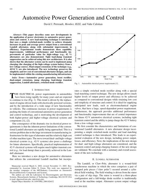
Fig. 1. Automobile electrical power requirements [1].<br />
I. INTRODUCTION<br />
THE ELECTRICAL power requirements in automobiles<br />
have been rising rapidly for many years <strong>and</strong> are expected<br />
to continue to rise (Fig. 1). This trend is driven by the replacement<br />
of engine-driven loads with electrically-powered versions,<br />
<strong>and</strong> by the introduction of a wide range of new functionality<br />
in vehicles. The continuous increase in power requirements is<br />
pushing the limits of conventional automotive power generation<br />
<strong>and</strong> control technology, <strong>and</strong> is motivating the development of<br />
both higher-power <strong>and</strong> higher-voltage electrical systems <strong>and</strong><br />
components [1], [2].<br />
One consequence of the dramatic rise in electrical power requirements<br />
is that the inherent power limitations of the conventional<br />
Lundell alternator are rapidly being approached. This is a<br />
serious problem due to the large investment in manufacturing infrastructure<br />
for this type of alternator <strong>and</strong> the relatively high cost<br />
of other machine types. The move toward dual- <strong>and</strong> high-voltage<br />
electrical systems (e.g., 42-V systems) also poses a challenge<br />
for future alternators. Specifically, practical implementation of<br />
42-V electrical systems will require much tighter transient control<br />
(e.g., for load dump) than is presently achieved in the Lundell<br />
alternator.<br />
Here we introduce a new design for automotive alternators<br />
that utilizes the conventional Lundell machine but incorpo-<br />
Manuscript received March 6, 2002; revised November 13, 2003. Recommended<br />
by Associate Editor N. Femia. This work was supported by<br />
the member companies of the MIT/Industry Consortium on <strong>Automotive</strong><br />
Electrical/Electronic Components <strong>and</strong> Systems.<br />
The authors are with the Laboratory for Electromagnetic <strong>and</strong> Electronic<br />
Systems, Massachusetts Institute of Technology, Cambridge, MA 02139 USA<br />
(e-mail: djperrea@mit.edu; vahe@mit.edu).<br />
Digital Object Identifier 10.1109/TPEL.2004.826432<br />
rates a simple switched mode rectifier along with a special<br />
load-matching control technique. The new design allows much<br />
higher levels of output power <strong>and</strong> efficiency to be achieved<br />
as compared to conventional designs while retaining low cost<br />
<strong>and</strong> simplicity of structure <strong>and</strong> control. It is ideal for supplying<br />
anticipated new loads, such as electromechanical engine<br />
valves, that have a large, speed-dependent power requirement.<br />
Furthermore, the approach provides additional performance<br />
<strong>and</strong> functionality improvements that are of central importance<br />
for future 42-V automotive electrical systems, including tight<br />
transient control <strong>and</strong> the ability to jump charge the 42-V battery<br />
from a low-voltage source.<br />
We first consider the characteristics <strong>and</strong> limitations of conventional<br />
Lundell alternators. A new alternator design incorporating<br />
a simple switched-mode rectifier <strong>and</strong> load matching<br />
control technique is then introduced. This leads to an experimental<br />
evaluation of the new design, including power output,<br />
losses, <strong>and</strong> efficiency. Next, the implications of the new design<br />
for dual- <strong>and</strong> high-voltage alternators are considered, <strong>and</strong> the<br />
transient control <strong>and</strong> jump-charging features of the new design<br />
are validated. We conclude with a summary <strong>and</strong> overall assessment<br />
of the new technology.<br />
II. LUNDELL ALTERNATOR<br />
The Lundell, or Claw–Pole, alternator is a wound-field<br />
synchronous machine in which the rotor comprises a pair of<br />
stamped pole pieces (“claw poles”) secured around a cylindrical<br />
field winding. The field winding is driven from the stator<br />
via a pair of slip rings. The stator is wound in a three-phase<br />
configuration <strong>and</strong> a full-bridge diode rectifier is traditionally<br />
used at the machine output. Alternator system output voltage<br />
0885-8993/04$20.00 © 2004 <strong>IEEE</strong>
PERREAULT AND CALISKAN: AUTOMOTIVE POWER GENERATION AND CONTROL 619<br />
(or current) is controlled by regulating the field current. A relatively<br />
long field time constant <strong>and</strong> a high armature synchronous<br />
reactance are characteristic of this type of alternator, <strong>and</strong> tend<br />
to dominate its electrical performance.<br />
A. Simple Alternator Electrical Model<br />
Fig. 2 shows a simple electrical model for a Lundell alternator<br />
system. The field current of the machine is determined<br />
by the field current regulator which applies a pulse-width modulated<br />
voltage across the field winding. Average field current<br />
is determined by the field winding resistance <strong>and</strong> the average<br />
voltage applied by the regulator. Changes in field current occur<br />
with an / field-winding time constant that is typically on the<br />
order of 100 ms or more.<br />
The armature is modeled as a Y-connected set of sinusoidal<br />
three-phase back emf voltages , <strong>and</strong> <strong>and</strong><br />
synchronous inductances . The electrical frequency of the<br />
back emf voltages is proportional to the alternator mechanical<br />
speed <strong>and</strong> the number of machine poles .<br />
The magnitude of the back emf voltages is proportional to both<br />
frequency <strong>and</strong> field current<br />
(1)<br />
A diode bridge rectifies the ac machine outputs into a constant<br />
voltage representing the battery <strong>and</strong> associated loads. As will<br />
be seen, this simple model captures many of the important characteristics<br />
of alternators while remaining analytically tractable.<br />
Other effects, such as stator resistance <strong>and</strong> mutual coupling,<br />
magnetic saturation, waveform harmonic content, etc., can also<br />
be incorporated into the model at the expense of simplicity.<br />
B. Alternator Electrical Behavior<br />
To characterize alternator electrical behavior we turn to the<br />
simple electrical model of Fig. 2. The constant-voltage load of<br />
the rectifier makes the analysis of the system different from the<br />
classic case of a rectifier system with a current-source (or inductive)<br />
load. Nevertheless, with reasonable approximations the behavior<br />
of this system can be described analytically [3], [4]. For<br />
example, alternator output power versus operating point can be<br />
calculated as<br />
where is the output voltage, is the back emf magnitude,<br />
is the electrical frequency, <strong>and</strong> is the armature synchronous<br />
inductance.<br />
Fig. 3 shows the calculated output power versus output<br />
voltage of a conventional 14-V automotive alternator at constant<br />
(full) field current, parameterized by the speed of the<br />
alternator. As can be seen, for any given speed there is a substantial<br />
variation in output power capability with output voltage.<br />
At each speed there is an output voltage above which the output<br />
current (<strong>and</strong> hence output power) becomes zero. This voltage<br />
corresponds to the peak of the line-to-line back emf voltage,<br />
above which the diodes in Fig. 2 will not conduct. At each speed<br />
there is also a single output voltage at which maximum output<br />
power is achieved, <strong>and</strong> this output voltage is substantially below<br />
the line-to-line back emf voltage magnitude. This behavior can<br />
(2)<br />
Fig. 2.<br />
Simple Lundell alternator model.<br />
be traced to the large armature synchronous inductances of<br />
the Lundell machine. Significant voltage drops occur across<br />
the synchronous inductances when current is drawn from the<br />
machine, <strong>and</strong> these drops increase with increasing output current<br />
<strong>and</strong> operating speed. Consequently, the Lundell alternator<br />
exhibits heavy load regulation when used with a diode rectifier.<br />
For example, in a typical automotive alternator, back voltages<br />
in excess of 80 V may be needed to source rated current into a<br />
14-V output at high speed. An appropriate dc-side model for<br />
the system is a large open circuit voltage in series with a large<br />
speed- <strong>and</strong> current-dependent output impedance. The output<br />
power versus output voltage characteristics of Fig. 3 may<br />
then be understood in terms of the maximum power transfer<br />
theorem for a source with output impedance. In short, the high<br />
armature synchronous reactance of the Lundell machine results<br />
in a large dc-side output impedance, <strong>and</strong> necessitates the use<br />
of large back-emf voltages to source rated current. This high<br />
alternator output impedance results in the power deliverable by<br />
the alternator at a given speed to be maximized only at a single<br />
“load matched” output voltage.<br />
Consider the operational characteristics of the automotive alternator<br />
system described by Fig. 3. The output power versus<br />
output voltage curves of Fig. 3 are calculated for constant (full)<br />
field current <strong>and</strong> parameterized by the speed of the alternator,<br />
with 1800 rpm corresponding to idle speed <strong>and</strong> 6000 rpm corresponding<br />
to cruising speed. At any given speed <strong>and</strong> output<br />
voltage, output power can be reduced below the value shown by<br />
reducing the field current, which in turn reduces the back-emf<br />
voltage <strong>and</strong> output current. If the alternator is used at the designed<br />
output voltage of 14 V, then the output power capability<br />
across speed is represented by the vertical 14-V locus intersecting<br />
the curves of Fig. 3. The alternator delivers its maximum<br />
idle speed power near the 14-V design voltage. At higher speeds<br />
<strong>and</strong> 14-V output, the alternator delivers more power (up to about<br />
1500 W at 6000 rpm), but does not achieve the maximum power<br />
possible across voltage because of the way the voltage-power<br />
curve changes with engine speed. At 42-V output <strong>and</strong> 6000 rpm,<br />
for example, the alternator can deliver over 3500 W. Nevertheless,<br />
this alternator could not usually be used for a 42-V system,<br />
because at 42-V output <strong>and</strong> lower speeds the output power drops
620 <strong>IEEE</strong> TRANSACTIONS ON POWER ELECTRONICS, VOL. 19, NO. 3, MAY 2004<br />
Fig. 3.<br />
Alternator operating loci for 14-V <strong>and</strong> 42-V operation.<br />
off rapidly, with no power generation at idle speed. Thus, the<br />
need to generate sufficient power at the low speed means that<br />
the peak power capability of the machine across voltage is not<br />
achieved at higher speeds.<br />
As described above, the output power versus output voltage<br />
curves of Fig. 3 are well-suited to an output voltage of 14 V,<br />
but not suitable for use at a higher voltage such as 42 V. If one<br />
wanted to operate at 42 V, one could rewind the stator with three<br />
times as many turns of wire having about the cross-sectional<br />
area. This would have the effect of stretching the horizontal<br />
axis in Fig. 3 such that the all the curves would peak with<br />
the same output power at 3 times the output voltage (e.g., with<br />
the 1800-rpm curve peaking near 42 V) 1 . Thus, to first order,<br />
the output power capability of an alternator of a given size does<br />
not depend on the output voltage for which it is designed, since<br />
the stator may be rewound to provide the same power characteristics<br />
versus speed at any other fixed output voltage.<br />
III. LOAD MATCHING CONCEPT<br />
We now introduce a new design <strong>and</strong> control approach for automotive<br />
alternators. The new alternator system utilizes both<br />
field control <strong>and</strong> a simple switched-mode rectifier to achieve<br />
substantially higher levels of power <strong>and</strong> performance than are<br />
obtained conventionally. High power is achieved by utilizing the<br />
switched-mode rectifier as a second control h<strong>and</strong>le to properly<br />
match the constant-voltage load to the alternator.<br />
A. SMR Load Matching<br />
Consider the alternator <strong>and</strong> switched-mode rectifier shown in<br />
Fig. 4. In this system, a diode bridge is followed by a “boost<br />
switch set” comprising a controlled switch (such as a MOSFET)<br />
<strong>and</strong> a diode . The switch is turned on <strong>and</strong> off at high<br />
frequency in a pulse-width modulation (PWM) fashion with<br />
duty ratio . The diode bridge operates in continuous conduction<br />
1 This may be seen by examining (1) <strong>and</strong> (2). Tripling the number of turns<br />
would raise the synchronous inductance by approximately a factor of nine <strong>and</strong><br />
raise the back emf voltage by a factor of three. Since the output voltage is tripled<br />
the output power capability will remain unchanged.<br />
Fig. 4. Switched-mode rectifier: (a) matching stage inserted in an alternator<br />
<strong>and</strong> (b) representative waveforms.<br />
mode (CCM), so that the diode is on when is off. The<br />
PWM operation of <strong>and</strong> causes the voltage to be a pulsating<br />
waveform with an average value dependent on the output<br />
voltage <strong>and</strong> the duty ratio . Neglecting device drops, <strong>and</strong><br />
assuming is relatively constant over a PWM cycle, we may<br />
calculate the local average value of as<br />
Similarly, assuming the diode bridge output current is approximately<br />
constant over a switching cycle, we may calculate<br />
the local average output current, , of the alternator system as<br />
In an averaged sense, the boost switch set acts a dc transformer<br />
with a turns ratio controlled by the PWM duty ratio . Because<br />
the PWM frequency is much higher than the ac frequency <strong>and</strong><br />
the machine inductances are relatively large, the alternator<br />
machine <strong>and</strong> diode bridge react to the average value of almost<br />
exactly as they would to the output voltage in a conventional<br />
diode-rectified alternator. As a result, by controlling the<br />
duty ratio , one has control over the average voltage at the<br />
output of the bridge, , to any value below the true output<br />
voltage of the alternator system, . The switched-mode rectifier<br />
(SMR) can thus be used as an additional control h<strong>and</strong>le<br />
to extract much higher levels of performance from the alternator.<br />
For example, consider that in the present system, the maximum<br />
possible output power of the alternator at a given speed<br />
<strong>and</strong> field current is determined by the average of , not by<br />
the output voltage . By adjusting the duty ratio , the alternator<br />
can generate up to its maximum power (across voltage)<br />
as speed varies, while supplying a constant output voltage, ,<br />
(of 50 V, for example). As illustrated in Fig. 5, this operating<br />
mode allows much more power to be drawn from the machine<br />
(3)<br />
(4)
PERREAULT AND CALISKAN: AUTOMOTIVE POWER GENERATION AND CONTROL 621<br />
Fig. 5. Alternator operating locus for load-matched operation. The alternator<br />
operates at the peak of the alternator power/voltage curve at every speed.<br />
at most speeds than is achievable with a diode rectifier supplying<br />
a fixed output voltage (Fig. 3). What makes this possible is that<br />
the switched-mode rectifier provides the necessary controlled<br />
voltage transformation to match the constant-voltage load to the<br />
alternator. This load matching is most simply achieved by appropriately<br />
controlling the SMR duty ratio as a function of alternator<br />
speed. The output power can be efficiently regulated to<br />
any value below the achievable maximum with field control.<br />
Examining the output power versus output voltage curves of<br />
Figs. 3 <strong>and</strong> 5, we see that while this particular machine is suited<br />
for use at 14-V output with a diode rectifier, with the new SMR<br />
load-matching technique <strong>and</strong> the boost-type rectifier of Fig. 4, it<br />
is better suited to a higher output voltage (e.g., 50–55 V). Fig. 6<br />
shows the output power capability (at full field) for this (theoretical)<br />
machine characteristic as a function of alternator speed<br />
for different operating conditions. Utilized with a diode rectifier<br />
at its optimized voltage of 14 V, the machine is capable of<br />
generating approximately 1 kW at idle (1800 rpm), increasing<br />
up to approximately 1.5 kW at cruising speed (6000 rpm). Operating<br />
with the new SMR load-matching technique at its (approximately<br />
optimal) voltage of 50-V output, the machine is capable<br />
of similar performance at idle, but its power capability<br />
increases to 4 kW at cruising speed! This tremendous improvement<br />
in power capability is not fundamentally due to the change<br />
in output voltage, since to first order the machine can be rewound<br />
to operate at any voltage with the same power capability.<br />
Rather, the improvement results from utilizing an additional<br />
degree of control freedom to achieve load matching across<br />
the speed range.<br />
It should also be pointed out that a machine suitable for diode<br />
rectification at 14 V may also be directly employed at 42 V<br />
(without rewinding) by utilizing a switched-mode rectifier <strong>and</strong><br />
the new load-matching technique. This is relevant due to the<br />
imminent introduction of 42-V automotive electrical systems<br />
which will require 42-V alternators. Operation under this condition<br />
is also illustrated in Fig. 6. For much of the speed range,<br />
load matching can be achieved at full field, <strong>and</strong> the maximum<br />
Fig. 6. Analytical prediction of alternator output power versus speed at full<br />
field current for different operating conditions.<br />
load-matched power can be achieved. Above a certain speed, the<br />
SMR duty ratio goes to zero <strong>and</strong> load matching can no longer<br />
be maintained. The machine again sees the actual (fixed) output<br />
voltage, which results in high-power operation but not as high<br />
as could be achieved under load-matched conditions. With the<br />
new approach, even present 14-V alternator designs are suitable<br />
for high-power operation at 42-V output; only the rectifier stage<br />
<strong>and</strong> controls need to be changed, <strong>and</strong> one could even conceive<br />
of manufacturing both 42-V <strong>and</strong> 14-V machines on the same<br />
production line. Thus, the load-matching approach is timely for<br />
meeting the dem<strong>and</strong>s of higher power <strong>and</strong> higher voltage alternators<br />
in the automotive industry.<br />
B. Average <strong>Power</strong> Improvement<br />
With the new SMR load-matching technique, substantial increases<br />
in alternator output power can be achieved, particularly<br />
at speeds above idle. The curves of Fig. 6 indicate that, using<br />
the load-matching technique, the alternator power capability increases<br />
almost linearly with speed between idle <strong>and</strong> cruising<br />
speed. This contrasts with the case of a conventional diode-rectified<br />
alternator in which the available output power is relatively<br />
flat over much of the speed range. For some automotive loads<br />
the improved power capability with speed is ideal. For example,<br />
the power requirement of electromechanical engine valves (a future<br />
automotive electrical load) increases almost linearly with<br />
speed, from a small value at idle to a large value (as much<br />
as 2 kW) at cruising speed. Other types of high-power loads<br />
(e.g., heated windscreens) do not have a speed-dependent power<br />
requirement, <strong>and</strong> thus do not fully benefit from the increased<br />
power output capability at higher speeds.<br />
To better characterize the average power improvement provided<br />
by the load-matching technique, we have examined the<br />
alternator power output over an FTP72 drive cycle. This drive<br />
cycle, illustrated in Fig. 7, contains idling time, city driving,<br />
<strong>and</strong> a small amount of highway-speed driving. Based on the<br />
maximum power versus speed characteristics of Fig. 6, it was<br />
found that the average power capability of a properly wound
622 <strong>IEEE</strong> TRANSACTIONS ON POWER ELECTRONICS, VOL. 19, NO. 3, MAY 2004<br />
Fig. 7. FTP72 drive cycle: alternator shaft speed (top) <strong>and</strong> road speed<br />
(bottom).<br />
TABLE I<br />
AVAILABLE OUTPUT POWER OVER THE FTP72 DRIVE<br />
CYCLE FOR DIFFERENT RECTIFIER SYSTEMS<br />
load-matched machine is approximately a factor of 1.9 higher<br />
than that of a conventional diode-rectified machine of the same<br />
size. Also, utilizing a conventional 14-V machine (not rewound)<br />
with SMR load matching at 42 V also provides an average power<br />
capability improvement of about 1.9. These results, summarized<br />
in Table I, indicate that a given size machine is capable of almost<br />
twice the average power output capability over a drive cycle<br />
when the new SMR load-matching technique is employed! It<br />
also means that the alternator size required to achieve a given<br />
output power requirement is roughly halved using the new technique;<br />
this represents a substantial savings in alternator size,<br />
mass, <strong>and</strong> cost.<br />
C. Other SMR Structures<br />
The switched-mode rectifier of Fig. 4 has been used in both<br />
continuous <strong>and</strong> discontinuous conduction modes in other contexts<br />
(see [5]–[7] for example). As applied here, this simple<br />
boost-type rectifier allows the output power capability of the alternator<br />
system to be increased by properly matching the fixed<br />
output voltage to that required by the alternator for maximum<br />
output power.<br />
Many other simple switched-mode rectifiers can also be<br />
utilized to achieve the desired load-matching effect (Fig. 8).<br />
Note that while all of these rectifier topologies have been<br />
proposed previously (e.g., [7]), they have not been employed<br />
in the manner described here.<br />
One boost-type switched-mode rectifier that is of particular<br />
advantage in automotive applications is shown in Fig. 8(e). In<br />
this switched-mode rectifier, the boost stage has been incorporated<br />
into the bridge, saving a device drop as compared to<br />
the circuit of Fig. 4. The operation of the rectifier in Fig. 8(e)<br />
is very similar to the operation of a st<strong>and</strong>ard three-phase rectifier.<br />
When a particular phase (for example, phase a) is carrying<br />
a positive current, the MOSFET <strong>and</strong> the diode of that leg<br />
form a boost switch set <strong>and</strong> are utilized in a similar manner to<br />
the MOSFET/diode combination in Fig. 4. The remaining legs<br />
(phases b <strong>and</strong> c in our example) carry the negative (return) current<br />
back to the machine. To simplify the control strategy, all<br />
three ground referenced switches , <strong>and</strong> are gated on<br />
<strong>and</strong> off together with duty ratio . With a slight degree of additional<br />
control, the active devices can also be used to provide synchronous<br />
rectification, further reducing conduction losses. This<br />
topology is particularly simple <strong>and</strong> inexpensive to implement<br />
<strong>and</strong> only represents a slight structural change from the diode rectifier<br />
in use today. While fundamental design <strong>and</strong> control techniques<br />
we describe here work with a wide range of SMR topologies,<br />
for simplicity we will focus on the topology of Fig. 8(e) for<br />
the remainder of the paper.<br />
D. Alternator <strong>Control</strong><br />
The static control goal for the alternator system is to regulate<br />
the output voltage for load requirements from zero up to<br />
the maximum achievable power. In the proposed approach this<br />
is accomplished by properly selecting the alternator field current<br />
(or field regulator duty ratio) <strong>and</strong> SMR duty ratio as a<br />
function of output voltage <strong>and</strong> alternator speed. A unique control<br />
comm<strong>and</strong> exists which will produce maximum power at<br />
a given speed (i.e., full field current at the proper SMR duty<br />
ratio for load matching). For many operating points (when less<br />
than full power is required) there are multiple control combinations<br />
which will yield the desired output voltage. As a result,<br />
there is some freedom to achieve objectives in addition to increased<br />
output power capability (e.g., maximizing efficiency)<br />
in selecting a control law. The SMR duty ratio control law for<br />
achieving load matching with a boost converter is<br />
where is the field current, is the alternator angular speed,<br />
is the machine back-emf constant, <strong>and</strong> is the output voltage.<br />
To achieve load matching, one thus controls the complement of<br />
the SMR duty ratio to be proportional to the field current <strong>and</strong><br />
the alternator speed. In general, the alternator angular speed is<br />
available (from the tachometer) while the field current is easily<br />
measurable at the field regulator if desired. (Note that unlike<br />
other machine control techniques, such as field-oriented control,<br />
there is no need for position or stator current information <strong>and</strong><br />
the control law can be implemented with simple, inexpensive<br />
circuitry.)<br />
The simplest control approach is to use conventional field<br />
control to regulate the output voltage <strong>and</strong> select the SMR duty<br />
ratio as<br />
where is the full field current <strong>and</strong> is a net proportionality<br />
constant between duty ratio complement <strong>and</strong> angular<br />
speed. With this simple control law, the output voltage can be<br />
controlled from zero power up to the maximum load-matched<br />
power across speed.<br />
A more sophisticated control approach is to again use field<br />
control to regulate the output voltage, but to set the SMR duty<br />
ratio (or its complement) using the actual instantaneous field<br />
current (which can be easily measured at the field regulator) as<br />
(5)<br />
(6)
PERREAULT AND CALISKAN: AUTOMOTIVE POWER GENERATION AND CONTROL 623<br />
Fig. 8.<br />
Various switched-mode rectifier implementations: (a) push-pull, (b) SEPIC <strong>and</strong> (c) Cuk, (d) isolated Cuk, <strong>and</strong> (e) boost semi-bridge.<br />
per (5). In addition to allowing the output voltage to be properly<br />
regulated over the full power range, this control law also ensures<br />
that load matching is achieved at all operating points.<br />
In conventional automotive alternators, the conduction losses<br />
in the stator windings <strong>and</strong> the semiconductor devices represent<br />
a dominant portion of the alternator losses. In this case, if one<br />
wants to maximize the alternator efficiency over all load conditions,<br />
one should choose the alternator control law such that<br />
the alternator system always generates the needed output power<br />
utilizing the lowest stator <strong>and</strong> device currents possible. This is<br />
done by controlling the SMR so that the alternator always sees<br />
the largest effective voltage that can be used for that level<br />
of output power. For a boost-type SMR, this is done by ensuring<br />
that the lowest duty ratio possible (for the required level<br />
of output power) is always used. One simple controller structure<br />
which achieves this is illustrated in Fig. 9.<br />
In Fig. 9, the conventional control mechanism is formed by<br />
the compensator (usually a lag controller) <strong>and</strong> the field current<br />
regulator. Given an output power dem<strong>and</strong>, the average value<br />
of the field current is adjusted to maintain the average value of<br />
the output voltage equal to the reference voltage . If the<br />
required power level is low enough, field current regulation is<br />
sufficient in delivering power to the load. In this mode of operation<br />
the compensator output <strong>and</strong> the limiter output are<br />
both less than one. As a result, the input to the controlled limiter<br />
<strong>and</strong> therefore the duty ratio of the MOSFETs is 0.<br />
With field current regulation at a zero duty ratio, the controller<br />
operates in the same manner as today’s automotive regulator.<br />
If the power dem<strong>and</strong> is further increased at a given alternator<br />
speed, field current alone will no longer be sufficient to support<br />
the output power. At this point, the compensator output will<br />
increase beyond 1 which will force the field current regulator to<br />
supply maximum current. With the field current at its maximum<br />
<strong>and</strong> the compensator output increasing beyond 1, the input to<br />
the controlled limiter will increase from 0. The increase of<br />
signal from zero will result in an appropriate control signal<br />
to generate a duty ratio for the MOSFETs to provide the dem<strong>and</strong>ed<br />
output power. The duty ratio will be increased by an
624 <strong>IEEE</strong> TRANSACTIONS ON POWER ELECTRONICS, VOL. 19, NO. 3, MAY 2004<br />
Fig. 9.<br />
Alternator with switched-mode rectifier <strong>and</strong> efficiency optimizing controller.<br />
amount necessary to support the output power or to reach the<br />
load-matched condition, whichever is lower. The duty ratio corresponding<br />
to the load-matched condition is set by on the<br />
controlled limiter <strong>and</strong> is derived from a speed sensor using the<br />
function (6). The fault protection controller can be implemented<br />
in a variety of ways to provide immunity from system<br />
transients. In its simplest form, it can be a crowbar <strong>and</strong> reset<br />
trigger on the devices. For example, in the event of a load-dump<br />
transient, the MOSFETs can be turned on <strong>and</strong> field field current<br />
turned off to force the phase currents to decay to zero.<br />
A variety of other control laws also exist. In general, the field<br />
current (or field regulator duty ratio) <strong>and</strong> SMR duty ratio are<br />
jointly selected as a function of output voltage <strong>and</strong> speed to regulate<br />
the output voltage, achieve high-power operation (when<br />
needed), <strong>and</strong> achieve other goals at partial load (such as maximizing<br />
efficiency). What all such controllers share is the regulation<br />
of the SMR for the load-matched condition when maximum<br />
output power is needed.<br />
IV. EXPERIMENTAL DEMONSTRATION OF LOAD MATCHING<br />
In this section, we provide experimental results of the load<br />
matching technique that support the analytical results presented<br />
in the earlier sections.<br />
A. Description of Experimental Setup<br />
The experimental setup consists of a st<strong>and</strong>ard Lundell automotive<br />
alternator (Ford 130 A) driven by a computer-controlled<br />
variable speed drive. Also included in the test st<strong>and</strong> is a dynamometer<br />
which is utilized to measure the mechanical power<br />
into the alternator. For the purposes of our experiments, the internal<br />
alternator field current regulator is disabled <strong>and</strong> a constant<br />
field current is supplied to the alternator by using an external<br />
power supply (<br />
A). The full-bridge three-phase rectifier<br />
that is a part of the original alternator assembly is disabled<br />
in order to connect the phases directly to the SMR. The alternator<br />
is loaded by the parallel combination of an electronic load<br />
(HP6050A) <strong>and</strong> a resistor bank. The electronic load is also utilized<br />
to set the output voltage level.<br />
The switched-mode rectifier used in the prototype system<br />
is of the topology illustrated in Fig. 8(e). The diodes are each<br />
implemented with an IXYS DSS2X41-01A Schottky diode<br />
module (comprising 2 paralleled diodes each nominally rated at<br />
40 A <strong>and</strong> 100 V). The active switches are IXYS IXFN230N10<br />
power MOSFETs (6 m nominal, 100 V). Tightly coupled<br />
across the output of the switched-mode rectifier (output<br />
to ground) are six paralleled ITW Paktron 106K100CS4<br />
multilayer polymer film capacitors (10 F, 100 V). These<br />
capacitors serve to suppress the high-frequency switching<br />
currents developed at the output of the boost rectifier. The
PERREAULT AND CALISKAN: AUTOMOTIVE POWER GENERATION AND CONTROL 625<br />
Fig. 10. Alternator output power versus alternator output voltage for several<br />
speeds. Solid <strong>and</strong> dashed plots correspond to analytical <strong>and</strong> experimental results,<br />
respectively.<br />
Fig. 11. Alternator output power versus speed for different operating<br />
conditions: comparison of analytical <strong>and</strong> experimental results.<br />
power MOSFETs are each driven through a resistor/diode<br />
network by a UC2710 gate driver. The devices are modulated<br />
together with a specified duty ratio at a switching frequency of<br />
100 kHz using a UC3823A pulse-width modulation IC. <strong>Power</strong><br />
<strong>and</strong> control interconnects are implemented on a printed circuit<br />
board, with the power devices also attached to a heat sink (IMI<br />
Marston 96CN02500A200, 0.29 C/W with free convection).<br />
This design was found to be robust <strong>and</strong> suitable for bench-top<br />
validation of the proposed approach.<br />
B. Experimental Results Versus Speed<br />
To verify the analytical results presented Section II, a number<br />
of tests were performed at several alternator speeds. At a given<br />
constant speed, the alternator system output voltage, ,was<br />
varied <strong>and</strong> the resulting output power recorded in order to validate<br />
the analytical results shown in Fig. 3. The results of these<br />
tests are summarized in Fig. 10 where the dashed curves represent<br />
the experimental results <strong>and</strong> the solid lines are the analytical<br />
results from Fig. 3. As can be seen from this figure, there is<br />
good agreement between the measurements <strong>and</strong> the analytical<br />
results. The agreement between the experimental <strong>and</strong> analytical<br />
results show the validity of our simplified analytical models despite<br />
the approximations that were utilized in their derivation.<br />
To validate the analytical results of Fig. 6, the alternator <strong>and</strong><br />
switched-mode rectifier were utilized across a range of speeds<br />
<strong>and</strong> output voltages with both diode rectification <strong>and</strong><br />
under the load-matched condition of (5). The dashed curves in<br />
Fig. 11 shows the measured maximum power output of the alternator<br />
system for three cases: diode rectification at 14 V <strong>and</strong><br />
switched-mode rectification at 42 V <strong>and</strong> 50 V. The solid lines in<br />
the figure are identical to the curves of Fig. 6 <strong>and</strong> are repeated<br />
for the sake of comparison. Once again, the experimental results<br />
validate the analytical results derived earlier in the report.<br />
Clearly, tremendous increases in output power are achievable<br />
across speed using the new SMR load-matching technique.<br />
Fig. 12. Experimentally-determined alternator losses at full field across speed<br />
for different operating modes. The SMR load-matching technique (at its optimal<br />
output voltage) yields the same or lower losses than diode rectification at its<br />
optimal output voltage.<br />
C. <strong>Power</strong> Losses<br />
As described in earlier in this section, the experimental test<br />
st<strong>and</strong> includes a dynamometer which allowed the measurement<br />
of mechanical input power to the alternator system. Using the<br />
measurements of electrical output power <strong>and</strong> mechanical input<br />
power, one can plot the power loss in the alternator system.<br />
Shown in Fig. 12 are the measured power losses versus speed<br />
at full field for the alternator system utilizing a diode rectifier<br />
at 14 V <strong>and</strong> a switched-mode rectifier at 50 V. (Again, these<br />
voltages represent the optimal output voltages of the two operating<br />
modes for the alternator used in the experiments. Similar<br />
results are obtainable in each mode at other output voltages<br />
merely by rewinding the machine stator appropriately.) This<br />
figure shows that the power losses associated with the alternator<br />
system using switched-mode rectifier load-matching are<br />
less than or equal to the ones with diode rectification over the
626 <strong>IEEE</strong> TRANSACTIONS ON POWER ELECTRONICS, VOL. 19, NO. 3, MAY 2004<br />
Fig. 13. Experimentally-determined alternator efficiency at full field across<br />
speed for different operating modes.<br />
range of operating speeds. This results primarily from the fact<br />
that the new operating technique utilizes the same (or lower)<br />
stator <strong>and</strong> device currents than the conventional diode rectifier<br />
approach at all operating speeds. Thus, we can conclude that the<br />
proposed load-matched operating technique is actually advantageous<br />
from a thermal design point of view.<br />
D. Efficiency Improvement<br />
Since the proposed system achieves both lower losses <strong>and</strong> increased<br />
power output, the efficiency of the overall system is improved<br />
tremendously. The experimentally-measured mechanical<br />
input to electrical output efficiency at full-field is plotted in<br />
Fig. 13 for the alternator system using conventional diode rectification<br />
at 14 V <strong>and</strong> SMR load-matching at 50 V. With the conventional<br />
diode rectified system, the efficiency starts at around<br />
61% at idle speed of around 1800 rpm <strong>and</strong> declines to about 45%<br />
near the cruising speed of 6000 rpm. With the switched-mode<br />
rectified system, the efficiency also starts near 61% at idle speed<br />
but increases to about 71% at cruising speed. This represents<br />
a dramatic improvement in the efficiency of the alternator. The<br />
improved efficiency provided by the new SMR load-matching is<br />
valuable from a fuel economy <strong>and</strong> environmental point of view<br />
<strong>and</strong> will become even more so as the average electrical loads in<br />
vehicles continue to increase.<br />
V. LOAD DUMP PROTECTION<br />
As discussed in earlier sections, the Lundell alternator has<br />
large stator synchronous reactances which in turn have large<br />
reactive voltage drops during normal operation. As a result,<br />
very large machine back-emf voltage magnitudes are needed to<br />
source the rated machine current. If a large current consuming<br />
load is suddenly removed from the alternator output terminals,<br />
the reactive drops become smaller <strong>and</strong> a larger fraction of the<br />
back-emf voltage appears at the alternator output while the field<br />
current is reduced by the regulator. The resulting transient is<br />
commonly referred to as a load dump transient. In today’s14V<br />
alternators, the load dump transient can have peak voltages of<br />
Fig. 14. Experimental demonstration of load dump transient suppression<br />
using the switched-mode rectifier (horizontal: 500 s/div; vertical: 10 A/div,<br />
10 V/div).<br />
80 V <strong>and</strong> last hundreds of milliseconds. In 42-V machines, the<br />
transient peak may reach hundreds of volts. This is unlikely to<br />
be acceptable in practice, motivating the search for effective,<br />
inexpensive transient suppression techniques. In this section, it<br />
is shown that load dump transient suppression can be achieved<br />
through proper utilization of the switched-mode rectifier.<br />
A. Use of SMR for Load Dump Protection<br />
Load dump transient fault protection can easily be implemented<br />
within the framework of the new system. A fault protection<br />
controller is utilized to detect <strong>and</strong> manage load dump<br />
transients in the system through appropriate control of the field<br />
current <strong>and</strong> SMR duty ratio. When a significant overvoltage is<br />
detected at the output terminals of the alternator system, the fault<br />
protection controller acts to decrease the field current <strong>and</strong> adjust<br />
the SMR duty ratio to limit the load dump transient at the alternator<br />
output.<br />
In the simplest version of the approach, the boost switch(es)<br />
of the SMR can be turned on continuously (crowbar operation)<br />
<strong>and</strong> the field current regulator can be adjusted for deexcitation<br />
of the field until the field current <strong>and</strong> machine currents are at an<br />
acceptable level. A more sophisticated version of the approach<br />
would adjust the pulse-width modulation of the switched-mode<br />
rectifier in concert with the field current regulator to regulate the<br />
output voltage <strong>and</strong> suppress the transient.<br />
B. Experimental Results<br />
Fig. 14 shows the experimental results of a load dump transient<br />
test on an SMR-based system with an output voltage of<br />
50 V. The output current of the system is suddenly reduced from<br />
50 A to 30 A (2.5 kW to 1.5 kW), thus inducing a load dump<br />
transient. Using active transient suppression control via the<br />
switched-mode rectifier, a transient having a peak overvoltage<br />
of 25 V <strong>and</strong> lasting about 100 s occurs. In a conventional<br />
diode rectified system the overvoltage would exceed 100 V<br />
<strong>and</strong> last hundreds of milliseconds. It should be noted that the<br />
short, low-energy transient in the new system can be further
PERREAULT AND CALISKAN: AUTOMOTIVE POWER GENERATION AND CONTROL 627<br />
clamped using a transient voltage suppressor (TVS). This is<br />
much less practical with the long, high-voltage transients in<br />
conventional systems. It may be concluded that rapid transient<br />
suppression can be achieved within the framework of the new<br />
system. This is valuable in present-day 14-V alternators, <strong>and</strong> of<br />
central importance for future high-voltage alternator systems.<br />
VI. JUMP START TECHNIQUE<br />
There is a desire to introduce 42 V <strong>and</strong> dual -V automotive<br />
electrical systems in the near future. Providing jump<br />
start capability for 42-V systems from 14 V or 28 V is a major<br />
deployment issue. To solve the jump-start problem, expensive<br />
dc/dc converter solutions are usually considered. In this section,<br />
we show that jump start can be implemented using the alternator<br />
<strong>and</strong> the switched mode rectifier. It is shown that the low<br />
voltage charging source connected between the machine neutral<br />
<strong>and</strong> system ground can be used to charge the 42-V bus by<br />
utilizing the alternator synchronous inductances <strong>and</strong> SMR as a<br />
dc/dc converter.<br />
Fig. 15.<br />
42-V jump start charging technique using the SMR.<br />
A. Motivation<br />
A dual- or high-voltage system having a starter motor coupled<br />
to a high-voltage bus requires a charged high-voltage battery<br />
to start. In cases where the high-voltage battery is not fully<br />
charged or is depleted, it is desirable to be able to charge the depleted<br />
high- voltage battery from a low-voltage source (such as<br />
a 14-V or 28-V system) in order to provide jump-start capability<br />
for dual/high voltage systems. In an automobile which includes<br />
only a single high-voltage system, one may desire to transfer energy<br />
from a low-voltage power source, battery or alternator of<br />
a different vehicle to the high-voltage system. In a dual-voltage<br />
system, one may desire to transfer energy from the low-voltage<br />
battery of the dual-voltage system to the high voltage battery of<br />
the dual-voltage system or from the low-voltage battery or alternator<br />
of a different vehicle to the high voltage battery of the<br />
dual-voltage system.<br />
B. Jump-Charging Implementation<br />
Here we show that the alternator <strong>and</strong> switched-mode rectifier<br />
can be used to implement jump charging in dual/high voltage<br />
systems (e.g., 42-V or -V systems.) One possible way to<br />
implement jump-charging within the framework of the new alternator<br />
system is shown in Fig. 15. In this scheme, the positive<br />
terminal of the charging source is connected to the machine<br />
neutral while the negative terminal of the charging source<br />
is connected to system ground. (Note that the machine back-emf<br />
voltage sources are not present since the engine/alternator in the<br />
vehicle to be jump-charged is not running.) This scheme enables<br />
the switched-mode rectifier to be used in conjunction with the<br />
alternator machine inductances as a dc/dc converter to charge<br />
the battery at the output of the switched-mode rectifier from the<br />
charging source. This represents an important improvement in<br />
the alternator system functionality over what is achieved in conventional<br />
systems.<br />
Fig. 16. Experimental results demonstrating the alternator/SMR-based jump<br />
charging technique. A 14-V jump charging source is utilized. The illustrated<br />
results represent a delivered output power of about 920 W at 87% efficiency<br />
(horizontal: 5 s/div; vertical: 20 A/div, 10 V/div).<br />
C. Experimental Results<br />
Fig. 16 presents experimental results from a jump-charging<br />
test using a low voltage (14 V) source connected to the machine<br />
neutral to deliver energy at the high-voltage alternator output.<br />
The results of Fig. 16 show a prototype alternator jump-charging<br />
system delivering approximately 920 W at 43-V output from a<br />
14-V source, with an overall efficiency of about 87%. This capability<br />
substantially exceeds the minimum necessary in practice,<br />
<strong>and</strong> is achieved at little incremental system cost.<br />
VII. DUAL-VOLTAGE APPLICATIONS<br />
In recent years, dual-voltage electrical systems have received<br />
much attention as a means of introducing a higher-voltage<br />
supply into vehicles [1], [2], [8]–[12]. A dual-voltage electrical<br />
system (e.g., V) provides the high-voltage supply desirable<br />
for many high-power loads, while retaining a low-voltage<br />
bus for those components which cannot be immediately<br />
redesigned for higher voltage or do not benefit from it. A<br />
variety of dual-voltage architectures are presently under consideration.<br />
The most widely considered architecture employs<br />
a high-voltage alternator <strong>and</strong> a dc/dc converter [Fig. 17(a)].<br />
DC/dc converter-based systems feature high b<strong>and</strong>width control
628 <strong>IEEE</strong> TRANSACTIONS ON POWER ELECTRONICS, VOL. 19, NO. 3, MAY 2004<br />
Fig. 17.<br />
C<strong>and</strong>idate dual-voltage architectures: (a) dc/dc converter architecture, (b) dual-stator alternator architecture <strong>and</strong> (c) dual-rectified alternator architecture.<br />
Fig. 19. Dual-rectified alternator architecture implementation using the<br />
switched-mode rectifier structure.<br />
Fig. 18.<br />
Particular implementation of the dual-rectifier alternator architecture.<br />
of the low-voltage bus <strong>and</strong> jump charging (if a bidirectional<br />
converter is used), but tend to suffer from the high cost of<br />
dc/dc converters. Other c<strong>and</strong>idate dual-voltage architectures,<br />
illustrated in Fig. 17(b) <strong>and</strong> (c), rely on dual-stator alternators<br />
or dual-rectified alternators. In this section, we will introduce<br />
an extension to SMR load matching for dual-output alternators<br />
<strong>and</strong> highlight the advantageous features of the approach.<br />
A. Conventional Dual-Rectified Alternator<br />
One often-considered dual-output alternator is the dual-rectified<br />
alternator illustrated in Fig. 18 [11]–[15]. The voltages<br />
<strong>and</strong> represent the low- <strong>and</strong> high-voltage batteries <strong>and</strong> loads,<br />
respectively (e.g., 14 V <strong>and</strong> 42 V). In this system, field current<br />
control is utilized to regulate the full bridge rectifier output<br />
voltage while phase angle control is used to regulate .<br />
Despite its structural simplicity, a major disadvantage of this<br />
system is that the full current of the alternator is chopped back<br />
<strong>and</strong> forth between the two outputs at a low multiple of the alternator<br />
electrical frequency. The large, low frequency ripple in<br />
the outputs necessitates the use of large filters for both buses,<br />
<strong>and</strong> dramatically increases the cost, size <strong>and</strong> weight of the rectifier<br />
system [15]. Another major disadvantage of the system<br />
of Fig. 18 is its low control b<strong>and</strong>width, which is limited by<br />
the large field time constant of the machine <strong>and</strong> the slow phase<br />
control of the thyristors. In addition to these shortcomings, the<br />
dual-rectified system of Fig. 18 offers no simple mechanism for<br />
jump-start charging or load dump transient suppression.<br />
B. Dual-Output SMR Load-Matched Alternator<br />
A dual-rectified alternator system utilizing the SMR is shown<br />
in Fig. 19. In this system, three MOSFET switches replace the<br />
bottom three diodes in the conventional system. This new dualoutput<br />
alternator offers substantial improvements over the conventional<br />
system of Fig. 18. In particular, the introduction of the<br />
SMR for the high voltage bus allows the high frequency<br />
modulation of the thyristors that regulate the low voltage bus
PERREAULT AND CALISKAN: AUTOMOTIVE POWER GENERATION AND CONTROL 629<br />
. One method of control is as follows: at the beginning<br />
of an operating cycle all MOSFETs<br />
are turned<br />
on <strong>and</strong> stay on for a specified time. When the MOSFETs are<br />
turned off a subset of diodes<br />
turns on. After a<br />
specified diode conduction period, thyristors<br />
are<br />
fired <strong>and</strong> machine phase currents are directed through a subset<br />
of the thyristors for the remainder of the operating cycle. With<br />
this scheme, current is chopped back <strong>and</strong> forth between the two<br />
outputs at the (high) switching frequency. The high chopping<br />
frequency results in a dramatic reduction in filter size, weight,<br />
<strong>and</strong> cost. Furthermore, the achievable control b<strong>and</strong>width for regulating<br />
the low-voltage bus is greatly improved.<br />
As with the SMR-based single-output alternator, the new<br />
dual-rectified SMR alternator can achieve greatly improved<br />
output power capability <strong>and</strong> efficiency through load matching.<br />
By utilizing the three available control h<strong>and</strong>les (MOSFET duty<br />
ratio, field current, <strong>and</strong> thyristor duty ratio), one can regulate the<br />
two output voltages <strong>and</strong> simultaneously meet the load-matching<br />
condition of the alternator. Furthermore, load-dump transient<br />
protection of both buses <strong>and</strong> jump-start charging (from the<br />
low-voltage battery or an external source) can be obtained<br />
using the techniques illustrated in the previous sections.<br />
Thus, this dual-voltage SMR-based alternator overcomes the<br />
major disadvantages of conventional dual-rectified alternators,<br />
<strong>and</strong> has great potential for inexpensive implementation of<br />
dual-voltage automotive electrical systems. Application of the<br />
new SMR-based load matching approach may be expected to<br />
provide similar benefits in other dual-rectified alternators <strong>and</strong><br />
in dual-stator alternators.<br />
VIII. ADDITIONAL CONSIDERATIONS<br />
There are a number of considerations that must be addressed<br />
in order to introduce any new technology into automobiles.<br />
Among these are cost, reliability, <strong>and</strong> fault tolerance. Here we<br />
provide a preliminary treatment of these considerations, with a<br />
focus on qualitative comparison of the proposed approach to<br />
existing methods.<br />
Cost is a major factor driving the almost universal use of<br />
diode-rectified Lundell alternators in automobiles. The low<br />
manufactured cost of such alternators is a function of the<br />
machine structure itself, along with the large manufacturing<br />
volume <strong>and</strong> associated investment in specialized manufacturing<br />
equipment. The diode rectifiers used in present-day systems<br />
have low manufactured cost for similar reasons. While the cost<br />
of controlled switches (e.g., power MOSFETs) are rapidly<br />
decreasing, the incremental costs of a switched-mode rectifier<br />
may not yet be justifiable in cases where it is possible to use<br />
a low-cost Lundell machine with a diode rectifier. However,<br />
as power requirements rise, Lundell machine costs can rise<br />
rapidly 2 . For high power levels, the use of a switched-mode<br />
rectifier <strong>and</strong> load-matching control (which enable a smaller<br />
machine size to be employed) may already be justified on an<br />
economic basis.<br />
2 The inexpensive rotor structure utilized in the conventional Lundell machine<br />
does not scale well, due in part to mechanical limits on the stamped pole pieces.<br />
This can lead to substantially increased cost for larger machine sizes.<br />
The use of switched-mode rectification is also likely to<br />
be justified in alternators for 42-V <strong>and</strong> dual 42-V/14-V electrical<br />
systems. Meeting the strict transient limits proposed<br />
for such systems [2] with diode-rectified Lundell alternators<br />
will necessitate the use of precision clamping circuits, due to<br />
the load-dump transient discussed previously. As the cost of<br />
such clamping circuits is high at present, the transient control<br />
feature of switched-mode rectifiers (Section V) may in itself<br />
justify their use in 42 V applications. Similarly, the ability to<br />
provide jump-start charging using the switched-mode rectifier<br />
(Section VI) offsets the high cost of providing this capability<br />
through other means (such as a dedicated charger). Thus, it may<br />
be expected that the proposed technology will be economically<br />
advantageous for future 42-V systems.<br />
Reliability <strong>and</strong> fault tolerance are also important considerations<br />
in automotive applications. One question that may be<br />
raised is whether replacement of three diodes with power MOS-<br />
FETs <strong>and</strong> their controls significantly compromises system reliability<br />
<strong>and</strong> fault tolerance. While extensive analysis <strong>and</strong> field<br />
testing will be required to fully address this question, some<br />
basic observations can be made on this matter. The most important<br />
failure mechanism associated with the switched-mode<br />
rectifier is likely to be power device failure. Typical failure rates<br />
for field-effect transistors are higher than those for diodes, but<br />
not dramatically so (e.g., a factor of two [16]). Given that other<br />
failure mechanisms in alternators (e.g., brush failure) are at least<br />
as important as device failure, it is reasonable to predict that introduction<br />
of a switched-mode rectifier will not greatly impact<br />
alternator reliability. Furthermore, the consequences of a device<br />
failure in a switched-mode rectifier are identical to those in a<br />
conventional diode-rectifier. In either case, the severity of the<br />
fault is much lower than other possible failure modes (e.g., regulator<br />
failure). We thus conclude that—to first order—designs<br />
incorporating a switched-mode rectifier can be acceptable from<br />
a reliability <strong>and</strong> fault tolerance st<strong>and</strong>point [17]–[19].<br />
IX. CONCLUSION<br />
Rapid growth in automobile electrical power requirements is<br />
pushing the limits of conventional automotive alternators <strong>and</strong><br />
is motivating the development of high-power <strong>and</strong> high-voltage<br />
automotive electrical systems <strong>and</strong> components. This paper introduces<br />
a set of new design <strong>and</strong> control techniques for automotive<br />
alternators that yield dramatic improvements in performance<br />
<strong>and</strong> functionality as compared to conventional systems.<br />
A new load-matching technique is introduced that allows substantial<br />
increases in alternator output power <strong>and</strong> efficiency to<br />
be achieved through the use of a simple switched-mode rectifier.<br />
Only minimal, inexpensive modifications to existing alternators<br />
are required to implement the new technique, <strong>and</strong> simple<br />
control laws based on readily-available signals can be utilized.<br />
Analysis <strong>and</strong> implementation of the proposed technique are addressed,<br />
<strong>and</strong> simple analytical control laws for the approach are<br />
established. Experimental results demonstrating output power<br />
increases of factors of 2.5 (peak) <strong>and</strong> 1.9 (average) along with<br />
substantial increases in efficiency are provided. This new technique<br />
overcomes the power limitations of present-day Lundell
630 <strong>IEEE</strong> TRANSACTIONS ON POWER ELECTRONICS, VOL. 19, NO. 3, MAY 2004<br />
alternators, <strong>and</strong> allows significant improvement in vehicle fuel<br />
economy (<strong>and</strong> commensurate reduction in environmental impact)<br />
to be achieved.<br />
The new design approach also provides additional functionality<br />
<strong>and</strong> performance improvements of particular importance<br />
for high- <strong>and</strong> dual-voltage electrical systems. Two major challenges<br />
to the introduction of 42-V electrical systems are the<br />
need to achieve load dump transient control <strong>and</strong> the need to provide<br />
a mechanism for jump charging the high-voltage battery<br />
from a low-voltage source. It is shown that both of these functions<br />
can be readily implemented with the new alternator design.<br />
Experimental results demonstrating both the transient suppression<br />
<strong>and</strong> jump-charging features of the new design are provided.<br />
Finally, extensions of the proposed technology to dual-output<br />
(e.g., -V) alternators are described. In addition to providing<br />
the benefits that result in single-output alternators (e.g.,<br />
improved output power <strong>and</strong> efficiency, transient suppression,<br />
<strong>and</strong> jump charging), it is shown that one can achieve large reductions<br />
in filter size <strong>and</strong> improvements in control b<strong>and</strong>width<br />
as compared to conventional implementations.<br />
The developments described here address some of the major<br />
present challenges in automotive power generation <strong>and</strong> control.<br />
It is expected that the further development <strong>and</strong> adoption of these<br />
techniques will facilitate the rapid introduction of high-power<br />
<strong>and</strong> high-voltage electrical systems in automobiles.<br />
ACKNOWLEDGMENT<br />
The authors wish to thank Dr. T. Keim <strong>and</strong> Dr. J. Kassakian,<br />
MIT, for their input <strong>and</strong> support, <strong>and</strong> W. Ryan, MIT, for help<br />
with the experimental validation of the new technology.<br />
REFERENCES<br />
[1] J. M. Miller, “Multiple voltage electrical power distribution system for<br />
automotive applications,” in Proc. 31st Intersociety Energy Conversion<br />
Engineering Conference (IECEC), Washington, DC, Aug. 1996.<br />
[2] J. M. Miller, D. Goel, D. Kaminski, H.-P. Schoner, <strong>and</strong> T. M. Jahns,<br />
“Making the case for a next generation automotive electrical system,”<br />
in Proc. <strong>IEEE</strong>-SAE International Conference on Transportation Electronics<br />
(Convergence), Dearborn, MI, Oct. 1998.<br />
[3] V. Caliskan, D. J. Perreault, T. M. Jahns, <strong>and</strong> J. G. Kassakian, “Analysis<br />
of three-phase rectifiers with constant-voltage loads,” in Proc. <strong>IEEE</strong><br />
<strong>Power</strong> Electronics Specialists Conference, Charleston, SC, June/July<br />
1999, pp. 715–720.<br />
[4] D. J. Perreault <strong>and</strong> V. Caliskan, “<strong>Automotive</strong> <strong>Power</strong> <strong>Generation</strong> <strong>and</strong><br />
<strong>Control</strong>,” LEES Tech. Rep. TR-00-003, Laboratory for Electromagnetic<br />
<strong>and</strong> Electronic Systems, MIT , Cambridge, MA, May 2000.<br />
[5] G. Venkataramanan, B. Milkovska, V. Gerez, <strong>and</strong> H. Nehrir, “Variable<br />
speed operation of permanent magnet alternator wind turbines using a<br />
single switch power converter,” J. Solar Energy Eng.—Trans. ASME,<br />
vol. 118, no. 4, pp. 235–238, Nov. 1996.<br />
[6] A. R. Prasad, P. D. Ziogas, <strong>and</strong> S. Manias, “Active power factor correction<br />
technique for three-phase diode rectifiers,” <strong>IEEE</strong> Trans. <strong>Power</strong><br />
Electron., vol. 6, pp. 83–92, Jan. 1991.<br />
[7] E. H. Ismail <strong>and</strong> R. Erickson, “Single-switch 3 PWM low harmonic<br />
rectifiers,” <strong>IEEE</strong> Trans. <strong>Power</strong> Electron., vol. 11, pp. 338–346, Mar.<br />
1996.<br />
[8] J. V. Hellmann <strong>and</strong> R. J. S<strong>and</strong>el, “Dual/high voltage electrical systems,”<br />
in Proc. Future Transportation Technology Conference, Portl<strong>and</strong>, OR,<br />
Aug. 1991.<br />
[9] S. Muller <strong>and</strong> X. Pfab, “Considerations for implementing a dual voltage<br />
power network,” in Proc. <strong>IEEE</strong>-SAE International Conference on Transportation<br />
Electronics (Convergence), Dearborn, MI, Oct. 1998.<br />
[10] C. R. Smith, “Review of heavy duty dual voltage systems,” in Proc.<br />
International Off-Highway <strong>and</strong> <strong>Power</strong>plant Congress <strong>and</strong> Exposition,<br />
Milwaukee, WI, Sept. 1991.<br />
[11] J. C. Byrum, “Comparative Evaluation of Dual-Voltage <strong>Automotive</strong> Alternators,”<br />
S.M. thesis, Dept. Elect. Eng. Comput. Sci., MIT, Sept. 2000.<br />
[12] J. Becker, M. Pourkermani, <strong>and</strong> E. Saraie, “Dual voltage alternators,” in<br />
Proc. International Truck <strong>and</strong> Bus Meeting <strong>and</strong> Exposition, Toledo, OH,<br />
Nov. 1992.<br />
[13] J. O’Dwyer, C. Patterson, <strong>and</strong> T. Reibe, “Dual voltage alternator,”<br />
in Proc. IEE Colloquium on Machines for <strong>Automotive</strong> Applications,<br />
London, U.K., Nov. 1996, pp. 4/1–4/5.<br />
[14] T. I. Băjenescu <strong>and</strong> M. I. Bâzu, Reliability of Electronic Components:<br />
A Practical Guide to Electronic Systems Manufacturing. New York:<br />
Springer-Verlag, 1999.<br />
[15] J. Schaefer, Rectifier Circuits: Theory <strong>and</strong> Design. New York: Wiley,<br />
1965.<br />
[16] J. G. Kassakian, M. F. Schlecht, <strong>and</strong> G. C. Verghese, Principles of <strong>Power</strong><br />
Electronics. Reading, MA: Addison Wesley, 1991.<br />
[17] D. J. Perreault <strong>and</strong> V. Caliskan, “A new design for automotive alternators,”<br />
in Proc. <strong>IEEE</strong>-SAE International Conference on Transportation<br />
Electronics (Convergence), Detroit, MI, Oct. 2000.<br />
[18] G. A. Williams <strong>and</strong> M. J. Holt, “The future of vehicle electrical power<br />
system design,” in Proc. Future Transportation Technology Conference,<br />
Portl<strong>and</strong>, OR, Aug. 1991.<br />
[19] M. F. Matouka, “Design considerations for higher voltage automotive<br />
electrical systems,” in Proc. Future Transportation Technology Conference,<br />
Portl<strong>and</strong>, OR, Aug. 1991.<br />
David J. Perreault (M’98) received the B.S. degree<br />
from Boston University, Boston, MA, in 1989, <strong>and</strong><br />
the S.M. <strong>and</strong> Ph.D. degrees from the Massachusetts<br />
Institute of Technology (MIT), Cambridge, in 1991<br />
<strong>and</strong> 1997, respectively.<br />
In 1997, he joined the MIT Laboratory for Electromagnetic<br />
<strong>and</strong> Electronic Systems as a Postdoctoral<br />
Associate, where he became a Research Scientist in<br />
1999. In July 2001, he joined the MIT Department of<br />
Electrical Engineering <strong>and</strong> Computer Science, where<br />
he is presently the Carl Richard Soderberg Assistant<br />
Professor of <strong>Power</strong> Engineering. His research interests include design, manufacturing,<br />
<strong>and</strong> control techniques for power electronic systems <strong>and</strong> components,<br />
<strong>and</strong> in their use in a wide range of applications.<br />
Dr. Perreault received the Richard M. Bass Outst<strong>and</strong>ing Young <strong>Power</strong> Electronics<br />
Engineer Award from the <strong>IEEE</strong> <strong>Power</strong> Electronics Society <strong>and</strong> an ONR<br />
Young Investigator Award. He is a Member of Tau Beta Pi <strong>and</strong> Sigma Xi.<br />
Vahe Caliskan received the B.S. (with honors)<br />
<strong>and</strong> M.S. degrees from the University of Illinois,<br />
Chicago, in 1990 <strong>and</strong> 1993, respectively, <strong>and</strong> the<br />
Sc.D. degree from the Massachusetts Institute of<br />
Technology (MIT), Cambridge, in 2000.<br />
At the University of Illinois (1990–1994), he was a<br />
Research Assistant at the <strong>Power</strong> Electronics Research<br />
Laboratory <strong>and</strong> a Teaching Assistant in the EECS Department.<br />
At MIT (1994–2000), he was a Research<br />
Assistant in the Laboratory for Electromagnetic Electronic<br />
Systems where he was involved in the development<br />
of dual-voltage automotive electrical power systems. In November 2000,<br />
he joined Motorola Incorporated where he is presently a Senior Staff Engineer in<br />
the <strong>Automotive</strong> Communications <strong>and</strong> Electronic Systems Group. His research<br />
interests include power electronics, automotive electrical/electronic systems,<br />
analog circuit design, <strong>and</strong> computer-aided modeling/simulation.<br />
Dr. Caliskan received the Outst<strong>and</strong>ing Teaching Assistant Award from the<br />
University of Illinois, in 1993. He is a Member of Tau Beta Pi, Eta Kappa Nu,<br />
<strong>and</strong> Sigma Xi.