English - Rohde & Schwarz
English - Rohde & Schwarz
English - Rohde & Schwarz

You also want an ePaper? Increase the reach of your titles
YUMPU automatically turns print PDFs into web optimized ePapers that Google loves.
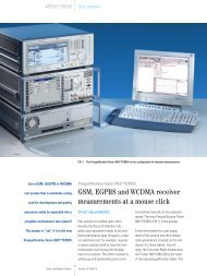
Universal Radio Communication Tester R&S CMU200<br />
Receiver measurements on<br />
GPRS and EGPRS mobile phones<br />
What UMTS holds for the future<br />
is already materializing in GSM<br />
networks: high-speed data transmission.<br />
This is made possible with the<br />
2.5G standards GPRS and EGPRS.<br />
While EGPRS mobile phones are<br />
still in the development stage, GPRS<br />
mobiles are already on the market.<br />
The new 2.5G standards mean new<br />
measurement challenges for manufacturers<br />
of mobile phones. For<br />
example, new approaches have to be<br />
taken in receiver measurements. The<br />
Universal Radio Communication Tester<br />
R&S CMU200 from <strong>Rohde</strong> & <strong>Schwarz</strong><br />
provides full receiver test capability<br />
not only for GPRS, but now for EGPRS<br />
mobile phones as well.<br />
See page 25 of this issue for<br />
another contribution on the<br />
R&S CMU200.<br />
GPRS/EGPRS packet-based<br />
data links<br />
In packet-based data transmission, an<br />
entire physical path will not generally be<br />
established between the communicating<br />
terminals throughout the time of communication.<br />
Rather, a link is set up only<br />
when data is actually transmitted. First,<br />
the base station agrees with the mobile<br />
phone on the timeslot(s) of the RF channel<br />
to be used for data exchange. A<br />
total of eight timeslots is available. The<br />
number of timeslots used depends on<br />
the multislot class of the mobile and<br />
on the base station loading. In addition,<br />
the mobile is assigned an uplink state<br />
flag (USF). The USF flag, which is transmitted<br />
by the base station in the downlink<br />
(DL), determines whether or not the<br />
mobile may send data in one of the corresponding<br />
uplink (UL) timeslots. Up to<br />
seven mobiles can in this way share a<br />
timeslot. Each time a mobile decodes its<br />
USF in a data block in a downlink timeslot,<br />
it may – and should – send a data<br />
block in the corresponding uplink timeslot<br />
in the subsequent radio link control<br />
(RLC) block frame if the mobile was<br />
assigned this uplink timeslot beforehand<br />
(FIG 1). If, at a given instance, the<br />
mobile has no user data to send in the<br />
uplink timeslot, it sends a dummy block<br />
instead. This addressing mode is known<br />
as dynamic allocation. However, if the<br />
mobile is assigned several uplink timeslots,<br />
this mode has the disadvantage<br />
that, for each uplink data block to be<br />
sent, the mobile first has to decode a<br />
downlink data block. The capabilities of<br />
today‘s mobiles, featuring only one synthesizer<br />
for the uplink and the downlink,<br />
are thus stretched to their limits,<br />
i.e. mobiles can handle no more than<br />
two uplink timeslots. For this reason,<br />
the extended dynamic allocation mode<br />
was introduced. With this addressing<br />
mode, the first valid USF flag received<br />
by the mobile is also valid for all uplink<br />
timeslots in the current RLC block frame<br />
(FIG 2). The addressing mode to be used<br />
in a packet-based data link is determined<br />
by the base station.<br />
Receiver measurements with<br />
packet-based data links<br />
Standardization bodies have defined<br />
the block error rate (BLER) as the relevant<br />
quantity for receiver measurements<br />
with packet-based data links. In GPRS<br />
or EGPRS systems, the mobile requests<br />
all errored data blocks received to be<br />
retransmitted. The BLER is the ratio of<br />
errored data blocks received (i.e. data<br />
blocks to be retransmitted) to the total<br />
number of data blocks transmitted. But<br />
the BLER is not the only receiver quantity<br />
of interest.<br />
There is, for example, the USF BLER.<br />
What does this quantity stand for?<br />
A mobile may send a data block in the<br />
uplink only if it has received a valid USF<br />
in the downlink. However, if the mobile<br />
does not correctly decode the USF, it will<br />
not send a data block in the corresponding<br />
uplink timeslot. The USF BLER designates<br />
the ratio of the number of incorrectly<br />
decoded USF flags to the total<br />
number of USF flags transmitted (FIG 3).<br />
BLER and USF BLER measurements are<br />
mandatory for conformance testing of<br />
GPRS and EGPRS mobiles. BLER measurements<br />
are problematic in production,<br />
however, since they are time-consuming<br />
and, by their very nature, may stop,<br />
so that measurement time is not reliably<br />
21<br />
News from <strong>Rohde</strong>&<strong>Schwarz</strong> Number 176 (2002/IV)