English - Rohde & Schwarz
English - Rohde & Schwarz
English - Rohde & Schwarz

Create successful ePaper yourself
Turn your PDF publications into a flip-book with our unique Google optimized e-Paper software.
GENERAL PURPOSE<br />
Test methods<br />
The happy medium:<br />
Signal Generator R&S SMV03<br />
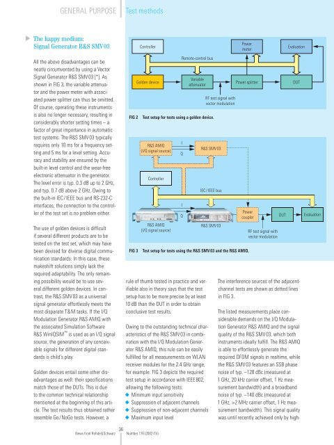
Controller<br />
Power<br />
meter<br />
Evaluation<br />
All the above disadvantages can be<br />
neatly circumvented by using a Vector<br />
Signal Generator R&S SMV03 [*]. As<br />
shown in FIG 3, the variable attenuator<br />
and the power meter with associated<br />
power splitter can thus be omitted.<br />
Of course, operating these instruments<br />
is also no longer necessary, resulting in<br />
considerably shorter setting times – a<br />
factor of great importance in automatic<br />
test systems. The R&S SMV03 typically<br />
requires only 10 ms for a frequency setting<br />
and 5 ms for a level setting. Accuracy<br />
and stability are ensured by the<br />
built-in level control and the wear-free<br />
electronic attenuator in the generator.<br />
The level error is typ. 0.3 dB up to 2 GHz,<br />
and typ. 0.7 dB above 2 GHz. Owing to<br />
the built-in IEC/IEEE bus and RS-232-C<br />
interfaces, the connection to the controller<br />
of the test set is no problem either.<br />
The use of golden devices is difficult<br />
if several different products are to be<br />
tested on the test set, which may have<br />
been devised for diverse digital communication<br />
standards. In this case, these<br />
makeshift solutions simply lack the<br />
required adaptability. The only remaining<br />
possibility would be to use several<br />
different golden devices. In contrast,<br />
the R&S SMV03 as a universal<br />
signal generator effortlessly meets the<br />
most disparate T&M tasks. If the I/Q<br />
Modulation Generator R&S AMIQ with<br />
the associated Simulation Software<br />
R&S WinIQSIM is used as an I/Q signal<br />
source, the generation of any conceivable<br />
signals for different digital standards<br />
is child’s play.<br />
Golden devices entail some other disadvantages<br />
as well: their specifications<br />
match those of the DUTs. This is due<br />
to the common technical relationship<br />
mentioned at the beginning of this article.<br />
The test results thus obtained rather<br />
resemble Go/NoGo tests. However, a<br />
FIG 2<br />
FIG 3<br />
Golden device<br />
R&S AMIQ<br />
(I/Q signal source)<br />
Controller<br />
R&S AMIQ<br />
(I/Q signal source)<br />
Remote-control bus<br />
I<br />
Q<br />
I<br />
Q<br />
Variable<br />
attenuator<br />
Test setup for tests using a golden device.<br />
rule of thumb tested in practice and verifiable<br />
also in theory says that the test<br />
setup has to be more precise by at least<br />
10 dB than the DUT in order to obtain<br />
conclusive test results.<br />
Owing to the outstanding technical characteristics<br />
of the R&S SMV03 in combination<br />
with the I/Q Modulation Generator<br />
R&S AMIQ, this rule can be easily<br />
fulfilled for all measurements on WLAN<br />
receiver modules for the 2.4 GHz range,<br />
for example. FIG 3 depicts the required<br />
test setup in accordance with IEEE802,<br />
allowing the following tests:<br />
◆ Minimum input sensitivity<br />
◆ Suppression of adjacent channels<br />
◆ Suppression of non-adjacent channels<br />
◆ Maximum input level<br />
RF test signal with<br />
vector modulation<br />
R&S SMV03<br />
IEC/IEEE bus<br />
R&S SMV03<br />
Power splitter<br />
Power<br />
coupler<br />
Test setup for tests using the R&S SMV03 and the R&S AMIQ.<br />
RF test signal with<br />
vector modulation<br />
DUT<br />
DUT<br />
The interference sources of the adjacentchannel<br />
tests are shown as dotted lines<br />
in FIG 3.<br />
The listed measurements place considerable<br />
demands on the I/Q Modulation<br />
Generator R&S AMIQ and the signal<br />
quality of the R&S SMV03, which both<br />
instruments ideally fulfill. The R&S AMIQ<br />
is able to effortlessly generate the<br />
required OFDM signals in realtime, while<br />
the R&S SMV03 features an SSB phase<br />
noise of typ. –128 dBc (measured at<br />
1 GHz, 20 kHz carrier offset, 1 Hz measurement<br />
bandwidth) and a broadband<br />
noise of typ. –140 dBc (measured at<br />
1 GHz, >2 MHz carrier offset, 1 Hz measurement<br />
bandwidth). This signal quality<br />
was until recently achieved only by high-<br />
Evaluation<br />
36<br />
News from <strong>Rohde</strong>&<strong>Schwarz</strong> Number 176 (2002/IV)