English - Rohde & Schwarz
English - Rohde & Schwarz
English - Rohde & Schwarz

You also want an ePaper? Increase the reach of your titles
YUMPU automatically turns print PDFs into web optimized ePapers that Google loves.
MOBILE RADIO<br />
Radiocommunication testers<br />
predictable [1]. Bit error rate (BER) measurements<br />
are, therefore, the much more<br />
viable alternative for production. BER<br />
measurements require a pseudo random<br />
data stream. They can be implemented<br />
by means of the GPRS test mode B<br />
defined by the standardization bodies.<br />
In this test mode, the mobile returns the<br />
data block received, so that the transmitted<br />
data stream can be compared with<br />
the received data stream and the BER<br />
determined. Unfortunately, standardization<br />
bodies originally only had transmitter<br />
measurements in mind when working<br />
out test mode B, and had not specified<br />
exactly what kind of data a mobile<br />
should return in response to an errored<br />
data block. Most of the mobiles presently<br />
available return dummy RLC blocks<br />
instead of the data received. This does<br />
not allow BER measurements, however.<br />
Test mode B was therefore modified by<br />
standardization bodies so that it can be<br />
used for BER measurements.<br />
One more test mode was defined for<br />
EGPRS mobiles: EGPRS switched radio<br />
block loopback mode (frequently also<br />
referred to as test mode C). In this mode,<br />
channel coding is omitted, leaving more<br />
data bits for BER measurement (comparable<br />
to burst-by-burst BER measurement<br />
in circuit-switched links). Mobiles<br />
capable of 8PSK EDGE modulation both<br />
in the uplink and the downlink return<br />
exactly as many data bits as they have<br />
received (FIG 4). By contrast, mobiles<br />
capable of handling 8PSK EDGE modulation<br />
only in the downlink and using<br />
GMSK modulation in the uplink are able<br />
to return only one third of the data bits<br />
received. To solve this problem, test<br />
equipment is allowed to transmit data<br />
blocks to such a mobile in every third<br />
RLC block frame only. The mobile will<br />
then return the data in three consecutive<br />
RLC block frames (FIG 5).<br />
Reduced signalling cuts down<br />
on test time<br />
In mobile phone production every millisecond<br />
of test time counts. Manufacturers<br />
therefore make every effort to<br />
reduce test time. A substantial reduction<br />
of measurement time can be achieved<br />
by omitting signalling sequences. These<br />
are irrelevant in production, as they<br />
are software based and therefore need<br />
not be tested on every mobile. Many<br />
mobile phone manufacturers have<br />
for this reason replaced GSM signalling<br />
sequences by proprietary mobile<br />
phone interfaces and commands, and<br />
expect their mobile radio test system to<br />
be capable of handling such reduced<br />
sequences [2].<br />
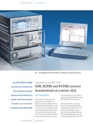
GPRS and EGPRS receiver measurements<br />
with R&S CMU200<br />
The Universal Radio Communication<br />
Tester R&S CMU200 performs all relevant<br />
receiver measurements on GPRS<br />
and EGPRS mobile phones, offering outstanding<br />
user convenience. For example,<br />
BLER is output separately for each<br />
time slot and as a total value over all<br />
timeslots used. The total data transmission<br />
rate achieved is also output<br />
(FIG 6). In test mode A, which is actually<br />
intended for transmitter tests only,<br />
the R&S CMU200 in addition determines<br />
the USF BLER. This is of interest especially<br />
for GPRS mobiles that only support<br />
test mode A. In test mode B, the<br />
R&S CMU200 calculates the BER as well<br />
as the USF BLER and the D(data)BLER<br />
(FIG 7). The DBLER is a calculated block<br />
error rate, which comes very close to<br />
the actual BLER [1]. The DBLER can be<br />
determined even if the mobile, in test<br />
mode B, only returns a dummy RLC block<br />
in response to an errored data block.<br />
The tester supports test modes A and B<br />
for GPRS also with reduced signalling<br />
sequences, thus cutting down on measurement<br />
time.<br />
For the figures shown opposite, the following should be noted:<br />
The frames comprising timeslots 0 to 7 are RLC block frames<br />
and should not be confused with GSM frames. Several GSM<br />
frames, i.e. several transmit bursts in a given timeslot, are<br />
needed to transmit one RLC data block.<br />
FIG 1<br />
Packet-based data transmission with dynamic allocation. On<br />
link setup, the base station agrees with the mobile on the<br />
timeslot(s) in which the mobile may send data and assigns a<br />
USF flag to the mobile. Several mobiles can be assigned identical<br />
timeslots and different USF flags (mobiles 1, 2 and 5 in<br />
this example) or identical USF flags and different timeslots<br />
(mobiles 3 and 4 in this example). The USF flags transmitted<br />
by the base station in the downlink are marked by different<br />
colours. The mobile receives the different USF flags. It will<br />
send a data packet each time it recognizes its own USF flag if<br />
the corresponding uplink timeslot is assigned to the mobile.<br />
FIG 2<br />
Packet-based data transmission with extended dynamic allocation.<br />
This mode functions the same as dynamic allocation.<br />
It differs from dynamic allocation only in that the first valid<br />
USF flag received is also valid for all following uplink timeslots<br />
assigned to the mobile in the current RLC block frame.<br />
FIG 3<br />
USF BLER: If a mobile decodes a USF flag incorrectly, it will<br />
not transmit a data packet in the corresponding uplink RLC<br />
timeslot. The USF BLER is the ratio of incorrectly decoded<br />
USF flags to the total number of USF flags transmitted. It is<br />
also possible that the mobile decodes a USF flag assigned<br />
to another mobile as its own flag. In such a case, the mobile<br />
would send a data packet in a wrong timeslot. This type of<br />
error, which is also measured, is frequently referred to as<br />
negative USF BLER.<br />
FIG 4<br />
In the symmetrical EGPRS switched radio block loopback<br />
mode, the mobile returns to the measuring instrument exactly<br />
as many data blocks (without channel coding) as it has<br />
received.<br />
FIG 5<br />
In the nonsymmetrical EGPRS switched radio block loopback<br />
mode, the mobile receives three times as many data bits<br />
as it can return. For this reason, the measuring instrument<br />
is allowed to transmit a valid data block to the mobile only<br />
in every third RLC block frame. The mobile returns the data<br />
block in three consecutive RLC block frames.<br />
22<br />
News from <strong>Rohde</strong>&<strong>Schwarz</strong> Number 176 (2002/IV)