English - Rohde & Schwarz
English - Rohde & Schwarz
English - Rohde & Schwarz

Create successful ePaper yourself
Turn your PDF publications into a flip-book with our unique Google optimized e-Paper software.
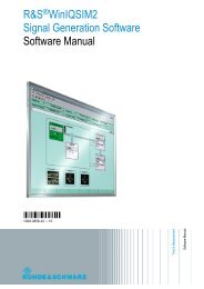
News from <strong>Rohde</strong> & <strong>Schwarz</strong><br />
Universal test platform<br />
for digital television<br />
Vector network analyzers<br />
for balanced measurements<br />
Up to the limits – new<br />
benchmark in audio analysis<br />
2004/III<br />
183
NUMBER 183 2004/III Volume 44<br />
The combination of Internet and broadcast technologies<br />
is creating new multimedia services for<br />
mobile phone owners: DVB-H will be the basis<br />
for future mobile IP-based datacasting applications.<br />
As a result, video streaming will soon be<br />
available for mobile battery-operated devices.<br />
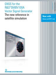
The new Broadcast Test System R&S®SFU fully<br />
integrates the DVB-H standard with DVB-T.<br />
But the R&S®SFU has a lot more to offer: It is a<br />
comprehensive system for all TV test and measurement<br />
applications (page 39).<br />
44240<br />
MOBILE RADIO<br />
Radiocommunication testers<br />
Universal Radio Communication Tester R&S ® CMU200<br />
HSDPA – accelerator for WCDMA ....................................................................................4<br />
TETRA radio systems<br />
TETRA Mobile Radio System ACCESSNET®-T<br />
Reliable use on oil fields all over the world .....................................................................7<br />
GENERAL PURPOSE<br />
Network analyzers<br />
Vector Network Analyzers R&S ® ZVB<br />
Fast network analyzers – also for balanced measurements ..........................................10<br />
The R&S®ZVB family is a new generation of<br />
vector network analyzers for universal measurements<br />
– also on multiports and balanced DUTs<br />
(page 10).<br />
Audio analyzers<br />
Audio Analyzer R&S ® UPV: The benchmark in audio analysis ........................................16<br />
Spectrum analyzers<br />
Spectrum Analyzer R&S ® FSU50<br />
Excellent measurement accuracy up to 50 GHz and higher ...........................................21<br />
Spectrum and Signal Analyzers R&S ® FSP / FSU / FSQ<br />
Extended measurement functions for analog modulation analysis ...............................24<br />
Signal analyzers<br />
Signal Analyzer R&S ® FSQ40: Signal analysis now up to 40 GHz ...................................26<br />
Signal Analyzer R&S ® FSQ<br />
The complete family of wireless LAN standards: 802.11 a, b, g, j, n .............................28<br />
Expanded recording length for vector signal analysis ....................................................31<br />
The Audio Analyzer R&S®UPV sets absolutely<br />
new standards in audio test and measurement<br />
(page 16).<br />
News from <strong>Rohde</strong> & <strong>Schwarz</strong><br />
2<br />
Controllers<br />
Industrial Controller R&S ® PSL1<br />
Compact yet sophisticated ..............................................................................................32<br />
Number 183 (2004/III)
Power meters<br />
New Power Sensors for R&S ® NRP, NRT und FSH<br />
When it comes to power measurements, a reliable sensor is a must ...........................34<br />
Signal generators<br />
Vector Signal Generator R&S ® SMU200A<br />
Complex signal scenarios at almost no effort .................................................................36<br />
BROADCASTING<br />
Test systems<br />
Broadcast Test System R&S ® SFU<br />
Universal test platform for digital TV ..............................................................................39<br />
Datacasting<br />
MHP ObjectCarousel R&S ® MHPCAR<br />
More than picture and sound: multimedia TV ................................................................44<br />
The Broadcast Test System R&S®SFU covers<br />
virtually all areas of digital TV: research and<br />
development, production, quality assurance,<br />
service, propagation and reception tests performed<br />
by network operators as well as EMC<br />
measurements (page 39).<br />
Monitoring systems<br />
MPEG-2 Monitoring System R&S ® DVM50<br />
Cost-efficient monitoring of up to two transport streams ..............................................47<br />
Reference<br />
DVB-T in Germany – the second setup phase is in full swing .......................................50<br />
FOCUS<br />
Software defined radios<br />
Software defined radios – software aspects and the future (2) ....................................52<br />
RADIOMONITORING<br />
Reference<br />
VHF/UHF DF network of German Regulatory Authority<br />
for Post and Telecommunication subject to nationwide modernization ........................56<br />
MISCELLANEOUS<br />
Newsgrams ......................................................................................................................58<br />
The German Regulatory Authority for Post<br />
and Telecommunication (RegTP) operates the<br />
Direction Finders R&S DDF®0xM to carry out its<br />
governmental tasks (page 56).<br />
News from <strong>Rohde</strong> & <strong>Schwarz</strong><br />
3<br />
Published by <strong>Rohde</strong>&<strong>Schwarz</strong> GmbH&Co. KG · Mühldorfstrasse 15 · 81671 München<br />
Support Center: Tel. (+49) 01805124242 · E-mail: customersupport@rohde-schwarz.com<br />
Fax (+4989) 4129-13777 · Editor and layout: Ludwig Drexl, Redaktion – Technik (German)<br />
<strong>English</strong> translation: Dept. 9UK7 · Photos: <strong>Rohde</strong>&<strong>Schwarz</strong> · Circulation (German, <strong>English</strong>, French, Russian<br />
and Chinese) 90000 approx. 4 times a year · ISSN 0028-9108 · Supply free of charge through your nearest<br />
<strong>Rohde</strong>&<strong>Schwarz</strong> representative · Printed in Germany by peschke druck, München · Reproduction of extracts<br />
permitted if source is stated and copy sent to <strong>Rohde</strong>&<strong>Schwarz</strong> München.<br />
R&S® is a registered trademark of <strong>Rohde</strong>&<strong>Schwarz</strong> GmbH&Co. KG. Trade names are trademarks of the owners. CDMA2000® is a registered<br />
trademark of Telecommunications Industry Association (TIA USA). The Bluetooth word mark and logos are owned by the Bluetooth SIG, Inc.<br />
and any use of such marks by <strong>Rohde</strong>&<strong>Schwarz</strong> is under license.<br />
Number 183 (2004/III)
MOBILE RADIO<br />
Radiocommunication testers<br />
Universal Radio Communication Tester R&S ® CMU200<br />
HSDPA – accelerator for WCDMA<br />
HSDPA 1) , the expansion of WCDMA 2)<br />
in third-generation mobile radio,<br />
increases transmission rates in data<br />
links from base stations to UMTS user<br />
equipment to more than 10 Mbit/s.<br />
Such high transfer rates allow fast<br />
loading of videos to mobile radio<br />
equipment, for example.<br />
This article examines new principles<br />
that are being applied to expand a<br />
defined mobile radio standard in this<br />
way, and which requirements they<br />
place on T&M equipment.<br />
Faster with HSDPA<br />
WCDMA FDD (frequency division duplex)<br />
was designed for a useful data rate of<br />
384 kbit/s, or 2 Mbit/s if the multiple<br />
code method is used. If the chip rate<br />
on the air interface remains unchanged<br />
(3.84 Mchip/s), up to 14.4 Mbit/s can<br />
additionally be transmitted in HSDPA<br />
channels in the downlink. This is feasible<br />
because of the highly sophisticated<br />
communications principles applied in<br />
the lower layers (physical layer and MAC<br />
layer) of the two communicating partners,<br />
i.e. the base station and the mobile<br />
radio user equipment.<br />
The key elements of this new standard<br />
are as follows:<br />
◆ Intelligent use and reduction of<br />
frames for information units from<br />
10 ms (15 timeslots) to 2 ms (three<br />
timeslots).<br />
◆ Optional use of a higher-level modulation<br />
mode (16QAM).<br />
◆ Fast and optimized adaptation of<br />
modulation, channel coding and<br />
power in the downlink (adaptive modulation<br />
and error coding) to meet current<br />
radio channel conditions.<br />
◆ Continuous and fast feedback of the<br />
reception quality in the user equipment<br />
(channel quality indication –<br />
CQI).<br />
◆ Short response times have been<br />
defined in the physical layer of the<br />
mobile radio user equipment. During<br />
this time, the equipment acknowledges<br />
whether an HSDPA data packet<br />
was “understood” (ACK/NACK process).<br />
◆ Information retransmission with<br />
changed coding (incremental redundancy):<br />
The mobile radio user equipment<br />
intelligently superimposes fragments<br />
that were received at different<br />
times (soft combining) and thus tries<br />
to decode the complete information.<br />
◆ Division of the transmission subframes<br />
into parallel processes that<br />
are controlled independently of<br />
each other (hybrid automatic repeat<br />
request – HARQ).<br />
HSDPA expands the channel structure<br />
of the previous WCDMA system (FIG 1).<br />
User equipment for HSDPA processes<br />
up to four control channels (HS-SCCH)<br />
in addition to the known physical channels<br />
of a WCDMA cell in the down-<br />
Base station<br />
Downlink DPCH<br />
Shared control channel (HS-SCCH) 1<br />
DUT<br />
Modulation/<br />
code assignment<br />
FEC<br />
Shared control channel (HS-SCCH) 2<br />
Shared control channel (HS-SCCH) 3<br />
Data<br />
Shared control channel (HS-SCCH) 4<br />
1) High-speed downlink packet access.<br />
2) Wideband code division multiple access.<br />
FIG 1<br />
Channel structure of<br />
the physical channels<br />
with HSDPA.<br />
HS-PDSCH<br />
Uplink DPCH<br />
HS-DPCCH<br />
ACK / NACK,<br />
quality index<br />
News from <strong>Rohde</strong> & <strong>Schwarz</strong><br />
4<br />
Number 183 (2004/III)
HS-DSCH<br />
category<br />
Max. number<br />
of HS-DSCH<br />
codes that can<br />
be received<br />
Min. intertime<br />
transmission<br />
interval<br />
Max. number of bits in<br />
an HS-DSCH transport<br />
block during an<br />
HS-DSCH TTI<br />
Total number<br />
of soft channel<br />
bits<br />
1 (1.2 Mbit/s) 5 3 7298 19200<br />
2 5 3 7298 28800<br />
3 5 2 7298 28800<br />
4 5 2 7298 38400<br />
5 (3.6 Mbit/s) 5 1 7298 57600<br />
6 5 1 7298 67200<br />
7 (7 Mbit/s) 10 1 14411 115200<br />
8 10 1 14411 134400<br />
9 (10 Mbit/s) 15 1 20251 172800<br />
10 15 1 27952 172800<br />
11 (QPSK only) 5 2 3630 14400<br />
12 (QPSK only) 5 1 3630 28800<br />
FIG 2<br />
Categories for HSDPA mobile radio user equipment.<br />
link. Each channel contains information<br />
about which user equipment (user<br />
equipment identity – UE ID) is addressed<br />
by the HSDPA transmission and where<br />
the data packet that is transmitted a<br />
few moments later can be found in the<br />
code domain. Plus, the control channel<br />
describes the modulation and coding<br />
that are used and indicates whether this<br />
information is new or a repetition of a<br />
previously transmitted packet.<br />
The carriers for the coded and modulated<br />
payload are the HS-PDSCH channels,<br />
each of which physically occupies<br />
the same space in the code domain<br />
since they are spread with a fixed factor<br />
(SF = 16). A base station can distribute<br />
a maximum of 15 HS-PDSCH channels<br />
during a transmission to one or more<br />
units of user equipment.<br />
The transmission of the control channels<br />
and of the associated data channels<br />
requires three timeslots each, i.e. 2 ms.<br />
It should be noted that the data identifier<br />
on the HS-PDSCH channels starts<br />
with the third timeslot of the HS-SCCH<br />
channel, so there is a time overlap. Thus,<br />
the receiver in the mobile radio UE must<br />
start processing data even before it<br />
receives all the control information it<br />
requires.<br />
The 3GPP standard divides mobile user<br />
equipment into different categories on<br />
the basis of HSDPA performance (FIG 2).<br />
The categories indicate which transport<br />
block size the equipment offers (a<br />
quantity for the maximum information<br />
data rate), whether the equipment supports<br />
16QAM, the maximum number of<br />
HS-PDSCH channels the equipment can<br />
handle and how often the equipment is<br />
able to process HSDPA packets consecutively<br />
(minimal inter-time transmission<br />
interval – TTI).<br />
FIG 3<br />
Uplink<br />
DPCH<br />
HS-PDSCH<br />
in the DUT<br />
Uplink<br />
HS-DPCCH<br />
T slot = 2560 chips<br />
3 × T slot = 7680 chips<br />
As you can see from FIG 1, a new<br />
HS-DPCCH physical control channel<br />
has also been added to the uplink, i.e.<br />
the transmission from mobile radio<br />
UE to base station. This is the channel<br />
on which the mobile radio UE confirms<br />
whether it “understood” an HSDPA<br />
packet (acknowledged) or not (not<br />
acknowledged) so that the packet will<br />
be repeated if necessary. Moreover, the<br />
mobile radio UE continuously assesses<br />
the quality of the transmission path and<br />
cyclically transmits this information to<br />
the base station as a quality index (CQI)<br />
on this channel. Having this information,<br />
the base station can quickly define<br />
a favourable configuration for the downlink.<br />
The response time of an addressed<br />
mobile radio UE is precisely specified:<br />
no more than 5 ms after a message has<br />
been received (FIG 3).<br />
HSDPA with the R&S ® CMU200<br />
If the R&S ® CMU-K64 software option<br />
is added to a Universal Radio Communication<br />
Tester R&S ® CMU200 (featuring<br />
WCDMA functions), the tester can<br />
handle HSDPA signal generation and<br />
evaluation. At the generator end, you<br />
will find ready-to-use scenarios (fixed<br />
rate channel test, CQI test, etc) and configuration<br />
elements (e. g. parameter<br />
sets for HSDPA tests). These scenarios<br />
are derived from 3GPP documentation<br />
Slot 0 Slot 1 Slot 2 Slot 3 Slot 4 Slot 5 Slot 6 Slot 7 Slot 8 Slot 9 Slot 10Slot 11Slot 12<br />
m × 256 chips<br />
τ UEP ≈19200 chips<br />
Time correlation in the uplink and downlink (ACK/NACK processing time in the DUT ≈ 5 ms).<br />
3 × T slot = 7680 chips<br />
News from <strong>Rohde</strong> & <strong>Schwarz</strong><br />
5<br />
Number 183 (2004/III)
MOBILE RADIO<br />
Radiocommunication testers<br />
FIG 4<br />
Section of the<br />
HSDPA generator<br />
menu.<br />
for minimum DUT requirements (3GPP<br />
TS25.101) or, to some extent, from existing<br />
measurement procedures for RF conformance<br />
tests (3GPP TS34.121).<br />
For expert users, the R&S ® CMU200<br />
user interface offers downlink parameters<br />
that can be configured manually or<br />
via remote control. You can thus define<br />
basic parameters such as level and code<br />
channel, but also modulation mode<br />
(QPSK or 16QAM), number of HSDPA<br />
channels, transport block size, response<br />
in the case of retransmission and much<br />
more (FIG 4).<br />
UL DPCCH<br />
UL DPDCH<br />
HS DPCCH<br />
FIG 5<br />
Section of the<br />
HSDPA receiver<br />
quality menu.<br />
FIG 6<br />
Code domain<br />
measurement in<br />
the uplink: DCCH,<br />
DPDCH and<br />
HS-DPCCH.<br />
The R&S ® CMU-K64 software option in<br />
the receive section of the R&S ® CMU200<br />
includes evaluation of the HS-DCCH<br />
uplink channel. The tester decodes both<br />
the ACK/NACK fields and the CQI information,<br />
which it assigns on-screen to<br />
the matching transmission in the downlink.<br />
Within the instrument, the receiver<br />
in the R&S ® CMU200 forwards the control<br />
data to the transmitter, thus defining<br />
the characteristics of the next downlink<br />
transmissions. The complex and timecritical<br />
interaction between transmitter<br />
and receiver on the tester end must run<br />
smoothly to ensure dynamic testing. This<br />
is the only way to evaluate the quality of<br />
operations such as retransmissions for<br />
various test signals and to measure data<br />
throughput, for example (FIG 5).<br />
In addition to the HSDPA-specific tests<br />
described above, the required expansion<br />
of the existing RF test technology in<br />
the uplink is also worth mentioning. The<br />
modulation and code domain evaluation<br />
in the R&S ® CMU200 functions correctly<br />
irrespective of whether the additional<br />
uplink HS-DPCCH channel is present<br />
or not and evaluates the quality of<br />
the transmitter in the DUT (FIG 6).<br />
Pirmin Seebacher<br />
News from <strong>Rohde</strong> & <strong>Schwarz</strong><br />
6<br />
Number 183 (2004/III)
MOBILE RADIO<br />
TETRA radio systems<br />
TETRA Mobile Radio System ACCESSNET®-T<br />
Reliable use on oil fields<br />
all over the world<br />
Digital ACCESSNET ®-T TETRA mobile<br />
radio systems from <strong>Rohde</strong> & <strong>Schwarz</strong><br />
have long been meeting the most<br />
stringent of requirements on oil fields<br />
in Russia – including Siberia –, Libya,<br />
Algeria, Oman, Saudi Arabia, the<br />
Ukraine and Kuwait.<br />
A true test of communications<br />
equipment<br />
Crude oil, often referred to as black gold,<br />
is more important than ever; the entire<br />
world economy depends on a regular oil<br />
supply. This explains the high demands<br />
that are placed on technical facilities to<br />
be used in oil extraction, processing and<br />
transport. Security and availability are<br />
top priorities, and this also applies to<br />
communications equipment, which must<br />
function reliably even if environmental<br />
conditions are highly adverse, e. g.<br />
at extreme temperatures or in sandy or<br />
humid areas. Moreover, individual components<br />
must satisfy a key requirement:<br />
approval for use in explosion-prone environments.<br />
Digital ACCESSNET ®-T TETRA mobile<br />
radio systems from <strong>Rohde</strong> & <strong>Schwarz</strong> [*]<br />
have long featured a flexible system<br />
design, sophisticated redundancy capabilities<br />
and high applications compatibility.<br />
Thus, they long ago met all requirements<br />
for being deployed in the world’s<br />
oil industry (FIG 1).<br />
FIG 1 Communications facilities for oil fields must satisfy the highest of requirements yet be flexibly adaptable to diverse tasks. ACCESSNET ®-T is the<br />
ideal solution.<br />
Communications solutions for oil and gas companies<br />
Intrinsically safe portable terminals<br />
Naval communications<br />
BS BS BS<br />
Gateway<br />
MW<br />
Radio coverage along the pipeline<br />
SW<br />
BS<br />
Harbour area<br />
Microwave<br />
link<br />
Shortwave link<br />
Oil extraction<br />
MW<br />
TETRA<br />
BS<br />
BS<br />
NMS<br />
A-CAPI<br />
TETRA<br />
PABX<br />
Gateway<br />
TRD<br />
BS<br />
BS<br />
Refinery<br />
News from <strong>Rohde</strong> & <strong>Schwarz</strong><br />
7<br />
Number 183 (2004/III)
MOBILE RADIO<br />
TETRA radio systems<br />
Flexible system design –<br />
100% redundant<br />
PMR systems, one of which is<br />
ACCESSNET ®-T, were specifically developed<br />
for security-related operations.<br />
To satisfy demanding requirements,<br />
100% redundancy can be achieved<br />
with ACCESSNET ®-T: the exchange<br />
(R&S ® DMX), base stations (R&S ® DTX)<br />
and systems equipment are provided<br />
in duplicate. In the unlikely event that<br />
one of the network elements fails, the<br />
redundant component will immediately<br />
handle the defective element’s function.<br />
Even if a connecting line is interrupted,<br />
the communications system will not fail<br />
because all network elements are connected<br />
in duplicate.<br />
A line network is better suited for communications<br />
along a pipeline than<br />
any other structure. The multiplexers<br />
integrated in the base stations from<br />
<strong>Rohde</strong> & <strong>Schwarz</strong> permit a highly costefficient<br />
setup of such line structures;<br />
external multiplexers are not required.<br />
Customized solutions<br />
A “communications solution” would<br />
be the most appropriate and comprehensive<br />
description of the<br />
ACCESSNET ®-T TETRA mobile radio<br />
system from <strong>Rohde</strong>&<strong>Schwarz</strong>, since<br />
its unique A-CAPI application interface<br />
provides numerous ways to economically<br />
achieve customer-specific solutions.<br />
These include, for example, the following<br />
applications that <strong>Rohde</strong> & <strong>Schwarz</strong> has<br />
implemented for the oil industry all over<br />
the world:<br />
Automatic vehicle location<br />
If service or maintenance work becomes<br />
necessary, it is useful and, in emergency<br />
cases, even indispensable to know the<br />
whereabouts of the service personnel<br />
so they can be efficiently deployed. The<br />
coordinates of their whereabouts are<br />
determined by GPS receivers that are<br />
connected to the TETRA user equipment<br />
via the PEI interface and are then<br />
transmitted to the control center via<br />
ACCESSNET ®-T. Here, the locations of<br />
the vehicles are displayed on a map<br />
on the monitor. The vehicle closest to<br />
the site of operation can be sent there<br />
immediately without losing valuable<br />
time.<br />
FIG 2 Service personnel on oil fields is often scattered across large areas. In such a case, it is<br />
beneficial if the operator works with ACCESSNET ®-T: The automatic system for vehicle location helps<br />
to efficiently coordinate operational forces.<br />
Remote monitoring system<br />
Usually, oil extraction systems, pipelines,<br />
loading stations and refineries are<br />
located at large distances from each<br />
other. A high number of staff would be<br />
necessary to handle the numerous controlling<br />
and monitoring tasks across<br />
these distances. Even more critical are<br />
emergency situations. In such a case, it<br />
would be impossible to take countermeasures<br />
in time without specific technical<br />
precautions.<br />
Photo: R&S BICK Mobilfunk GmbH<br />
With ACCESSNET ®-T from<br />
<strong>Rohde</strong>&<strong>Schwarz</strong>, you are on the safe<br />
side when performing such tasks,<br />
because ACCESSNET ®-T can be complemented<br />
with the RMS telemetry<br />
system from <strong>Rohde</strong> & <strong>Schwarz</strong>, which<br />
is a controlling and monitoring system<br />
that exchanges messages and commands<br />
via a mobile radio system. For<br />
example, if pressure loss occurs in a<br />
pipeline, the valve leading to it can be<br />
closed from a distance. In another scenario,<br />
the system sends an alarm to<br />
the control center if a remote space is<br />
entered without authorization. These<br />
News from <strong>Rohde</strong> & <strong>Schwarz</strong><br />
8<br />
Number 183 (2004/III)
few examples show the outstanding<br />
importance <strong>Rohde</strong> & <strong>Schwarz</strong> attaches<br />
to operational reliability. A SCADA interface<br />
has recently been provided for<br />
ACCESSNET ®-T to connect it to other<br />
remote monitoring systems.<br />
Voice recording system<br />
The key features of ACCESSNET ®-T<br />
include security for voice and data transmission<br />
as well as the system’s operational<br />
reliability. Nevertheless, malfunctions<br />
in operating processes cannot<br />
always be prevented. In this event, a<br />
voice recording system can seamlessly<br />
reproduce communications. For recording<br />
purposes, <strong>Rohde</strong> & <strong>Schwarz</strong> uses<br />
the TETRA-coded signal with streams of<br />
8 kbit/s and is thus able to simultaneously<br />
record up to 240 channels on one<br />
E1 line (2 Mbit/s). In addition to voice,<br />
user data such as SDS (short data service<br />
with TETRA) is also recorded. Compared<br />
to previous methods, this method<br />
is eight times more effective and minimizes<br />
the investment required. The minimum<br />
storing capacity is another advantage.<br />
TETRA feature DGNA<br />
Operators of pipelines, oil fields and<br />
similar facilities do everything in their<br />
power to prevent emergencies. If an<br />
emergency situation occurs all the<br />
same, service and maintenance staff,<br />
rescue teams and security staff must<br />
work hand in hand without any difficulties.<br />
ACCESSNET ®-T provides the ideal<br />
support.<br />
Communications within TETRA networks<br />
occur mainly in group mode, i.e. groups<br />
are formed for teams that are working<br />
together such as service teams or rescue<br />
teams. There may even be several<br />
groups with the same tasks but at different<br />
locations. In cases of emergency, the<br />
control center, using the R&S ® TRD-500<br />
dispatcher system, can now very quickly<br />
bring together any individual subscribers<br />
from the existing groups to form a<br />
special task group which can then be<br />
addressed by a newly assigned group ID.<br />
ACCESSNET ®-T informs the subscribers<br />
about their new group assignment<br />
via the air interface and is immediately<br />
available upon reception. If a unit needs<br />
to be temporarily switched off, e. g. for<br />
changing the batteries, the received<br />
information will still be available.<br />
Summary<br />
The ACCESSNET ®-T mobile radio<br />
system complies with the TETRA standard,<br />
which was initially defined for<br />
use by government authorities and<br />
organizations with security missions.<br />
ACCESSNET ®-T has proven itself not only<br />
in the area of public safety but is also<br />
used in the oil industry, the military as<br />
well as local public transport and industrial<br />
companies. ACCESSNET ®-T is the<br />
ideal solution for all of these organizations<br />
because they all have the same<br />
requirement – maximum safety and<br />
reliability under any conditions. When<br />
particularly sensitive applications are<br />
involved, ACCESSNET ®-T is also available<br />
with encryption mode.<br />
Harald Haage<br />
Abbreviations<br />
More information and data sheet at<br />
www.rohde-schwarz.com<br />
(search term: ACCESSNET)<br />
LITERATUR<br />
[*] ACCESSNET ®-T – the digital mobile radio<br />
system from <strong>Rohde</strong> & <strong>Schwarz</strong>. News<br />
from <strong>Rohde</strong> & <strong>Schwarz</strong> (2003) No. 178,<br />
pp 6–13<br />
News from <strong>Rohde</strong> & <strong>Schwarz</strong><br />
A-CAPI ACCESSNET ®-T common application programming interface<br />
BS<br />
Base station<br />
DGNA Dynamic group number assignment; a function that allows authorized users of<br />
a TETRA system to dynamically set up or modify groups; information is transmitted<br />
via the air interface to the relevant user equipment<br />
NMS Network management system, for subscriber management, configuration,<br />
data acquisition, service and maintenance in ACCESSNET ®-T systems.<br />
PABX Private automatic branch exchange<br />
PEI Peripheral equipment interface; for applications (ETS 300 392-5)<br />
PMR Professional mobile radio<br />
RMS Radio monitoring system; telemetry system from R&S BICK Mobilfunk<br />
SCADA Supervisory control and data acquisition; management and process visualization<br />
systems; fulfill versatile tasks for visualizing, controlling and integrating<br />
technical facilities<br />
TRD-500 Trunked radio dispatcher (R&S BICK Mobilfunk product designation)<br />
9<br />
Number 183 (2004/III)
GENERAL PURPOSE<br />
Network analyzers<br />
44297/5<br />
FIG 1<br />
The new Vector Network Analyzer R&S ® ZVB, here with four-port configuration.<br />
Vector Network Analyzers R&S ® ZVB<br />
Fast network analyzers –<br />
also for balanced measurements<br />
The R&S ® ZVB family is a new<br />
generation of vector network<br />
analyzers for universal measurements<br />
– also on multiports and balanced<br />
DUTs. Featuring outstanding<br />
specifications, high measurement and<br />
data transfer speed plus various data<br />
evaluation capabilities, they are ideal<br />
for use in development and production.<br />
Versatile, fast and compact<br />
The R&S ® ZVB family consists of two- and<br />
four-port models, ranging from 300 kHz<br />
to 4 GHz or to 8 GHz respectively (FIG 1).<br />
The frontend receivers use a fundamental<br />
mixing concept that has already been<br />
a success with the R&S ® ZVR family and<br />
which ensures a wide dynamic range of<br />
typ. 130 dB as well as low trace noise<br />
at large measurement bandwidths. The<br />
receivers exhibit a high compression<br />
point. At each measurement port, the<br />
maximum output power exceeds 13 dBm<br />
(typ. 16 dBm to 4 GHz). The output level<br />
can be electronically varied over 50 dB<br />
so that nonlinear parameters of active<br />
components can be determined quickly<br />
and without wear. In addition to RF test<br />
ports with bias tees for feeding active<br />
components, the R&S ® ZVB has two<br />
other inputs at the rear for measuring<br />
low-frequency AC voltages.<br />
The R&S ® ZVB family offers considerably<br />
more display and evaluation capabilities<br />
than its predecessors. The number of<br />
test points per trace has been increased<br />
to 20001, and the sum of the traces<br />
and diagrams is limited only by memory.<br />
Several channels can be created in the<br />
R&S ® ZVB for testing DUTs under various<br />
operating conditions. A channel contains<br />
all settings by means of which the<br />
analyzer samples the data of the DUT,<br />
such as sweep type (frequency, level,<br />
etc), number of test points, source level,<br />
IF bandwidth or the calibration. Several<br />
traces can be assigned to each channel,<br />
to simultaneously display, for example,<br />
10<br />
News from <strong>Rohde</strong> & <strong>Schwarz</strong> Number 183 (2004/III)
S-parameters, output power, DC power<br />
consumption or stability factors under<br />
different operating conditions.<br />
Simple operating concept for<br />
stress-free work in the lab<br />
Complex measurement tasks in network<br />
analysis, especially with multiport<br />
applications, call for an intuitive<br />
and straightforward user interface. The<br />
R&S ® ZVB has a great advantage since<br />
it allows you to easily handle even the<br />
most demanding of measurement tasks<br />
despite the numerous ports, measurement<br />
parameters, diagrams and traces<br />
as well as extensive functions. Its easyto-grasp<br />
concept is especially beneficial<br />
for untrained or infrequent users.<br />
But even network analysis experts will<br />
appreciate the sophisticated and intuitive<br />
user interface.<br />
FIG 3<br />
If you click on the<br />
right-hand mouse<br />
button, contextsensitive<br />
menus<br />
open up.<br />
FIG 2<br />
Identical structures in<br />
front-panel and mouse<br />
operation.<br />
In addition to the tried-and-tested operation<br />
via hardkeys and softkeys, the<br />
R&S ® ZVB also provides a Windows®-like<br />
user interface and can be fully mouseoperated<br />
using pull-down menus. The<br />
mouse operation and the hardkey/softkey<br />
concept share identical structures so<br />
that you will find all functions at exactly<br />
the same positions both in the pull-down<br />
and in the softkey menus (FIG 2).<br />
FIG 4<br />
With the R&S ® ZVB,<br />
you can load<br />
several setups<br />
and then quickly<br />
switch between<br />
them.<br />
With the aid of dialogs, you can conveniently<br />
manage high numbers of measurement<br />
ports, measurement parameters<br />
and traces. User-friendly wizards in<br />
the R&S ® ZVB support complex operating<br />
sequences such as calibration or measurements<br />
on balanced devices.<br />
Unlike numerous other network analyzers<br />
on the market, the R&S ® ZVB allows<br />
you to quickly configure the display by<br />
arbitrarily assigning traces to specific<br />
diagrams and channels with only a few<br />
keystrokes and without complicated<br />
menu changes.<br />
11<br />
News from <strong>Rohde</strong> & <strong>Schwarz</strong> Number 183 (2004/III)
GENERAL PURPOSE<br />
Network analyzers<br />
FIG 7 Using the calibration unit (here the four-port<br />
model), the R&S ® ZVB can be automatically calibrated<br />
at all ports within 20 seconds.<br />
FIG 5 The support keys – powerful aid<br />
for difficult measurements.<br />
FIG 6<br />
Using the mathematical editor,<br />
traces with complex mathematical<br />
functions can be linked.<br />
44246<br />
FIG 8<br />
Examples of balanced<br />
components.<br />
+<br />
DUT<br />
Differential-mode<br />
stimulus<br />
Common-mode<br />
stimulus<br />
FIG 9 Common-mode signals generated by<br />
mode conversion.<br />
Port 1 Port 2<br />
Differentialmode<br />
response<br />
Commonmode<br />
response<br />
Port 1<br />
Port 2<br />
Port 1<br />
Port 2<br />
Port 1 Port 2<br />
Port 1 Port 2<br />
S cd 21 S cd 22 S cc 21<br />
Sdd 11 Sdd 12<br />
Sdc 11 Sdc 12<br />
S dd 21 S dd 22<br />
S dc 21 S dc 22<br />
Scd 11 Scd 12<br />
Scc 11 Scc 12<br />
Condensed data of the R&S ® ZVB<br />
Frequency range<br />
300 kHz to 4 GHz (R&S ® ZVB4)<br />
300 kHz to 8 GHz (R&S ® ZVB8)<br />
Number of test ports 2 or 4<br />
Dynamic range at 10 Hz<br />
>123 dB up to 4 GHz<br />
Bandwidths<br />
1 Hz to 500 kHz<br />
Number of test points<br />
20001 per trace<br />
Measurement time with 201 points and<br />
500 kHz IF bandwidth
If you prefer using the mouse, you will<br />
quickly find all necessary functions without<br />
having detailed knowledge of the<br />
hardkey and softkey menu structure: By<br />
clicking on a screen element with the<br />
right-hand mouse button, you open the<br />
required context-sensitive menu (FIG 3).<br />
You can assign meaningful individual<br />
names to the numerous possible traces,<br />
measurement channels and markers to<br />
keep an overview.<br />
You can load different complete instrument<br />
setups – in Windows® applications<br />
they are called files – to memory<br />
(FIG 4). With manual operation, you<br />
then use the mouse and simply select<br />
from among the windows of the loaded<br />
setups. With remote control, this setup<br />
swapping considerably reduces the time<br />
for switching between the different<br />
setups. Since, in this case, the data of all<br />
loaded setups, including the calibration<br />
data, is already in memory, switching<br />
between these instrument setups takes<br />
no more than 10 ms. This is no time at<br />
all considering that recalling setups from<br />
the hard disk previously took up to one<br />
second in most cases.<br />
Auxiliary functions such as online help,<br />
retrieving information via hardware, or<br />
current measurement setups are available<br />
as hardkeys (FIG 5). The contextsensitive<br />
online help is part of the software<br />
update and thus always state-ofthe-art.<br />
A completely new feature is the<br />
R&S ® ZVB’s ability to reverse several<br />
operating steps by using the UNDO key.<br />
This even applies to presets. Time-consuming<br />
reconfigurations of instrument<br />
setups after an operator mistake are<br />
now a thing of the past.<br />
The R&S ® ZVB provides extensive functions<br />
for reading measurement data in<br />
and out, processing it further and linking<br />
it with other trace data. It offers various<br />
formats for exporting measurement<br />
data: MatLab® or files compatible with<br />
the Advanced Design System ADS simulation<br />
program with the extension *.snp<br />
as well as ASCII, making the analyzer<br />
compatible with conventional simulation<br />
programs. Since the data of these files<br />
can be ported to memory traces, you can<br />
directly compare measurement traces<br />
on the network analyzer online with the<br />
data obtained from simulations.<br />
Moreover, a versatile mathematical<br />
editor permits nearly any links of the<br />
measurement traces with complex mathematical<br />
functions (FIG 6). The expressions<br />
generated can be stored and transferred<br />
to other instruments.<br />
Versatile innovative calibration<br />
methods<br />
The test set configuration in the<br />
R&S ® ZVB satisfies all requirements<br />
placed on today’s calibration methods.<br />
The analyzer provides a versatile portfolio<br />
of innovative calibration routines<br />
whose ease of operation, high measurement<br />
accuracy and special suitability for<br />
calibrations in test fixtures are outstanding.<br />
A calibration unit, available in different<br />
port number and connector type<br />
configurations, provides maximum calibration<br />
convenience and speed (FIG 7).<br />
After being connected to the USB interface,<br />
the calibration unit is immediately<br />
ready for operation, and it takes only<br />
20 seconds for the network analyzer to<br />
be automatically calibrated. Compared<br />
to conventional manual calibration, this<br />
method saves a lot of time and considerably<br />
minimizes the risk of operating<br />
errors, especially if a complete four-port<br />
calibration is required, for example for<br />
measuring balanced two-port devices.<br />
Balanced devices –<br />
conveniently measured<br />
The R&S ® ZVB comes with special features<br />
for measuring balanced or differential<br />
devices. Balanced devices such<br />
as amplifiers, filters and data bus systems<br />
are used to an increasing extent in<br />
mobile radio and the computer industry.<br />
Their advantages include lower sensitivity<br />
to EMI signals plus lower emission<br />
of EMI signals, thus helping to achieve<br />
higher integration density.<br />
The most common components are<br />
those with two balanced ports and those<br />
with one balanced and one single-ended<br />
port (FIG 8). Instead of a signal with<br />
ground reference, two signals with the<br />
same amplitude, but 180° phase shift,<br />
are fed to the input of balanced components;<br />
this operating mode is referred to<br />
as differential mode. An ideal balanced<br />
two-port that is fed at the input with a<br />
differential-mode signal or wave quantity<br />
generates only reflected and transmitted<br />
differential-mode wave quantities<br />
at its inputs and outputs. In practice,<br />
however, a DUT also generates commonmode<br />
wave quantities due to mode conversion.<br />
They exhibit the same amplitudes<br />
at a port and no phase shift (FIG 9).<br />
Mixed-mode S-parameters describe the<br />
transmission characteristics of such balanced<br />
components; a balanced twoport<br />
can be characterized by 16 of these<br />
parameters, for example. The matrix in<br />
FIG 10 consists of four quadrants, each<br />
of which indicates the different operating<br />
modes. The indices of the S-parameters<br />
describe the mode of the relevant<br />
wave quantity. For example, S dd21 characterizes<br />
the ratio of the transmitted differential-mode<br />
wave quantity at port 2<br />
to the differential-mode wave quantity<br />
injected into port 1. The first quadrant<br />
usually describes the ideal operation of<br />
the balanced two-port.<br />
13<br />
News from <strong>Rohde</strong> & <strong>Schwarz</strong> Number 183 (2004/III)
GENERAL PURPOSE<br />
Network analyzers<br />
FIG 11<br />
The S-parameter wizard (excerpt) conveniently guides you through complex measurements.<br />
The second and third quadrants characterize<br />
the mode conversion of the<br />
DUT where it converts differential-mode<br />
wave quantities into common-mode<br />
wave quantities and vice versa, i.e. they<br />
usually describe unwanted behaviour.<br />
The fourth quadrant indicates the ratio<br />
of transmitted or reflected commonmode<br />
wave quantities to common-mode<br />
wave quantities fed in at one of the<br />
ports.<br />
FIG 12<br />
Mixed-mode S-parameters of a diplex filter.<br />
FIG 13<br />
NEXT and unbalanced<br />
attenuation<br />
between two cable<br />
pairs.<br />
Since network analyzers have singleended<br />
ports, common- or differentialmode<br />
signals can neither be fed to DUTs<br />
nor directly measured. To characterize<br />
balanced components, baluns (balanced-unbalanced<br />
transformers) were<br />
previously used to generate and measure<br />
differential- and common-mode signals<br />
also with a single-ended network<br />
analyzer. However, this measurement<br />
method is unsuitable for higher frequencies<br />
since neither baluns of the quality<br />
required nor the necessary calibration<br />
standards are available. Therefore, a different<br />
approach is being taken. Instead<br />
of analyzing the balanced two-port with<br />
the aid of baluns with balanced signals,<br />
the balanced two-port is measured as<br />
a single-ended four-port with a (singleended)<br />
four-port network analyzer. The<br />
mixed-mode S-parameters can be calculated<br />
from the unbalanced S-parameters.<br />
Two physical ports of the network analyzer<br />
form a logical balanced port. Therefore<br />
a four-port network analyzer has to<br />
be used to measure a balanced two-port<br />
device.<br />
An S-parameter wizard in the R&S ® ZVB<br />
supports these highly complex measurement<br />
tasks. It conveniently takes you<br />
step by step through the measurement<br />
setups and, if required, also offers a suitable<br />
calibration method (FIG 11). Thus,<br />
you can configure the entire display of<br />
all 16 mixed-mode S-parameters errorfree<br />
in less than 30 seconds.<br />
14<br />
News from <strong>Rohde</strong> & <strong>Schwarz</strong> Number 183 (2004/III)
Multiport measurements<br />
Balanced measurements,<br />
mixed-mode S parameters<br />
Separate generator for each test port<br />
Parallel measurements<br />
Calibration techniques:<br />
– TOSM, TRL/LRL, TOM, TRM, TNA<br />
– Multiport calibration techniques<br />
– Model-adaptable standards<br />
Specifications<br />
Frequency ranges up to 4 GHz and 8 GHz, with two or four test ports<br />
Extremely fast measurement times<br />
with simultaneous data transfer<br />
Dynamic range >123 dB<br />
IF bandwidths 1 Hz to 500 kHz<br />
Level sweep range 50 dB<br />
Up to 20 001 points per trace<br />
Unlimited number of independent<br />
channels and traces<br />
Parallel loading of setups<br />
(preloading, setup swap)<br />
Operation via front-panel keys or<br />
mouse and keyboard<br />
Online help<br />
Measurement wizard<br />
Optimization of production sequences<br />
Examples of measurement<br />
using the R&S ® ZVB<br />
Measurements on SAW filters<br />
Matching networks transform the<br />
impedance of balanced components,<br />
such as high-impedance SAW filters,<br />
to the lower impedances of the circuit.<br />
Users and manufacturers of SAW filters<br />
are thus interested in the behaviour<br />
of these components together with the<br />
suitable matching network. With the aid<br />
of virtual (calculated) matching networks<br />
in the R&S ® ZVB, you can avoid time-consuming<br />
setup of these physical networks.<br />
The R&S ® ZVB measures the DUT without<br />
matching networks and mathematically<br />
adds these networks. The network<br />
analyzer virtually embeds the SAW filter<br />
into the desired ideal matching circuit,<br />
taking into consideration also different<br />
impedances for the differential and the<br />
common mode (FIG 12).<br />
of frequency or level. The high output<br />
power of typ. 16 dBm and the large<br />
sweep range of the source exceeding<br />
50 dB permit fast and wear-free<br />
(i.e. without switching mechanical level<br />
attenuators) amplifier measurements<br />
under different load conditions. In addition<br />
to the amplifier’s input power and<br />
output power, you also need to know<br />
the DC supply currents and voltages to<br />
measure the PAE. The R&S ® ZVB measures<br />
the DC supply currents and voltage<br />
with two DC inputs. One of the DC<br />
inputs tolerates a voltage range of ±10 V<br />
for measuring the supply voltage, the<br />
second a voltage range of ±1 V with<br />
a resolution ten times higher to measure<br />
small voltages that drop at a current<br />
sense resistor. The necessary proportion<br />
factors for the different test configurations<br />
can be entered by means of<br />
a dialog.<br />
The R&S ® ZVB can handle many traces<br />
and measurement channels, limited only<br />
by memory. Thus, all requested parameters<br />
can be displayed versus frequency<br />
and level virtually in realtime and<br />
adjusted, if required.<br />
Thilo Bednorz<br />
Measurements on symmetrical cables<br />
Since the applications of symmetrical<br />
cables extend to the GHz range, they can<br />
only be measured using virtual baluns.<br />
In addition to reflection and transmission<br />
parameters, knowledge of crosstalk<br />
and mode conversion between two different<br />
cable pairs is necessary. Differential-mode<br />
crosstalk between two cable<br />
pairs measured at the same cable end<br />
is referred to as NEXT (near-end crosstalk);<br />
the differential-mode crosstalk<br />
between two cable pairs, measured at<br />
distant cable ends, is referred to as FEXT<br />
(far-end crosstalk). The R&S ® ZVB with<br />
four ports determines these parameters<br />
quickly and easily (FIG 13).<br />
More information, product brochure and<br />
data sheet at<br />
www.rohde-schwarz.com<br />
(search term: ZVB)<br />
Vector Network Analyzers ¸ZVB<br />
Specifications R&S ® ZVB<br />
Measurements on amplifiers<br />
The R&S ® ZVB provides numerous features<br />
for measurements on amplifiers: In<br />
addition to S-parameters, it also determines<br />
output power, stability factors,<br />
power consumption, power added efficiency<br />
(PAE, quotient of generated RF<br />
power and consumed DC power), impedances<br />
and Z-parameters as a function<br />
Vector Network Analyzers ¸ZVB<br />
Product Brochure R&S ® ZVB<br />
15<br />
News from <strong>Rohde</strong> & <strong>Schwarz</strong> Number 183 (2004/III)
GENERAL PURPOSE<br />
Audio analyzers<br />
44187<br />
FIG 1<br />
The Audio Analyzer R&S ® UPV shows what is possible today in audio measurements.<br />
Audio Analyzer R&S ® UPV<br />
The benchmark in audio analysis<br />
High-resolution digital media such<br />
as audio DVD place extremely high<br />
requirements on T&M equipment. The<br />
new Audio Analyzer R&S ® UPV meets<br />
these requirements across the board –<br />
and also sets new standards in audio<br />
analysis.<br />
Up to the limits<br />
The Audio Analyzer R&S ® UPV (FIG 1) is<br />
a new compact instrument for any type<br />
of audio measurement. If you work in<br />
a studio or develop and produce hi-fi<br />
and audio equipment, the R&S ® UPV<br />
can handle any measurement task up to<br />
the limits of what is technically feasible.<br />
High-resolution digital media such as<br />
DVD can thus be mastered as perfectly<br />
as analog measurements up to 250 kHz.<br />
The analyzer’s outstanding technology<br />
is easy to operate and ready for future<br />
applications. For example, future audio<br />
interfaces can easily be added via plugin<br />
cards.<br />
The analyzer in the R&S ® UPV measures<br />
level, frequency, phase and distortion.<br />
It can perform fast and accurate<br />
frequency response measurements and<br />
simultaneously display the signals in<br />
the frequency and time domains. Moreover,<br />
it can replay audio signals via a<br />
loudspeaker and perform a wide range<br />
of other tasks. A digital filter bank with<br />
weighting filters and user-definable filters<br />
can handle virtually any requirement.<br />
The generator in the R&S ® UPV produces<br />
all signals up to 80 kHz required in<br />
the audio field, ranging from sinewave<br />
and intermodulation signals up to noise<br />
signals and multisine signals with several<br />
thousand single lines. If you need<br />
more, you can use the built-in arbitrary<br />
waveform generator or replay signals<br />
in WAV format from the hard disk.<br />
16<br />
News from <strong>Rohde</strong> & <strong>Schwarz</strong> Number 183 (2004/III)
All these signals can be output by using<br />
an additional digital equalizer with userdefinable<br />
nominal frequency response or<br />
filtered in the time domain.<br />
With the Digital Audio I/O R&S ® UPV-B2<br />
option, this variety of signals is also<br />
available at the digital audio interfaces<br />
(AES/EBU, S/P-DIF and optical). In addition,<br />
physical parameters such as level,<br />
jitter or sample frequency can be analyzed.<br />
Landmark analysis concept<br />
The entire analog measurement path<br />
from the input to the A/D converter and<br />
the DSP is truly dual-channel. In stereo<br />
measurements, this eliminates time-consuming<br />
switchover and settling operations.<br />
The R&S ® UPV performs all measurements<br />
using digital signal processing.<br />
Signals to be measured are first subjected<br />
to complex preprocessing (fineresolution<br />
levelling and fundamental<br />
rejection for distortion measurements)<br />
using analog measurement modules<br />
before they are digitized and fed to digital<br />
measurement routines. This concept<br />
FIG 2<br />
Numerous highlights<br />
◆ Measurement bandwidth up to<br />
250 kHz<br />
◆ Dual-channel signal processing for<br />
maximum measurement speed<br />
◆ Simultaneous performance of<br />
several measurements<br />
◆ Graphical representation of all<br />
measurement results (FIG 2)<br />
◆ FFT analysis up to 256 k points<br />
◆ Generator for all audio signals up<br />
to 80 kHz<br />
◆ Dual-channel analog generator<br />
◆ Sinewave up to 200 kHz<br />
◆ Filters for analyzer and generator<br />
◆ Digital audio interfaces with sampling<br />
rates from 30 kHz to 200 kHz<br />
◆ Plug-in cards for additional audio<br />
interfaces, e. g. for I 2 S<br />
allows a higher dynamic range than that<br />
offered by the internal 24-bit converter.<br />
It also ensures a level of performance<br />
and versatility that is far superior to that<br />
offered by pure analog or digital measuring<br />
instruments.<br />
The R&S ® UPV displays measurement results in easy-to-read numeric values and graphs.<br />
Analyzer operation and measurement<br />
methods are always the same no matter<br />
whether measurements are performed<br />
on analog or digital interfaces. This is<br />
truly a benefit for a variety of applications.<br />
For example, you can directly compare<br />
measurement results obtained in<br />
front of or after a converter. All measurement<br />
functions and test signals are<br />
available on both the analog and digital<br />
interfaces, enabling you to perform<br />
measurements at any point on a mixed<br />
analog/digital transmission path. This<br />
ensures efficient and comprehensive<br />
troubleshooting.<br />
Since digital measurement routines can<br />
continuously adapt their measurement<br />
speed to the current input frequency, far<br />
higher measurement speeds than those<br />
known for analog measurements are<br />
achieved.<br />
Wide range of measurement<br />
functions<br />
◆ Level, both selective and wideband<br />
with rms, peak or quasi-peak weighting.<br />
◆ S/N ratio<br />
◆ Distortions (harmonic distortion,<br />
THD+N, SINAD). The individual harmonics<br />
can be displayed as a bargraph,<br />
or the complete frequency<br />
spectrum of distortions can be displayed.<br />
◆ Intermodulation (modulation distortion,<br />
difference frequency distortion,<br />
dynamic intermodulation). The individual<br />
noise components can be displayed<br />
as a bargraph.<br />
◆ A digital prefilter can be looped into<br />
the signal path irrespective of the<br />
measurement function. One example<br />
is an A-weighting filter for acoustic<br />
weighting. Up to three further filters<br />
can be looped into the measurement<br />
path depending on the measurement<br />
function.<br />
17<br />
News from <strong>Rohde</strong> & <strong>Schwarz</strong> Number 183 (2004/III)
GENERAL PURPOSE<br />
Audio analyzers<br />
◆ Frequency, phase and group delay.<br />
◆ Complex FFT (magnitude and phase)<br />
up to 256 k points.<br />
◆ Post FFT for level, distortion and<br />
intermodulation measurements.<br />
◆ Waveform function for displaying<br />
the measurement signals in the time<br />
domain.<br />
Several measurement functions can be<br />
performed simultaneously. For example,<br />
you can measure the output level, frequency<br />
and phase as well as distortions<br />
on a DUT and, at the same time, graphically<br />
display the output signal in the<br />
time domain (waveform analysis) and in<br />
the frequency domain (FFT analysis).<br />
Every filter is digital<br />
The digital implementation of filters used<br />
in the R&S ® UPV makes a virtually infinite<br />
number of filters available, even for<br />
measurements on the analog interfaces.<br />
You merely have to select the type of<br />
filter (e. g. highpass/lowpass filter, bandstop<br />
filter, etc) as well as frequency and<br />
attenuation in order to loop a new filter<br />
into the measurement channel of the<br />
analyzer or into the path of the generator<br />
signal. In addition to these userdefinable<br />
standard filter functions, the<br />
R&S ® UPV of course offers all common<br />
weighting filters (e.g. A-weighting,<br />
CCITT-weighting or CCIR-2k-weighting)<br />
for standard-conforming measurements.<br />
Test signals for any application<br />
◆ Sinewave signals. You can insert an<br />
equalizer with user-selectable nominal<br />
frequency response after these<br />
signals in order to compensate the<br />
frequency response of the test setup,<br />
for example.<br />
◆ Stereo sine. Frequency, level and<br />
phase are user-selectable in any<br />
channel. With the R&S ® UPV-B3<br />
option, this function is also available<br />
on the analog outputs.<br />
◆ Two-tone signals. These signals are<br />
useful for intermodulation measurements<br />
(amplitude ratios and frequencies<br />
can continuously be adjusted).<br />
◆ Test signal. You can use this signal<br />
to measure dynamic intermodulation<br />
distortion (DIM).<br />
◆ Multitone signals of up to 7400 frequencies<br />
with selectable amplitude<br />
distribution can be generated. You<br />
can couple the frequency spacing<br />
to the analyzer resolution of the fast<br />
Fourier transform and thus quickly<br />
and accurately determine the frequency<br />
response of the DUT in a<br />
single shot.<br />
◆ Arbitrary signal. The R&S ® UPV can<br />
generate any voltage characteristic of<br />
up to 16384 points.<br />
Superb operating concept<br />
<br />
<br />
<br />
<br />
<br />
<br />
The R&S ® UPV is based on the Windows XP® Embedded<br />
operating system and thus offers a modern and<br />
intuitive user interface. When developing the instrument,<br />
<strong>Rohde</strong> & <strong>Schwarz</strong> kept its long-standing customers<br />
in mind. We retained many important features<br />
of the R&S ® UPL operating structure as well as<br />
the names of parameter fields and functions. Users<br />
familiar with the R&S ® UPL will therefore quickly<br />
master the new instrument.<br />
◆ All settings are made in panels that contain all<br />
relevant functions and settings. They can be<br />
arranged and scaled as desired (and minimized or<br />
closed) on the colour SVGA LCD.<br />
◆ To get a better overview, you can distribute the<br />
panels on up to five virtual screens and quickly<br />
switch from one screen to another by simply<br />
FIG 3<br />
Convenient: You can select up to five virtual screens in no time by pressing a key.<br />
18<br />
News from <strong>Rohde</strong> & <strong>Schwarz</strong> Number 183 (2004/III)
◆ Sine burst and sine 2 burst. The<br />
R&S ® UPV enables you to set the<br />
interval and on-time and to select the<br />
low level.<br />
◆ Noise. You can generate noise with<br />
different amplitude distribution functions.<br />
◆ AM and FM. You can set AM and FM<br />
for sinewave signals.<br />
◆ DC voltage. You can set the DC voltage,<br />
including an offset for the other<br />
signals.<br />
◆ Dither. You can generate dither at<br />
the level and amplitude distribution<br />
you need. Dither can be applied to<br />
the digital audio signals.<br />
Linear or logarithmic sweep<br />
The frequency and level of signals<br />
can be swept with linear or logarithmic<br />
sweep stepping. The generator can<br />
be synchronized to the measurement<br />
Excellent specifications<br />
◆ Level uncertainty 0.05 dB<br />
◆ Frequency response 0.01 dB<br />
◆ Input noise typ. 1 µV<br />
◆ SINAD typ. 115 dB (analog),<br />
145 dB (digital)<br />
◆ Analog sinewave signals with harmonic<br />
suppression of typ. 120 dB<br />
◆ Noise floor for FFT typ. –140 dB<br />
(analog), –170 dB (digital)<br />
◆ Maximum frequency resolution of<br />
fast Fourier transform of 0.2 Hz<br />
function of the analyzer, which makes<br />
sweeps as fast as possible. Also, a time<br />
grid (fixed or variable, read from a file)<br />
can be set or the swept parameter can<br />
be manually stepped by using the rotary<br />
knob.<br />
Measurements at digital audio<br />
interfaces<br />
The R&S ® UPV-B2 option provides the<br />
instrument with balanced, unbalanced<br />
and optical inputs and outputs for connecting<br />
professional studio and consumer<br />
equipment. Additional inputs and<br />
outputs on the rear panel allow you to<br />
synchronize operation to audio reference<br />
signals, to word clocks or to bit clocks<br />
and to generate such synchronization<br />
signals. The generator and analyzer can<br />
be operated independently of each other<br />
with variable clock rates from 30 kHz to<br />
200 kHz.<br />
In addition to the audio content, the<br />
R&S ® UPV can also analyze physical<br />
interface parameters. This enables you<br />
to display the jitter spectrum, to measure<br />
the jitter amplitude and frequency,<br />
to generate output signals with jitter<br />
and to unjitter input signals.<br />
pressing a key (FIG 3). Thus, for example, you can<br />
place infrequently needed configuration panels all<br />
on one screen and use another screen to display a<br />
fast Fourier transform in full-screen mode.<br />
◆ The instrument can be operated entirely from the<br />
front panel. The rotary knob (FIG 4) plays an important<br />
role. You can navigate within the panels by<br />
using only one hand and select the desired function<br />
by pressing the rotary knob. You can vary<br />
numeric values directly by using the rotary knob.<br />
This is of enormous advantage when making<br />
adjustments.<br />
◆ Softkeys at the bottom of the screen give you fast<br />
access to changing functions. The contents of a<br />
selection field are displayed in this area, enabling<br />
you to also select the parameter without having to<br />
open the field.<br />
<br />
FIG 4 The rotary knob, which can also<br />
be pressed, enables you to conveniently<br />
navigate within the panels.<br />
Moreover, the new analyzer can measure<br />
the phase between the audio input<br />
and reference input and generate a<br />
phase shift between the audio output<br />
and reference output. The commonmode<br />
signal at the balanced input can<br />
be analyzed (frequency, amplitude, spectrum),<br />
and a common-mode signal can<br />
be superimposed on the output signal.<br />
The R&S ® UPV measures the input pulse<br />
amplitude and the sampling frequency.<br />
Since you can select the output level,<br />
you can analyze the sensitivity of digital<br />
audio inputs. A cable simulator can<br />
be added to the generator to simulate<br />
long cables.<br />
Integrated PC<br />
Neither a keyboard nor an external monitor<br />
is required for analyzer operation but<br />
can be connected. In addition to a hard<br />
disk, the R&S ® UPV features a DVD drive<br />
and a CD burner. Large volumes of data<br />
19<br />
News from <strong>Rohde</strong> & <strong>Schwarz</strong> Number 183 (2004/III)
GENERAL PURPOSE<br />
Audio analyzers<br />
can be transferred conveniently and<br />
quickly by using a USB stick. Software<br />
updates are child’s play owing to the<br />
familiar Windows®concept: you simply<br />
start the required installation file from<br />
the USB stick, CD or a network drive.<br />
The R&S ® UPV can be remote-controlled<br />
via IEC/IEEE bus, RS-232-C and LAN, as<br />
well as from a detached PC via LAN by<br />
using Windows®Remote Desktop. All<br />
common interfaces are provided:<br />
◆ Four USB connectors for mouse,<br />
external keyboard, USB stick, etc<br />
◆ Connector for external monitor<br />
◆ Parallel interface for connecting a<br />
printer<br />
◆ LAN interface for connecting a network<br />
and for remote control<br />
◆ IEC/IEEE bus and RS-232-C interface<br />
Effective visualization of<br />
measurement results<br />
The numeric display panel shows up to<br />
eight results in realtime for one or both<br />
channels and for several measurement<br />
functions. If a measurement function is<br />
switched off, its display field will also be<br />
deactivated. Any representation can be<br />
visualized with bars and limit value violations,<br />
and you can also add Min/Max<br />
values (FIG 5). You can open several<br />
FIG 5<br />
Comprehensive<br />
information: Min<br />
and Max values,<br />
tolerance limits,<br />
etc.<br />
graphical windows and thus simultaneously<br />
visualize a sweep, the fast Fourier<br />
transform and the waveform, for example.<br />
If you change the size of the display<br />
field, the analyzer automatically adapts<br />
legends, font sizes, gridlines, etc.<br />
You can measure the graphical display<br />
of a trace with vertical and horizontal<br />
cursors. You can also superimpose limit<br />
lines and stored measurement results on<br />
a trace and perform comparisons. You<br />
can display, store or evaluate groups of<br />
traces for both measurement channels.<br />
Valuable tool in production<br />
Many of its features make the R&S ® UPV<br />
particularly useful in production:<br />
◆ All measurement functions run simultaneously<br />
on both channels. Compared<br />
to other instruments on the<br />
market, this alone cuts the measurement<br />
time required for stereo measurements<br />
in half.<br />
◆ In distortion and intermodulation<br />
measurements, the R&S ® UPV provides<br />
digital methods that combine<br />
high accuracy with high measurement<br />
speed.<br />
◆ Frequency response measurements<br />
which are performed using the special<br />
multitone signal and coupled FFT<br />
analysis are fast. Since these measurements<br />
are very frequent, total<br />
time is significantly reduced.<br />
◆ Due to digital signal processing, the<br />
internal setting and settling times<br />
are shorter than those obtained with<br />
purely analog instruments.<br />
◆ An integrated program generator<br />
which, in the logging mode, generates<br />
a complete and syntactically correct<br />
IEC/IEEE-bus program line from<br />
each manual operating step minimizes<br />
the time required for creating<br />
control programs.<br />
◆ Calibration intervals are lengthy due<br />
to the large number of digital components,<br />
yielding high instrument availability.<br />
Ready for the future<br />
As digitization progresses, it will bring<br />
about changes in audio technology<br />
and produce new measurement methods<br />
and interfaces. The Audio Analyzer<br />
R&S ® UPV is ready to meet these challenges.<br />
Since all of its measurement<br />
functions are implemented digitally,<br />
they can easily be adapted to changing<br />
requirements by simply updating the<br />
software. Two plug-in cards at the rear<br />
of the instrument can accommodate<br />
additional hardware, e. g. new digital<br />
audio interfaces.<br />
Walter Nestler<br />
More information and data sheet at<br />
www.upv.rohde-schwarz.com<br />
20<br />
News from <strong>Rohde</strong> & <strong>Schwarz</strong> Number 183 (2004/III)
GENERAL PURPOSE<br />
Spectrum analyzers<br />
44063/5<br />
FIG 1<br />
The new Spectrum Analyzer R&S ® FSU50 expands the product family to 50 GHz.<br />
Spectrum Analyzer R&S ® FSU50<br />
Excellent measurement accuracy<br />
up to 50 GHz and higher<br />
The new Spectrum Analyzer R&S ® FSU50<br />
extends the upper frequency limit<br />
of the successful product family to<br />
50 GHz. While the existing members of<br />
the R&S ® FSU family offer top-quality<br />
characteristics with respect to dynamic<br />
range, measurement speed and accuracy<br />
at lower frequencies, the R&S ® FSU50<br />
provides these same excellent characteristics<br />
for frequencies that extend into the<br />
microwave range. Options for the rest of<br />
the product family can, of course, also be<br />
added to the R&S ® FSU50, enabling it to<br />
handle a wide range of applications.<br />
Top-quality characteristics in<br />
the microwave range<br />
The growing demand for radiocommunications<br />
calls for higher frequencies<br />
since all lower-range frequencies have<br />
already been allocated worldwide. Frequency<br />
bands above 40 GHz have traditionally<br />
been reserved mainly for military<br />
applications due to the highly sophisticated<br />
technology involved. Advances in<br />
technology will, however, result in the<br />
commercial use of the higher microwave<br />
bands. For example, a frequency range<br />
from 10 GHz to 66 GHz is planned as part<br />
of network standardization for point-topoint<br />
connections.<br />
The commercial use of higher microwave<br />
ranges and the mass production of corresponding<br />
components present new<br />
challenges for T&M equipment. These<br />
challenges have been taken into account<br />
by <strong>Rohde</strong> & <strong>Schwarz</strong> in the development<br />
of its new Microwave Spectrum Analyzer<br />
R&S ® FSU50 (FIG 1).<br />
The analyzer is largely based on the<br />
lower-frequency models of the R&S ® FSU<br />
family [*]. It offers the same top-quality<br />
characteristics as well as the same<br />
operation and measurement functions.<br />
In addition to highly sensitive spectrum<br />
analysis with a wide dynamic range, the<br />
analyzer features top-quality characteristics<br />
with regard to measurement accuracy.<br />
Dynamic range is one of the most important<br />
characteristics of a spectrum analyzer<br />
and is influenced by several parameters<br />
such as sensitivity, compression<br />
point (1 dB compression) and phase<br />
noise. The R&S ® FSU50 provide excellent<br />
performance with any of these. To<br />
achieve high sensitivity, the analyzer<br />
uses fundamental mixing in the entire<br />
frequency range from 20 Hz to 50 GHz.<br />
This means that the mixer uses the fundamental<br />
of the local oscillator to mix<br />
the input signal to the first IF, which<br />
yields very low conversion loss and<br />
thus very high sensitivity. In comparison,<br />
many other microwave spectrum<br />
21<br />
News from <strong>Rohde</strong> & <strong>Schwarz</strong> Number 183 (2004/III)
GENERAL PURPOSE<br />
Spectrum analyzers<br />
analyzers use a harmonic mixing method<br />
starting at a specific input frequency.<br />
This method significantly reduces sensitivity,<br />
which means that you cannot<br />
measure low level signals. The high sensitivity<br />
of the R&S ® FSU50 also offers an<br />
advantage in speed. For achieving a specific<br />
degree of sensitivity, its low inherent<br />
noise allows the use of a filter with<br />
a high resolution bandwidth. Since measurement<br />
speed depends on the square<br />
of the resolution bandwidth, doubling<br />
the bandwidth yields a fourfold increase<br />
in measurement speed. When very small<br />
signals are measured, the low inherent<br />
noise of the R&S ® FSU50 produces a<br />
large S/N ratio and thus results in excellent<br />
measurement accuracy (FIG 2).<br />
But the R&S ® FSU50 is a top-class analyzer<br />
also in other respects since the<br />
measurement accuracy of a microwave<br />
spectrum analyzer is significantly influenced<br />
by tracking preselection (YIG<br />
filter). For many analyzers, compliance<br />
with specifications regarding level measurement<br />
accuracy depends on the use<br />
of preselector peaking. In this technique,<br />
preselection is tuned to the highest level<br />
reading by means of an applied input<br />
signal. In contrast, the R&S ® FSU uses<br />
a patented frequency response correction<br />
mechanism and internal automatic<br />
adjustment to correctly set the preselection<br />
filter. This approach yields very good<br />
stability and repeatability of the measurement<br />
results even without the use<br />
of peaking. You can therefore achieve<br />
considerable savings in time, especially<br />
when you use the analyzer in production.<br />
Applications up to 50 GHz<br />
and higher<br />
Typical application examples of the<br />
R&S ® FSU50 are measurements on<br />
microwave components and systems<br />
used in radio relay and radar links. It provides<br />
a number of built-in measurement<br />
routines that enable you to perform<br />
complex measurements such as C/N or<br />
determine the intermodulation point by<br />
pressing a single key (FIG 3). In this case,<br />
the analyzer is not limited to frequencies<br />
under 50 GHz. Its frequency range can<br />
be extended beyond 50 GHz by means of<br />
the option External Mixer R&S ® FSU-B21.<br />
<strong>Rohde</strong> & <strong>Schwarz</strong> offers the Harmonic<br />
Mixers R&S ® FS-Z60 / -Z75 / -Z90 / -Z110,<br />
which cover all frequency bands from<br />
40 GHz to 110 GHz (FIG 4). However,<br />
operation is not limited to these external<br />
mixers. The R&S ® FSU50 can also be<br />
operated with any conventional mixer<br />
you may already have. It supports both<br />
three-port and two-port mixers, and<br />
the diplexer required for operation has<br />
already been integrated. Since all important<br />
parameters are displayed in the<br />
setup summary, you can quickly configure<br />
external mixing in the R&S ® FSU50<br />
(FIG 5). Preconfigured settings are available<br />
for microwave bands up to 330 GHz,<br />
but you can also generate and store<br />
FIG 2 Inherent noise of the R&S ® FSU50 over the entire frequency range, measured with<br />
a bandwidth of 1 MHz.<br />
FIG 3<br />
Measurement of the third-order intercept point.<br />
22<br />
News from <strong>Rohde</strong> & <strong>Schwarz</strong> Number 183 (2004/III)
Features<br />
Vielseitige Auflösefilter-Charakteristika<br />
Gauß, FFT, Kanalfilter, RRC Filter<br />
Umfangreiche Messroutinen<br />
TOI, OBW, CCDF<br />
Kanalleistung, ACPR, Multicarrier<br />
ACPR<br />
Komplette Detektorauswahl<br />
Optionaler elektronischer Eichteiler<br />
Vorverstärker bis 26 GHz<br />
Standardbezogene Messfunktionen für<br />
GSM/EDGE<br />
kabellose Bluetooth-Verbindungen<br />
WCDMA Node B und UE, HSDPA<br />
TD-SCDMA (BTS/MS)<br />
cdma2000, cdma20001xEV-DO (BTS/<br />
MS) und cdma20001xEV-DV (BTS/MS)<br />
Speed<br />
Unerreichte Performance<br />
Schnelle ACP-Messroutine im Höchste Aussteuerbarkeit eines<br />
Zeitbereich<br />
Spektrumanalysators<br />
Konfigurierbare Liste zur schnellen<br />
IP3 typ. +25 dBm<br />
Messung bei interessanten Frequenzen 1-dB-Kompression: +13 dBm<br />
Bis zu 70 Messungen/s im Zeitbereich Phasenrauschen:<br />
über IEC-Bus (inklusive Trace-Daten- typ. –123 dBc (1 Hz) 10 kHz offset<br />
Transfer)<br />
typ. –160 dBc (1 Hz) 10 MHz offset<br />
Schneller Frequenzzähler mit<br />
Extrem lineare Anzeige:
GENERAL PURPOSE<br />
Spectrum analyzers<br />
43716<br />
The R&S ® FS-K7 firmware option for<br />
the R&S ® FSP, FSU and FSQ [*] families<br />
of spectrum and signal analyzers<br />
Spectrum and Signal Analyzers R&S ® FSP / FSU / FSQ<br />
Extended measurement functions for<br />
analog modulation analysis<br />
enables you to measure analog modulation<br />
types such as AM, FM and ϕM.<br />
In addition to being able to measure<br />
modulation depth or frequency deviation,<br />
the latest version of this demodulator<br />
also measures modulation<br />
distortion such as SINAD or THD.<br />
It even performs frequency-selective<br />
measurements of modulation<br />
harmonics and measures frequency or<br />
phase settling.<br />
AF analysis with the AM/FM /<br />
ϕM Measurement Demodulator<br />
R&S ® FS-K7<br />
The trend in communications has long<br />
been toward digital transmission methods.<br />
Yet many applications such as<br />
broadcast transmission or radiotelephony<br />
still make use of traditional<br />
analog transmission with AM or FM. To<br />
determine the modulation quality of an<br />
analog-modulated signal source, the<br />
distortion of the modulation signal is<br />
of interest in addition to measuring the<br />
modulation depth for AM or the frequency<br />
deviation for FM.<br />
By offering the R&S ® FS-K7 measurement<br />
demodulator option, <strong>Rohde</strong> & <strong>Schwarz</strong><br />
long ago made it possible to analyze<br />
analog-modulated signals in a spectrum<br />
analyzer. The measurement demodulator<br />
is based on digital processing of the<br />
sampled IF signal and allows comprehensive<br />
measurements of AM, FM and<br />
ϕM signals. The latest firmware version<br />
of this measurement demodulator provides<br />
extensive function expansions.<br />
With its new and sophisticated AF analysis<br />
function, the AM / FM / ϕM Measurement<br />
Demodulator R&S ® FS-K7<br />
also offers frequency-selective measurements<br />
in the modulation domain.<br />
These measurements are especially of<br />
interest with signals that are simultaneously<br />
modulated with several AF signals<br />
(e. g. stereo broadcasting or subcarrier<br />
modulation). While a conventional<br />
modulation analyzer only measures the<br />
sum of all modulations, an additional AF<br />
analyzer enables you to separate individual<br />
signals and to measure individual<br />
modulation depths. However, this<br />
AF analyzer must first be calibrated with<br />
a known modulated signal. The inte-<br />
24<br />
News from <strong>Rohde</strong> & <strong>Schwarz</strong> Number 183 (2004/III)
grated AF analyzer in the R&S ® FS-K7<br />
option is based on an FFT of the demodulated<br />
input signal and enables you to<br />
measure frequency-selective modulation<br />
depth and distortion. This eliminates<br />
any need for an additional AF analyzer<br />
and elaborate calibration, even in the<br />
case of sophisticated modulation analysis.<br />
The result of the FFT is displayed as<br />
an AF spectrum. Modulation results can<br />
directly be read by using the marker and<br />
delta marker. Based on the measured<br />
AF spectrum, measurement routines<br />
determine the total harmonic distortion<br />
(THD) and signal to noise and distortion<br />
(SINAD) (FIG 1). Tuning to the fundamental<br />
frequency is performed automatically.<br />
The bandwidth of the AF analyzer<br />
can be set as desired. It is limited only<br />
by the maximum possible AF bandwidth<br />
(5 MHz in the R&S ® FSP / FSU; 14 MHz<br />
in the R&S ® FSQ). Various highpass and<br />
lowpass filters as well as deemphasis<br />
are available for filtering the demodulated<br />
signal.<br />
A further typical application of a demodulator<br />
is to measure settling on oscillators.<br />
Frequency hopping methods<br />
require a specific frequency or phase<br />
accuracy after the settling time has<br />
elapsed. Previously, this measurement<br />
was expensive and effort-consuming<br />
and required several instruments.<br />
With the AM / FM / ϕM Measurement<br />
Demodulator R&S ® FS-K7, you<br />
can perform highly accurate frequency<br />
or phase settling measurements in a<br />
single unit (FIG 2). The large bandwidth<br />
of the demodulator (in the R&S ® FSQ up<br />
to 120 MHz) allows measurements with<br />
very high time resolution. The sampling<br />
rate is up to 256 Msample/s (time resolution<br />
≈4 ns). The settling measurement<br />
is triggered either by an external signal<br />
or in response to the demodulated<br />
signal (frequency, phase or level).<br />
All new functions can be added to an<br />
existing instrument simply by upgrading<br />
the firmware.<br />
Kay-Uwe Sander<br />
For further articles regarding the<br />
Signal Analyzers R&S ® FSQ, see<br />
pages 26, 28 and 31.<br />
Condensed data of the R&S ® FS-K7 with the R&S ® FSP and R&S ® FSU (values in<br />
parentheses apply to the R&S ® FSQ)<br />
Demodulation bandwidth (–3 dB)<br />
100 Hz to 10 MHz<br />
(28 MHz, 120 MHz with the R&S ® FSQ-B72 option)<br />
AF frequency range<br />
DC to 5 MHz (14 MHz)<br />
Frequency deviation<br />
max. 5 MHz (14 MHz)<br />
Amplitude modulation depth 0% to 100%<br />
Measurement uncertainty 3%<br />
Measurement range THD, SINAD<br />
0 dB to 80 dB<br />
More information and data sheet at<br />
www.rohde-schwarz.com<br />
(search term: FS-K7)<br />
REFERENCES<br />
[*] Spectrum and signal analyzers for every<br />
requirement – an overview. News from<br />
<strong>Rohde</strong> & <strong>Schwarz</strong> (2004) No. 182,<br />
pp 30–36<br />
FIG 1 AF spectrum display with THD and SINAD measurement. FIG 2 Frequency settling measurements on a synthesizer.<br />
25<br />
News from <strong>Rohde</strong> & <strong>Schwarz</strong> Number 183 (2004/III)
GENERAL PURPOSE<br />
Signal analyzers<br />
44239/2<br />
FIG 1<br />
New member of the family: the microwave Signal Analyzer R&S ® FSQ40.<br />
The new Signal Analyzer R&S ® FSQ40<br />
(FIG 1) expands the product family<br />
Signal Analyzer R&S ® FSQ40<br />
Signal analysis now up to 40 GHz<br />
in the upper microwave range. Large<br />
analysis bandwidths, very high<br />
dynamic range and sensitivity as<br />
well as unique measurement functions<br />
– e. g. the Vector Signal Analysis<br />
R&S ® FSQ-K70 – are now also<br />
available in the frequency range<br />
up to 40 GHz.<br />
Excellent RF characteristics<br />
for signal analysis<br />
The Signal Analyzer R&S ® FSQ40 is<br />
based on the tried-and-tested models<br />
of the R&S ® FSQ family and offers their<br />
outstanding characteristics, convenient<br />
operation and the complete range of<br />
measurement functions [1]. The concept<br />
behind the RF section of the signal analyzer<br />
largely corresponds to that of the<br />
R&S ® FSQ26. Fundamental mixing yields<br />
excellent sensitivity over the entire frequency<br />
range up to the highest input<br />
frequency of 40 GHz (FIG 2). With a wide<br />
dynamic range, low phase noise (typ.<br />
110 dBc (1 Hz) with 100 kHz carrier offset,<br />
at 26 GHz) and analysis bandwidths<br />
up to 120 MHz (with the R&S ® FSQ-B72<br />
option), the R&S ® FSQ40 meets all<br />
requirements for signal analysis on<br />
broadband transmission systems extending<br />
even into the microwave range.<br />
Ready for new challenges<br />
The number of microwave links has<br />
clearly increased over the past several<br />
years. This increase is a direct result of<br />
the infrastructure networks of mobile<br />
radio companies [2]. However, since the<br />
capacities of the frequency bands for<br />
microwave links are far from sufficient<br />
26<br />
News from <strong>Rohde</strong> & <strong>Schwarz</strong> Number 183 (2004/III)
for the new networks, new bands in the<br />
28 GHz and 32 GHz range have recently<br />
been introduced. These bands are primarily<br />
reserved for quickly setting up<br />
the infrastructure required for the UMTS<br />
networks.<br />
The situation is quite similar for satellites.<br />
In both cases, the dense occupancy<br />
of the spectrum places high requirements<br />
on transmission system transmitters<br />
and receivers, and the standardization<br />
bodies frequently permit only very<br />
small tolerances. To prove compliance<br />
with these specifications, you need a<br />
signal analyzer that has excellent characteristics<br />
in the relevant frequency<br />
range. Owing to its fundamental mixing,<br />
the Signal Analyzer R&S ® FSQ40 ensures<br />
very high sensitivity in the complete frequency<br />
range up to 40 GHz.<br />
The trend in digital communications –<br />
especially as far as high transmit frequencies<br />
are concerned – has been<br />
toward increasingly higher data rates<br />
Condensed data of the R&S ® FSQ40<br />
Frequency range<br />
20 Hz to 40 GHz<br />
Displayed average noise level 2 / 26.5 / 40 GHz –146 dBm / –136 dBm / –128 dBm<br />
(measured at a bandwidth of 10 Hz)<br />
Resolution bandwidths 10 Hz to 50 MHz in steps of 1 / 2 / 3 / 5<br />
Analysis bandwidth (I/Q data)<br />
28 MHz in base unit<br />
(up to 120 MHz with option R&S ® FSQ-B72)<br />
Total amplitude error<br />
GENERAL PURPOSE<br />
Signal analyzers<br />
you can now measure EVM on transmit<br />
frequencies up to 40 GHz [4]. The<br />
R&S ® FSQ40 is thus ideal for performing<br />
measurements on broadband and digitally<br />
modulated signals. FIG 3 shows<br />
measurements on a QPSK-modulated<br />
signal sent with a frequency of 31 GHz<br />
and a symbol rate of 60 MHz (72 MHz RF<br />
bandwidth) as may be required in satellite<br />
systems.<br />
Summary<br />
The Signal Analyzer R&S ® FSQ40 sets<br />
new standards in the spectral and modulation<br />
analysis of broadband digitally<br />
modulated signals in the frequency<br />
range up to 40 GHz. It will therefore<br />
become an indispensable tool in microwave<br />
and satellite communications.<br />
Michael Wöhrle<br />
More information and data sheet at<br />
www.rohde-schwarz.com<br />
(search term: FSQ)<br />
REFERENCES<br />
[1] Signal Analyzers R&S ® FSQ: Bandwidth<br />
and dynamic range for future systems<br />
and technologies. News from<br />
<strong>Rohde</strong> & <strong>Schwarz</strong> (2002) No. 174,<br />
pp 17–21<br />
[2] Strategische Aspekte zur Frequenzregulierung<br />
der Regulierungsbehörde für<br />
Telekommunikation und Post ( Strategic<br />
aspects for frequency regulation of the<br />
German Regulatory Authority for Post<br />
and Telecommunications (www.regtp.de)<br />
[3] Signal Analyzer R&S ® FSQ: Broadband<br />
signal analysis up to 120 MHz. News<br />
from <strong>Rohde</strong> & <strong>Schwarz</strong> (2004) No. 181,<br />
pp 30–31<br />
[4] Signal Analyzer R&S ® FSQ: Application<br />
software for precise vector signal analysis.<br />
News from <strong>Rohde</strong> & <strong>Schwarz</strong> (2003)<br />
No. 178, pp 32–35<br />
Signal Analyzer R&S ® FSQ<br />
The complete family of wireless LAN<br />
standards: 802.11 a, b, g, j, n<br />
The option R&S ® FSQ-K 91 combines<br />
the complete family of WLAN standards<br />
in one analyzer and offers standard-conforming<br />
measurements as<br />
well as diverse analysis features for<br />
FIG 1<br />
All standards supported<br />
by the option<br />
R&S ® FSQ-K 91.<br />
tasks in development labs.<br />
Analyzer subject to numerous<br />
requirements<br />
The IEEE802.11 family of wireless LAN<br />
standards covers both single-carrier<br />
and multicarrier methods with data<br />
rates from 1 Mbit/s to 54 Mbit/s. Future<br />
enhancements that can double the data<br />
rate to 108 Mbit/s are already planned.<br />
A WLAN module that is equipped with<br />
all functions for standard 802.11g must,<br />
Standard Modulation mode Channel<br />
bandwidth<br />
Data rate<br />
in Mbit/s<br />
802.11 a OFDM 20 MHz 6 to 54<br />
802.11 b DSSS, CCK, PBCC 20 MHz 1 to 11<br />
802.11 g<br />
DSSS, CCK, PBCC<br />
1 to 33<br />
20 MHz<br />
OFDM, DSSS-OFDM 6 to 54<br />
802.11 j OFDM<br />
10 MHz 3 to 27<br />
20 MHz 6 to 54<br />
Turbo mode OFDM 40 MHz 12 to 108<br />
for example, be able to switch between<br />
the modulation modes DSSS, CCK, PBCC,<br />
OFDM and DSSS-OFDM and support 14<br />
different data rates (FIG 1). The WLAN<br />
option R&S ® FSQ-K91 for the high-end<br />
Signal Analyzer R&S ® FSQ follows the<br />
DUT by automatically detecting all modulation<br />
modes and adapts standard-specific<br />
measurements to the transmission<br />
standard that is detected.<br />
The R&S ® FSQ is a powerful tool for analyzing<br />
WLAN signals. It can perform<br />
diverse tasks such as detailed analyses<br />
of the outer carriers of a OFDM burst or<br />
automatic checks of the spectral mask<br />
of standard 802.11b. It offers numerous<br />
convenient measurements and the complete<br />
functionality of a spectrum analyzer.<br />
28<br />
News from <strong>Rohde</strong> & <strong>Schwarz</strong> Number 183 (2004/III)
Intelligent burst detection<br />
As an example of how the R&S ® FSQ<br />
works when combined with the option<br />
R&S ® FSQ-K91, consider a typical measurement<br />
case for standard 802.11g:<br />
WLAN module A communicates with<br />
WLAN module B via the fast 54 Mbit/s<br />
OFDM method. WLAN module C, which<br />
is of an earlier design, is added and all<br />
three modules drop back to the slower<br />
CCK mode with 11 Mbit/s. The R&S ® FSQ<br />
measures directly at the antenna of<br />
module A.<br />
After evaluating the signal field of each<br />
recorded burst, the option R&S ® FSQ-K91<br />
will output an overview of the data rates<br />
used (FIG 2) at the press of a button. If<br />
automatic demodulation is on, the first<br />
burst in the capture buffer determines<br />
the modulation type and the data rate<br />
for further measurements. Thus, no<br />
manual readjustments are necessary<br />
when changing the transmission mode<br />
since both single-carrier and OFDM<br />
methods are reliably detected. In addition,<br />
an auto-level function ensures optimum<br />
modulation of the input signals<br />
during the entire measurement, thus<br />
freeing you from having to make complex<br />
level and attenuation settings.<br />
FIG 2<br />
Four detected bursts in the capture buffer. The signal field indicates the data rates.<br />
In addition to automatic evaluation,<br />
bursts of a certain modulation type and<br />
length can be specifically analyzed. You<br />
can easily exclude the short acknowledge<br />
bursts from the evaluation by predefining<br />
a minimum length for the useful<br />
range. Moreover, you can define the<br />
number of bursts to be evaluated. Thus,<br />
you need to make only a few settings if<br />
you want to analyze, for example, 500<br />
bursts at 11 Mbit/s CCK and a short preamble<br />
whose useful range is between<br />
100 µs and 150 µs.<br />
FIG 3 Overview of the most important measurement results for standard 802.11b. The frequency error has<br />
exceeded the permissible absolute limit and is shown in red.<br />
29<br />
News from <strong>Rohde</strong> & <strong>Schwarz</strong> Number 183 (2004/III)
¸FSQ-K91 erweitert die ¸FSQ-<br />
Familie um Sendermessungen nach<br />
den Standards IEEE 802.11a/b/g/j<br />
¸FSP-K90 erweitert die ¸FSP-<br />
Familie um Sendermessungen nach<br />
IEEE 802.11a und 802.11g-ODFM<br />
Alle Messfunktionen über IEC-Bus<br />
oder LAN fernsteuerbar<br />
GENERAL PURPOSE<br />
Signal analyzers<br />
Convenient measurements<br />
A detailed result list provides the most<br />
important parameters at a glance (FIG 3).<br />
The limit values specified in the standard<br />
are checked, and deviations are marked<br />
in red. Moreover, you can edit all limit<br />
values. The measurement results are<br />
statistically evaluated over a definable<br />
number of bursts, which enables you to<br />
spot any outliers by displaying the average,<br />
minimum and maximum.<br />
FIG 4<br />
Unwanted frequency variations in the preamble of an OFDM signal.<br />
For more accurate spectrum analysis,<br />
graphical evaluations for any type of<br />
measurement are available. Variations<br />
in transmission frequency that occur at<br />
start of burst, for example, cause compatibility<br />
problems with the receivers.<br />
Since the frequency error and phase<br />
error in the preamble are displayed,<br />
such transients are immediately visible<br />
(FIG 4).<br />
Although the single-carrier methods of<br />
standards 802.11b and 802.11g do not<br />
specify any special transmit filters, the<br />
transmit signal must comply with the<br />
standard-conforming spectral mask.<br />
Merely by pressing a button, you can<br />
instruct the spectral measurements of<br />
the WLAN option to display the signal<br />
spectrum and the associated mask on<br />
the screen and automatically check<br />
whether the mask limits have been<br />
exceeded. The gating function enables<br />
you to select and analyze specific areas<br />
of a burst. You can use either a leveladjustable<br />
power trigger or an external<br />
trigger as a time reference.<br />
Constellation diagram or error vector<br />
magnitude (EVM) over all symbols plus<br />
numerous other measurements meet<br />
almost every requirement. Additional<br />
OFDM subcarrier evaluations complement<br />
the range of measurements for<br />
multicarrier methods.<br />
Ready for the future<br />
An expanded setting menu in standard<br />
802.11a enables you to change the<br />
sampling rate and thus the OFDM carrier<br />
spacing. This allows you to develop<br />
customer-specific WLAN systems with<br />
flexible data rates. Even today, WLAN<br />
modules are already in use that make<br />
data rates of up to 108 Mbit/s possible<br />
by doubling the carrier spacing from<br />
312.5 kHz to 625 kHz. These modules<br />
also occupy a bandwidth of 32 MHz.<br />
With the optional Bandwidth Extension<br />
R&S ® FSQ-B72, the R&S ® FSQ analyzes<br />
signals with bandwidths of up<br />
to 60 MHz (f c ≤ 3.6 GHz) or 120 MHz<br />
(fc > 3.6 GHz). Therefore, it is ready to<br />
handle future expansions of the standard,<br />
such as 802.11n.<br />
The OFDM method with double carrier<br />
spacing is already integrated in the<br />
WLAN option as “turbo mode”. It is just<br />
as simple to choose the 10 MHz mode<br />
of standard 802.11j, which reduces the<br />
carrier spacing by half. Both modes offer<br />
the same full measurement convenience<br />
available for the standard 802.11a.<br />
Time and frequency specifications are<br />
adapted to the standard-specific carrier<br />
spacing.<br />
Summary<br />
By offering a large number of convenient<br />
measurement functions, the combination<br />
of the R&S ® FSQ and the option<br />
R&S ® FSQ-K91 is a must in every WLAN<br />
development project. With its flexible<br />
sampling rates and bandwidths of up<br />
to 120 MHz (when equipped with the<br />
option R&S ® FSQ-B72), the signal analyzer<br />
is ready today for the future expansions<br />
of the standard.<br />
Dr Gregor Feldhaus<br />
More information and data sheet at<br />
www.rohde-schwarz.com<br />
(search term: FSQ)<br />
REFERENCES<br />
See box on page 28.<br />
WLAN-Applikationsfirmware ¸FSQ-K91/¸FSP-K90<br />
Sendermessungen an WLAN IEEE 802.11-Signalen<br />
30<br />
News from <strong>Rohde</strong> & <strong>Schwarz</strong> Number 183 (2004/III)
Signal Analyzer R&S ® FSQ<br />
Expanded recording length for<br />
vector signal analysis<br />
Firmware version 3.45 for the Signal<br />
Analyzer R&S ® FSQ significantly<br />
increases the maximum data recording<br />
length possible with the option Vector<br />
Signal Analysis R&S ® FSQ-K70. The<br />
new memory management mechanism<br />
now allows up to 16 Msamples of<br />
measurement data to be recorded with<br />
only one trigger event.<br />
The primary advantage of the additional<br />
memory is that 15.4 seconds of a GSM<br />
or EDGE signal can now be stored without<br />
interruption. This considerably simplifies<br />
the detection and evaluation of<br />
signal transients, especially when no<br />
trigger signal is available at the time of<br />
interference.<br />
After data is recorded, you can select<br />
the memory areas to be demodulated<br />
by the analyzer. Likewise, you can<br />
repeat the demodulation of a recorded<br />
signal either with modified demodulation<br />
parameters or result displays. Thus,<br />
you can change parameters such as<br />
result lengths or synchronization patterns<br />
or adapt thresholds used to search<br />
for bursts. The expanded memory is, of<br />
course, useful not only for burst signals.<br />
Continuous signals can also be processed.<br />
The R&S ® FSQ marks the position of the<br />
displayed section of the record memory<br />
(max. 32 ksamples) with a red bar at the<br />
top edge of the diagram. The upper measurement<br />
window (figure) shows the<br />
memory area evaluated by the analyzer.<br />
In this example, the memory area contains<br />
a series of GSM bursts. The area<br />
demodulated by the R&S ® FSQ is marked<br />
with a green bar. The lower measurement<br />
window shows the phase error.<br />
0<br />
Magn<br />
–10<br />
dBm<br />
–20<br />
–30<br />
10<br />
–40<br />
dB /<br />
–50<br />
1 –60<br />
CLRWR –70<br />
Phase<br />
deg<br />
1<br />
deg /<br />
1<br />
CLRWR<br />
Att<br />
35 dB<br />
–80<br />
–90<br />
4<br />
3<br />
2<br />
1<br />
0<br />
–1<br />
–2<br />
–3<br />
–4<br />
Ref 10 dBm<br />
Grey bar: length of record buffer<br />
SR 270.833 kHz<br />
CF 1 GHz<br />
GSM_NB<br />
Cap buffer<br />
magnitude<br />
Zoom range in record buffer: 32861 – 65557 Displayed zoom range<br />
*<br />
A<br />
Useful range<br />
GSM_TSCO Demodulated range<br />
Result range<br />
32861 sym Symbols 3269.6 sym /<br />
65557 sym<br />
Ref 10 dBm<br />
EL1<br />
GSM_TSCO<br />
SR 270.833 kHz<br />
CF 1 GHz<br />
GSM_NB<br />
Error signal<br />
phase<br />
0 sym Symbols 14.775 sym / 147.75 sym<br />
EL2<br />
STP<br />
*<br />
B<br />
STP<br />
The enhanced recording capability opens<br />
up new applications not only in development<br />
labs but in radiomonitoring as well.<br />
In production, a DUT no longer needs to<br />
be connected during the entire evaluation<br />
of the measurement data. Instead,<br />
it can be moved immediately after the<br />
data is recorded, and contact with a<br />
new DUT can be set up. This saves process<br />
time and increases the throughput<br />
of the automatic measuring system.<br />
The new functions are available in the<br />
Signal Analyzer R&S ® FSQ as of firmware<br />
version 3.45.<br />
Hagen Eckert<br />
The R&S ® FSQ marks the displayed section of<br />
the record memory and the demodulated area in<br />
different colours.<br />
31<br />
News from <strong>Rohde</strong> & <strong>Schwarz</strong> Number 183 (2004/III)
GENERAL PURPOSE<br />
Controllers<br />
44220/6<br />
FIG 1 The Industrial Controller R&S ® PSL1 comes with a wealth of equipment, yet takes up only one<br />
height unit.<br />
Industrial Controller R&S ® PSL1<br />
Compact yet sophisticated<br />
Controllers are expected to ensure<br />
smooth operation, making them a<br />
pivotal part of complex measurement<br />
systems. The R&S ® PSL1 from<br />
<strong>Rohde</strong> & <strong>Schwarz</strong>, the latest member<br />
of the R&S ® PSL industrial controller<br />
family, is a controller that satisfies<br />
ambitious requirements and whose<br />
low height is virtually unrivalled.<br />
Purchase with the future in<br />
mind<br />
Today you can buy a controller at the<br />
electronics supermarket rather than<br />
develop or produce it yourself. This solution<br />
is tempting in an age when computers<br />
are available at almost every<br />
corner and often at rock-bottom prices.<br />
But what happens just six months later<br />
if you require a controller of the same<br />
type or a spare part for the PC on which<br />
complex and expensive system software<br />
has run smoothly to date? You will usually<br />
have a hard time finding a suitable<br />
replacement, and the allegedly compatible<br />
new controller may interact in a<br />
completely different way with software<br />
that worked fine in the past. You may<br />
suddenly find yourself forced to make<br />
expensive and lengthy software adaptations<br />
and modifications that no one was<br />
expecting. This is the nightmare of every<br />
system provider. Such situations make<br />
you even more appreciative of having a<br />
manufacturer that offers powerful industrial<br />
controllers that remain reliable for<br />
a long time to come. <strong>Rohde</strong> & <strong>Schwarz</strong><br />
is now introducing the R&S ® PSL1, the<br />
latest addition to the R&S ® PSL [*] industrial<br />
controller family. This powerful controller<br />
with flat 19” housing takes up<br />
only one height unit and is thus ideal<br />
for installations where space is limited<br />
(FIG 1).<br />
32<br />
News from <strong>Rohde</strong> & <strong>Schwarz</strong> Number 183 (2004/III)
Emission impossible<br />
Systems for measuring, analyzing or<br />
locating electromagnetic signals must<br />
contain equipment with minimum radiated<br />
emission. However, unwelcome<br />
surprises may be in store for you if a<br />
controller does not live up to the promises<br />
made in the EMC specifications of<br />
its data sheet. The R&S ® PSL1 won’t let<br />
you down: Owing to comprehensive testing<br />
in the <strong>Rohde</strong> & <strong>Schwarz</strong> EMC labs<br />
and its sophisticated design, the controller<br />
verifiably radiates minimum emission<br />
to the outside (FIG 2). For example, when<br />
the motherboard was designed, it was<br />
crucial that it comply with EMC requirements.<br />
The numerous inputs and outputs<br />
were complemented by EMC filters<br />
and the entire housing was designed<br />
as a metal cage. Controller components<br />
such as a keyboard or mouse were<br />
checked and, if necessary, modified<br />
and adapted to meet the desired quality<br />
standard. Such refined shielding prevents<br />
any unwanted radiated emission<br />
and, vice versa, protects the R&S ® PSL1<br />
and its internal modules against strong<br />
electromagnetic fields. This ensures<br />
smooth operation even when it is close<br />
to antennas of powerful transmitter systems.<br />
Long-term failsafety<br />
The core of each controller is the motherboard<br />
and its CPU. This sensitive component<br />
must function reliably and without<br />
errors to ensure long-term smooth operation<br />
of the entire system. The R&S ® PSL<br />
industrial controller family uses the<br />
same computer kernels that are used in<br />
T&M equipment from <strong>Rohde</strong> & <strong>Schwarz</strong>,<br />
which have been tried-and-tested ten<br />
thousands of times. Thus, the controllers<br />
in this family achieve above-average<br />
meantime between failure (MTBF)<br />
values and significantly contribute to<br />
the failsafety of a system. Each motherboard<br />
is populated with high-end components,<br />
and the other device components<br />
such as power supply or drives<br />
must meet the high quality criteria that<br />
<strong>Rohde</strong> & <strong>Schwarz</strong> stands for.<br />
Wealth of interfaces<br />
Despite its compact size, the R&S ® PSL1,<br />
which is primarily used as a central controller,<br />
comes with a wide variety of<br />
interfaces. In addition to several Ethernet<br />
and USB connections, it also provides<br />
an IEC/IEEE bus or five serial<br />
interfaces plus an audio input/output,<br />
depending on the model. Even with this<br />
wealth of equipment, the instrument is<br />
so compact in design that it offers an<br />
internal PCI slot for installing an additional<br />
expansion board.<br />
RFI field strength level<br />
(dBµV/m)<br />
FIG 2<br />
40<br />
30<br />
20<br />
10<br />
Condensed data of the R&S ® PSL1<br />
Processor<br />
Drives<br />
Interfaces<br />
Dimensions<br />
Power supply<br />
Power consumption<br />
Limit value in line with EN55022/11 Class B<br />
Low power dissipation<br />
Since its motherboard is populated<br />
with power-saving components, the<br />
R&S ® PSL1 has very low power consumption.<br />
This drastically reduces power dissipation<br />
and minimizes warm-up of the<br />
surrounding environment. Since failure<br />
rate, which is strongly temperaturedependent,<br />
and susceptibility of the<br />
system devices to interference need to<br />
be kept to a minimum, this is a significant<br />
advantage.<br />
Thomas A. Kneidel<br />
More information at<br />
www.rohde-schwarz.com<br />
(search term: PSL1)<br />
REFERENCES<br />
[*] Industrial Controller R&S ® PSL3: New<br />
controller generation provides ideal<br />
characteristics for industry. News from<br />
<strong>Rohde</strong> & <strong>Schwarz</strong> (2003) No. 179,<br />
pp 16–18<br />
0<br />
30 50<br />
100 200 300 500<br />
1000<br />
Frequency (MHz)<br />
Typical interference level of the R&S ® PSL1.<br />
latest generation of Intel processors<br />
hard disk and combined DVD/CD-RW disk drive<br />
PCI slot<br />
VGA, DVI-D<br />
2 × Ethernet, 4 × USB, 1 × RS-232-C<br />
and IEC/IEEE or<br />
5 × RS-232-C and Audio-In/Out, Mic-In<br />
19", 1 HU<br />
100 V to 240 V<br />
approx. 35 W<br />
33<br />
News from <strong>Rohde</strong> & <strong>Schwarz</strong> Number 183 (2004/III)
GENERAL PURPOSE<br />
Power meters<br />
New Power Sensors for R&S ® NRP, NRT und FSH<br />
When it comes to power measurements,<br />
a reliable sensor is a must<br />
Power measurements are pivotal<br />
in RF and microwave. Even though<br />
frequency-selective measurements<br />
with spectrum analyzers are gaining<br />
in importance, broadband power<br />
sensors will remain your first choice<br />
when it comes to high measurement<br />
speed, low measurement uncertainty<br />
and a favourable price/performance<br />
ratio. <strong>Rohde</strong> & <strong>Schwarz</strong> has<br />
again expanded its sensor families by<br />
adding four new types (FIGs 1 and 2).<br />
Highly efficient<br />
The four new sensors have one characteristic<br />
in common: They all feature rms<br />
detectors that ensure “correct” measurements<br />
even with modulated, harmonic<br />
and spurious signals. Correct, in<br />
this case, means that the detectors provide<br />
an output signal that is proportional<br />
to the average power or, as is<br />
the case with the R&S ® NRT-Z14 and<br />
R&S ® FSH-Z14 sensors, that follows the<br />
envelope power. The envelope power is<br />
the signal power during a carrier period,<br />
and the average power is an integral<br />
value during a modulation period or a<br />
first-order expected value for stationary<br />
nonperiodic signals. Average power<br />
and peak envelope power (PEP) are key<br />
parameters for RF and microwave signals.<br />
The average power directly determines<br />
the propagation range, and the<br />
PEP is a quantity for the electrical loads<br />
of the components involved in signal<br />
transmission and signal generation.<br />
R&S ® NRP-Z55<br />
Thermal sensors have traditionally been<br />
used for power measurements. Despite<br />
their relatively small dynamic range,<br />
they are still the first choice when it<br />
comes to high measurement accuracy.<br />
This is especially true for the thermal<br />
sensors from <strong>Rohde</strong> & <strong>Schwarz</strong>, which<br />
feature very low measurement uncertainties<br />
over the entire frequency and<br />
power range because of their outstanding<br />
matching and their customized linearity.<br />
Yet the Thermocouple Power<br />
Sensor R&S ® NRP-Z55 goes even a step<br />
further – neither measurement range<br />
selection nor the base unit impair the<br />
power sensor’s measurement accuracy.<br />
It is thus a highly accurate reference<br />
sensor with a continuous frequency<br />
range from DC to 40 GHz. And by controlling<br />
the sensor directly via the USB<br />
interface of a PC, you obtain a measurement<br />
solution with an unrivalled price/<br />
performance ratio.<br />
R&S ® NRP-Z91<br />
This new power sensor is highly versatile.<br />
Featuring a dynamic range of 90 dB and<br />
a frequency range of 9 kHz to 6 GHz, it is<br />
ideal for anyone who needs to measure<br />
and control RF. Like all other R&S ® NRP<br />
sensors, it can be directly operated from<br />
the USB interface of a PC and is thus<br />
suitable for integration into price-sensitive<br />
EMC measurement systems. From<br />
a technical standpoint, this new sensor<br />
represents an innovative multipath<br />
architecture [*] that is currently available<br />
only from <strong>Rohde</strong> & <strong>Schwarz</strong>. Three<br />
simultaneously functioning measurement<br />
paths and special detector diodes<br />
with a large square-law region ensure<br />
FIG 1<br />
The new sensors at a glance.<br />
Type Function/technology Frequency range Power range Measurement functions<br />
R&S ® NRP-Z55 Thermocouple terminating sensor DC to 40 GHz 1 µW to 100 mW Average power<br />
R&S ® NRP-Z91 3-path diode terminating sensor 9 kHz to 6 GHz 200 pW to 200 mW Average power<br />
R&S ® NRT-Z14<br />
and<br />
R&S ® FSH-Z14<br />
Directional power sensor for power and<br />
matching measurements<br />
34<br />
News from <strong>Rohde</strong> & <strong>Schwarz</strong> Number 183 (2004/III)<br />
25 MHz to 1 GHz 30 mW to 300 W Average power,<br />
peak power,<br />
matching
44247/1<br />
FIG 2<br />
<strong>Rohde</strong> & <strong>Schwarz</strong> again expands its families of sensors by adding four new types.<br />
accurate measurement results plus short<br />
measurement times. Moreover, intelligent<br />
noise filtering, settable integration<br />
times, and gamma and S-parameter correction<br />
combine to provide the measurement<br />
convenience that is to be expected<br />
from a state-of-the-art power meter.<br />
R&S ® NRT-Z14 and<br />
R&S ® FSH-Z14<br />
These two intelligent sensors are actually<br />
small measurement systems.<br />
Equipped with a double directional coupler<br />
and power sensors for forward and<br />
reflected power, they can perform power<br />
and matching measurements in the<br />
classic radiocommunications frequency<br />
bands. The R&S ® NRT-Z14 can be operated<br />
either on the R&S ® NRT base unit<br />
or a PC, while the R&S ® FSH-Z14 has<br />
News from <strong>Rohde</strong> & <strong>Schwarz</strong><br />
been designed for use on the Handheld<br />
Spectrum Analyzer R&S ® FSH. The<br />
power sensor was designed to permit<br />
direct measurements on transmitters<br />
and antennas in field applications, production<br />
and research and development<br />
without having to insert additional<br />
directional couplers or attenuator<br />
pads. The new sensors are based on<br />
the same concept used with the successful<br />
R&S ® NRT-Z43 / -Z44 sensors<br />
and, like them, offer outstanding measurement<br />
characteristics: 30 dB directivity<br />
for accurate matching and power<br />
measurements, immunity to harmonics<br />
and spurious (they can therefore be<br />
used directly at amplifier output stages),<br />
low calibration uncertainty and possible<br />
peak power measurement with a settable<br />
video bandwidth (4 kHz / 200 kHz /<br />
600 kHz). Moreover, the R&S ® NRT-Z14<br />
sensor can measure the average power<br />
35<br />
Number 183 (2004/III)<br />
of modulated and unmodulated RF<br />
bursts as well as the amplitude distribution<br />
(CCDF). Both sensors are, of course,<br />
virtually free of interaction with the measurement<br />
setup. Due to low insertion<br />
loss and excellent matching, they do not<br />
affect a test setup any more than does a<br />
segment of a coaxial cable of the same<br />
length. This makes the sensors ideal for<br />
monitoring applications.<br />
Thomas Reichel<br />
More information and data sheets at<br />
www.rohde-schwarz.com<br />
(search term: type designation)<br />
REFERENCES<br />
[*] Power Meter R&S ® NRP – Evolution in<br />
power measurement – intelligent sensor<br />
technology. News from <strong>Rohde</strong> & <strong>Schwarz</strong><br />
(2002) No. 174, pp 12–16
GENERAL PURPOSE<br />
Signal generators<br />
44106<br />
Vector Signal Generator R&S ® SMU200A<br />
Complex signal scenarios<br />
at almost no effort<br />
The high-end Vector Signal Generator<br />
R&S ® SMU200A can house two<br />
complete generators with digital<br />
modulation capability in a single<br />
instrument [1]. This design not only<br />
saves 50% in space but also enables<br />
you to use applications that have<br />
previously either not been possible at<br />
all or only at high cost and effort.<br />
* The Bluetooth word mark and logos are owned<br />
by the Bluetooth SIG, Inc. and any use of such<br />
marks by <strong>Rohde</strong> & <strong>Schwarz</strong> is under license.<br />
Fast, two-path solution<br />
A fully two-path R&S ® SMU (i.e. with<br />
two baseband generators and two RF<br />
paths, FIG 1a) instead of two separate<br />
generators offers significant advantages.<br />
A classic application is the testing<br />
of receivers by superimposing an interfering<br />
signal. One path of the R&S ® SMU<br />
generates the useful signal, the other<br />
the interferer. You can thus carry out<br />
tests on 3GPP base stations in accordance<br />
with TS25.141, for example, using<br />
both unmodulated and QPSK-modulated<br />
interferers. Also, the addition of noise<br />
(AWGN) is possible in both paths [2].<br />
A high-end generator like the R&S ® SMU,<br />
however, enables you to use measurement<br />
methods far beyond such standard<br />
scenarios. Every R&S ® SMU baseband<br />
generator contains a powerful arbitrary<br />
waveform generator (ARB) which<br />
is fully supported by Simulation Software<br />
R&S WinIQSIM. You can even<br />
use multicarrier signals as interferers.<br />
For example, the receiver of a 3GPP<br />
mobile station can be tested during high<br />
network activity (i.e. the base station is<br />
transmitting on adjacent carrier frequencies<br />
simultaneously). A further application<br />
is the simultaneous simulation of<br />
different mobile radio standards, e. g.<br />
one path generates a 3GPP signal while<br />
the other generates a GSM carrier.<br />
You can also route two baseband generators<br />
of an R&S ® SMU to one RF path<br />
(FIG 1b). Their signals can be digitally<br />
added including power and frequency<br />
offset. The generator thus produces<br />
extremely complex signal scenarios that<br />
are highly similar to real conditions.<br />
One scenario currently of great importance<br />
is the coexistence of different<br />
data transmission systems such<br />
as WLAN 802.11 or Bluetooth®*. Like<br />
WLAN 802.11 b and g, Bluetooth® uses<br />
the 2.4 GHz ISM band. Thus, if a WLAN<br />
36<br />
News from <strong>Rohde</strong> & <strong>Schwarz</strong> Number 183 (2004/III)
The two basic configurations of the two-path R&S ® SMU:<br />
FIG 1a<br />
The R&S ® SMU is a fully two-path vector signal generator, i.e. it<br />
has two baseband generators and two RF paths (two signal generators<br />
in one instrument). This is the ideal configuration if you<br />
want to use two paths independently of each other. This is also the<br />
optimum configuration for many receiver tests in which the useful<br />
signal and the interfering signal greatly differ in power and frequency<br />
offset (e. g. out-of-band blocking).<br />
FIG 1b<br />
You can also route two baseband generators to one RF path to<br />
generate very complex signals on one carrier frequency. In this<br />
case, no second RF path is required, as shown in the figure. If a<br />
second path is available however, you would even be able to generate<br />
another (unmodulated) signal.<br />
FIG 2<br />
With a two-path R&S ® SMU, you can test the<br />
receiver quality of a WLAN card if a Bluetooth<br />
network is active in the same environment. In this<br />
case, a signal scenario like that shown in the time /<br />
frequency diagram will be generated. Baseband A<br />
generates the Bluetooth signal including the frequency<br />
hops (here, one Bluetooth master [yellow<br />
bar] and one Bluetooth slave [red bar]). Baseband B<br />
generates a WLAN signal at 2462 MHz (indicated by<br />
the light blue area).<br />
Frequency / MHz<br />
2480<br />
2470<br />
2460<br />
2450<br />
2440<br />
2430<br />
2420<br />
2410<br />
2400<br />
37<br />
News from <strong>Rohde</strong> & <strong>Schwarz</strong> Number 183 (2004/III)<br />
0 5 10 15 20<br />
Time / ms
GENERAL PURPOSE<br />
Signal generators<br />
receiver is implemented in an environment<br />
in which a Bluetooth network is<br />
active, the receiver must be tested to<br />
ensure that it functions properly (and<br />
vice versa). An R&S ® SMU with two<br />
baseband generators can provide the<br />
test signal needed (WLAN useful signal<br />
with Bluetooth interferer) (FIG 2).<br />
Bluetooth operates with frequency hopping<br />
in a band that is 79 MHz in width.<br />
The channel spacing is 1 MHz. Since<br />
the R&S ® SMU is able to generate digitally<br />
modulated signals that are up to<br />
80 MHz in width with the internal baseband,<br />
the entire Bluetooth band, including<br />
the frequency hops, can be simulated<br />
with an R&S ® SMU baseband generator.<br />
The signal is then calculated with<br />
R&S WinIQSIM and played in the ARB<br />
of the baseband generator. The second<br />
baseband generator produces the 802.11<br />
useful signal for the receiver test.<br />
Although you could certainly generate<br />
a combined WLAN Bluetooth signal<br />
with one ARB, using the two baseband<br />
generators of the R&S ® SM offers several<br />
advantages. For one, it keeps the<br />
large amount of data involved from presenting<br />
problems. Specifically, receiver<br />
tests usually require frame sequences<br />
that are 1000 frames or more in length.<br />
If these long sequences are combined<br />
with a background signal that is 79 MHz<br />
in width, the resulting waveform files<br />
are so large that many PCs cannot<br />
handle them. It would therefore be<br />
better to process the two signal components<br />
separately and subsequently add<br />
them together in realtime in the baseband<br />
section of the R&S ® SMU.<br />
The greatest benefit of the R&S ® SMU<br />
solution, however, is being able to<br />
define the power and frequency offset<br />
in realtime. Thus, the S/N ratio can be<br />
varied without having to recalculate the<br />
signal each time. You can also repeat<br />
the tests for different WLAN carrier frequencies<br />
without any recalculation<br />
being required.<br />
The comprehensive trigger and synchronization<br />
capabilities of the R&S ® SMU<br />
baseband section offer further applications.<br />
For example, one baseband generator<br />
can be triggered by the other and<br />
the trigger time can be varied in realtime.<br />
The R&S ® SMU can thus simulate<br />
timing errors in GSM systems, for example.<br />
This involves baseband A generating<br />
the master frame and baseband B a<br />
single timeslot (FIG 3). If B is now triggered<br />
by A and this trigger is slightly<br />
delayed, the timeslot generated by B<br />
is slightly delayed with respect to the<br />
frame time grid. This is another realistic<br />
scenario for receiver tests.<br />
These are just a few examples of the<br />
many applications that are possible with<br />
the two-path Vector Signal Generator<br />
R&S ® SMU. Additional applications are<br />
described in [3]. An R&S ® SMU with two<br />
paths thus not only contains two complete<br />
signal generators but can also generate<br />
complex signal scenarios that have<br />
previously not been possible at all or<br />
only at a high cost and effort.<br />
Dr René Desquiotz<br />
More information and data sheet at<br />
www.rohde-schwarz.com<br />
(search term: SMU)<br />
REFERENCES<br />
[1] Vector Signal Generator R&S ® SMU200A:<br />
The art of signal generation. News from<br />
<strong>Rohde</strong> & <strong>Schwarz</strong> (2003) No. 180,<br />
pp 21–27<br />
[2] Vector Signal Generator R&S ® SMU200A:<br />
Noise – an annoyance? Not with<br />
the new noise option. News from<br />
<strong>Rohde</strong> & <strong>Schwarz</strong> (2004) No. 182,<br />
pp 38–39<br />
[3] New Dimensions in Signal Generation<br />
with the R&S ® SMU200A.<br />
<strong>Rohde</strong> & <strong>Schwarz</strong> Application Note 1GP50<br />
(to be published in autumn 2004).<br />
FIG 3<br />
Simulation of a GSM<br />
timeslot with incorrect<br />
timing. Baseband<br />
A generates<br />
the master frame<br />
and triggers baseband<br />
B, which provides<br />
the timeslot to<br />
be analyzed. When<br />
the trigger is delayed,<br />
this timeslot can be<br />
shifted with respect<br />
to the time axis of<br />
the master frame.<br />
P<br />
Timeslot<br />
0 1 2 3 4 5 6 7<br />
Frame<br />
t<br />
38<br />
News from <strong>Rohde</strong> & <strong>Schwarz</strong> Number 183 (2004/III)
BROADCASTING<br />
Test systems<br />
44231/3<br />
FIG 1 The Broadcast Test System R&S ® SFU: A comprehensive system for all test applications related<br />
to digital TV.<br />
At NAB 2004, <strong>Rohde</strong> & <strong>Schwarz</strong><br />
presented the Broadcast Test System<br />
Broadcast Test System R&S ® SFU<br />
Universal test platform for digital TV<br />
R&S ® SFU as a “test transmitter for innovative<br />
TV standards” (FIG 1). Yet the<br />
very name of this innovation already<br />
led people to suspect “test transmitter”<br />
to be an understatement. At IBC 2004<br />
in Amsterdam, <strong>Rohde</strong> & <strong>Schwarz</strong> then<br />
brought all facts to light: The R&S ® SFU<br />
showed its true colours as a comprehensive<br />
system for all test applications<br />
related to TV. This article now provides<br />
a detailed look at this future-oriented<br />
platform.<br />
Absolutely convincing<br />
Of course, one of the instrument’s most<br />
important functions was presented at<br />
NAB 2004: the R&S ® SFU as a TV test<br />
transmitter. In this application, it knows<br />
neither geographical borders nor limits<br />
defined by standards. It supports the<br />
latest standards: DVB-H* is already fully<br />
integrated with DVB-T, offering 4K mode,<br />
an in-depth interleaver and signalling<br />
of the DVB-H options via TPS carrier<br />
(FIG 2). With 4K mode and the in-depth<br />
interleaver, MPE-FEC (IP error protection<br />
ahead of the IP in MPEG-2 encapsulation)<br />
ensures a very high degree of<br />
safety with mobile reception. Time slicing<br />
saves power when handhelds are<br />
used, because data is transmitted in<br />
bursts and the signal is switched on<br />
* Abbreviations, see page 43.<br />
for only a short time. DVB-H technology<br />
allows video streaming to be implemented<br />
efficiently for portable and<br />
mobile reception with small devices and<br />
mobile phones [*]<br />
For satellite operation, the DVB-S2 standard<br />
is available with the broadcast<br />
services application in the R&S ® SFU.<br />
DVB-S2 provides network operators with<br />
considerably more transmission capacity.<br />
The method is extremely robust and<br />
ensures reliable reception even with C/N<br />
ratios of –2 dB.<br />
With DMB-T (TDS-OFDM), the R&S ® SFU<br />
is a step ahead of the standard. China<br />
is awaiting the introduction of a DTV<br />
standard and is already performing field<br />
tests. DMB-T provides high-quality digital<br />
TV in the living room, but also exhibits<br />
outstanding characteristics for mobile<br />
and portable reception and supports<br />
39<br />
News from <strong>Rohde</strong> & <strong>Schwarz</strong> Number 183 (2004/III)
BROADCASTING<br />
Test systems<br />
power-saving reception for handhelds<br />
with its spread-spectrum function.<br />
Several international standards – DVB-C,<br />
DVB-S, DVB-DSNG, ITU-T/J.83/B, ATSC/<br />
8VSB and ISDB-T – will soon be available<br />
in the R&S ® SFU. The nice thing<br />
about this is that these codings – as<br />
with future standards – can be loaded<br />
very easily as software options.<br />
Comprehensive diversity<br />
Since the R&S ® SFU provides space<br />
for numerous enhancements, it can<br />
fully replace a test system consisting<br />
of diverse single units. An internal<br />
test signal generator provides transport<br />
streams in the baseband. The generator<br />
allows high-bit-rate MPEG-2 transport<br />
streams to be replayed without interruption.<br />
MPEG-2 transport streams with<br />
IP content (encapsulated MPEG-4, H264)<br />
for DVB-H applications are also available.<br />
The familiar options from the predecessor<br />
model, the R&S ® SFQ, are available<br />
on the RF end. A channel (fading) simulator<br />
provides sophisticated capabilities<br />
for simulating multipath and mobile<br />
reception. Up to 40 paths with all known<br />
profiles such as pure doppler, Rice, Rayleigh<br />
and constant phase are no problem.<br />
The simulator uses dynamic fading<br />
and fine delay to meet even special<br />
requirements. All parameters – such as<br />
attenuation, phase, delay and Doppler<br />
speed, frequency and direction – can be<br />
varied until reception is no longer possible.<br />
A digital AWGN generator allows measurements<br />
with a precise C/N ratio,<br />
regardless of whether it involves a onepath<br />
signal or a multipath signal from<br />
the fading simulator. A new characteristic<br />
is the simulation of phase noise. This<br />
signal is used in the lab to simulate real<br />
oscillators and synthesizers with nonideal<br />
phase noise (FIG 3).<br />
RF signals can be generated and added<br />
to the useful signal with the integrated<br />
ARB generator, allowing effects from the<br />
adjacent channel and in the channel to<br />
be simulated. This makes an additional<br />
RF generator unnecessary in many cases.<br />
The BER measurements option tests the<br />
effect of noise, single interference signals<br />
and poor channel conditions on the<br />
receiver. Two different measurements<br />
are available. A measurement with pure<br />
PRB sequences can check the demodulation<br />
component of the receiver; this<br />
involves feeding the data and the associated<br />
clock of the receiving component<br />
back to the R&S ® SFU. The error rate of<br />
the decoding path can be measured by<br />
feeding the MPEG-2 transport stream<br />
back from the DUT to the R&S ® SFU. In<br />
this case, the test signal comprises an<br />
MPEG-2 TS that contains a PRBS as payload.<br />
If path measurements on a live<br />
MPEG-2 signal are desired, this is easy<br />
to do if the null packets contain a PRBS<br />
as payload.<br />
Open – especially for the future<br />
The R&S ® SFU’s tightly sealed housing,<br />
of course, counters all interfering<br />
effects that often occur when a number<br />
of devices are coupled with each other<br />
by cable.<br />
In contrast, the system is absolutely<br />
open for all applications. You can use<br />
the internal MPEG-2 generator, but<br />
do not have to, since all conventional<br />
input interfaces – including ASI/SPI<br />
with and without stuffing functionality,<br />
and SMPTE 310M – are available,<br />
some redundantly. Without stuffing,<br />
the R&S ® SFU passes the input signal<br />
through transparently; with stuffing, the<br />
data rate is adjusted to match the necessary<br />
symbol rate.<br />
The digital internal I/Q signal is processed<br />
by the I/Q modulator. Externally<br />
the I/Q signal is available for applications<br />
in both digital and analog form.<br />
Externally coded signals can be fed in or<br />
special interference signals added at an<br />
analog and a digital I/Q input. The internal<br />
I/Q modulator’s high modulation<br />
bandwidth of 200 MHz is designed for<br />
future applications and can be used to<br />
maximum advantage with the aid of the<br />
external wideband analog I/Q input.<br />
The R&S ® SFU is also open for applications<br />
of the future. With its numerous<br />
interfaces and ARB generator,<br />
from which samples or symbols can be<br />
replayed, it is the right tool for evaluating<br />
new or modifying pending standards.<br />
The output signal of the R&S ® SFU is not<br />
limited to the RF signal of the modulator;<br />
it also supplies internal signals such as<br />
the MPEG-2 transport stream, the noise<br />
signal and the ARB signal.<br />
The future has already been built into<br />
the R&S ® SFU: A base unit with a coder<br />
can be the start. With only a few exceptions,<br />
all enhancements can be quickly<br />
and easily activated later by the user by<br />
means of a firmware update/license<br />
code.<br />
Multitalented universal<br />
instrument<br />
The R&S ® SFU covers virtually all areas<br />
of digital TV: research and development,<br />
production (FIG 4), quality assurance,<br />
service, propagation and reception<br />
tests performed by the network operator<br />
and EMC measurements. Together with<br />
the R&S ® CMU200, it can handle transmission<br />
simulations for mobile communications,<br />
coupled with DVB-H reception<br />
(FIG 5).<br />
Its digital signal processing in the baseband<br />
provides excellent signal quality<br />
in the frequency range from 100 kHz to<br />
3 GHz and ensures exact measurements.<br />
40<br />
News from <strong>Rohde</strong> & <strong>Schwarz</strong> Number 183 (2004/III)
FIG 2<br />
DVB-H / DVB-T:<br />
The R&S ® SFU supports the<br />
latest standards.<br />
FIG 3<br />
With its capabilities to modify and impair<br />
signals and to simulate interference, the<br />
R&S ® SFU simulates rough ambient conditions<br />
in the lab under which chips and<br />
tuners can be tested to the limits of their<br />
functionality.<br />
FIG 4<br />
The exceptional simulation capabilities and the<br />
short setting times of the R&S ® SFU allow it to<br />
be used for flexible tests that cover all requirements<br />
in modern production.<br />
44231/5<br />
44231/7<br />
41<br />
News from <strong>Rohde</strong> & <strong>Schwarz</strong> Number 183 (2004/III)
Specifications<br />
BROADCASTING<br />
Test systems<br />
A new type of digital level control<br />
ensures high level accuracy. The repeatability<br />
of the test system attains an outstanding<br />
level of 0.05 dB even with modulated<br />
signals. The overall level uncertainty<br />
is less than 0.5 dB.<br />
The optional power sensor can be used<br />
not only for power measurements on<br />
equipment but also for making precise<br />
measurements of the output power of<br />
the system itself. The inherent noise<br />
of the synthesizer in the R&S ® SFU is<br />
typically less than –135 dBc (1 Hz) at<br />
1 GHz and 20 kHz offset and ensures<br />
the lowest possible modulation error in<br />
the near-carrier range. Yet many other<br />
advantages make the system ideal for<br />
use in development:<br />
◆ Wide variation range of all<br />
parameters<br />
◆ Standard coder functions that can be<br />
switched off<br />
◆ Signal impairment capabilities in the<br />
modulator<br />
◆ Carrier manipulation in the RF range<br />
◆ Noise generator<br />
◆ Fading<br />
◆ Interferer<br />
◆ External I/Q inputs and outputs<br />
A high output level is required in the<br />
development of TV equipment and<br />
in production; the R&S ® SFU supplies<br />
+13 dBm. The high power and overvoltage<br />
protection option permits +19 dBm<br />
for production lines or distribution networks,<br />
and up to +26 dBm in the overrange.<br />
The wear- and maintenance-free<br />
electronic attenuator, which ensures<br />
fast switching and a long life under all<br />
conditions, is specially designed for production.<br />
For chip tests, the level can be<br />
reduced to –120 dBm.<br />
Attractive and responsive<br />
The R&S ® SFU has an attractive design<br />
and is extremely user-friendly. Operation<br />
is based on the Windows® XP Embedded<br />
operating system together with a finely<br />
structured directory tree. The high-resolution<br />
colour display shows all information<br />
of the selected application but does<br />
not forget applications running in the<br />
background. If one of these applications<br />
is not correctly set or if problems arise,<br />
this is indicated in the selected screen.<br />
Hardkeys provide direct access, softkeys<br />
are used to operate the selected<br />
application, and the rotary knob allows<br />
all parameters to be set quickly. If you<br />
prefer a keyboard and mouse, no problem<br />
– just use the USB connectors. Settings<br />
that are frequently needed can<br />
be grouped together in the “Favorites”<br />
menu, allowing quick access via the<br />
Home key, regardless of the application.<br />
If something is unclear, simply press<br />
the Help key to open a context-sensitive<br />
menu that contains the operating<br />
manual (FIG 6).<br />
More information and specifications at<br />
www.rohde-schwarz.com<br />
(search term: SFU)<br />
Broadcast Test System ¸SFU<br />
Specifications of the<br />
R&S ® SFU<br />
If you cannot or do not wish to make<br />
settings directly on the instrument, you<br />
have different choices: The R&S ® SFU<br />
can be fully operated from any PC, either<br />
directly via an Ethernet connection or by<br />
remote control within a LAN network via<br />
the IP. This is easy to do using the preinstalled<br />
Remote Desktop software or<br />
the VNC software that comes with the<br />
instrument. The R&S ® SFU is also preconfigured<br />
with the DHCP; it is automatically<br />
assigned an IP address in these<br />
networks. The instrument can be integrated<br />
into existing test systems via an<br />
IEC/IEEE bus.<br />
Have all the facts been put on<br />
the table?<br />
For now, yes. But as far as the future<br />
is concerned, no. This article shows in<br />
detail that even today the R&S ® SFU is<br />
more than a mere successor to the triedand-tested<br />
R&S ® SFQ. For the future,<br />
<strong>Rohde</strong> & <strong>Schwarz</strong> is already working on a<br />
series of enhancements.<br />
This modular platform is designed with<br />
sufficient capacity for challenges that<br />
are still unknown today, so stay tuned<br />
for further innovations to the Broadcast<br />
Test System R&S ® SFU.<br />
Albert Dietl; Josef Handl;<br />
Ralph Kirchhoff<br />
REFERENCE<br />
[*] DVB-H – new digital multimedia services<br />
for mobile terminals. News from<br />
<strong>Rohde</strong> & <strong>Schwarz</strong> (2004) No. 182,<br />
pp 50–53<br />
42<br />
News from <strong>Rohde</strong> & <strong>Schwarz</strong> Number 183 (2004/III)
Abbreviations<br />
44231/1<br />
FIG 6<br />
The straightforward help menu – which can<br />
also be zoomed – provides users with comprehensive<br />
information as well as background<br />
material that goes well beyond pure<br />
instrument operation.<br />
FIG 5<br />
A perfect couple: The Broadcast Test<br />
System R&S ® SFU and the Universal<br />
Radio Communication Tester<br />
R&S ® CMU200 – transmission simulation<br />
for mobile communications,<br />
together with DVB-H reception.<br />
ARB Arbitrary waveform<br />
(generator)<br />
ASI Asynchronous serial interface<br />
ATSC Advanced Television System<br />
Committee<br />
AWGN Additive white Gaussian<br />
noise<br />
BER Bit error ratio<br />
C/N Carrier-to-noise ratio<br />
DHCP Dynamic host configuration<br />
protocol<br />
DMB-T Digital Multimedia Broadcast<br />
– Terrestrial<br />
DTV Digital television<br />
DVB Digital video broadcasting<br />
DVB-C DVB – Cable<br />
DVB-DSNG DVB – Digital Satellite News<br />
Gathering<br />
DVB-S DVB – Satellite<br />
DVB-H DVB – Handhelds<br />
DVB-T DVB – Terrestrial<br />
EMC Electromagnetic<br />
compatibility<br />
FEC Forward error correction<br />
H264 Advanced video coding<br />
AVC/H264<br />
IP<br />
Internet protocol<br />
ISDB-T Integrated Services Digital<br />
Broadcasting – Terrestrial<br />
ITU International Telecommunication<br />
Union<br />
ITU-T ITU Telecommunication<br />
Standardization Sector<br />
ITU-T/J.83B ITU-T Recommendation J.83<br />
Annex B<br />
LAN Local area network<br />
MPE-FEC Multiprotocol encapsulation<br />
(FEC)<br />
MPEG Moving Picture Expert<br />
Group<br />
OFDM Orthogonal frequency<br />
division multiplexing<br />
PRBS Pseudorandom binary<br />
sequence<br />
SMPTE Society of Motion Picture<br />
and Television Engineers<br />
SPI Synchronous parallel<br />
interface<br />
TDS-OFDM Time-domain synchronous<br />
OFDM<br />
TPS Transmission parameter<br />
signalling<br />
TS<br />
Transport stream<br />
VNC Virtual Network Computing<br />
(software from AT&T)<br />
VSB Vestigial sideband<br />
8VSB 8-level VSB<br />
43<br />
News from <strong>Rohde</strong> & <strong>Schwarz</strong> Number 183 (2004/III)
BROADCASTING<br />
Datacasting<br />
MHP ObjectCarousel R&S ® MHPCAR<br />
More than picture and sound:<br />
multimedia TV<br />
The transition to digital TV will offer<br />
new services and applications that<br />
will make TV more versatile, more<br />
exciting and more informative. The<br />
multimedia home platform (MHP) is<br />
the basis for these additional functions.<br />
R&S ® MHPCAR makes it<br />
possible to expand digital TV systems<br />
to MHP cost-efficiently and within a<br />
short amount of time.<br />
MHP in detail<br />
The MHP software interface for set-top<br />
boxes has been defined as an add-on to<br />
the DVB digital TV standard. MHP supports<br />
all additional TV data services,<br />
e. g. videotext as well as completely<br />
new applications. The new applications<br />
range from detailed program information<br />
(electronic program guide, EPG) and<br />
text tickers up to games or even interactive<br />
TV. With future versions of MHP<br />
implementations, it will also be possibe<br />
to seamlessly incorporate Internet technologies.<br />
MHP services use software objects, pictures,<br />
audio files and commands that<br />
are broadcast parallel to the TV signal.<br />
MHP-compatible set-top boxes are able<br />
to receive these objects and store them<br />
temporarily. Subsequently, the loaded<br />
programs are executed, and the objects<br />
are activated and displayed. The programs<br />
are based on the powerful and<br />
platform-independent Java programming<br />
language.<br />
An example of a potential MHP application<br />
is text tickers. Currently, text tickers<br />
are inserted directly into the TV picture<br />
at the studio. However, this method<br />
is less suitable in digital TV since picture<br />
content is compressed and every movement<br />
in the picture increases the compression<br />
effort and the required rate of<br />
transmission.<br />
In contrast, MHP services transmit the<br />
text separately from the picture. Therefore,<br />
only short programs and the text<br />
itself are necessary. The ticker is not<br />
44<br />
News from <strong>Rohde</strong> & <strong>Schwarz</strong> Number 183 (2004/III)
inserted into the TV picture until it<br />
reaches the set-top box. Stream events<br />
defined in the MHP standard make it<br />
possible to precisely synchronize picture<br />
content and ticker insertion.<br />
This technology opens up a new range<br />
of features for TV viewers. For example,<br />
viewers can choose not only whether<br />
they want to display a news ticker, but<br />
also the language they prefer. In addition,<br />
they can select a specific type of<br />
news.<br />
MHP playout solution from<br />
<strong>Rohde</strong> & <strong>Schwarz</strong><br />
MHP is a software platform with defined<br />
interfaces for set-top boxes. However,<br />
the multimedia content itself must first<br />
be added to the digital TV programs on<br />
the transmitter end. To provide a means<br />
of transmitting MHP content, an expansion<br />
of the data transmission formats<br />
in MPEG-2 transport streams has been<br />
defined – the ObjectCarousel. Additional<br />
signalling and program service information<br />
(SI/PSI) make it possible to detect<br />
MHP services and to synchronize TV programs,<br />
MHP content and desired time<br />
sequence. Moreover, remote-controlled<br />
or automatic activation is possible.<br />
The Data Inserter R&S ® DIP010, complemented<br />
by MHP ObjectCarousel<br />
R&S ® MHPCAR, is a simple solution for<br />
expanding existing digital TV systems<br />
to transmit MHP services. The advantage<br />
is that no new program multiplexers<br />
nor any system reconfigurations are<br />
necessary.<br />
The data inserters are installed between<br />
the studio and the transmission equipment<br />
(FIG 1). The TV program passes<br />
through the inserter without being<br />
changed. Instead, the MHP data is<br />
merely added, the signalling information<br />
is supplemented and a standard-conforming<br />
signal that is ready<br />
to broadcast is generated. The cyclical<br />
insertion of the data and the software<br />
objects is handled by ObjectCarousel<br />
R&S ® MHPCAR. You can update the content<br />
at any time.<br />
The desired MHP applications are implemented<br />
and generated on external systems,<br />
and the generated Java objects<br />
and files are transmitted to the data<br />
inserter. The data inserter converts the<br />
data into TS packets and handles the<br />
generation of the signalling as well as<br />
the cyclical transmission. Thus, you can<br />
set up a MHP playout center without<br />
having to change the existing infrastructure<br />
substantially or make additional<br />
investments.<br />
Bandwidth is everything<br />
You can use this MHP playout solution<br />
for all DVB-based TV standards – terrestrial<br />
broadcasting (DVB-T), distribution<br />
via cable networks (DVB-C) or satellite<br />
(DVB-S). The transport stream signals,<br />
which contain the TV programs and MHP<br />
signals, are passed to the corresponding<br />
modulators and transmitters.<br />
MHP applications are gaining in favour<br />
worldwide because of their performance<br />
and flexibility. Even countries that use<br />
other TV standards – the USA, for example,<br />
which uses ATSC – have selected<br />
MHP as a multimedia and interactive<br />
expansion of TV. Thus, MHP will soon be<br />
implemented in cable networks in North<br />
America, under the name OpenCable<br />
Application Platform (OCAP).<br />
The MHP playout solution from<br />
<strong>Rohde</strong> & <strong>Schwarz</strong>, which is based on the<br />
Data Inserter R&S ® DIP010 and on the<br />
software option MHP ObjectCarousel<br />
R&S ® MHPCAR, can make available<br />
resources usable as opportunistic data<br />
for MHP and can be operated with<br />
guaranteed parameters. When operated<br />
together with MediaRouter from<br />
<strong>Rohde</strong> & <strong>Schwarz</strong>, the MHP playout solution<br />
provides a flexible means of managing<br />
bandwidths and connections.<br />
Thus, you can also implement MHP<br />
FIG 1<br />
Expansion of a DVB<br />
system for the MHP<br />
playout solution.<br />
Generation of MHP content<br />
and applications<br />
TV program 1<br />
TV program n<br />
Studio<br />
MUX<br />
TCP/IP<br />
MPEG-2 TS<br />
R&S®MHPCAR<br />
Data Inserter<br />
R&S®DIP010<br />
Content download<br />
remote control<br />
TV + MHP + data<br />
DVB-T<br />
DVB-C<br />
DVB-S<br />
45<br />
News from <strong>Rohde</strong> & <strong>Schwarz</strong> Number 183 (2004/III)
Software for broadcasting MHP content over DVB<br />
Implementation of ObjectCarousel Generation of MHP data structures<br />
in line with the standards ISO/ data to be broadcast<br />
Automatic detection of changes in<br />
according to ISO/IEC 13818-6 and<br />
EN 301192<br />
IEC 13818-1 and ISO/IEC 13818-6<br />
Parallel use with<br />
Easy administration of content to be Creation of MHP signalling with DVB DVB SSUCarousel ¸SSUCAR and<br />
broadcast<br />
PSI/SI signalling update notification DTVCarousel ¸DTVCAR<br />
Concept based on WebCarousel table in line with TS 101812<br />
Usability on DVB Data Inserter<br />
platform<br />
Selectable transmission rate and<br />
¸DIP 010<br />
Downloading and updating of content<br />
independently of<br />
number of transmission loops<br />
transmission<br />
Implementation of SSU standard Creation of DVB PSI/SI signalling<br />
TS 102 006<br />
Easy administration of content to be with TS 102 006<br />
broadcast<br />
<br />
Concept based on WebCarousel Usage of a typical WebCarousel<br />
¸DTVCAR<br />
Downloading and updating<br />
transmission rate, number of<br />
of content independently of<br />
transmission loops, automatic<br />
transmission<br />
detection of changes in data to be<br />
Generation of SSU data structures in broadcast<br />
line with the standards TS 102 006,<br />
ISO/IEC 13818-6 and EN 301 192<br />
Seamless integration into the<br />
¸DIP 010 data inserter platform<br />
Parallel use with<br />
MHP ObjectCarousel ¸MHPCAR<br />
and WebCarousel ¸DTVCAR<br />
Simultaneous operation of several<br />
carousels<br />
Usability on data inserters for DVB<br />
BROADCASTING<br />
Datacasting<br />
applications with very low and variable<br />
transmission rates. This is especially<br />
important for terrestrial transmissions<br />
in accordance with the DVB-T standard,<br />
and it simplifies the introduction of MHP<br />
as an additional service.<br />
Further data services possible<br />
In addition to being able to activate<br />
multiple MHP services for different<br />
applications simultaneously, you<br />
can also implement other data services.<br />
R&S ® SSUCarousel, for example,<br />
is a valuable addition for inserting<br />
and broadcasting operating software for<br />
set-top boxes via the broadcasting systems.<br />
Thus, you can add new features<br />
to your existing set-top box or download<br />
new versions of the MHP software<br />
stack. Since you can receive the software<br />
updates parallel to TV programs, it<br />
is not necessary to exchange or send in<br />
the box or perform complicated installation<br />
routines.<br />
R&S ® SSUCarousel is a versatile expansion<br />
for MHP playout systems. It allows<br />
you to insert different versions of software<br />
and it supports set-top boxes from<br />
different manufacturers. A remote-con-<br />
trol interface enables you to adapt services<br />
to one another, activate them at<br />
specific times and manage them. Moreover,<br />
you can adjust services to the limited<br />
transmission capacity in digital TV<br />
systems.<br />
Testing of set-top boxes<br />
The implementation of the operating<br />
software in set-top boxes is complex.<br />
Therefore, it is necessary to carry<br />
out extensive tests during the development<br />
of the receiving devices and especially<br />
of the MHP services. To meet this<br />
need and to enable you to perform comparative<br />
evaluations of the MHP compatibility<br />
of set-top boxes, <strong>Rohde</strong> & <strong>Schwarz</strong><br />
offers an MHP playout test system for<br />
use in laboratories.<br />
This solution consists of combining the<br />
Data Inserter R&S ® DIP010 with the<br />
DTV Recorder Generator R&S ® DVRG.<br />
The generation of the required transport<br />
streams is described in the Application<br />
Note titled “MHP and SSU test”,<br />
which can be downloaded from the<br />
<strong>Rohde</strong> & <strong>Schwarz</strong> Internet site (search<br />
term: FTK02). In combination with a<br />
TV test transmitter for the correspond-<br />
ing transmission technology – for example,<br />
the R&S ® SFQ or the R&S ® SFL from<br />
<strong>Rohde</strong> & <strong>Schwarz</strong> – an MHP application<br />
can be sent to a set-top box without<br />
requiring any other accessories (FIG 2).<br />
Likewise, new operating software can<br />
be downloaded by means of an update<br />
function.<br />
Torsten Jäkel<br />
More information and data sheets at<br />
www.rohde-schwarz.com<br />
(search term: MHPCAR / SSUCAR)<br />
MHP ObjectCarousel ¸MHPCAR<br />
Data sheet<br />
R&S ® MHPCAR<br />
DVB SSUCarousel ¸SSUCAR<br />
Data sheet<br />
R&S ® SSUCAR<br />
FIG 2<br />
Test system for MHP set-top boxes and for updating the operating system.<br />
Remote control, automatic test<br />
R&S®MHPCAR<br />
R&S®SSUCarousel<br />
RF<br />
Set-top box<br />
DTV Recorder Generator<br />
R&S®DVRG<br />
Local administration<br />
Data Inserter<br />
R&S®DIP010<br />
Modulator<br />
R&S®SFQ or R&S®SFL<br />
46<br />
News from <strong>Rohde</strong> & <strong>Schwarz</strong> Number 183 (2004/III)
BROADCASTING<br />
Monitoring systems<br />
44188/4<br />
FIG 1<br />
The MPEG-2 Monitoring System R&S ® DVM50 is cost-efficient and compact.<br />
The new MPEG-2 Monitoring System<br />
R&S ® DVM50 (FIG 1) can monitor up<br />
to two MPEG-2 transport streams<br />
MPEG-2 Monitoring System R&S ® DVM50<br />
Cost-efficient monitoring of up to<br />
two transport streams<br />
and integrates seamlessly into the<br />
R&S ® DVM family.<br />
Systems for any task<br />
With its outstanding price/performance<br />
ratio, the new MPEG-2 Monitoring<br />
System R&S ® DVM50 is designed<br />
primarily for users who wish to monitor<br />
up to two MPEG-2 transport streams<br />
at a favourable price, such as terrestrial<br />
broadcasting network operators. To read<br />
about other members of the DVM family,<br />
the R&S ® DVM100 / R&S ® DVM120, refer<br />
to [1]. News No. 182 focused on the<br />
family flagship, the R&S ® DVM400 [2].<br />
For an overview of the main differences<br />
between the systems, see page 48.<br />
FIG 2<br />
Operation of the R&S ® DVM50 via a PC.<br />
R&S ® DVM50: seamlessly<br />
integrated<br />
Ethernet<br />
Occupying only one height unit, the<br />
R&S ® DVM50 is equipped with a fast<br />
analyzer board and monitors one transport<br />
stream and optionally two in parallel.<br />
It is operated either locally on a PC –<br />
47<br />
News from <strong>Rohde</strong> & <strong>Schwarz</strong> Number 183 (2004/III)
BROADCASTING<br />
Monitoring systems<br />
Instruments of the R&S ® DVM family in comparison<br />
The R&S ® DVM400 was designed specifically<br />
for use in development and for<br />
portable use at different points in the<br />
network. It features a high-resolution<br />
colour display and a keypad, making<br />
it easy to operate without additional<br />
accessories. It also has a parallel transport<br />
stream interface (SPI) and a reference<br />
clock input for high-precision<br />
time measurements such as PCR jitter<br />
and data rates. It can be expanded into<br />
a powerful recorder and generator by<br />
adding the necessary options.<br />
The R&S ® DVM100 and R&S ® DVM50<br />
are especially suitable for monitoring<br />
transport streams. The R&S ® DVM100<br />
can – together with the R&S ® DVM120<br />
and other options – monitor up to 20<br />
transport streams in a minimum of<br />
space. The R&S ® DVM50 is designed for<br />
cost-efficient monitoring of one or two<br />
transport streams in one place. Operation<br />
of the R&S ® DVM50 requires a local<br />
PC.<br />
The R&S ® DVM120 is not a standalone<br />
unit; it is used to expand the<br />
R&S ® DVM100 and R&S ® DVM400 for<br />
monitoring additional transport streams<br />
and is operated via the R&S ® DVM100 or<br />
the R&S ® DVM400.<br />
Despite their focus on monitoring<br />
applications, the R&S ® DVM100 and<br />
R&S ® DVM50 also provide detailed analysis<br />
options. The analysis functions of<br />
the R&S ® DVM100 and R&S ® DVM400<br />
can also be used for the transport<br />
streams monitored by the R&S ® DVM120.<br />
Main differences between the<br />
instruments of the R&S ® DVM<br />
family.<br />
R&S ® DVM50 R&S ® DVM100 R&S ® DVM400<br />
Height 1 unit 1 unit 4 units<br />
Number of transport<br />
streams monitored in<br />
parallel<br />
1 to 2 1 to 4 (2 in basic version);<br />
expandable to 20<br />
with 2 × R&S ® DVM120 and options<br />
1 to 4<br />
expandable to 20<br />
with 2 × R&S ® DVM120 and options<br />
Local operation PC required via external monitor,<br />
keyboard and mouse<br />
48<br />
News from <strong>Rohde</strong> & <strong>Schwarz</strong> Number 183 (2004/III)<br />
integrated colour display, keypad and<br />
rotary knob; external keyboard and<br />
mouse if necessary<br />
Signalling of results:<br />
User interface ● ● ●<br />
Front panel LEDs ● ● –<br />
Alarm relay – ● ●<br />
SNMP ● (via local PC) ● ●<br />
Remote control via VNC server on local PC via VNC server on the instrument via VNC server on the instrument<br />
Monitoring and analysis<br />
functions<br />
TS capture (automatic<br />
recording of TS with up to<br />
384 Mbytes)<br />
Recorder and generator<br />
–<br />
available with all models<br />
– ●<br />
options<br />
Reference clock input – – ●<br />
SPI input and output – – ●
FIG 3<br />
Graphical user<br />
interface of the<br />
R&S ® DVM50 with<br />
report and error<br />
counter display.<br />
with which it is connected via Ethernet<br />
– or remotely via network access to this<br />
PC. It can also be easily integrated into<br />
a network management system via the<br />
SNMP; the control software running on<br />
the PC supports this protocol (FIG 2).<br />
The graphical user interface – which is<br />
identical on all the instruments of the<br />
R&S ® DVM family – provides a straightforward<br />
display of the measurement<br />
results in different views and allows the<br />
system to be easily operated and quickly<br />
configured (FIG 3).<br />
The measurement functionality is also as<br />
extensive as that of the R&S ® DVM100.<br />
The system monitors all parameters<br />
listed in the Measurement Guidelines<br />
TR101290 *) under priorities 1, 2 and<br />
3 plus many other parameters necessary<br />
for effective monitoring. Analysis<br />
functions that can be optionally activated<br />
allow the R&S ® DVM50 to be used<br />
for detailed analyses of PCR jitter, table<br />
contents and many other parameters,<br />
including data broadcast applications<br />
such as MHP transmissions or SSU.<br />
Summary<br />
The R&S ® DVM family from<br />
<strong>Rohde</strong> & <strong>Schwarz</strong> provides flexibly configurable<br />
instruments for MPEG-2 monitoring,<br />
development and production<br />
applications: from the favourably<br />
priced monitoring instrument for one or<br />
two transport streams to the portable<br />
MPEG-2 allrounder. Additional functions<br />
can be added later – often simply via a<br />
key code.<br />
Thomas Tobergte<br />
*) The only measurement not supported is the<br />
buffer fill (priority 3.3).<br />
Abbreviations<br />
MHP<br />
PCR<br />
SNMP<br />
SPI<br />
SSU<br />
TS<br />
VNC<br />
Multimedia home platform<br />
Program clock reference<br />
Simple network<br />
management protocol<br />
Synchronous parallel<br />
interface<br />
System software update<br />
Transport stream<br />
Virtual Network Computing<br />
(remote-control software<br />
from RealVNC company)<br />
Data sheets and Technical Information<br />
on the R&S ® DVM50 at<br />
www.rohde-schwarz.com<br />
(search term: DVM)<br />
REFERENCES<br />
[1] MPEG-2 Monitoring System<br />
R&S ® DVM100/120: Comprehensive<br />
monitoring of MPEG-2 transport streams.<br />
News from <strong>Rohde</strong> & <strong>Schwarz</strong> (2003)<br />
No. 179, pp 29–33<br />
[2] Digital Video Measurement System<br />
R&S ® DVM400: Comprehensive MPEG-2<br />
analysis – also for mobile use. News<br />
from <strong>Rohde</strong> & <strong>Schwarz</strong> (2004) No. 182,<br />
pp 46–49<br />
49<br />
News from <strong>Rohde</strong> & <strong>Schwarz</strong> Number 183 (2004/III)
BROADCASTING<br />
Reference<br />
DVB-T in Germany – the second<br />
setup phase is in full swing<br />
Digital terrestrial TV in Germany<br />
– there’s no turning back now. In<br />
a concerted effort, a new chapter<br />
in terrestrial DVB transmission is<br />
being written. Network operators,<br />
media companies, program providers,<br />
politicians, suppliers and, last but not<br />
least, consumers are making DVB-T a<br />
full success. The evolution of DVB-T<br />
in Germany proves that new transmission<br />
methods can be successfully<br />
Right on time<br />
Following the successful expansion of<br />
the DVB-T network in Germany’s capital<br />
Berlin (a project equipped exclusively<br />
with <strong>Rohde</strong> & <strong>Schwarz</strong> transmitters,<br />
see [*]), the next phase is now<br />
underway. Since 24 May 2004, up to<br />
20 TV programs on five channels can<br />
be received in the Cologne / Bonn area,<br />
and up to 16 TV programs on four channels<br />
each in Hanover / Braunschweig<br />
and Bremen / Unterweser. In November<br />
2004, additional channels will start operation;<br />
the areas to be covered include<br />
the Düsseldorf area / Ruhr district, Hamburg,<br />
Lübeck, Kiel and the Rhine-Main<br />
area. The final expansion of this phase<br />
in these areas, with up to 24 programs,<br />
is scheduled for April 2005.<br />
The launch date for DVB-T in Bavaria<br />
is planned for 31 May 2005. In the<br />
course of 2005, the network will be further<br />
expanded in the reception areas<br />
of Rostock / Schwerin, Kassel, Erfurt /<br />
Weimar, Halle / Leipzig, Ludwigshafen /<br />
Mannheim as well as Stuttgart.<br />
Success is no accident<br />
<strong>Rohde</strong> & <strong>Schwarz</strong> is the leading supplier<br />
of DVB-T transmitters. For the DVB-T<br />
expansion in Germany, single transmitters<br />
with exciter standby, N+1 standby<br />
systems and specially designed container<br />
solutions with minimum space<br />
requirements, where a dual transmitter<br />
can be accommodated in one rack, are<br />
used (FIG).<br />
introduced, provided the political environment<br />
is favourable, i.e. the transition<br />
periods must be clearly defined<br />
and predictable. As a leading supplier<br />
of DVB-T transmission and T&M<br />
equipment, <strong>Rohde</strong> & <strong>Schwarz</strong> is right<br />
at the forefront.<br />
Manfred Maiböker* from T-Systems comments on the partnership<br />
with <strong>Rohde</strong> & <strong>Schwarz</strong>:<br />
“Important reasons for choosing the DVB-T transmitters from <strong>Rohde</strong> & <strong>Schwarz</strong><br />
included their straightforward design and ease of service as well as their compact<br />
and space-saving size since space can be very limited at some sites.<br />
By meeting the very narrow time frame for implementing the project in the<br />
Cologne / Bonn area, <strong>Rohde</strong> & <strong>Schwarz</strong> has proven its expertise and performance:<br />
The date for the scheduled launch of the project, 24 May 2004, was met reliably<br />
and without any technical glitches.<br />
We will continue the good and professional partnership with this company also<br />
in the Düsseldorf area / Ruhr district; together, we will successfully complete the<br />
entire project in North Rhine-Westphalia.”<br />
✻ Manfred Maiböker is head of the project office at T-Systems in Cologne and<br />
is responsible for the DVB-T setup of the network operator T-Systems in North<br />
Rhine-Westphalia. T-Systems Media&Broadcast and WDR are the two DVB-T<br />
network operators in North Rhine-Westphalia.<br />
50<br />
News from <strong>Rohde</strong> & <strong>Schwarz</strong> Number 183 (2004/III)
The reasons for selecting <strong>Rohde</strong>&<strong>Schwarz</strong><br />
were obvious: the company’s adherence<br />
to delivery deadlines, its complete<br />
product portfolio matching all necessary<br />
requirements, its ability to handle<br />
large quantities for diverse requirement<br />
profiles, an excellent price/performance<br />
ratio plus a transmitter setup that is easy<br />
to maintain.<br />
In Germany, roughly 180 DVB-T transmitters<br />
of various power classes (100 W<br />
to 9.3 kW) were installed and put into<br />
operation in the transmitter networks<br />
of the existing stages. <strong>Rohde</strong> & <strong>Schwarz</strong><br />
provides more than 70% of the products<br />
used in the networks of the two operators<br />
ARD and T-Systems.<br />
The project was quite a challenge for<br />
<strong>Rohde</strong> & <strong>Schwarz</strong> because of the short<br />
delivery times for production, the punctual<br />
delivery of the transmitter systems<br />
plus on-time installation, and all programs<br />
were simultaneously switched<br />
“on air”. Also in the future regions, i.e.<br />
Munich, Nuremberg, Leipzig, Schwerin /<br />
Rostock and Stuttgart, where DVB-T<br />
and DVB-H expansion is progressing,<br />
<strong>Rohde</strong> & <strong>Schwarz</strong> will remain a reliable<br />
partner, offering high-end products at<br />
competitive prices and meeting demanding<br />
schedules without delay. True to its<br />
motto “More than a supplier, always a<br />
partner”, <strong>Rohde</strong> & <strong>Schwarz</strong> was able to<br />
prove its outstanding performance.<br />
The comprehensive product portfolio of<br />
<strong>Rohde</strong> & <strong>Schwarz</strong> puts the company in a<br />
leading position for supplying not only<br />
transmitters, but also T&M and monitoring<br />
equipment. Numerous test and<br />
monitoring receivers as well as transport<br />
stream analyzers are used in this area.<br />
Volker Klose<br />
Setup of a turnkey lightweight cabinet with DVB-T transmitters of the R&S ® NV/NW7000 family for<br />
the Braunschweig site. Two transmitters each with exciter standby are accommodated in one rack to<br />
ensure optimum usage of space. In the cabinet, three racks were fitted with two transmitters each<br />
and one rack with one transmitter. Three separate cooling circuits supply the transmitters.<br />
More information about the seamless portfolio<br />
of transmitters and T&M equipment<br />
for digital TV from <strong>Rohde</strong>&<strong>Schwarz</strong> at<br />
www.rohde-schwarz.com<br />
REFERENCES<br />
[*] <strong>Rohde</strong> & <strong>Schwarz</strong> supplies transmitter<br />
systems for first German DVB-T transmission<br />
region. News from <strong>Rohde</strong> & <strong>Schwarz</strong><br />
(2002) No. 176, p 46 (Newsgrams)<br />
44212/1<br />
51<br />
News from <strong>Rohde</strong> & <strong>Schwarz</strong> Number 183 (2004/III)
FOCUS<br />
Software defined radios<br />
Software defined radios –<br />
software aspects and the future (2)<br />
Part 1 of this article in the previous<br />
issue of News from <strong>Rohde</strong> & <strong>Schwarz</strong><br />
(No. 182) discussed the effect of the<br />
software defined radio concept on<br />
radio equipment architecture. This<br />
follow-up article examines the effect<br />
on software structure and the software<br />
development process. It also<br />
provides a brief look at the future.<br />
A forward-looking concept<br />
By definition, all main tasks in software<br />
defined radios (SDRs) are softwaredependent.<br />
In the receive path, these<br />
tasks include analog/digital conversion,<br />
downconversion (by digital downconverters),<br />
intermediate frequency filtering,<br />
demodulation, decoding and voice<br />
signal processing. The reciprocal tasks<br />
are performed in the transmit path, plus<br />
additional tasks such as linearization of<br />
the transmitter output stage.<br />
Increasingly, encryption and other security<br />
functions are also handled by software<br />
on processors suitable for this purpose.<br />
In the past, such functions were<br />
largely relevant only for military applications.<br />
Today, however, they are of great<br />
importance in the civil sector as well.<br />
Other SDR tasks that often go unnoticed<br />
include the calibration and monitoring of<br />
the radio and the provision of user interfaces<br />
and remote control.<br />
SDRs also involve various tasks that are<br />
relevant to internal organization and<br />
sequence control. A primary example is<br />
resource management, which includes<br />
assigning memory and managing computing<br />
power when configurations are<br />
changed.<br />
New directions in software<br />
development<br />
SDR software must be planned and<br />
developed with design goals in mind. The<br />
ultimate objective is to achieve and optimize<br />
short development times, low development<br />
costs, compliance with specifications,<br />
low manufacturing costs, etc.<br />
FIG 1<br />
Software architecture in SDRs with abstraction layers.<br />
Application<br />
Application<br />
resource<br />
GPP<br />
Application<br />
resource<br />
DSP<br />
Application<br />
resource<br />
FPGA<br />
OS<br />
abstraction<br />
layer<br />
Middleware<br />
Radio services<br />
framework<br />
Device<br />
drivers<br />
and<br />
hardware<br />
abstraction<br />
layer<br />
Realtime operating system<br />
Hardware (GGP, DSP, FPGA)<br />
52<br />
News from <strong>Rohde</strong> & <strong>Schwarz</strong> Number 183 (2004/III)
Experience has shown that optimizing<br />
design goals solely within a single development<br />
project is not sufficient. This is<br />
made clear especially by the fact that<br />
software has a significantly longer lifespan<br />
than hardware. Thus, it makes economic<br />
sense to create reusable software.<br />
But software is reusable only if it is relatively<br />
easy to port and modify. In other<br />
words, you must be able to transfer it<br />
between platforms that may have very<br />
different processors and data transport<br />
architectures. In addition, you must be<br />
able to integrate new customer requirements<br />
quickly and easily. As a rule of<br />
thumb, porting costs must not exceed<br />
10% to 20% of the original development<br />
costs.<br />
One method frequently used in computer<br />
science to reduce porting costs<br />
is the abstraction of functionalities. In<br />
this method, a software application<br />
(e. g. software for generating a waveform<br />
in the air) does not directly access<br />
the hardware or the operating system.<br />
Instead, it communicates via an intermediate<br />
layer (abstraction layer) that<br />
describes a generalized model of the<br />
functionality made available by the hardware.<br />
If the application program interfaces<br />
(APIs) of the intermediate layer<br />
have been standardized, the functionality<br />
can be addressed in the same way<br />
on any platform. FIG 1 shows this principle,<br />
which is also used in radios from<br />
<strong>Rohde</strong> & <strong>Schwarz</strong>.<br />
The Software Communications Architecture<br />
(SCA) of the Joint Tactical<br />
Radio System (JTRS) initiative of the<br />
US Department of Defense is an important<br />
step toward standardizing software<br />
interfaces and thus toward improving<br />
software portability. At least some parts<br />
of the SCA are also expected to find<br />
use in civil applications. A brief description<br />
of the SCA is provided in the box on<br />
page 55.<br />
FIG 2<br />
Specification<br />
PIM<br />
Platform<br />
independent<br />
model<br />
executable<br />
Software development process.<br />
Model Driven Architecture<br />
Since software can be highly complex<br />
and since it needs to be reusable, you<br />
must apply a structured approach (“process”)<br />
when developing it. By developing<br />
the Model Driven Architecture<br />
(MDA), the Object Management Group<br />
(OMG; see part 1 of this article) has<br />
standardized a software development<br />
process that is extremely valuable for<br />
developing not only SDRs. This process<br />
provides multiple models that build upon<br />
each other (FIG 2).<br />
First, you create the specification and<br />
use it to develop the platform independent<br />
model (PIM), which defines the<br />
software functionalities independent of<br />
the implementation. In some cases, you<br />
also develop an executable version of<br />
the PIM. You can do this by using tools<br />
such as UML (unified modelling language),<br />
MATLAB® und Simulink®.<br />
The next step is to create the platform<br />
specific model (PSM). In this model, the<br />
software is partitioned to various computing<br />
components such as GPPs, DSPs<br />
or FPGAs – while taking into account a<br />
model for the middleware. You can also<br />
produce an executable version of the<br />
PSM. Automatic generation of code from<br />
the PSM is also a good feature to have,<br />
since it allows you to create components<br />
that can serve as the basis for implementation.<br />
The objective is to reduce<br />
manual code generation in the implementation<br />
phase to a minimum.<br />
PSM<br />
Platform<br />
specific<br />
model<br />
executable<br />
Implementation<br />
Test data<br />
The last step in creating the product is<br />
the test phase, which is for verifying that<br />
the software adheres to specifications.<br />
This requires developing test strategies,<br />
defining test stimuli and automating the<br />
tests to the extent possible.<br />
New tools<br />
To write software for SDRs, you need<br />
to use development tools. When you<br />
are developing waveform software, you<br />
need these tools even when defining the<br />
waveform to be developed. In addition<br />
to the standard tools already available,<br />
description languages and concepts<br />
are being developed that will probably<br />
mature over the next few years and then<br />
find wide application. Two examples<br />
are the waveform description language<br />
WDL and the radio description language<br />
RDL (The VANU Radio Description Language).<br />
The underlying principle of<br />
these languages and the corresponding<br />
waveform development tools is to use<br />
components (for specific modulation and<br />
coding methods or protocols, for example)<br />
to create the required waveform.<br />
Added value through software<br />
downloads<br />
A significant benefit of SDRs is the<br />
broad flexibility made possible through<br />
software downloading. Software downloading<br />
is the capability of a radio<br />
system to significantly change the char-<br />
53<br />
News from <strong>Rohde</strong> & <strong>Schwarz</strong> Number 183 (2004/III)
FOCUS<br />
Software defined radios<br />
FIG 3<br />
Configuration<br />
data<br />
New<br />
protocols<br />
Infrastructure<br />
Authentication,<br />
authorization<br />
Transfer<br />
protection<br />
Activation<br />
New<br />
drivers<br />
New<br />
waveforms<br />
Download<br />
data<br />
Download<br />
mechanisms<br />
Download<br />
destination<br />
Mechanisms and objects for software download.<br />
acteristics of a radio by transferring<br />
programs, parts of programs and data<br />
(FIG 3). Examples include updating<br />
parameter tables for handoff algorithms,<br />
updating driver software and expanding<br />
functionality by downloading a software<br />
package containing a new waveform.<br />
Of course, the usability of each download<br />
varies from application to application.<br />
For example, the requirements<br />
and permissible solutions specific to a<br />
remote military radio station or a mobile<br />
radio base station will be different from<br />
those for a mobile phone, which has<br />
special requirements for power consumption<br />
and manufacturing costs.<br />
There are two basic types of software<br />
downloads. Their main difference is how<br />
data is transferred to the radio. Local<br />
downloads are performed on-site, e. g.<br />
from a laptop via a USB interface or from<br />
a server via a LAN. In contrast, wireless<br />
remote downloads are performed via<br />
the radio’s air interface. Both download<br />
types require that suitable mechanisms<br />
be available in order to transfer data to<br />
the destination in a secure manner. The<br />
first criterion is having the infrastructure<br />
that provides the link for transferring<br />
data from the control center to the radio.<br />
The download must then be authenticated<br />
to ensure that data is from an<br />
authorized source. Since the data to<br />
be transferred is frequently executable<br />
code, ensuring error-free transmission is<br />
also necessary. This is achieved by using<br />
special codings and transmission protocols.<br />
Trends and advances<br />
SDRs will continue to penetrate markets<br />
for radios worldwide. In the civil<br />
sector, the leading market will definitely<br />
continue to be the market for base stations.<br />
Users are highly interested in software<br />
downloads since downloads mean<br />
cost savings due to the large number<br />
of transfer methods, wide distribution<br />
of stations and the frequent need to<br />
update and modify software. In contrast,<br />
the concept of a pure SDR will catch on<br />
less quickly in the area of mobile phones.<br />
These devices place extremely high<br />
requirements on miniaturization, manufacturing<br />
costs and power consumption,<br />
and they have a short lifespan. Yet, software<br />
downloads are also of commercial<br />
interest here, which means that certain<br />
aspects of SDRs will also come into use<br />
at an early stage.<br />
The first generation of SDRs consisted<br />
of early developments of software-based<br />
products and demo models<br />
resulting from various research programs.<br />
The second generation of SDRs<br />
is already on the market (e. g. mobile<br />
radio base stations or the Software<br />
Defined Radio Family R&S ® M3xR from<br />
<strong>Rohde</strong> & <strong>Schwarz</strong>). The third generation<br />
is now in development and will implement<br />
advanced technologies in the hardware<br />
and software.<br />
Improvements in analog/digital converters<br />
will make it possible to increase an<br />
instrument’s dynamic range and sampling<br />
rate, thus allowing you to shift the<br />
point of A/D conversion closer to the<br />
antenna. However, even these instruments<br />
will also contain analog components<br />
in the frontend.<br />
According to Moore’s Law, which will<br />
remain valid in the foreseeable future,<br />
the available computing power of components<br />
will rise continuously and significantly.<br />
Thus, improvements in the<br />
bandwidth and quality of the signal processing<br />
section are only a matter of<br />
time. In addition, new types of components<br />
such as micro-electromechanical<br />
systems (MEMS) and super-conducting<br />
components will become available as offthe-shelf<br />
products. MEMS enable you<br />
to implement switches and filters with<br />
technology used in the production of<br />
semiconductors (application of material<br />
layers, etching, etc). Such switches and<br />
filters have characteristics that cannot<br />
be achieved with conventional methods.<br />
Superconducting elements take advantage<br />
of the extremely low losses, e. g.<br />
when it comes to implementing filters of<br />
extremely high quality or to implementing<br />
tunnel effects for very fast switches<br />
(Josephson elements).<br />
With regard to software, third-generation<br />
SDRs will significantly improve the<br />
portability of radio software as a result<br />
of internationally coordinated architectures.<br />
An important point is the standardization<br />
of the operating systems, the<br />
middleware layers and the APIs of the<br />
functional units. An important milestone<br />
in this direction is the previously mentioned<br />
SCA of the JTRS initiative and<br />
54<br />
News from <strong>Rohde</strong> & <strong>Schwarz</strong> Number 183 (2004/III)
the related OMG industry standards, e. g.<br />
Minimum CORBA und SWRADIO.<br />
Software Communications Architecture (SCA)<br />
The second generation of SDRs is<br />
already on the market and very successful.<br />
The use of new technologies – both<br />
in hardware and in software – will lead<br />
to the gradual transition to the third generation.<br />
For users, the most important<br />
factor will be how industry translates<br />
experience obtained during the development<br />
of the second generation into innovative<br />
solutions for the third generation.<br />
Dr Rüdiger Leschhorn;<br />
Dr Boyd Buchin<br />
FIG 4 shows the architecture of a radio<br />
designed in line with the SCA standard.<br />
The SCA is based on five principles.<br />
First, the interfaces to the operating<br />
system are standardized. A<br />
subset of the POSIX standard, which<br />
is derived from UNIX, is defined. The<br />
applications (e. g. waveform software)<br />
are allowed to use only this subset for<br />
system accesses. Second, CORBA,<br />
which is an objected-oriented communications<br />
standard for distributed systems,<br />
is generally used for communications<br />
between software components.<br />
Third, the mechanisms for loading<br />
and changing waveforms and other<br />
applications are precisely defined. The<br />
instance that handles this task is the<br />
core framework. Fourth, the manner<br />
in which the radio-specific hardware<br />
is mapped in the software is defined.<br />
This uniform abstraction of the hardware<br />
is called the hardware abstraction<br />
layer (HAL). Fifth, the rough modularization<br />
of the software applications<br />
is specified, and even the APIs for<br />
some of the software components are<br />
defined.<br />
Application<br />
Application<br />
resource<br />
GPP<br />
Application<br />
resource<br />
DSP<br />
Application<br />
resource<br />
FPGA<br />
CORBA ORB Core framework Device<br />
drivers<br />
and<br />
hardware<br />
abstraction<br />
layer<br />
(HAL)<br />
Realtime operating system (POSIX compliant)<br />
Hardware (GGP, DSP, FPGA)<br />
FIG 4<br />
Architecture of a JTRS/SCA radio (simplified).<br />
55<br />
News from <strong>Rohde</strong> & <strong>Schwarz</strong> Number 183 (2004/III)
RADIOMONITORING<br />
Reference<br />
43464/1<br />
FIG 1 The Direction Finders R&S DDF®0xM help the German Regulatory<br />
Authority for Post and Telecommunication (RegTP) to perform its tasks.<br />
42136<br />
VHF/UHF DF network of German RegTP<br />
subject to nationwide modernization<br />
For decades, the German Regulatory<br />
Authority for Post and Telecommunication<br />
(RegTP) has operated a<br />
network of VHF/UHF direction finders<br />
to carry out governmental tasks<br />
defined within the scope of the International<br />
Telecommunication Union<br />
(ITU). In 1995, 1997 and 2000, the<br />
RegTP issued international tenders<br />
for modernizing its DF network.<br />
<strong>Rohde</strong> & <strong>Schwarz</strong> was selected over<br />
international competitors.<br />
Nationwide VHF/UHF DF<br />
network<br />
Prior to the reunification of Germany, the<br />
country’s DF network was limited to the<br />
former Federal Republic of Germany and<br />
was operated by the Telecommunication<br />
Engineering Center of the German Federal<br />
Post. This body was later called the<br />
Federal German Post and Telecommunications<br />
Office and finally the German<br />
Regulatory Authority for Post and Telecommunication<br />
(RegTP). In the former<br />
GDR, its post authority also operated a<br />
number of VHF/UHF direction finders.<br />
In 1995 and 1997, the RegTP issued<br />
two international tenders for modernizing<br />
its VHF/UHF DF network which was<br />
based on the Doppler Direction Finders<br />
R&S ® PA055 from <strong>Rohde</strong> & <strong>Schwarz</strong>.<br />
The basic agreement included the delivery<br />
and installation of a total of 14 VHF/<br />
UHF direction finders for the frequency<br />
range 20 MHz to 3000 MHz over a<br />
period of several years. With its offer to<br />
deliver Direction Finders R&S DDF®05M,<br />
<strong>Rohde</strong> & <strong>Schwarz</strong> won this project.<br />
Each direction finder (FIG 1) consists of<br />
the following components:<br />
◆ VHF/UHF DF Antenna System<br />
R&S ® ADD051<br />
containing:<br />
– VHF DF Antenna R&S ® ADD050<br />
(20 MHz to 200 MHz)<br />
– VHF/UHF DF Antenna<br />
R&S ® ADD150<br />
(20 MHz to 1300 MHz)<br />
◆ UHF DF Antenna R&S ® ADD070<br />
(1300 MHz to 3000 MHz)<br />
56<br />
News from <strong>Rohde</strong> & <strong>Schwarz</strong> Number 183 (2004/III)
◆ VHF/UHF DF Converter R&S ® ET050<br />
20 MHz to 1300 MHz)<br />
◆ UHF DF Converter R&S ® ET070<br />
1300 MHz to 3000 MHz)<br />
◆ Digital Processing Unit<br />
R&S ® EBD060<br />
In 2000, the RegTP issued another international<br />
tender for five stationary and<br />
seven mobile direction finders for the<br />
frequency range 0.5 MHz to 3000 MHz.<br />
The stationary direction finders are distributed<br />
throughout Germany. Special<br />
care was taken to provide good coverage<br />
in large urban areas. The<br />
Berlin area alone has three<br />
systems, for example. The<br />
systems are almost exclusively<br />
operated in unattended<br />
mode. Data is transmitted via ISDN<br />
dialled lines. It is generally possible to<br />
operate any of those direction finders<br />
from any station of the Test and Measurement<br />
Department (“PMDr”). The<br />
RegTP has seven of these stations<br />
throughout Germany: in Itzehoe, Krefeld,<br />
Darmstadt, Berlin, Leipzig, Constance<br />
and Munich.<br />
In addition to the fixed stations, the<br />
RegTP operates a larger number of vehicle-installed<br />
mobile VHF/UHF Direction<br />
Finders R&S DDF®190, R&S DDF®195<br />
and R&S DDF®05M. They are available<br />
at the individual Test and Measurement<br />
Department sites.<br />
Designed for true operating<br />
conditions<br />
Since the wave propagation in the VHF /<br />
UHF range is quasi-optical – in contrast<br />
to shortwave – the height of the<br />
DF antenna above ground largely determines<br />
the receiving range coverage of<br />
a direction finder. To attain good coverage,<br />
the DF antennas were installed<br />
on mountains and/or high masts where<br />
possible. When the antenna is installed<br />
FIG 2 Both the input voltage of the<br />
received signal (in dBµV) and its field<br />
strength (in dBµV/m) are displayed.<br />
on a mast, which can be up to 140 m<br />
in height, considerable attenuation can<br />
occur especially in the upper frequency<br />
range due to the length of the antenna<br />
cable. To prevent this, <strong>Rohde</strong> & <strong>Schwarz</strong><br />
installed an air-conditioned weather protection<br />
cabinet for the DF Converters<br />
R&S ® ET050 and R&S ® ET070 on the platform<br />
of each mast top and connected<br />
the converters to the DF antennas via<br />
a short antenna cable set. The equipment<br />
is connected to the Digital Processing<br />
Unit R&S ® EBD060 in the equipment<br />
building at the base of the mast via<br />
three coaxial cables for the IF of 768 kHz<br />
and via two fiber-optic cables for data<br />
communication.<br />
When the DF antennas and equipment<br />
were developed, an overvoltage protection<br />
concept was integrated. This concept<br />
has proven to be highly effective at<br />
these installations – not one of the systems<br />
has yet been severely damaged by<br />
lightning.<br />
A long-standing tradition at<br />
<strong>Rohde</strong> & <strong>Schwarz</strong> is to learn from everyday<br />
experience and to incorporate this<br />
knowledge into the latest versions of<br />
software. Just a few examples include<br />
being able to set the amount of time<br />
that DF values are displayed after the<br />
end of a signal, providing faster access<br />
to specific submenus and developing<br />
ink-saving screen backgrounds for<br />
printing screenshots. The DF Family<br />
R&S DDF®0xM also offers a special feature<br />
in the fixed frequency mode. It displays<br />
not only the input voltage of the<br />
received signal (in dBµV) but also its<br />
field strength (in dBµV/m) which is calculated<br />
using the k factor of the DF<br />
antenna (FIG 2).<br />
Moreover, the RegTP has a dense network<br />
of unattended, remote-controlled<br />
test and receive stations which can also<br />
be called up from any Test and Measurement<br />
Department center. The VHF/UHF<br />
DF network has already been integrated<br />
into this network. At some sites, it is<br />
possible to simultaneously display the<br />
information of multiple DF stations on an<br />
electronic map and thus present position<br />
finding results.<br />
Direction finders from <strong>Rohde</strong> & <strong>Schwarz</strong><br />
support not only the RegTP. Equivalent<br />
regulatory authorities in more than 60<br />
countries also use direction finders from<br />
<strong>Rohde</strong> & <strong>Schwarz</strong>.<br />
Ulrich Unselt<br />
More information on individual<br />
components at www.rohde-schwarz.com<br />
(search term: type designation)<br />
57<br />
News from <strong>Rohde</strong> & <strong>Schwarz</strong> Number 183 (2004/III)
NEWSGRAMS<br />
International<br />
New <strong>Rohde</strong> & <strong>Schwarz</strong> subsidiary<br />
founded in Finland<br />
Since 1 July 2004, the new<br />
subsidiary has been responsible<br />
for operations in Finland<br />
for all <strong>Rohde</strong> & <strong>Schwarz</strong> divisions.<br />
The previous sales partner,<br />
Orbis Oy, remains an<br />
authorized service partner for<br />
<strong>Rohde</strong> & <strong>Schwarz</strong> as a result of<br />
the good long-standing relationship<br />
between the two<br />
companies.<br />
Finland is a very important<br />
market for <strong>Rohde</strong> & <strong>Schwarz</strong>. The<br />
new subsidiary with a highly<br />
qualified staff of 15 employees<br />
enables <strong>Rohde</strong> & <strong>Schwarz</strong> to<br />
intensify its customer relationships<br />
on-site. “Our objective is<br />
to be the first choice of our customers<br />
and partners in Finland”,<br />
says Tom Granvik, General<br />
Manager of <strong>Rohde</strong> & <strong>Schwarz</strong><br />
Finland and Head of Operations.<br />
<strong>Rohde</strong> & <strong>Schwarz</strong> Finland is<br />
responsible for marketing equipment<br />
and systems from the Test<br />
and Measurement, Radiomonitoring<br />
and Radiolocation, Radiocommunications<br />
Systems, Digital<br />
Broadcasting and IT Security<br />
Divisions. Orbis Oy handled<br />
these responsibilities very successfully<br />
for the past 53 years. It<br />
will remain the authorized service<br />
partner of <strong>Rohde</strong> & <strong>Schwarz</strong><br />
and, as a preferred supplier, will<br />
be responsible for system integration<br />
in projects in the Nordic<br />
region (Denmark, Finland,<br />
Norway and Sweden).<br />
<strong>Rohde</strong> & <strong>Schwarz</strong> Finland is<br />
headed by Managing Director<br />
Markus Becker.<br />
<strong>Rohde</strong> & <strong>Schwarz</strong> strengthens<br />
its presence in Asia<br />
In addition to its subsidiaries<br />
in Indonesia, the Philippines,<br />
Taiwan and Japan,<br />
<strong>Rohde</strong> & <strong>Schwarz</strong> has now set<br />
up its own offices in Malaysia<br />
and Vietnam.<br />
<strong>Rohde</strong> & <strong>Schwarz</strong> Malaysia Sdn.<br />
Bhd. has been responsible for<br />
marketing T&M and broadcasting<br />
equipment since 1 July<br />
2004. The subsidiary also provides<br />
service for the entire<br />
<strong>Rohde</strong> & <strong>Schwarz</strong> product portfolio.<br />
Tony Fogl is Managing Director<br />
and Alan Seah General Manager.<br />
The Malaysian company<br />
DAGANG TEKNIK SDN. BHD.<br />
had held exclusive marketing<br />
rights in Malaysia for all<br />
<strong>Rohde</strong> & <strong>Schwarz</strong> divisions since<br />
October 1990. This distribution<br />
agreement was terminated<br />
by mutual agreement on 30<br />
June. DAGANG will remain the<br />
<strong>Rohde</strong> & <strong>Schwarz</strong> invests in its<br />
Munich headquarters with a<br />
new technology center<br />
<strong>Rohde</strong> & <strong>Schwarz</strong> is setting<br />
up an ideal working environment<br />
for its high-tech specialists<br />
by building a new<br />
office complex. In doing so,<br />
the company is supporting<br />
the Bavarian capital’s urban<br />
development project in the<br />
area around the city’s east<br />
train terminal.<br />
Covering an area of 16000 m²,<br />
the customized room concepts<br />
will allow the center to be configured<br />
in line with user-specific<br />
needs. Construction is<br />
expected to be completed by<br />
December 2005.<br />
<strong>Rohde</strong> & <strong>Schwarz</strong> is thus<br />
expanding its headquarters<br />
in Munich. “Our well trained<br />
and committed employees are<br />
a decisive argument for our<br />
presence in Germany”, says<br />
President and CEO Friedrich<br />
<strong>Schwarz</strong>. “They are just as<br />
important for us as our closeness<br />
to colleges and universities<br />
and reliable general conditions.”<br />
44300/1<br />
The new <strong>Rohde</strong> & <strong>Schwarz</strong> technology center in Munich (computer model).<br />
By building the new technology<br />
center, the company is making a<br />
major contribution to modernizing<br />
the area around the east terminal.<br />
The building, which was<br />
designed by the Munich architect<br />
Lutz Heese, is the fulfillment<br />
of an intelligent architectural<br />
concept: Two structural units,<br />
connected by an atrium, are<br />
cooled in summer and heated in<br />
winter by a complex system of<br />
ground water utilization. A cafeteria<br />
adjacent to the entrance<br />
area offers employees a place<br />
for creative breaks plus small<br />
snacks. The purpose of the new<br />
building is to provide the company’s<br />
specialists with an ideal<br />
environment for developing<br />
innovations.<br />
58<br />
News from <strong>Rohde</strong> & <strong>Schwarz</strong> Number 183 (2004/III)
<strong>Rohde</strong> &<strong>Schwarz</strong> sales partner<br />
for radiocommunications systems<br />
as well as for radiomonitoring<br />
and radiolocation equipment.<br />
The newly established<br />
<strong>Rohde</strong> & <strong>Schwarz</strong> Representative<br />
Office Vietnam in Hanoi<br />
and Ho Chi Minh City is a subsidiary<br />
of the <strong>Rohde</strong> & <strong>Schwarz</strong><br />
Regional Headquarters Singapore<br />
Pte. Ltd. As of 1 July 2004,<br />
it has been supporting and promoting<br />
product marketing for all<br />
<strong>Rohde</strong> & <strong>Schwarz</strong> divisions. Sales<br />
is handled by distributors or via<br />
the <strong>Rohde</strong> & <strong>Schwarz</strong> Regional<br />
Headquarters Singapore. Franz<br />
Schäffler is the subsidiary’s<br />
Chief Representative.<br />
Until recently, <strong>Rohde</strong> & <strong>Schwarz</strong><br />
International GmbH and Schmidt<br />
Vietnam Co., Ltd., had a sales<br />
agreement, which was terminated<br />
by mutual agreement on<br />
30 June 2004. Schmidt Vietnam<br />
will continue to handle service<br />
activities in Vietnam and<br />
act on a case-to-case basis as<br />
a distributor together with the<br />
<strong>Rohde</strong> & <strong>Schwarz</strong> Representative<br />
Office Vietnam.<br />
Transmission and monitoring<br />
equipment for digital TV in Italy<br />
Digital terrestrial television in<br />
Italy uses DVB-T transmitters<br />
from <strong>Rohde</strong> & <strong>Schwarz</strong>.<br />
By July 2004, <strong>Rohde</strong> & <strong>Schwarz</strong><br />
had supplied virtually all transmitters<br />
for the two network<br />
operators Elettronica Industriale<br />
and RaiWay and completed their<br />
installation. The company also<br />
supplied RaiWay with a complete<br />
monitoring system for all<br />
locations. By the end of this<br />
year, 70% of the Italian population<br />
is scheduled to have digital<br />
TV. The network operators have<br />
ordered from <strong>Rohde</strong> & <strong>Schwarz</strong><br />
several million euros worth<br />
of R&S ® SV7002 low-power<br />
transmitters, R&S ® NV7001<br />
medium-power transmitters,<br />
R&S ® NV7000 liquid-cooled highpower<br />
transmitters as well as<br />
the DTV Monitoring Receiver<br />
R&S ® ETX-T.<br />
<strong>Rohde</strong> & <strong>Schwarz</strong> has already<br />
delivered roughly 90 digital<br />
transmitters to Elettronica Industriale,<br />
Mediaset’s network operator,<br />
plus approximately 45<br />
transmitters to RaiWay. RaiWay<br />
is the privatized subsidiary and<br />
network operator of the public<br />
company RAI. Together with its<br />
Diverse services in a tight space: The antennas for the DVB-T transmitters<br />
on Monte Martano in Giano d’Umbria (near Perugia) must share the space<br />
with many other antennas.<br />
partner Sirti, <strong>Rohde</strong> & <strong>Schwarz</strong><br />
will install about 70 transmitters<br />
with output power ranging<br />
from 25 W to 5 kW by the end of<br />
this year.<br />
One of the transmitter stations with antenna<br />
for program feed via satellite.<br />
Nationwide TV and sound<br />
broadcasting network for<br />
Ghana<br />
<strong>Rohde</strong> & <strong>Schwarz</strong> has been<br />
commissioned to set up a<br />
nationwide TV and sound<br />
broadcasting network in<br />
Ghana.<br />
In its role as the consortium<br />
leader, <strong>Rohde</strong> & <strong>Schwarz</strong> will<br />
work with T-Systems International<br />
GmbH to set up stateof-the-art<br />
transmitter systems<br />
including antennas and satellite<br />
feeds at a total of 31 sites.<br />
The German Federal Government<br />
supports the order with<br />
a Hermes export credit guaranty.<br />
Setup of the broadcasting<br />
network will be completed<br />
in April 2005. By then 90% of<br />
Ghana’s population will have<br />
access to sound broadcasting<br />
and television. FM transmitters<br />
of the R&S ® SR600 and<br />
R&S ® SR500 families and liquidcooled<br />
TV transmitters of the<br />
R&S ® NM7000 family are being<br />
used in Ghana. T&M equipment<br />
from <strong>Rohde</strong> & <strong>Schwarz</strong> will<br />
also be supplied as part of this<br />
project.<br />
59<br />
News from <strong>Rohde</strong> & <strong>Schwarz</strong> Number 183 (2004/III)
News from <strong>Rohde</strong> & <strong>Schwarz</strong> 183 (2004/III) · PD 0758.0097.72<br />
www.rohde-schwarz.com<br />
Europe: customersupport@rsv.rohde-schwarz.com · USA: customersupport@rsa.rohde-schwarz.com · Asia: customer-service@rssg.rohde-schwarz.com