News from Rohde&Schwarz - Rohde & Schwarz
News from Rohde&Schwarz - Rohde & Schwarz
News from Rohde&Schwarz - Rohde & Schwarz

You also want an ePaper? Increase the reach of your titles
YUMPU automatically turns print PDFs into web optimized ePapers that Google loves.
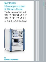
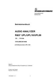
<strong>News</strong> <strong>from</strong> <strong>Rohde</strong> & <strong>Schwarz</strong><br />
DVB-T<br />
High-precision test receiver<br />
Monitoring of<br />
DAB and DVB-T transmitter systems<br />
Airborne VHF/UHF transceivers<br />
Secure voice and data transmission<br />
1999/IV<br />
164
Number 164 1999/IV Volume 39<br />
With digital video broadcasting (DVB) the last<br />
great bastion of analog technology in the field<br />
of consumer electronics industry is about to be<br />
conquered. <strong>Rohde</strong> & <strong>Schwarz</strong> has backed the<br />
right “horse” at a very early stage and is now<br />
able to offer a comprehensive range of<br />
operational and test equipment. For example<br />
the new TV Test Receiver EFA-T, the first test<br />
receiver allowing realtime measurements on<br />
DVB-T signals (page 4). Further articles on<br />
digital TV <strong>from</strong> page 17 onwards<br />
Photo 43 396<br />
Articles<br />
Christoph Balz;<br />
Mathias Leutiger<br />
Michael Fraebel<br />
Peter Wollmann<br />
Erwin Böhler;<br />
Daniel Seemann<br />
DVB-T Test Receiver EFA-T<br />
The test reference: now for terrestrial digital TV too ..................................... 4<br />
Mobile Air Traffic Control Tower MX400<br />
Out in the wilds – air traffic control in no-man's-land ................................... 8<br />
Optical Network Analyzer Q7750 and Optical Chirpform Test Set Q7606<br />
Unique measuring instruments for wavelength division multiplex ................ 11<br />
Communication System Panel TS-CSP<br />
Clear layout instead of cable jungle – flexible wiring of test systems ........... 14<br />
Application notes<br />
Jörg Pfitzner<br />
Harald Weigold<br />
Christoph Balz<br />
Theodor Fokken<br />
Monitoring DAB and DVB-T transmitter systems<br />
Measurements made easy: firm grip on complex problems ........................ 17<br />
MPEG2 measurement generators and decoders<br />
Let's go west: ATSC ready for takeoff ...................................................... 20<br />
TV Test Receiver EFA<br />
A precision instrument that also analyzes arbitrary QAM signals ............... 22<br />
Miniport Receiver EB200: hard times for eavesdroppers ........................... 24<br />
Correction of test hint in issue No. 163:<br />
“Conversion of C/N or SNR to E b /N 0 in DVB” ........................................ 25<br />
2 <strong>News</strong> <strong>from</strong> <strong>Rohde</strong> & <strong>Schwarz</strong> Number 164 (1999/IV)
Panorama<br />
Reinhard Göster<br />
Holger Jauch<br />
Ekkehardt Claußen<br />
EMC test centers of any size – precise, fully automatic and universal ......... 26<br />
3G test scenario in research and development: Third-generation<br />
mobile radio – universal test concepts pave the way ................................ 29<br />
Airborne VHF/UHF Transceivers Series 6000<br />
Software radios – top in secure data and voice transmission ..................... 32<br />
Regular features<br />
Christian Hess<br />
Akihiko Yoshimura<br />
In brief: <strong>Rohde</strong> & <strong>Schwarz</strong> Web site in new look<br />
and more comprehensive than ever ........................................................ 28<br />
In brief: The world’s first portable crystal clock returns<br />
home to <strong>Rohde</strong> & <strong>Schwarz</strong> museum ......................................................... 37<br />
Information in print ............................................................................... 34<br />
Press comments .................................................................................... 35<br />
<strong>News</strong>gram .......................................................................................... 36<br />
Dr Ralph Wernsdorf<br />
Final article: How random is chance? ..................................................... 38<br />
Many renowned companies of the automobile,<br />
consumer electronics and mechanical<br />
engineering industry have for years relied on<br />
EMC test technology <strong>from</strong> <strong>Rohde</strong> & <strong>Schwarz</strong>:<br />
covering everything <strong>from</strong> small EUTs to widebody<br />
aircraft. Recently Audi AG put its new<br />
EMC test center into operation, fully equipped<br />
with <strong>Rohde</strong> & <strong>Schwarz</strong> technology (page 26)<br />
Photo 43 350/5<br />
Imprint<br />
Published by ROHDE & SCHWARZ GmbH & Co. KG · Mühldorfstraße 15 · D-81671 München · Support<br />
Center: Tel. (+49) 01805124242 · E-mail: customersupport@rsd.rsd.de · Fax (+4989) 4129-3777<br />
Editor and Layout: Ludwig Drexl, Redaktion – Technik (German) · English translation: Dep. 5CL4<br />
Photos: Stefan Huber · Circulation 90 000 six times a year · ISSN 0028-9108 · Supply free of charge<br />
through your nearest <strong>Rohde</strong> & <strong>Schwarz</strong> representative · Printed in Germany by peschke druck, München<br />
Reproduction of extracts permitted if source is stated and copy sent to <strong>Rohde</strong> & <strong>Schwarz</strong> München.<br />
<strong>News</strong> <strong>from</strong> <strong>Rohde</strong> & <strong>Schwarz</strong> Number 164 (1999/IV) 3
Articles<br />
DVB-T Test Receiver EFA-T<br />
The test reference:<br />
now for terrestrial digital TV too<br />
After successful startup of the first European DVB-T network (terrestrial digital<br />
video broadcasting) in Britain with currently over 500000 users, DVB-T is gaining<br />
ground in Europe at an ever faster pace. In this context the new DVB-T model of<br />
the EFA family of test receivers [1] meets the demand for high-precision reception<br />
measurements. Compact in design and featuring comprehensive automatic test functionality,<br />
the instrument is ideal in R&D, transmission modulator production and<br />
operative monitoring of TV signals.<br />
Photo 43 310/6<br />
FIG 1 DVB-T Test Receiver EFA-T completes the<br />
universal EFA test receiver family adding measurements<br />
on terrestrial digital TV systems<br />
Universal test receivers for<br />
digital TV<br />
Terrestrial digital TV is being introduced<br />
in the face of competition <strong>from</strong><br />
other, likewise digitally modulated TV<br />
signals transmitted via satellite and<br />
cable. The digital standards reduce<br />
the problems encountered with forerunner<br />
analog transmission, like limited<br />
program variety, degraded signal<br />
quality under adverse reception conditions<br />
or system-inherent shortcomings.<br />
Three major terrestrial digital TV standards<br />
have established themselves to<br />
date. The ATSC standard adopted in<br />
1996 by the Federal Communications<br />
Commission (FCC) is applied in the<br />
United States, Canada, Argentina,<br />
South Korea and Taiwan. ISDB-T, the<br />
Japanese version of the DVB-T standard,<br />
is currently only used in Japan,<br />
where the first countrywide network is<br />
planned for the year 2003.<br />
The most widely used standard, and<br />
thus the one apparently progressing<br />
at the fastest pace, is the DVB-T standard<br />
specified by the European Telecommunications<br />
Standards Institute<br />
(ETSI) in 1997. It has been adopted<br />
in over 19 countries, including the<br />
15 EU member nations, as well as<br />
Australia, New Zealand, India and<br />
Singapore. Following the British lead,<br />
the introduction of digital TV to this<br />
standard is now approaching in<br />
Spain, Sweden and New Zealand.<br />
In the light of competition <strong>from</strong> cable<br />
and satellite and the high expectations<br />
of TV viewers, the requirements made<br />
on the reliability and quality of digital<br />
signals are extremely high. The EFA<br />
test receiver family now comes with a<br />
new model – EFA-T – that covers all<br />
the measurement tasks to be performed<br />
in this scenario.<br />
4 <strong>News</strong> <strong>from</strong> <strong>Rohde</strong> & <strong>Schwarz</strong> Number 164 (1999/IV)
Articles<br />
EFA-T – characteristics<br />
The test receiver, fully compatible in<br />
all its functions with ETS300744,<br />
receives, decodes and analyzes DVB-T<br />
signals. All essential parameters for<br />
demodulation of the receive signal can<br />
be selected automatically or manually:<br />
• Bandwidth 8 MHz, optionally<br />
6 MHz or 7 MHz<br />
• COFDM modulation with 2K or<br />
8K FFT<br />
• QPSK, 16QAM or 64QAM<br />
constellation<br />
• Code rate 1/2, 2/3, 3/4, 5/6,<br />
7/8<br />
• Guard interval 1/4, 1/8, 1/16,<br />
1/32<br />
• Hierarchical demodulation<br />
= = 1, 2, 4<br />
EFA-T – test reference for DVB-T<br />
The newly developed Test Receiver<br />
EFA-T features a multitude of innovative<br />
measurement functions right <strong>from</strong><br />
the basic version, making it a test reference<br />
for the systematic detection and<br />
analysis of failures and disturbances<br />
in the transmission channel (several<br />
international patents pending). Apart<br />
<strong>from</strong> total analysis, for example of bit<br />
error rate (BER), detailed analyses of<br />
freely selectable carrier ranges of the<br />
OFDM signal can be performed. These<br />
include:<br />
• Constellation diagrams<br />
• Calculation of transmission<br />
parameters<br />
• Display of modulation error ratio<br />
(MER) as function of frequency<br />
• Presentation of eye aperture as<br />
function of frequency<br />
Any failures and disturbances already<br />
appear in the display of all carriers of<br />
the OFDM signal. They can then be<br />
accurately localized by narrowing<br />
down the carrier range (see FIGs 3 to<br />
8). A particularly effective method here<br />
is presentation of eye aperture as a<br />
function of frequency (FIG 5). What it<br />
means is that the I and Q values are<br />
shown together with the decision<br />
thresholds, revealing any transmission<br />
errors at a glance and allowing disturbed<br />
carriers to be identified.<br />
Investigations have shown that transmission<br />
errors (BER) are attributable<br />
often to only a few carriers while most<br />
carriers are decoded correctly.<br />
Detailed analysis is possible by means<br />
of constellation diagrams of previously<br />
identified single carriers.<br />
EFA-T – operating principle<br />
(FIG 2)<br />
First the receive signal is conditioned for<br />
the OFDM demodulator. Three slots for filters<br />
of 8 MHz (optionally 6 or 7 MHz)<br />
bandwidth are available in the receive<br />
section for band limiting.<br />
Noise can be superimposed on the receive<br />
signal by a built-in noise generator and<br />
associated attenuator. The C/N ratio is<br />
entered directly thanks to a level meter for<br />
both the wanted and noise signal.<br />
Down-conversion to the second IF is followed<br />
by passive analog lowpass filters,<br />
the signal then passing to an A/D converter<br />
with 12 bit resolution (fixed-frequency sampling<br />
without oscillator tracking).<br />
The digitized signal is then applied to the<br />
synchronization, digital complex mixer, FFT,<br />
channel estimation, error protection and<br />
MPEG2 processing stages.<br />
After channel estimation, the I and Q components<br />
are coupled out for the constellation<br />
diagram and calculation of further<br />
transmission parameters and taken to the<br />
DSP section. This directly drives the display<br />
controller, which results in extremely fast<br />
graphical processing of measured results.<br />
FIG 2<br />
Operating principle of EFA-T<br />
Control bus<br />
Receive<br />
section<br />
Level<br />
meter<br />
AGC 1<br />
SAW<br />
f IF,1 = 36 MHz<br />
8 (7/6) MHz<br />
Noise<br />
generator<br />
LPF<br />
AGC 2<br />
f IF,2<br />
A<br />
D<br />
OFDM<br />
demodulator<br />
DSP:<br />
Constellation<br />
analyzer<br />
Parameter<br />
analyzer<br />
I/Q (f)<br />
MPEG2<br />
measurement<br />
decoder<br />
(optional)<br />
Osc.<br />
f OSC<br />
f CLK<br />
MER (f)<br />
FFT<br />
2/8 K<br />
Channel<br />
estimation<br />
Inner<br />
de-interleaver<br />
Viterbi<br />
decoder<br />
Other<br />
de-interleaver<br />
Synchronization<br />
Reed-<br />
Solomondecoder<br />
Energy<br />
dispersal<br />
MPEG<br />
interface<br />
Display<br />
controller<br />
NCO<br />
FEC<br />
<strong>News</strong> <strong>from</strong> <strong>Rohde</strong> & <strong>Schwarz</strong> Number 164 (1999/IV) 5
Articles<br />
· 3 EFA-T – realtime signal<br />
analysis<br />
EFA-T – the monitoring<br />
receiver<br />
4<br />
The powerful digital signal processing<br />
of EFA-T provides fast and thorough<br />
analysis of the received DVB-T signal.<br />
Analysis is performed simultaneously<br />
with, but quite independently of, demodulation<br />
and decoding. The MPEG<br />
transport stream is permanently available<br />
for decoding as well as for vision<br />
and sound reproduction.<br />
Thanks to this realtime analysis capability,<br />
the high number of measured<br />
values necessary for the complex calculation<br />
and display processes are<br />
made available in an extremely short,<br />
so far unequalled time for subsequent<br />
mathematical/statistical processing.<br />
Because of its high-speed data acquisition,<br />
Test Receiver EFA-T is an ideal<br />
choice not only in R & D but also in<br />
production applications, where short<br />
measurement cycles are called for.<br />
Monitoring receivers permanently monitor<br />
the main parameters of broadcast<br />
signals directly at the transmitting station.<br />
An alarm is triggered if a measured<br />
value is outside a predefined<br />
test interval. Test Receiver EFA-T is tailored<br />
for this application: six parameters<br />
with separately selectable alarm<br />
thresholds can be chosen for monitoring<br />
(FIG 9). Particularly worth emphasizing<br />
is BER monitoring at the various<br />
stages of reception. This allows<br />
emerging problems to be identified<br />
at an early stage.<br />
All errors occurring are saved in EFA-T<br />
together with the date and time in error<br />
reports comprising up to 1000 entries.<br />
In addition, EFA-T triggers an acoustic<br />
alarm for the operating personnel.<br />
5<br />
6<br />
EFA-T – mobile or stationary<br />
To meet different requirements in the<br />
transmission of DVB-T signals, the<br />
OFDM demodulator can be optimized<br />
for mobile as well as stationary reception<br />
simply at a keystroke. The resulting<br />
settings mainly affect the speed<br />
and channel equalization process as<br />
well as internal level control. Reception<br />
is thus possible even under highly<br />
adverse conditions.<br />
The bandwidths of the main internal<br />
phase control circuits can also be configured,<br />
for example to analyze noisy<br />
signals (eg phase noise) or signals<br />
exhibiting particularly strong jitter.<br />
Captions for FIG 3 to 10<br />
FIG 3 Measurement menu: all important<br />
data and DVB-T configuration visible at<br />
a glance<br />
FIG 4 Constellation diagram, here with<br />
simultaneous display of 100 OFDM symbols<br />
FIG 5 Complete analysis of transmission<br />
channel showing I/Q as function of<br />
frequency. Disturbance at carrier frequency<br />
1300 is clearly discernible<br />
FIG 6 Display of transmission channel<br />
(same signal as FIG 5). Disturbed carrier is<br />
identified as number 1299<br />
FIG 7 Display of MER as function of<br />
frequency (same signal as FIG 5). Here too,<br />
disturbance at carrier frequency 1300 is<br />
clearly discernible<br />
FIG 8 Constellation diagram for detailed<br />
analysis of disturbed carrier (scattered pilot).<br />
Diagram shows that it is narrowband<br />
interference<br />
FIG 9 Ideal for monitoring tasks: simultaneous<br />
monitoring of six key parameters<br />
FIG 10 Parameter calculation for 2K FFT.<br />
Here detailed analysis of central carrier<br />
(number 852 of transmitted OFDM spectrum)<br />
6 <strong>News</strong> <strong>from</strong> <strong>Rohde</strong> & <strong>Schwarz</strong> Number 164 (1999/IV)
Articles<br />
EFA – the analog and digital<br />
family<br />
Although digital TV will constantly gain<br />
in importance, analog TV will continue<br />
to be used on a very large scale for a<br />
long transition period. This is due to the<br />
limited available frequency resources<br />
and the enormous number of analog<br />
TV sets in circulation since colour TV was<br />
introduced. So TV signals with analog<br />
and digital modulation will coexist in<br />
the same frequency band.<br />
Further options like MPEG2 Decoder<br />
EFA-B4 enhance test receiver functionality<br />
to produce a compact and universal<br />
all-in-one instrument for measuring<br />
digital and analog TV signals.<br />
Mathias Leutiger; Christoph Balz<br />
7<br />
This fact is taken into account in the<br />
EFA test receiver family. An analog<br />
receiver can be fitted with DVB-T<br />
option EFA-B10 to yield a combined<br />
instrument for measurement of analog<br />
and digital terrestrial TV signals. Here<br />
the modular and future-oriented concept<br />
of the EFA test receiver family<br />
again proves its value.<br />
REFERENCES<br />
[1] Christoph Balz; Ernst Polz; Walter Fischer:<br />
TV Test Receiver Family EFA – Top fit for<br />
digital television. <strong>News</strong> <strong>from</strong> <strong>Rohde</strong> &<br />
<strong>Schwarz</strong> (1996) No. 152, pp 17–19<br />
8<br />
9<br />
Condensed data of DVB-T Test Receiver EFA-T<br />
Frequency range<br />
45 MHz to 1000 MHz<br />
5 MHz to 1000 MHz<br />
with optional RF Preselection (EFA-B3)<br />
Input level range<br />
–47 dBm to +14 dBm<br />
–84 dBm to +14 dBm (low-noise)<br />
with optional RF Preselection (EFA-B3)<br />
Bandwidth<br />
6/7/8 MHz<br />
FFT mode<br />
2 K and 8 K<br />
Modulation<br />
QPSK, 16QAM, 64QAM<br />
Guard interval 1/4, 1/8, 1/16, 1/32<br />
Inner code rate 1/2, 2/3, 3/4, 5/6, 7/8<br />
BER analysis<br />
before Viterbi, before and<br />
after Reed-Solomon<br />
Measurement functions<br />
level, BER, MER, carrier suppression,<br />
quadrature error, phase jitter,<br />
amplitude imbalance<br />
Graphical displays<br />
constellation diagram, MER (f), I/Q (f),<br />
further graphics in preparation<br />
(eg spectral analysis)<br />
Output signals<br />
MPEG2-TS: ASI, SPI<br />
Options<br />
MPEG2 Decoder (EFA-B4),<br />
RF Preselection (EFA-B3)<br />
10<br />
Reader service card 164/01<br />
<strong>News</strong> <strong>from</strong> <strong>Rohde</strong> & <strong>Schwarz</strong> Number 164 (1999/IV) 7
Fachbeitrag Articles<br />
Mobile Air Traffic Control Tower MX400<br />
Out in the wilds – air traffic control<br />
in no-man's-land<br />
Mobile Air Traffic Control Tower MX400 (FIG 1) <strong>from</strong> <strong>Rohde</strong> & <strong>Schwarz</strong> was designed<br />
for versatility. It is used worldwide wherever reliable air traffic has to be taken up<br />
within a minimum of time and the necessary infrastructure is lacking. It has been<br />
tried and tested on many occasions under the most adverse conditions and is being<br />
used by international customers, among them the peacekeeping forces in Kosovo.<br />
Ready to go – even in<br />
no-man's-land<br />
MX 400 ensures smooth operation in<br />
almost any region of the world. It can<br />
stand in for a stationary tower, for instance,<br />
if the latter is still under construction<br />
or shut down for modification<br />
or maintenance. It does not make<br />
any difference whether civil or military<br />
installations are concerned. Effective<br />
thermal insulation of the cabin and a<br />
powerful split air-conditioning system<br />
provide optimum working conditions<br />
for staff and reliable system operation<br />
even under the most severe climatic<br />
conditions. Since infrastructure at the<br />
MATC tower site is mostly insufficient<br />
or not available at all, the system works<br />
on a separate Diesel generator and<br />
uninterruptible power supply.<br />
MX400 is suitable for a whole variety<br />
of applications:<br />
• Standby system for main ATC<br />
tower<br />
• Visual control room for airfields/<br />
training center<br />
• Semi-permanent system for<br />
airfields with seasonal air traffic<br />
• Mobile system for search and<br />
rescue operations<br />
• Operations center for air defense<br />
FIG 1 MX400 is set up in a minimum of time<br />
and usable at any site thanks to powerful airconditioning<br />
and autonomous power supply<br />
Photo Werk Köln<br />
8 <strong>News</strong> <strong>from</strong> <strong>Rohde</strong> & <strong>Schwarz</strong> Number 164 (1999/IV)
Articles<br />
Modular, customized concept<br />
Trailer and power supply<br />
MX400 is of modular design, configured<br />
in close cooperation with the customer<br />
and tailored to his needs<br />
(FIG 2). It is made up of<br />
• a trailer with integrated hydraulic<br />
platform and detachable cabin<br />
and<br />
• a separate Diesel generator on a<br />
single-axle trailer (FIG 3).<br />
A scissor-lift hydraulic system elevates<br />
the cabin to the required operational<br />
height of 6.5 m (or to levels in between).<br />
The cabin is designed as an<br />
independent subsystem meeting all<br />
operational requirements of a mobile<br />
system (FIG 5) and complies with the<br />
standards of ATC authorities and the<br />
ICAO (International Civil Aviation<br />
Organization).<br />
FIG 2<br />
Up to three control<br />
positions allow full<br />
access to radiocommunication<br />
equipment, voice<br />
switching system<br />
and meteorological<br />
data<br />
Sensors<br />
Distributor<br />
Diesel<br />
generator<br />
HF, VHF and UHF radiocommunication<br />
The proven transceivers of the 200/<br />
400U series <strong>from</strong> <strong>Rohde</strong> & <strong>Schwarz</strong><br />
are used for communication in the VHF<br />
Vertical, stacked antennas<br />
VHF-UHF radiocommunication system<br />
Voice<br />
recording<br />
External interfaces<br />
Voice<br />
switching<br />
Airconditioning<br />
and UHF bands. HF transceivers and<br />
a VHF-UHF direction finder are optional.<br />
Controllers are integrated for operation<br />
of the entire radio equipment.<br />
Global use and highly mobile<br />
MX400 is set up and put into operation<br />
in a minimum of time. Two persons<br />
will need approximately one hour.<br />
The tower is easily transported, so<br />
changing the site is just as fast. Cabin<br />
dimensions (20" standard size) are in<br />
line with DIN and ISO regulations<br />
and standards. This simplifies international<br />
transportation:<br />
… by land<br />
• The complete system can be<br />
attached to a vehicle, eg Unimog,<br />
with the generator coupled to the<br />
trailer or<br />
• piggybacked on a truck<br />
… by sea<br />
• Transport in a ship as the top<br />
container<br />
… and by air<br />
• Transport in a plane, eg Hercules<br />
C-130 or Ilyushin (FIG 4)<br />
• or by helicopter<br />
FIG 4 Loading MATC in Ilyushin IL-76 transport<br />
plane<br />
FIG 3 Trailer and generator: compact and<br />
designed for international transportation<br />
Photo Werk Köln<br />
Photo Werk Köln<br />
<strong>News</strong> <strong>from</strong> <strong>Rohde</strong> & <strong>Schwarz</strong> Number 164 (1999/IV) 9
Articles<br />
Highly selective, automatic filters prevent<br />
collocation problems and ensure<br />
undisturbed radio operation. Up to<br />
four vertical, stacked antennas make<br />
setting up of additional antenna masts<br />
in the field unnecessary.<br />
Voice switching system<br />
The voice switching system assumes<br />
the function of a telephone exchange.<br />
It allows access to any transceiver via<br />
selection panels.<br />
Voice recording<br />
Using a digital recorder, all calls <strong>from</strong><br />
the voice switching system can be<br />
stored on a hard disk or magnetooptical<br />
storage medium that can be<br />
extensively accessed via the application<br />
software.<br />
Meteorological equipment<br />
Sensors are fixed to an external mast<br />
on the roof of the control tower cabin.<br />
ATC-relevant data are displayed and<br />
evaluated at the control positions.<br />
Diesel generator<br />
The separate generator provides sufficient<br />
power for autonomous system<br />
operation over several days.<br />
Safety packet<br />
This comprises signal lights, optical<br />
observation and signalling equipment,<br />
crash alarm, fire extinguishing system,<br />
etc.<br />
The system equipment shows: nothing<br />
has been forgotten. MATC can assume<br />
operation at any site quickly and<br />
reliably.<br />
Michael Fraebel<br />
Reader service card 164/02<br />
FIG 5<br />
Control tower cabin with three<br />
ATC workstations<br />
Photo 40 738/3<br />
FIG 6<br />
VHF-UHF transceivers <strong>from</strong> <strong>Rohde</strong> & <strong>Schwarz</strong><br />
used for radiocommunication<br />
Photo 41 960<br />
10 <strong>News</strong> <strong>from</strong> <strong>Rohde</strong> & <strong>Schwarz</strong> Number 164 (1999/IV)
Articles<br />
Optical Network Analyzer Q7750 and<br />
Optical Chirpform Test Set Q7606<br />
Unique measuring instruments for<br />
wavelength division multiplex<br />
The enormous amount of data distributed today around the globe is mostly transmitted<br />
via fiber-optic cables, submarine cables featuring largely in this [1]. An<br />
efficient way of increasing the data rate in fiber-optic cable networks is to transmit<br />
several optical wavelengths using the wavelength division multiplex method.<br />
ADVANTEST, a cooperating partner of <strong>Rohde</strong> & <strong>Schwarz</strong> for many years, has<br />
launched two completely new and unique instruments on the world market for<br />
measurements on active and passive components in this application.<br />
Photo: Photodisk<br />
Before:<br />
one fiber, one wavelength<br />
The developers of the first fiberglass<br />
transmission links knew that their bandwidth<br />
resources were immensely<br />
greater than those of copper cables.<br />
But many years of intensive research<br />
were required before this potential<br />
could be adequately utilized.<br />
Until about three years ago, information<br />
in fiber-optic cables was transmitted<br />
to relatively wideband receivers<br />
almost exclusively with a single wavelength.<br />
More than ten years ago<br />
already, engineers achieved data<br />
rates of 2.5 Gbit/s with this method<br />
in the laboratory, shortly after<br />
10 Gbit/s and more. Since these transmission<br />
rates are now far too low for<br />
FIG 1<br />
Users familiar with<br />
RF network analysis<br />
will immediately feel<br />
at ease with Optical<br />
Network Analyzer<br />
Q7750: only the<br />
enter key labelled<br />
“THz” may seem<br />
unusual at first<br />
Photo 43 308<br />
<strong>News</strong> <strong>from</strong> <strong>Rohde</strong> & <strong>Schwarz</strong> Number 164 (1999/IV) 11
Articles<br />
handling international information<br />
exchange, eg on the Internet, new<br />
ways were sought of making full use<br />
of the bandwidth capacity of glass<br />
fibers.<br />
Now:<br />
one fiber, many wavelengths<br />
Since a data rate increase at the transmitter<br />
end can presently only be<br />
achieved with considerable technical<br />
outlay, the use of several multiplexed<br />
optical wavelengths is an efficient<br />
alternative. It is possible, for instance,<br />
to transmit 20 Gbit/s using eight of<br />
the presently favourably priced<br />
2.5 Gbit channels on a single fiber<br />
with the aid of WDM (wavelength<br />
division multiplex). With greater channel<br />
density of up to 128 x 10 Gbit/s,<br />
laboratories are about to achieve<br />
transmission rates in the terabit range<br />
(DWDM = dense wavelength division<br />
multiplex).<br />
In the high-frequency range the step<br />
into multiplexing was taken decades<br />
ago. With optical transmissions this<br />
was not possible for a long time since,<br />
until a few years ago, really stable<br />
transmitters were not available. In the<br />
beginning, the developers made do<br />
with two widely spaced wavelengths,<br />
but this proved to be unsuitable for<br />
long-haul transmissions. All modern<br />
WDM and DWDM systems operate<br />
in the region of 1550 nm with a channel<br />
spacing of often only 100 GHz<br />
(0.8 nm) and soon even 50 GHz<br />
(0.4 nm).<br />
Compared to the standards used in<br />
radiocommunication, this spacing<br />
strikes one as being very wide. The<br />
situation is completely different in the<br />
case of optical transmissions. Here<br />
extremely stable lasers and highly<br />
selective wavelength demultiplexers<br />
are required, which also makes high<br />
demands on measuring instruments.<br />
ADVANTEST took up the challenge<br />
and extended its range of measuring<br />
instruments accordingly, presenting<br />
two new instruments that are absolutely<br />
unique on the world market.<br />
Unrivalled instruments for<br />
measurements on active and<br />
passive components<br />
Optical Network Analyzer Q7750<br />
(FIG 1) is designed for characterizing<br />
passive elements, eg optical wavelength<br />
splitters, which split up the<br />
WDM signal into single channels before<br />
it can be detected by a receiver.<br />
Anyone familiar with RF network analysis<br />
will quickly feel at ease with this<br />
instrument. Only the enter key labelled<br />
“THz” (1 THz = 1000 GHz) indicates<br />
that Q7750 measures in the region<br />
of infrared light. It simultaneously<br />
measures reflection and transmission<br />
characteristics, the display being<br />
switchable between amplitude, optical<br />
group delay and chromatic dispersion.<br />
Revolutionary are not only the<br />
type and scope of result recording but<br />
also the short measurement time of only<br />
several seconds depending on instrument<br />
settings.<br />
Optical Chirp Test Set Q7606 (FIG 2)<br />
is used for characterizing active com-<br />
FIG 2 Optical Chirp Test Set Q7606 measures<br />
wavelength stability during level transition with<br />
unrivalled time-domain and spectral resolution<br />
Photo 43 307<br />
12 <strong>News</strong> <strong>from</strong> <strong>Rohde</strong> & <strong>Schwarz</strong> Number 164 (1999/IV)
Articles<br />
ponents, ie laser generators and modulators.<br />
It measures wavelength stability<br />
during level transitions with unrivalled<br />
resolution in the time domain<br />
and spectrum. Q7606 works by the<br />
principle of an optical heterodyning<br />
receiver and its 20 MHz frequency<br />
resolution in the spectral range is<br />
higher by several powers of tens than<br />
that of an optical spectrum analyzer.<br />
This instrument opens up completely<br />
new potential in the fairly young field<br />
of optical phase modulation, unrivalled<br />
by any other product on the market.<br />
FIG 3 shows amplitude (blue) and<br />
optical frequency modulation (chirp)<br />
characteristics for comparison.<br />
By offering these new measuring<br />
instruments, <strong>Rohde</strong> & <strong>Schwarz</strong> will contribute<br />
its share to reducing the time<br />
for measuring important parameters<br />
of WDM components in development,<br />
production and quality assurance.<br />
Users will be able to advance the<br />
development of even more powerful<br />
transmission components for the information<br />
society of the future.<br />
Peter Wollmann<br />
Condensed data of Q7750<br />
Wavelength<br />
Channels<br />
Measurement functions<br />
Wavelength error<br />
Sweep range<br />
Dynamic range<br />
Group delay<br />
Chromatic dispersion<br />
Condensed data of Q7606<br />
Wavelength<br />
Power range<br />
Free spectral range<br />
Demodulation bandwidth<br />
Resolution of resolution bandwidth<br />
Insertion loss<br />
Reader service card 164/03<br />
REFERENCES<br />
[1] Peter Wollmann: Global players under the<br />
sea: market leader for fault location in submarine<br />
cables. <strong>News</strong> <strong>from</strong> <strong>Rohde</strong> & <strong>Schwarz</strong><br />
(1999) No. 163, pp 42–43<br />
1530 nm to 1600 nm<br />
S11 and S21 (optical)<br />
amplitude, group delay,<br />
chromatic dispersion<br />
0.025 nm<br />
0.1 nm to 70 nm<br />
transmission: 35 dB (typ. 40 dB)<br />
reflection: 33 dB (typ. 38 dB)<br />
0.1 ps to 25 ns<br />
0.01 ps/nm to 1 µs/nm<br />
1510 nm to 1590 nm (Q7606B)<br />
1530 nm to 1580 nm (Q7606A)<br />
–20 dBm to +10 dBm (Q7606B)<br />
–10 dBm to +10 dBm (Q7606A)<br />
150 GHz 15 GHz<br />
100 Hz to 50 GHz<br />
20 MHz pp<br />
10 dB (Q7606B only)<br />
FIG 3<br />
Amplitude (blue) and optical frequency<br />
modulation (red)<br />
<strong>News</strong> <strong>from</strong> <strong>Rohde</strong> & <strong>Schwarz</strong> Number 164 (1999/IV) 13
Articles<br />
Communication System Panel TS-CSP<br />
Clear layout instead of cable jungle –<br />
flexible wiring of test systems<br />
Automatic test systems for functional tests and final testing of electronic products<br />
require a large variety of DUT fixtures, stimulus signals, etc. Soon there is a tangle of<br />
connecting cables and it gets even worse if something has to be changed. Communication<br />
System Panel TS-CSP with its switch matrix modules is the solution to this<br />
problem. It was specially designed for use in production test systems and establishes<br />
any kind of connection between DUT and measuring instruments efficiently and costeffectively.<br />
Convenient software makes it easy for the user to have everything under<br />
control and to make changes quickly and error-free.<br />
Efficient and versatile for<br />
modern production environments<br />
Instead of a chaotic tangle of cables<br />
as can often be found between DUT<br />
fixture, measuring instruments, relay<br />
boxes or data acquisition cards and<br />
power supplies, Communication<br />
System Panel TS-CSP (FIG1) provides<br />
a cost-effective alternative that is<br />
especially appreciated in modern production<br />
environments. All DUT signals<br />
are distributed via switch matrix modules<br />
that can be conveniently interconnected<br />
via software as required.<br />
In a conventional configuration several<br />
signal sources and measuring instruments<br />
are often connected with a multitude<br />
of cables via various plug-in<br />
adapters or with the aid of expensive<br />
pylon connections. Not so with TS-CSP.<br />
The panel significantly cuts time and<br />
costs incurred in the configuration,<br />
maintenance and modification of test<br />
systems. Signals are combined in<br />
groups and then distributed in the<br />
FIG 1<br />
Communication System Panel TS-CSP –<br />
switching center for test systems (here in<br />
conjunction with Digital Radiocommunication<br />
Tester CMD65 for testing mobile phones)<br />
14 <strong>News</strong> <strong>from</strong> <strong>Rohde</strong> & <strong>Schwarz</strong> Number 164 (1999/IV)
Articles<br />
There are many applications …<br />
Communication System Panel TS-CSP<br />
is ideal for use in:<br />
• Functional test systems for<br />
telecommunication products such<br />
as mobile phones, cordless<br />
terminal equipment and associated<br />
base stations<br />
• Production testers for products<br />
<strong>from</strong> automation, sensor technology<br />
and telemetry sectors<br />
• Automotive test systems<br />
• EMC/EMI test systems as RF<br />
switch matrix<br />
• Lab test sets<br />
FIG 2 User interface for interactive access to<br />
all device functions<br />
TS-CSP. The optimization of the panel<br />
for use in production systems and the<br />
integrated switching technique result<br />
in an extremely favourable price/performance<br />
ratio per test channel.<br />
Compact integration of basic<br />
functions into modular concept<br />
RF testpoints with signals in the frequency<br />
range <strong>from</strong> DC to 12 GHz can<br />
be set on the measuring devices under<br />
software control.<br />
What is more, node potentials, operating<br />
voltages and audio signals that<br />
have to be checked as part of functional<br />
tests can also be switched automatically<br />
via the Universal Switch<br />
Matrix TS-USM.<br />
Measurement functions for analog voltages<br />
as well as digital signal acquisition<br />
are already implemented in<br />
TS-USM. A programmable voltage<br />
source for analog output levels and<br />
digital output ports for DUT stimula-<br />
Two types of cabinets are available to<br />
accommodate either two or five switch<br />
matrix modules. This means that efficient<br />
solutions can be implemented<br />
even for small production test systems.<br />
The following switch matrix modules<br />
are available:<br />
• TS-USM<br />
Universal Switch Matrix: offering<br />
multi I/O functionality<br />
• TS-RFM<br />
RF Switch Matrix: for RF signal<br />
switching<br />
• TS-USMF<br />
Universal Switch Matrix Fixture:<br />
rugged fixture interface for use in<br />
production tests<br />
Two different RF Switch Matrix Modules<br />
TS-RFM with four or twelve relays<br />
are available for efficient RF signal<br />
distribution. The required number of<br />
FIG 3<br />
Clear layout instead<br />
of cable jungle: neat<br />
graphical user<br />
interface for switch<br />
matrix relays<br />
<strong>News</strong> <strong>from</strong> <strong>Rohde</strong> & <strong>Schwarz</strong> Number 164 (1999/IV) 15
Articles<br />
tion are also integrated. DUT powering<br />
<strong>from</strong> an external supply unit is<br />
switched by power relays in TS-USM.<br />
To control the switch matrix modules<br />
an IEC/IEEE bus interface is provided<br />
as standard. A high-speed TTL<br />
interface is optionally available in the<br />
form of PC Card Interface PS-B11.<br />
Simultaneous testing through<br />
cascading<br />
Simultaneous testing of several DUTs<br />
is made possible by flexible scaling<br />
and the large number of channels provided<br />
by TS-CSP. Fitted with a remotecontrol<br />
interface, TS-USM can be used<br />
as a baseboard for cascading further<br />
switch matrix modules. In this way highperformance<br />
systems can then be configured<br />
to contain, for instance, the<br />
complete signal switching of a functional<br />
tester for mobile phones that is<br />
able to simultaneously test a panel of<br />
four PCBs.<br />
Straightforward cabling for<br />
complex test systems<br />
The DUT fixture can be connected<br />
directly, ie mechanically docked, to<br />
Universal Switch Matrix TS-USM with<br />
the aid of two 160-pin connectors.<br />
Often, however, the DUT fixture is<br />
located remotely in an automated contacting<br />
station within a production line.<br />
In this case the Universal Switch Matrix<br />
Fixture TS-USMF can be used to connect<br />
the DUT fixture to the TS-CSP<br />
panel. The test and supply signal lines<br />
are combined in DUT-specific groups<br />
and rearranged so that they can be<br />
adapted with the aid of lockable edge<br />
connectors. This significantly cuts the<br />
time required to service and maintain<br />
the tester and adapt the DUT fixture.<br />
The RF cable connections to the measuring<br />
instruments are made via<br />
N connectors. SMA connectors, preferred<br />
for test fixtures, are provided<br />
to take the signals <strong>from</strong> the DUT to RF<br />
Switch Matrix TS-RFM.<br />
Comprehensive software support<br />
ensured<br />
<strong>Rohde</strong> & <strong>Schwarz</strong> provides comprehensive<br />
driver support for C programming<br />
language under LabWindows/CVI.<br />
The driver software conforms to the<br />
international VISA (virtual instrument<br />
standard architecture) standard drawn<br />
up to provide standardized software<br />
modules for more efficient test program<br />
generation. TS-CSP of course features<br />
the hardware and software selftest<br />
functions that are required for use in<br />
production environments.<br />
Based on this driver software, an<br />
operating program is available for the<br />
communication system panel (FIG 2)<br />
that allows the user to control the panel<br />
simply by mouse clicks. This reduces<br />
familiarization time to a minimum. As<br />
the relay matrix modules too can be<br />
controlled <strong>from</strong> the graphical user interface<br />
(FIG 3), the test engineer can<br />
put fixture wiring into operation and<br />
test it interactively.<br />
Erwin Böhler; Daniel Seemann<br />
Condensed data of TS-CSP, TS-USM, TS-RFM<br />
TS-CSP Slots 2 or 5 (cabinet height of 2 HU or 4 HU)<br />
Remote-control interface IEC/IEEE bus or direct TTL with PS-B11<br />
TS-USM Digital inputs/outputs 40<br />
Optocouplers<br />
8 inputs, 8 outputs, 5 V/24 V<br />
Open-collector drivers 16<br />
A/D converter<br />
8 channels/12 bits, 2 channels/16 bits<br />
D/A converter<br />
1 channel, 16 bits, 5 V/10 V<br />
AF matrix<br />
analog switch, relay matrix<br />
single relays, power relays<br />
TS-RFM TS-RFM1 12 RF relays, DC to 12 GHz<br />
TS-RFM3<br />
4 RF relays, DC to 12 GHz<br />
Reader service card 164/04<br />
16 <strong>News</strong> <strong>from</strong> <strong>Rohde</strong> & <strong>Schwarz</strong> Number 164 (1999/IV)
Application notes<br />
Photo 43 172/2<br />
Monitoring DAB and DVB-T transmitter systems<br />
Measurements made easy:<br />
firm grip on complex problems<br />
To identify transmitters, handle interference and verify compliance with stipulated<br />
conditions for authorization, the monitoring services of licensing authorities must<br />
be capable of measuring the technical parameters of transmitter systems off air.<br />
<strong>Rohde</strong> & <strong>Schwarz</strong> offers an extensive range of monitoring and measuring equipment<br />
for this purpose (FIG 1).<br />
FIG 1 <strong>Rohde</strong> & <strong>Schwarz</strong> offers an extensive<br />
range of stationary and mobile monitoring and<br />
measuring equipment for the latest methods of<br />
digital transmission<br />
Evaluation of interference on digital<br />
transmission links additionally requires<br />
measurements of coverage and bit<br />
error rate. Here too, <strong>Rohde</strong> & <strong>Schwarz</strong><br />
is able to offer a wide selection of coverage<br />
measurement systems [2].<br />
Typical tasks of monitoring<br />
services<br />
Receive level<br />
The strength of the receive level must<br />
be known to assess quality and propagation<br />
conditions. And it is also the<br />
basis for coverage measurements.<br />
Unlike with analog signals, the type<br />
of detector used plays an important<br />
role in transmissions with digital contents.<br />
Depending on the modulation<br />
of the individual carriers, the level of<br />
a DAB/DVB-T signal has different<br />
peak, average and rms values.<br />
Whereas the peak value of the main<br />
carrier (or the sum of the carriers with<br />
COFDM) represents the maximum of<br />
the rms values collected during the<br />
measurement time, the time-averaged<br />
rms value corresponds to the power<br />
of an unmodulated CW carrier of the<br />
same level. Both values can be varied<br />
by suitably influencing (coding) the<br />
transmitted information. For example,<br />
if you ensure that practically no<br />
64QAM values simultaneously have 0°<br />
or 180° phase and maximum amplitude,<br />
the result is a signal with a very<br />
large margin between peak and rms,<br />
whereas in simple frequency shift key-<br />
Complete product line for<br />
complex measurement tasks<br />
Modern DAB and DVB-T systems use<br />
complex modes of digital transmission,<br />
the measurement and identification of<br />
which require special instruments and<br />
methods. All major technical parameters<br />
of such systems can be measured<br />
with Spectrum Monitoring System<br />
ARGUS-IT (formerly SMSI) [1] together<br />
with Spectrum Analyzer FSE, Signal<br />
Analyzer FSIQ or EMI Test Receiver<br />
ESI plus Measurement Software<br />
ArgusMon (FIG 2). Some typical measurements<br />
are described below.<br />
FIG 2<br />
Dialog window of EMI Test Receiver ESI in<br />
DAB/DVB-T measurements with Measurement<br />
Software ArgusMon<br />
<strong>News</strong> <strong>from</strong> <strong>Rohde</strong> & <strong>Schwarz</strong> Number 164 (1999/IV) 17
Application notes<br />
ing without any amplitude modification<br />
the two values will be the same.<br />
For adequate reception quality, the<br />
total energy applied to the receiver,<br />
ie the rms value, is decisive. If the digital<br />
transmission system is the source<br />
of interference however, the peak value<br />
is the key factor, since this determines<br />
the extent of interference especially on<br />
analog receivers. So monitoring services<br />
must be capable of measuring<br />
both peak and rms values. The difference<br />
between the two is called the crest<br />
factor and specified in dB. It is a characteristic<br />
feature of every kind of digital<br />
transmission, and for DAB/DVB-T<br />
it is typically between 10 dB and<br />
13 dB. To avoid impairment of other<br />
radio services by high peak loads and<br />
to make effective use of available transmitter<br />
power, it is necessary to keep<br />
this value as low as possible, for example<br />
by appropriate coding of the<br />
data stream.<br />
Digital transmission systems take up a<br />
lot of bandwidth, so broader IF filters<br />
than for analog radio services are<br />
usually needed to measure level<br />
accurately. Assuming that the transmitted<br />
energy is uniformly distributed<br />
across the used channel (as with DAB<br />
and DVB-T), the entire level can also<br />
be measured with narrower filters and<br />
converted to the actual bandwidth. The<br />
ArgusMon software sets the analyzer<br />
to a filter bandwidth of 1 MHz for this<br />
measurement. Conversion to entire<br />
level is done automatically using the<br />
occupied bandwidth measured narrowband.<br />
for analog signals. The decisive parameter<br />
in most cases is the 99%<br />
bandwidth, ie the bandwidth into<br />
which 99% of the total emitted energy<br />
falls. The DAB/DVB-T signal is<br />
scanned for this purpose using a 1 kHz<br />
test filter. Calculation of the 99% bandwidth<br />
is then made by graphical integration<br />
of the recorded RF spectrum.<br />
Two markers are set on the cutoff frequencies<br />
for a plausibility check by<br />
the user.<br />
Frequency<br />
The frequency of DAB/DVB-T signals<br />
cannot be measured like with analog<br />
signals because of the special nature<br />
of the modulation. Measurement Software<br />
ArgusMon calculates the<br />
frequency using the two marker frequencies<br />
of the bandwidth measurement<br />
and displays it.<br />
Vestigial sideband characteristic<br />
Measuring the characteristic of vestigial<br />
sideband emissions is of particular<br />
importance with DAB/DVB-T transmitters.<br />
FIG 3<br />
DAB transmitter<br />
masks according to<br />
Wiesbaden<br />
agreement<br />
Relative level<br />
(referred to<br />
4 kHz filter)<br />
Due to the almost rectangular form of<br />
the RF spectrum of DAB/DVB-T transmitters,<br />
practically the full transmitting<br />
energy is present directly at the boundary<br />
to channels of adjacent radio services<br />
– unlike with all other systems.<br />
The specified transmitter mask, defining<br />
spectral characteristic versus frequency,<br />
has very steep edges at the<br />
channel boundaries to prevent undue<br />
impairment of other radio services by<br />
vestigial sideband emissions. Compliance<br />
with these masks is especially<br />
difficult in the case of DAB/DVB-T<br />
transmitters since the type of signal<br />
involved, with its large number of adjacent<br />
carriers, is susceptible to the<br />
formation of intermodulation products.<br />
Reducing vestigial sideband emissions<br />
to an acceptable level can in most<br />
cases be achieved only by considerable<br />
technical effort at the transmitter<br />
end. Monitoring services as well as<br />
the operators of such transmitters must<br />
therefore be able to measure the characteristic<br />
of sideband emissions. The<br />
currently valid transmitter masks for<br />
DAB and DVB-T (FIG 3/4) stipulate<br />
DAB transmitter masks<br />
–30 dB<br />
–50 dB<br />
–70 dB<br />
–90 dB<br />
–130 dB<br />
–110 dB<br />
critical cases<br />
non-critical cases<br />
–4 MHz –3 MHz –2 MHz –1 MHz 0 MHz 1 MHz 2 MHz 3 MHz 4 MHz<br />
Frequency offset<br />
Occupied bandwidth<br />
This is an important criterion for identifying<br />
radio services since their channel<br />
spacings are known. And measuring<br />
the occupied bandwidth of digital<br />
systems is especially important because<br />
they often tend to produce considerable<br />
spurious emissions due to the<br />
types of modulation used, and these<br />
unduly expand the actual occupied<br />
bandwidth. Basically bandwidth is<br />
measured by the same principles as<br />
FIG 4<br />
DVB transmitter mask<br />
according to Chester<br />
agreement 1997<br />
Relative level<br />
(referred to 4 kHz filter)<br />
DVB transmitter mask for 8 MHz systems<br />
–30 dB<br />
–50 dB<br />
–70 dB<br />
–90 dB<br />
–110 dB<br />
–130 dB<br />
–12 MHz –7 MHz –2 MHz 3 MHz 8 MHz<br />
Frequency offset<br />
18 <strong>News</strong> <strong>from</strong> <strong>Rohde</strong> & <strong>Schwarz</strong> Number 164 (1999/IV)
Application notes<br />
level reductions down to –126 dB<br />
(referred to entire level and 4 kHz<br />
measurement bandwidth).<br />
From FIG 3 it can be seen that the<br />
spectral characteristic of a DAB transmitter<br />
would have to be recorded with<br />
a dynamic range of at least 110 dB<br />
to verify compliance with the critical<br />
mask. This is not possible with currently<br />
available test receivers or analyzers<br />
alone. The limits of measurement techniques<br />
also show for DVB-T. In the presence<br />
of a multicarrier signal, test<br />
receivers too are susceptible to intermodulation,<br />
so the maximum used level<br />
must not exceed about 50 dBµV for<br />
this measurement (provided that a<br />
measurement filter with 4 kHz bandwidth<br />
is available). With this useful<br />
level, emissions of –27 dBµV would<br />
have to be measured accurately at a<br />
frequency offset of 12 MHz <strong>from</strong> the<br />
DVB-T center.<br />
To measure the vestigial sideband<br />
characteristic of DAB and DVB-T transmitters,<br />
the signal is fed through a<br />
notch filter, which rejects the used<br />
channel as effectively as possible while<br />
letting the adjacent channel pass. In<br />
this way the test receiver is protected<br />
against overloading by the strong used<br />
signal while maintaining its full sensitivity<br />
in the range of interest of vestigial<br />
sideband emissions. The notch filter<br />
must be tunable. The attenuation<br />
along the frequency band to be represented<br />
must be added to the measured<br />
signal to obtain the true, unfiltered<br />
signal. The tracking generator<br />
of the analyzer is needed to accurately<br />
determine the filter response curve.<br />
FIG 5 illustrates the test setup. The<br />
example in the box right demonstrates<br />
how easy such measurements can be.<br />
Summary<br />
The combination of Spectrum Monitoring<br />
System ARGUS-IT with instruments<br />
FSE, FSIQ or ESI makes it very easy to<br />
carry out all the above measurements<br />
on DAB/DVB-T signals required for<br />
interference handling and evaluation<br />
of the RF signal characteristic.<br />
Jörg Pfitzner<br />
Measurements made easy with<br />
ArgusMon software<br />
Vestigial sideband emissions of DVB transmitter<br />
above used channel (FIG 6)<br />
First the notch filter is manually tuned so<br />
that the passband begins at the cutoff frequency<br />
to be represented (depending on<br />
the edge to be measured). A tunable highpass<br />
or lowpass filter or a bandpass filter<br />
may also be used.<br />
The only values you have to enter in the<br />
ArgusMon software are those for the frequency<br />
band to be displayed (682 MHz<br />
to 692 MHz). The program automatically<br />
takes the other values like center frequency<br />
(680 MHz) and bandwidth (7.61 MHz)<br />
<strong>from</strong> the results of measurement in the used<br />
channel.<br />
Once the measurement is started, everything<br />
else is automatic. First the filter response<br />
curve, then the level characteristic of the<br />
filtered signal are measured across the band<br />
of interest, and the values of the two curves<br />
are added. The result is a graphical presentation<br />
of the true – ie unfiltered – signal<br />
characteristic. The relevant limit line normalized<br />
to the level is inserted into the diagram<br />
so that you see at a glance whether<br />
or not the transmitter complies with the stipulated<br />
mask.<br />
Signal<br />
2<br />
1 Switching matrix<br />
Filter<br />
RF<br />
input<br />
Receiver<br />
Tracking<br />
generator<br />
FIG 5<br />
Block diagram of<br />
setup for measuring<br />
DAB/DVB vestigial<br />
sideband emissions<br />
90 dBµV<br />
DVB signal characteristic<br />
70 dBµV<br />
50 dBµV<br />
30 dBµV<br />
10 dBµV<br />
–10 dBµV<br />
–30 dBµV<br />
Level/4 kHz<br />
Limit line<br />
682 MHz 684 MHz 686 MHz 688 MHz 690 MHz 692 MHz<br />
REFERENCES<br />
[1] Wolf D. Seidl: Spectrum monitoring the ITU<br />
way. <strong>News</strong> <strong>from</strong> <strong>Rohde</strong> & <strong>Schwarz</strong> (1997)<br />
No. 153, pp 26–27<br />
[2] Michael Lehmann; Dr Manfred Schukat:<br />
Coverage measurement and monitoring systems<br />
for DAB-T and DVB-T. <strong>News</strong> <strong>from</strong><br />
FIG 6<br />
Result of vestigial<br />
<strong>Rohde</strong> & <strong>Schwarz</strong> (1999) No. 162,<br />
sideband measurement<br />
with wide<br />
pp 22–24<br />
dynamic range Reader service card 164/05<br />
<strong>News</strong> <strong>from</strong> <strong>Rohde</strong> & <strong>Schwarz</strong> Number 164 (1999/IV) 19
Application notes<br />
MPEG2 measurement generators and decoders<br />
Let's go west:<br />
ATSC ready for takeoff<br />
A special standard complying with national requirements is used in the US for<br />
terrestrial broadcasting of digital TV signals: ATSC (Advanced Television Systems<br />
Committee). Same as the European DVB standard, ATSC is based on MPEG2 coding<br />
but it differs in some essential features. Several countries in South America and<br />
Asia are about to adopt this standard. So <strong>Rohde</strong> & <strong>Schwarz</strong> has integrated the ATSC<br />
standard in all its measuring instruments concerned.<br />
Photo 42 499/3<br />
FIG 1<br />
MPEG2 Measurement Generator DVG and<br />
MPEG2 Measurement Decoder DVMD with<br />
optional software now also support the North<br />
American ATSC standard<br />
For the last three years <strong>Rohde</strong> &<br />
<strong>Schwarz</strong> has been accompanying the<br />
worldwide introduction of digital TV<br />
with its “dream team” made up of<br />
MPEG2 Measurement Generator<br />
DVG, MPEG2 Measurement Decoder<br />
DVMD [1] and the optional software<br />
packages Stream Combiner and<br />
Stream Explorer [2]. The instruments<br />
are now multistandard units and support<br />
the North American ATSC standard<br />
which differs <strong>from</strong> the European<br />
standard in some essential features:<br />
High-resolution formats<br />
(480, 720, 1080 lines)<br />
Progressive scanning (60 Hz)<br />
6-channel Dolby surround AC-3-<br />
coded audio<br />
Other tables<br />
Data-compressed table contents<br />
MPEG2 Measurement Generator DVG<br />
is a versatile transport stream signal<br />
source especially suited for continuous<br />
operation. It is able to provide a comprehensive<br />
range of test patterns<br />
(bounce, sweep, colorbars, etc), test<br />
tones (CCITT.033) and moving picture<br />
sequences in a seamless loop. This<br />
makes it an ideal instrument for production<br />
testing of set-top boxes and<br />
for testing modulators and transmission<br />
links. The generator has been revised<br />
and upgraded and the following<br />
enhancements have been added:<br />
ATSC sequences with HDTV video<br />
and audio elementary streams<br />
(Dolby AC-3)<br />
Faster hardware<br />
Larger memory<br />
Expansion of SPI and ASI<br />
interfaces to 208 bytes/packet<br />
With the aid of the optional software<br />
Stream Combiner DVG-B1, other<br />
external elementary streams can also<br />
be integrated and multiplexed to a<br />
continuous seamless transport stream<br />
for DVG (FIG 2). This function was<br />
enhanced particularly for the use of<br />
Dolby AC-3-coded audio and 4:2:2<br />
or HDTV video sequences of up to<br />
25 Mbit/s. An ATSC setup ensures that<br />
the program paradigm is adhered to<br />
and that all required ATSC tables and<br />
descriptors are added. The comprehensive<br />
editor enables modification of<br />
ATSC tables (STT, MGT, TVCT, CVCT,<br />
RRT, EIT, ETT, PIT) and their extension<br />
by other descriptors. The editor also<br />
uses Huffman coding for information<br />
in plain text within the tables. Also<br />
new is the possibility of including com-<br />
20 <strong>News</strong> <strong>from</strong> <strong>Rohde</strong> & <strong>Schwarz</strong> Number 164 (1999/IV)
Application notes<br />
prehensive or non-standardized tables<br />
and descriptors <strong>from</strong> files.<br />
MPEG2 Measurement Decoder DVMD<br />
serves for monitoring DVB-conformal<br />
transport streams at nodes in transmission<br />
links and distribution centers.<br />
It monitors the transport stream for<br />
errors to ETR290 (DVB Measurement<br />
Guidelines), eg data rates used,<br />
whether all time stamps are correct<br />
and whether all necessary tables are<br />
included at the specified repetition<br />
rates. This monitoring task can now<br />
also be performed on ATSC transport<br />
streams.<br />
REFERENCES<br />
[1] Fischbacher, M.; Weigold, H.: MPEG2 Generator<br />
DVG and MPEG2 Measurement Decoder<br />
DVMD – Test equipment for digital<br />
TV in line with MPEG2. <strong>News</strong> <strong>from</strong> <strong>Rohde</strong><br />
& <strong>Schwarz</strong> (1996) No. 152, pp 20 – 23<br />
[2] Fischbacher, M.; <strong>Rohde</strong>, W.: PC software<br />
for MPEG2 dream team DVG/DVMD. <strong>News</strong><br />
<strong>from</strong> <strong>Rohde</strong> & <strong>Schwarz</strong> (1997) No. 154,<br />
p 29<br />
The software package Stream<br />
Explorer DVMD-B1 available as an<br />
option for DVMD is now ATSC-compatible<br />
too. In addition to performing<br />
MPEG2-specific measurements it<br />
determines the data rate of ATSC elementary<br />
streams and tables and offers<br />
an ATSC table interpreter with<br />
Huffman decoding for compressed information<br />
texts. Thus the complete<br />
table content of ATSC transport<br />
streams can be detected, displayed<br />
and easily monitored (FIG 3).<br />
All products mentioned come <strong>from</strong> now<br />
on as multistandard models, ie DVG<br />
and DVMD as well as Stream<br />
Combiner and Stream Explorer <br />
comply with the European DVB and<br />
the North American ATSC standard.<br />
Older instruments can be upgraded.<br />
FIG 2 Configuring an ATSC transport stream for MPEG2 Measurement Generator DVG with<br />
Stream Combiner software<br />
Thanks to these new characteristics,<br />
customers in North America will be<br />
well-equipped for ensuring the<br />
reliability of digital TV. The instruments<br />
will also support European manufacturers<br />
producing for the North American<br />
market and enable them to guarantee<br />
the required high quality of their<br />
products in development and production.<br />
Harald Weigold<br />
Reader service card 164/06 for information<br />
on DVG, DVMD and optional software<br />
FIG 3 Data rate monitoring of ATSC tables (PSIP) with MPEG2 Measurement Decoder DVMD and<br />
Stream Explorer software<br />
<strong>News</strong> <strong>from</strong> <strong>Rohde</strong> & <strong>Schwarz</strong> Number 164 (1999/IV) 21
Application notes<br />
TV Test Receiver EFA<br />
A precision instrument that also analyzes<br />
arbitrary QAM signals<br />
Quadrature amplitude modulation<br />
(QAM) is increasingly gaining in importance<br />
in modern communication and<br />
transmission systems, offering, as it<br />
does, particularly high spectrum efficiency<br />
and reliability in digital data<br />
transmission. This applies to wired and<br />
wireless links alike.<br />
TV Test Receiver EFA <strong>from</strong> <strong>Rohde</strong> &<br />
<strong>Schwarz</strong>, the test reference for analog<br />
and digital TV signals, analyzes and<br />
displays even arbitrary QAM signals<br />
with high precision without special<br />
synchronization sequences.<br />
Photo 43 310/5<br />
FIG 1 The EFA instrument family is a versatile,<br />
high-performance TV test receiver and demodulator<br />
platform that can be optimally configured<br />
for any application, whether digital or analog<br />
Analysis of arbitrary QAM<br />
signals with EFA<br />
Digital TV Test Receiver EFA (see also<br />
page 4 in this issue and [1]) is ideal<br />
not only for DVB-C measurements but<br />
also for the analysis of arbitrary QAM<br />
signals (model 20 or 23) since it can<br />
be optimally configured for the purpose.<br />
No special sync words are required<br />
for signal synchronization, display<br />
of the constellation diagram, parameter<br />
calculations or spectrum and<br />
echo measurements. However, correct<br />
synchronization to the input signal essentially<br />
depends on the data used<br />
for modulation, especially if these are<br />
repetitive data sequences.<br />
What to observe in modulation<br />
using PRBS sequences<br />
PRBS (pseudo-random binary sequences)<br />
are frequently used to generate QAM<br />
signals. The advantage of such signals<br />
is their seemingly random distribution,<br />
which in the case of QAM<br />
leads to uniform occupation of all<br />
decision fields. Various standard<br />
sequences with bit lengths of 2 9 –1,<br />
2 15 –1 and 2 23 –1 are used. The<br />
sequence 2 9 –1 is not suitable however,<br />
especially in conjunction with higherorder<br />
QAM (eg 256QAM), and for<br />
the following reasons:<br />
1. If a standard sequence is used,<br />
the data sequence is cyclically<br />
repeated. At the end of a sequence,<br />
the next one starts<br />
immediately, ie the signal is<br />
periodic. The output signal of the<br />
QAM modulator therefore has a<br />
discrete spectrum. With a very<br />
short PRBS, as with 2 9 –1, the<br />
discrete lines of the spectrum are<br />
spaced far apart, so synchronization<br />
to the input signal is not<br />
possible.<br />
2. With 256QAM, 8 bits are<br />
combined to form a symbol. With<br />
a short PRBS, only a few different<br />
bit combinations are possible. If<br />
the 2 9 –1 (= 511 bits) sequence is<br />
cyclically repeated, the symbols<br />
repeat after as few as eight<br />
sequences. So, with 256 different<br />
decision fields (in the case of<br />
256QAM), only about two<br />
symbols per decision field are<br />
possible before the sequence<br />
repeats. Random distribution<br />
results in some decision fields<br />
carrying no symbols at all while<br />
others carry four and more.<br />
22 <strong>News</strong> <strong>from</strong> <strong>Rohde</strong> & <strong>Schwarz</strong> Number 164 (1999/IV)
Application notes<br />
Settings on QAM modulator<br />
SMIQ with option SMIQ-B10<br />
(after preset)<br />
Frequency:<br />
Frequency: 36.000 MHz<br />
Level:<br />
Amplitude: – 7dBm<br />
Digital Modulation:<br />
State: ON<br />
Modulation:<br />
Type: 256QAM – 8b/symb<br />
Symbol Rate: 5 000 000 symb/s<br />
Digital Modulation:<br />
Source:<br />
Source: PRBS<br />
PRBS Length: 2 15 –1<br />
Filter:<br />
Filter Type: SQR COS<br />
Filter Parameter: 0.15<br />
Coding: Phase Diff.<br />
Settings on TV Test Receiver EFA<br />
(after preset)<br />
Mode:<br />
QAM Analyzer/Demod<br />
Input: IF (36 MHz)<br />
Status:<br />
Order of QAM: 256<br />
SAW Filter Bandwidth: OFF<br />
Symbol Rate:<br />
Symbol Rate Value: 5 MSPS<br />
Special Function:<br />
Min BER Integr.: BER EXT<br />
MPEG Data Output:<br />
Par. MPEG Data PLL: ON<br />
IQ Inversion: Normal<br />
FIG 2 Settings required on Signal Generator<br />
SMIQ for synchronizing arbitrary 256QAM<br />
signal with TV Test Receiver EFA<br />
FIG 3 (top right)<br />
Constellation diagram for 256QAM<br />
FIG 4 (bottom right)<br />
Parameters calculated for 256QAM<br />
However, to synchronize the QAM<br />
signal correctly, it is necessary<br />
that all decision fields be occupied<br />
with an equally frequent<br />
number of symbols.<br />
Both of these problems are of a basic,<br />
ie physical nature, and therefore<br />
apply to all measurements of QAM<br />
signals irrespective of the measuring<br />
instrument used.<br />
How to do it<br />
In our example, Signal Generator<br />
SMIQ [2] <strong>from</strong> <strong>Rohde</strong> & <strong>Schwarz</strong> with<br />
option SMIQ-B10 supplies the QAM<br />
signal, which is then evaluated by TV<br />
Test Receiver EFA. FIG 2 shows the<br />
QAM modulator settings required for<br />
correct transmission of a QAM signal<br />
and for analysis by the test receiver.<br />
SMIQ internally generates I/Q signals<br />
for any standard required and supplies<br />
the modulated signal at its<br />
RF output.<br />
The above settings are selected so that<br />
all physical and technical requirements<br />
necessary for synchronizing all QAM<br />
signals up to 256QAM (FIG 3 and 4)<br />
are met.<br />
Summary<br />
TV Test Receiver EFA is an ideal choice<br />
for the analysis and evaluation of<br />
arbitrary QAM signals, even for signals<br />
containing no synchronization<br />
information at all. To ensure correct<br />
transmission of such signals, only a<br />
few physical relationships have to be<br />
taken into account, for example the<br />
length of the random sequence in<br />
repetitive data sequences. Differential<br />
coding must also be selected on the<br />
generator. Excellent results can be<br />
achieved in this way even for relatively<br />
short sequences, for example PRBS<br />
2 15 –1.<br />
Christoph Balz<br />
Reader service card 164/07<br />
REFERENCES<br />
[1] Christoph Balz; Ernst Polz; Walter Fischer:<br />
TV Test Receiver Family EFA – Top fit for<br />
digital television. <strong>News</strong> <strong>from</strong> <strong>Rohde</strong> &<br />
<strong>Schwarz</strong> (1996) No. 152, pp 17–19<br />
[2] Johann Klier: Signal Generator SMIQ – Highquality<br />
digital modulation up to 3.3 GHz.<br />
<strong>News</strong> <strong>from</strong> <strong>Rohde</strong> & <strong>Schwarz</strong> (1997) No.<br />
154, pp 4– 6<br />
<strong>News</strong> <strong>from</strong> <strong>Rohde</strong> & <strong>Schwarz</strong> Number 164 (1999/IV) 23
Application notes<br />
Miniport Receiver EB200<br />
Hard times for eavesdroppers<br />
The optional DIGI-Scan allows Miniport Receiver EB200 – the portable all-in solution<br />
for radiolocation [1] – to cover a wide RF spectrum <strong>from</strong> 10 kHz through 3 GHz.<br />
This gives the user a variety of applications, including the detection and localization<br />
of spy transmitters (FIG 1).<br />
Photo 43 408/1<br />
FIG 1<br />
Thanks to its low weight, powerful directional<br />
antennas and high sensitivity, Miniport<br />
Receiver EB 200 is perfectly suited for<br />
numerous applications, eg for detecting spy<br />
transmitters<br />
Industrial espionage causes<br />
serious damage<br />
Professional eavesdroppers use sophisticated<br />
electronic techniques to get<br />
hold of the information they want. The<br />
effort seems to pay off, seeing as how<br />
information and communication are<br />
factors of strategic importance nowadays.<br />
The high-tech industry is a particularly<br />
promising target. In Germany<br />
alone, the losses caused by industrial<br />
espionage are estimated at several<br />
billion marks per year.<br />
Miniature transmitters have long been<br />
popular devices for finding out, acoustically,<br />
about what other people are<br />
doing. Today it is no problem, not even<br />
for amateurs, to come by the equipment<br />
required. Socalled spy shops<br />
offer their products openly on the<br />
Internet – miniature transmitters for<br />
eavesdropping on rooms and tele-<br />
phones, directional microphones and<br />
miniaturized cameras concealed in<br />
cigarette packs and pens.<br />
Swatting small bugs fast:<br />
EB200 with DIGI-Scan<br />
With EB200 on their tail, bugging<br />
devices have no chance of hiding.<br />
RF Spectrum DIGI-Scan, an option for<br />
EB200, provides the user with an overview<br />
of the current frequency spectrum<br />
within seconds. It detects any interferer<br />
and also hopping frequencies in a shot<br />
and then pinpoints them with<br />
the aid of its handheld directional<br />
antenna.<br />
An electronic “tracker dog” –<br />
easy to handle<br />
The exact localization of miniature<br />
transmitters starts with determination<br />
of the frequency on which they are<br />
operating. This is done by calling up<br />
the DIGI-Scan option on EB200 and<br />
allowing the receiver to scan the<br />
selected frequency range (FIG 2).<br />
Localization of miniature transmitters<br />
at close range is made possible by<br />
the differential mode of DIGI-Scan<br />
(FIG 3). After calling up this mode, the<br />
current spectrum is stored as a reference.<br />
New spectra are superimposed<br />
on the reference spectrum, and any<br />
newly appearing signals or variations<br />
in signal strength are clearly discernible<br />
as peaks. Once the frequency of<br />
the spy transmitter is determined in<br />
the DIGI-Scan mode, the remainder is<br />
simple and fast: set EB200 to the frequency<br />
(FIG 4), call up the TONE<br />
24 <strong>News</strong> <strong>from</strong> <strong>Rohde</strong> & <strong>Schwarz</strong> Number 164 (1999/IV)
Application notes<br />
mode in the display menu and set the<br />
level of the determined frequency<br />
approximately to the center of the bar<br />
shown on the level display. For localizing<br />
emission sources with the handheld<br />
antenna, the user only has to<br />
observe the level display or the loudness<br />
of the tone. The maximum level<br />
or the loudest tone will guide him<br />
straight towards the transmitter.<br />
FIG 2<br />
EB200 in normal DIGI-Scan mode<br />
EB 200 is the only portable minireceiver<br />
combining spectrum display<br />
and level/tone search in a single unit.<br />
Theodor Fokken<br />
FIG 3<br />
EB200 in differential DIGI-Scan mode<br />
REFERENCES<br />
[1] Günther Klenner: Miniport Receiver EB200<br />
and Handheld Directional Antenna HE200<br />
– Radiolocation <strong>from</strong> 10 kHz to 3 GHz with<br />
portable equipment. <strong>News</strong> <strong>from</strong> <strong>Rohde</strong> &<br />
<strong>Schwarz</strong> (1997) No. 156, pp 4– 6<br />
Reader service card 164/08<br />
FIG 4<br />
EB200 in DIGI-Scan mode with high IF resolution for frequency tuning<br />
Correction<br />
In the test hint “Conversion of C/N or<br />
SNR to E b /N 0 in DVB” in issue<br />
No. 163, “C” rather than “S” was<br />
incorrectly used in some equations. The<br />
correct equations are printed on the<br />
right. Please overlook our mistake.<br />
S⁄ N = E b<br />
⁄ N 0<br />
+ 10 × lg 188 ---------- + 10 × lg( m)<br />
+ 10 × lg( P)<br />
– 10 × lg⎛1 –<br />
α 204<br />
⎝<br />
-- ⎞ dB<br />
4⎠<br />
E b<br />
⁄ N 0<br />
= S⁄ N – 10 × lg 188 ---------- – 10 × lg( m)<br />
– 10 × lg( P)<br />
+ 10 × lg⎛1 –<br />
α 204<br />
⎝<br />
-- ⎞ dB<br />
4⎠<br />
For measurements in the QAM demodulator,<br />
cos roll-off filtering has to be taken into<br />
account.<br />
Equation 1<br />
Equation 2<br />
E b<br />
⁄ N 0<br />
= S⁄ N – 10 × lg 188 ---------- – 10 × lg( m)<br />
+ 10 × lg⎛1 –<br />
α 204<br />
⎝<br />
-- ⎞ dB<br />
4⎠<br />
For measurements in the satellite demodulator<br />
with QPSK, the equation for determining the<br />
BER as a function of E b /N 0 after Viterbi FEC is<br />
as follows:<br />
E b<br />
⁄ N 0<br />
= S⁄ N – 10 × lg 188 ---------- – 10 × lg( m)<br />
– 10 × lg( P)<br />
+ 10 × lg⎛1 –<br />
α 204<br />
⎝<br />
-- ⎞ dB<br />
4⎠<br />
<strong>News</strong> <strong>from</strong> <strong>Rohde</strong> & <strong>Schwarz</strong> Number 164 (1999/IV) 25
Panorama<br />
EMC test centers of any size –<br />
precise, fully automatic and universal<br />
Decades of experience and an allround product range have made <strong>Rohde</strong> & <strong>Schwarz</strong><br />
a market leader in the field of EMC test technology and EMC test centers. A large<br />
number of renowned companies of the automobile, consumer electronics and<br />
mechanical engineering industry have for many years relied on its EMC technology,<br />
covering everything <strong>from</strong> small EUTs to wide-body aircraft. Recently Audi put its<br />
new EMC test center into operation, fully equipped with <strong>Rohde</strong> & <strong>Schwarz</strong> technology.<br />
This article gives an example of the EMC test center concept that has already proven<br />
itself at other well-known companies.<br />
Photo: 43 350/1<br />
State-of-the-art test technology<br />
for high-tech vehicles<br />
The EMC test center of Audi AG in<br />
Ingoldstadt comprises a large and a<br />
small anechoic chamber and several<br />
shielded and unshielded operating<br />
areas. Audi thus has all the required<br />
facilities within its premises to test in<br />
detail the electromagnetic compatibility<br />
of its vehicles and supplied parts.<br />
The center can test to all relevant regulations<br />
such as EU directive 95/54,<br />
ISO 11451/11452, DIN/VDE 40839<br />
and CISPR 12 standards as well as<br />
in-house regulations.<br />
The efficient and reliable test systems<br />
can be flexibly deployed for both indevelopment<br />
measurements and approval<br />
testing. The outstanding features<br />
of the systems are:<br />
Powerful software for short<br />
preparation and test times and<br />
thus for high throughput<br />
Precise units and system components<br />
ensuring reproducible test<br />
results<br />
FIG 1 Measurements are performed automatically<br />
in the large anechoic chamber, so the<br />
operator can fully concentrate on EUT response<br />
26 <strong>News</strong> <strong>from</strong> <strong>Rohde</strong> & <strong>Schwarz</strong> Number 164 (1999/IV)
Panorama<br />
High accuracy through automatic<br />
correction of frequency-response<br />
errors<br />
Reliable and fully automatic<br />
systems allowing the user to fully<br />
concentrate on the equipment<br />
under test<br />
Fully automatic monitoring and<br />
result logging of the equipment<br />
under test<br />
EMS Software EMS-K1:<br />
What’s new in version 1.20?<br />
Analysis mode:<br />
– Combination of automatic and<br />
manual scan, with free selection of<br />
frequency steps, variation of<br />
modulation parameters and change<br />
of antenna polarization and<br />
turntable position<br />
– Display of system parameters in<br />
test window<br />
– Reduction of test times by<br />
simultaneous measurement of<br />
forward and reflected power with<br />
two power meters<br />
EUT monitoring: interface for new EUT<br />
Monitoring Software EMON-K1<br />
EUT Monitoring Software<br />
EMON-K1: new ways<br />
for EUT monitoring<br />
Synchronous monitoring (complete<br />
measurement at each test frequency)<br />
or asynchronous operation (freerunning<br />
measurement) in combination<br />
with EMS Software EMS-K1<br />
Representation of measurement data<br />
in expressive graphical or tabular<br />
form<br />
Convenient reporting<br />
Storage of all setups and test results<br />
in ASCII and WMF format for further<br />
processing<br />
Monitoring and stimulus channels<br />
Device drivers can be created by user<br />
Graphical user interface and contextsensitive<br />
help<br />
Complete vehicle testing in large<br />
anechoic chamber<br />
Even if a high degree of reliability of<br />
the individual components is attained<br />
as a result of EMC testing during<br />
development, a final test of the<br />
assembled vehicle is indispensable.<br />
Once built-in, components might show<br />
a quite different behaviour than in the<br />
TEM cell or stripline.<br />
For this reason the anechoic chamber<br />
of 25 m x 20 m x 10 m with chassis<br />
dynamometer (FIG 1) serves for testing<br />
vehicles as a whole. The test system<br />
simulates the electromagnetic<br />
fields occurring in the open in the frequency<br />
range <strong>from</strong> 6 MHz to 3 GHz.<br />
High-precision EMC test technology<br />
<strong>from</strong> <strong>Rohde</strong> & <strong>Schwarz</strong><br />
At the beginning of the signal chain,<br />
Signal Generator SME03 generates an<br />
RF signal that can be modulated and<br />
level-controlled. This signal is taken to<br />
power amplifiers via a remotely controlled<br />
relay matrix. The amplifiers supply<br />
RF output power of up to 10 kW, which<br />
yields field strength of up to 200 V/m.<br />
Four isotropic field sensors transmit the<br />
magnitude of the field strength measured<br />
at the site of the equipment under<br />
test via fiber-optic cables.<br />
The three log-periodic antennas used<br />
in vehicle measurements were<br />
designed for high field strength and<br />
high test volume. A remotely controlled<br />
antenna installed on the rear wall<br />
of the chamber covers the range <strong>from</strong><br />
3 MHz to 30 MHz. The two other<br />
antennas (30 MHz to 220 MHz) and<br />
(220 MHz to 1 GHz) are mounted on<br />
a railed carriage. A horn antenna is<br />
used above 1 GHz.<br />
Measurement of forward and reflected<br />
power is implemented by two Millivoltmeters<br />
URV5. The settling time at each<br />
frequency point can be largely reduced<br />
by using two power meters that are supported<br />
by optimized software.<br />
EMS Software EMS-K1 of the fieldstrength<br />
controller (see box) controls<br />
the test routine and supports all common<br />
methods of electric field generation:<br />
Electric field levelling with closed<br />
control loop (EUT and field sensor<br />
are at the same location)<br />
Substitution method (currently the<br />
most widespread method; the<br />
actual measurement is preceded<br />
by a reference measurement in<br />
the empty chamber)<br />
Theoretical method (the required<br />
power is evaluated by means of a<br />
formula or <strong>from</strong> antenna gain<br />
available in tabular form)<br />
Due to the high field strength, nobody<br />
is allowed to remain in the anechoic<br />
chamber, so the EUT monitoring system<br />
performs stimulation and monitoring<br />
of the equipment under test via fiberoptic<br />
cables. The system is controlled<br />
by a separate PC that runs with the<br />
newly developed EUT Monitoring Software<br />
EMON-K1 (see box). It controls<br />
the system and provides information<br />
about the EUT functions, which is then<br />
sent to the field-strength controller.<br />
A video system with three fixed cameras<br />
provides an overview of the anechoic<br />
chamber and, with the aid of<br />
two mobile cameras, enables the user<br />
to check the instruments in the vehicle.<br />
The current values of frequency<br />
and field strength are then shown in<br />
the pictures of the mobile cameras.<br />
An intercom with several stations simplifies<br />
preparation of the vehicle to undergo<br />
testing and maintenance of the chassis<br />
dynamometer and amplifiers.<br />
Large-scale projects<br />
in good hands<br />
The whole project was implemented<br />
within 12 months. With such tight<br />
schedules, nothing can be left to<br />
chance. Audi fully relied on <strong>Rohde</strong> &<br />
<strong>Schwarz</strong>’s long experience in the<br />
implementation of EMC systems.<br />
<strong>News</strong> <strong>from</strong> <strong>Rohde</strong> & <strong>Schwarz</strong> Number 164 (1999/IV) 27
Panorama<br />
In addition to the design and supply<br />
of EMC test technology <strong>Rohde</strong> &<br />
<strong>Schwarz</strong> was also responsible for planning<br />
and performing the complete installation<br />
of the ground-floor laboratory.<br />
Based on the standard specifications<br />
and the scope of deliveries and services<br />
required, <strong>Rohde</strong> & <strong>Schwarz</strong> harmonized<br />
all details with the customer<br />
<strong>from</strong> the very beginning. A comprehensive<br />
interface catalog was worked<br />
out and agreed upon with the site<br />
supervisory staff and the supplier of<br />
the shielded enclosures. The systems<br />
were installed on schedule and handed<br />
over to the operators after suitable<br />
training.<br />
Reinhard Göster<br />
Photo 43 350/7<br />
Reader service card 164/09 for more<br />
information on EMC test systems<br />
FIG 2 A look into the control room: precise<br />
EMC technology <strong>from</strong> <strong>Rohde</strong> & <strong>Schwarz</strong> ensures<br />
reproducible test results<br />
Regular features<br />
<strong>Rohde</strong> & <strong>Schwarz</strong> Web site in new look and more<br />
comprehensive than ever<br />
<strong>Rohde</strong> & <strong>Schwarz</strong> is now present on the<br />
Internet with a totally new look. The<br />
new Web pages contain comprehensive<br />
information on all product lines<br />
as well as background information on<br />
new technologies. What is more, a<br />
lot of in-depth information material<br />
such as data sheets, catalogs, application<br />
notes, technical brochures and<br />
the in-house journal “<strong>News</strong> <strong>from</strong><br />
<strong>Rohde</strong> & <strong>Schwarz</strong>” as well as driver<br />
software are available for downloading.<br />
In the design of the new Web site,<br />
fast and user-friendly handling was<br />
given top priority. Instructions are<br />
mostly in plain text and graphics are<br />
optimized in size to considerably<br />
reduce download times. Dynamic navigation<br />
and clearcut<br />
layout make<br />
handling very<br />
easy. The desired<br />
topics are quickly<br />
found thanks to<br />
full-text search.<br />
All current <strong>Rohde</strong><br />
& <strong>Schwarz</strong> products<br />
can be called<br />
up on the Internet<br />
complete with<br />
photo, description and most of them<br />
even with their data sheet. The Web<br />
pages also contain an overview of<br />
services and seminars, news, events,<br />
general information about <strong>Rohde</strong> &<br />
<strong>Schwarz</strong> as well as a separate press<br />
section.<br />
The new Web pages can be found on<br />
the Internet at http://www.rsd.de. For<br />
optimum viewing, Web browsers of<br />
version 4 and higher and activated<br />
Java script are recommended.<br />
Christian Hess<br />
28 <strong>News</strong> <strong>from</strong> <strong>Rohde</strong> & <strong>Schwarz</strong> Number 164 (1999/IV)
Panorama<br />
3G test scenario in research and development<br />
Third-generation mobile radio –<br />
universal test concepts pave the way<br />
The world of mobile radiocommunication is undergoing dramatic changes as<br />
far as technology, services and type approval test regulations are concerned:<br />
the third mobile radio generation (3G) is on its way (FIG 1). Pioneering measurement<br />
technology has to come up with solutions for increasingly complex<br />
test requirements at an early stage and should be instrumental in launching the<br />
new generation on the road to success. <strong>Rohde</strong> & <strong>Schwarz</strong>, the world's market<br />
leader in the field of mobile radio test technology, takes up this enormous challenge<br />
with a flexible and<br />
future-oriented test<br />
concept.<br />
FIG 1<br />
While today’s mobile phones are mostly used<br />
for voice communication, those of the third<br />
generation (3G) will open up the entire<br />
multimedia spectrum<br />
Photo 43 360<br />
2G – 2.5G – 3G:<br />
mobile radiocommunication<br />
moves on unabated<br />
The introduction of high-speed data<br />
services (HSCSD) and packet-oriented<br />
transmission methods (GPRS) for the<br />
second mobile radio generation (2G)<br />
is currently the first step towards new<br />
applications using high data rates<br />
(2.5G technology). Test platforms <strong>from</strong><br />
<strong>Rohde</strong> & <strong>Schwarz</strong> are well prepared<br />
for this transition [1], [2].<br />
At the same time the next mobile radio<br />
generation based on W-CDMA (3G)<br />
is on its way. Its standardization is<br />
making rapid progress within the<br />
framework of<br />
the international<br />
3GPP (3rd generation partnership<br />
project) body. Signal generators<br />
and analyzers <strong>from</strong> <strong>Rohde</strong> &<br />
<strong>Schwarz</strong> have set standards in this<br />
field <strong>from</strong> the very beginning [3], [4],<br />
[5]. There is also a growing demand<br />
for more complex test systems as 3G<br />
activities progress beyond the research<br />
stage and turn into ambitious development<br />
projects. Requirements go far<br />
beyond mere RF measurements at the<br />
air interface or signalling tests at layers<br />
1 to 3. Testing overlaid applications<br />
at a higher protocol level ( layer 3) is<br />
gaining in importance.<br />
FIG 2 gives an overview of the emerging<br />
scenario. While today’s mobile<br />
phones are mostly used as terminals<br />
for voice communication, mobiles of<br />
the third generation will open up the<br />
entire multimedia spectrum <strong>from</strong> voice<br />
telephony through video applications<br />
to data services based on the Internet<br />
protocol (IP) and integrated by the<br />
wireless application protocol (WAP).<br />
It is conceivable that dedicated terminals<br />
like personal digital assistants<br />
(PDA) will provide access to the different<br />
services, so that a mobile acts like<br />
a mobile switching station. Transmission<br />
in the local area between the terminal<br />
and the mobile station will be<br />
based on standards optimized for this<br />
<strong>News</strong> <strong>from</strong> <strong>Rohde</strong> & <strong>Schwarz</strong> Number 164 (1999/IV) 29
Panorama<br />
2nd generation mobile radio (2G)<br />
BTS<br />
MSC<br />
A (ATM, ...)<br />
GSM<br />
Today:<br />
mobile phone used<br />
as terminal for<br />
voice communication<br />
FIG 2<br />
Third-generation<br />
mobile phones may<br />
be used as mobile<br />
switching stations<br />
for multimedia<br />
services<br />
BSC<br />
A bis<br />
L3<br />
L2<br />
L1<br />
GSM<br />
3rd generation mobile radio (3G)<br />
Headset<br />
MSC<br />
BTS<br />
A (IP, ATM, ...)<br />
W-CDMA<br />
Bluetooth<br />
Video glasses<br />
BSC<br />
A bis<br />
L3<br />
L2<br />
L1<br />
Future:<br />
mobile phone<br />
used as mobile<br />
switching station<br />
WAP<br />
Personal<br />
digital<br />
assistant<br />
purpose, like Bluetooth, whereas<br />
mobile-to-network linkup will be via<br />
W-CDMA or GSM.<br />
At the network end, too, it is becoming<br />
obvious that IP-transparent structures<br />
are about to experience a breakthrough.<br />
Protocol tests will gain enormously<br />
in importance in a scenario of<br />
this kind with its large number of multimode<br />
handover processes and the<br />
growing orientation towards data<br />
applications.<br />
which different test requirements can<br />
be identified (FIG 3).<br />
During the research phase the main<br />
emphasis is initially on the investigation<br />
of RF parameters and coding<br />
algorithms under varying conditions<br />
like interference and fading. Realtime<br />
Number<br />
of errors<br />
detected<br />
signal processing is not required at<br />
this stage as finite signal sequences<br />
are sufficient. The largest saving<br />
potential is in the module test phase.<br />
For example previously, when the air<br />
interface was the only access medium,<br />
signalling software could not be thoroughly<br />
tested until after complete inte-<br />
Early elimination of errors in<br />
product design<br />
The principle test objective in research<br />
and development is to minimize design<br />
costs and time to market while<br />
maximizing product quality. This<br />
means that faults during the product<br />
development process must be eliminated<br />
at the earliest possible stage.<br />
This process can be divided into four<br />
phases of increasing complexity, for<br />
Phase1<br />
Research<br />
RF module<br />
tests<br />
Baseband<br />
module tests<br />
Software<br />
module tests<br />
(pure software<br />
signalling)<br />
Phase 2<br />
Module test<br />
Integration<br />
tests<br />
Phase 3<br />
Integration test<br />
Field tests<br />
Conformance<br />
tests<br />
Phase 4<br />
Optimization<br />
Complexity of<br />
test scenario<br />
FIG 3<br />
Modern test<br />
methods should<br />
eliminate faults in<br />
the product design<br />
process at the<br />
earliest possible<br />
stage<br />
30 <strong>News</strong> <strong>from</strong> <strong>Rohde</strong> & <strong>Schwarz</strong> Number 164 (1999/IV)
Panorama<br />
Phase 1<br />
Research<br />
Software module tests<br />
PCO<br />
…<br />
PCO<br />
L3<br />
PCO<br />
L2<br />
PCO PCO<br />
Interface L1<br />
Engine<br />
- Appl. &<br />
layer<br />
manag.<br />
entity<br />
- Test<br />
software<br />
- …<br />
Phase 2<br />
Modul test<br />
GUI<br />
Operating system<br />
L2/L3 protocol tester<br />
PCO<br />
PCO<br />
PCO<br />
PCO PCO<br />
L1<br />
I Q<br />
RF front-end<br />
Phase 3<br />
Integration test<br />
Protocol tests<br />
Engine<br />
… - Appl. &<br />
layer<br />
manag.<br />
L3<br />
entity<br />
- Test<br />
L2 software<br />
- …<br />
GUI<br />
Operating system<br />
Protocol tester<br />
Phase 4<br />
Optimization<br />
FIG 4<br />
Different configuration<br />
levels of 3G Air<br />
Interface Simulator<br />
TS8950 meet test<br />
requirements of all<br />
product design<br />
phases<br />
Complexity of<br />
test scenario<br />
TS8950 (A)<br />
TS8950 (B)<br />
TS8950 (C)<br />
TS8950 (XL)<br />
Signal<br />
generation<br />
Signal<br />
analysis<br />
Controller<br />
Switch<br />
AMIQ<br />
SMIQ<br />
FSIQ<br />
PSM17<br />
SSCU<br />
Interference<br />
& fading<br />
Signal analysis<br />
& power<br />
measurement<br />
Controller<br />
L1<br />
AMIQ<br />
SMIQ<br />
FSIQ<br />
PSM17<br />
Interference<br />
& fading<br />
Signal analysis<br />
& power<br />
measurement<br />
Controller<br />
AMIQ<br />
SMIQ<br />
FSIQ<br />
PSM17<br />
Interference<br />
& fading<br />
Signal analysis<br />
& power<br />
measurement<br />
Controller<br />
AMIQ<br />
SMIQ<br />
FSIQ<br />
PSM17<br />
Switch<br />
SSCU<br />
Switch<br />
SSCU<br />
Switch<br />
SSCU<br />
Protocol tester<br />
First RF tests<br />
RF module tests<br />
Conformance tests<br />
Protocol tester<br />
gration of the device under test (DUT).<br />
But future test equipment should enable<br />
independent analysis of RF, baseband<br />
and software modules developed<br />
in parallel. Testing via the air<br />
interface in the integration phase can<br />
then concentrate on errors that arise<br />
<strong>from</strong> module interworking. In the final<br />
optimization phase, complex conformance<br />
tests and real or simulated field<br />
tests are then carried out to improve<br />
product characteristics.<br />
Universal test concept covering<br />
each product design phase<br />
<strong>Rohde</strong> & <strong>Schwarz</strong> satisfies the different<br />
requirements of the four phases with<br />
an extremely flexible test concept. The<br />
basis of this is a modular, upgradeable<br />
3G Air Interface Simulator<br />
TS8950 with integrated components<br />
for protocol tests (FIG 4). Instead of<br />
rigid test cases, this highly advanced<br />
test system provides individually parameterized<br />
test methods that can be<br />
combined to form any desired test scenario.<br />
Thanks to this strategy, TS8950<br />
is not only able to respond flexibly to<br />
the still changing specifications resulting<br />
<strong>from</strong> 3GPP standardization but<br />
also supports manufacturer- and network-specific<br />
test sequences.<br />
As a consequence of the R& TTE<br />
directive of the European Commission,<br />
taking effect on 1 January 2000, mandatory<br />
type-approval tests will be<br />
replaced by binding manufacturers’<br />
declarations of compliance, so this flexible<br />
test concept will gain enormously<br />
in importance. This approach also<br />
ensures compliance even with the stringent<br />
requirements of operators like the<br />
Japanese NTT DoCoMo, which will be<br />
putting the first 3G network into operation<br />
at the beginning of 2001.<br />
The next issue of <strong>News</strong> <strong>from</strong> <strong>Rohde</strong> &<br />
<strong>Schwarz</strong> will contain more details of<br />
the TS8950 test system.<br />
Holger Jauch<br />
REFERENCES<br />
[1] Peter Ludwig; Frank Körber: Digital Radiocommunication<br />
Test Set CRTx-DUO – Test<br />
platform for HSCSD and multicarrier applications.<br />
<strong>News</strong> <strong>from</strong> <strong>Rohde</strong> & <strong>Schwarz</strong> (1999)<br />
No. 161, pp 13 –14<br />
[2] Heinz Mellein: Type approval of GSM900/<br />
GSM1800 multiband mobiles using System<br />
Simulator TS8915. <strong>News</strong> <strong>from</strong> <strong>Rohde</strong> &<br />
<strong>Schwarz</strong> (1998) No. 157, pp 28–29<br />
[3] Josef Wolf: Signal Analyzer FSIQ – The ideal<br />
analyzer for the third mobile-radio generation.<br />
<strong>News</strong> <strong>from</strong> <strong>Rohde</strong> & <strong>Schwarz</strong> (1998)<br />
No. 160, pp 4 –6<br />
[4] Klaus-Dieter Tiepermann; Andreas Pauly: Fit<br />
for the next millennium – W-CDMA signals<br />
with Signal Generator SMIQ and Software<br />
WinIQSIM. <strong>News</strong> <strong>from</strong> <strong>Rohde</strong> & <strong>Schwarz</strong><br />
(1999) No. 161, pp 16 –17<br />
[5] Wolfgang Kernchen; Klaus-Dieter Tiepermann:<br />
I/Q Modulation Generator AMIQ –<br />
Convenient generation of complex I/Q signals.<br />
<strong>News</strong> <strong>from</strong> <strong>Rohde</strong> & <strong>Schwarz</strong> (1998)<br />
No. 159, pp 10–12<br />
Reader service card 164/10 for more<br />
information about 3G solutions<br />
<strong>News</strong> <strong>from</strong> <strong>Rohde</strong> & <strong>Schwarz</strong> Number 164 (1999/IV) 31
Panorama<br />
Airborne VHF/UHF Transceivers Series 6000<br />
Software radios – top in secure<br />
data and voice transmission<br />
The new series 6000 VHF/UHF airborne transceivers are of extremely compact<br />
size and low weight and offer multifunctional applications for highly protected<br />
and reliable data and voice communication. The software radios are able to handle<br />
all important EPMs (electronic protection measures) and thanks to P 3 I (preplanned<br />
product improvement) technology they keep pace with future development<br />
requirements. The new generation was presented to an expert public at the largest<br />
European air show, the Aerosalon in Le Bourget near Paris.<br />
Compact and sturdy<br />
VHF<br />
P 3 I<br />
COMSEC<br />
Software-defined functions<br />
The Series 6000 airborne transceivers<br />
are the first generation of software<br />
radios featuring among others outstanding<br />
flexibility. Functions are<br />
mainly software-determined. The transceivers<br />
can keep pace with technical<br />
evolution by way of upgrades. The<br />
open instrument architecture makes<br />
them open-ended for future needs<br />
(FIG 1).<br />
Series 6000 VHF/UHF<br />
airborne transceivers<br />
HAVE QUICK<br />
+ SECOS<br />
FIG 1 New Series 6000 software radios (here<br />
cockpit version) convince through flexibility and<br />
universal use<br />
MULTIPLE TRANSEC<br />
(EPM)<br />
SATURN<br />
+ HAVE QUICK<br />
Combined EPMs<br />
TDMA<br />
UHF<br />
64 kbit/s<br />
Data preprocessor<br />
Series 6000 transceivers support stateof-the-art<br />
and extremely fast SATURN<br />
frequency hopping and, for reasons<br />
of compatibility, also the earlier, HAVE<br />
QUICK I/II. As a worldwide unique<br />
feature, they use SECOS frequency<br />
hopping developed by <strong>Rohde</strong> &<br />
<strong>Schwarz</strong>, enabling countries with special<br />
security requirements to directly<br />
influence the COMSEC (voice and<br />
data security) and TRANSEC (frequency<br />
hopping) functions.<br />
<strong>Rohde</strong> & <strong>Schwarz</strong> implemented a combination<br />
of all these EPMs in the Series<br />
6000 compact multiband software<br />
radios and prepared them for future<br />
upgrades through the use of P 3 I.<br />
A particular benefit of this solution is<br />
that in combination with Series 400U<br />
ground-to-air stations and tactical<br />
ground transmitters <strong>from</strong> <strong>Rohde</strong> &<br />
<strong>Schwarz</strong>, this new generation of airborne<br />
transceivers makes up an allround<br />
and extremely flexible air-toground<br />
EPM communication system.<br />
New equipment or retrofit for<br />
numerous platforms<br />
<strong>Rohde</strong> & <strong>Schwarz</strong> airborne transceivers<br />
provide reliable services to armed<br />
forces throughout the world on numerous<br />
airborne platforms including the<br />
Eurofighter TYPHOON and the helicopters<br />
TIGER and NH90.<br />
The units of Series 6000 are suitable<br />
for outfitting new flying platforms. They<br />
are also ideal for F ³ (form, fit, function)<br />
retrofitting projects and direct<br />
connection to existing AN/ARC-164<br />
radio equipment with or without<br />
adapters.<br />
32 <strong>News</strong> <strong>from</strong> <strong>Rohde</strong> & <strong>Schwarz</strong> Number 164 (1999/IV)
Panorama<br />
FIG 3<br />
Series 6000 airborne transceivers adaptable<br />
to future requirements by means of software<br />
and with their modular design ensuring fast<br />
and economical maintenance<br />
FIG 2<br />
VHF/UHF transceiver in version for remote<br />
control<br />
Series 6000<br />
special features<br />
VHF/UHF 108 MHz to 400 MHz<br />
– 10 W AM, 15 W FM,<br />
– 30 MHz to 88 MHz optional<br />
Full F 3 retrofitting for AN/ARC<br />
types like ARC-164<br />
Installation in cockpit or<br />
avionic bay<br />
EPM techniques HAVE QUICK I/II,<br />
SECOS, SATURN<br />
Modular design, surface-mount<br />
technology<br />
High reliability<br />
BIT (built-in test) at module level with<br />
high error detection probability<br />
Information data rate up<br />
to 64 kbit/s<br />
Weight 4 kg<br />
Version overview<br />
Series 6000 comprises VHF/UHF transceivers<br />
for<br />
Local and remote control (FIG 2)<br />
Cockpit installation with MIL bus<br />
Avionic bay with MIL bus<br />
Control units with/without MIL bus<br />
Recommended extras<br />
Special-to-type test equipment (STTE)<br />
Key Distribution Device KDD-3700<br />
Communication Management and<br />
Handling Software (CMHS)<br />
Modular design and<br />
minimum maintenance<br />
The individual modules of the VHF/<br />
UHF transceivers have defined interfaces.<br />
They can be replaced without<br />
any adjustment or alignment, ensuring<br />
fast and economical maintenance<br />
(FIG 3).<br />
Series 6000 with worldwide top technology<br />
is expected to become a great<br />
success on the international market.<br />
Large orders for modernization of avionic<br />
transceiver equipment have already<br />
been placed by two countries,<br />
confirming the significance of the name<br />
<strong>Rohde</strong> & <strong>Schwarz</strong> on the market for<br />
ECM-resistant air-to-ground communication<br />
systems.<br />
Ekkehardt Claussen<br />
Other benefits are<br />
Excellent accessibility<br />
Standardized components<br />
Minimum number of tools required<br />
Minimum-scheduled maintenance Reader service card 164/11<br />
<strong>News</strong> <strong>from</strong> <strong>Rohde</strong> & <strong>Schwarz</strong> Number 164 (1999/IV) 33
Information in print<br />
DVG & Stream Combiner for ATSC and DVMD<br />
& Stream Explorer for ATSC<br />
The software for Measurement Generator DVG<br />
and Measurement Decoder DVMD also enables<br />
analysis and representation of TV signals to DVB<br />
and ATSC standards.<br />
Digital Radiocommunication Testers CMD<br />
Multiband, multimode tests for all GSM mobiles and DECT devices<br />
T h e solution for<br />
• Production<br />
• Quality assurance<br />
•Service<br />
• Development<br />
Data sheet<br />
DVG: PD 757.4730.21 enter 164/14<br />
DVMD: PD 757.4747.21 enter 164/15<br />
TV Test Receiver Family EFA (5 MHz to<br />
1000 MHz) has been extended by test receiver<br />
and test demodulator for standard M/N, DVB-C<br />
test demodulator as well as options for video<br />
bandwidth switching, residual picture carrier<br />
measurement, pilot deviation measurement and<br />
6 MHz SAW filter (DVB-C).<br />
Data sheet PD 757.2421.22 enter 164/16<br />
DVMD & Stream Explorer for ATSC<br />
MPEG2 transport stream monitoring and analysis<br />
MPEG2 Measurement Decoder MPEG2 Measurement Decoder Stream Explorer DVMD-B1:<br />
DVMD and PC software Stream DVMD:<br />
Explorer can now monitor and<br />
• Clear-structure display of all<br />
analyze TV signals to DVB and • TS packet lengths 188, 204 transport stream elements with<br />
ATSC standards.<br />
and 208 bytes<br />
table types to DVB and ATSC<br />
• Monitoring of PSIP tables to • Interpretation of PSIP tables<br />
• One product only to cover both ATSC standard<br />
to ATSC standard<br />
DVB and ATSC<br />
• Decoding of SDTV video • Realtime measurements with<br />
elementary streams<br />
graphic display<br />
Digital Radiocommunication Testers CMD<br />
Models for measurements to GSM and DECT<br />
as well as the latest CMD 65 model plus all<br />
options available are covered by the new data<br />
sheet with comprehensively revised specifica-<br />
tions.<br />
Data sheet PD 757.2596.22 enter 164/12<br />
BMS Coverage Measurement System TS6200<br />
Due to the comprehensive description of the system<br />
and individual units, the data sheet became<br />
a publication comprising eight pages. An extra<br />
sheet on DAB-T and DVB-T measurements is inserted.<br />
Data sheet PD 757.3828.22 enter 164/13<br />
Voltage Sensors URV5-Z (9 kHz to 3 GHz;<br />
200 µV to 1000 V; 1 nW to 200 W) Models<br />
URV5-Z2 and URV5-Z4 with extended frequency<br />
range (including models with 5 m cables) are<br />
now also included and the overview of power<br />
sensors was supplemented by models NRV-Z15/<br />
-Z32/-Z33/-Z55.<br />
Data sheet PD 756.9816.22 enter 164/17<br />
Spectrum Monitoring Software ARGUS (10 kHz<br />
to 40 GHz) offers all features required for monitoring,<br />
measurement, registration and statistical<br />
evaluation of signals in individual stations as<br />
well as in nationwide networks in combination<br />
with comprehensive frequency management functions.<br />
Info PD 757.4818.21 enter 164/18<br />
150 kHz Highpass EZ-25 (up to 30 MHz) enables<br />
conducted emission measurements (to<br />
EN50065 part I) in the presence of longwave<br />
mains disturbance signals for any CISPR test<br />
receiver; pulse energy capability 50 mWs.<br />
Data sheet PD 757.4976.21 enter 164/19<br />
R&S Teisnach is system supplier for mechanical<br />
and electrical components, offering mechanical<br />
precision for the world market in ISO quality<br />
and according to NATO specifications.<br />
Info PD 757.4624.21 enter 164/20<br />
TV Test Transmitter SFQ (300 kHz to 3.3 GHz)<br />
Newly included in the data sheet are SFQ<br />
models 20 for DVB-T (7/8/9 MHz bandwidths)<br />
and 30 for ATSC (8VSB/16VSB) as well as the<br />
options for fading simulation (up to 6 or 12 paths)<br />
and ATSC coder.<br />
Data sheet PD 757.3334.24 enter 164/21<br />
New application notes<br />
Bit Error Rate Measurements with AMIQ and<br />
WinIQSIM<br />
Appl. 1GP36_0E enter 164/22<br />
BMS Coverage Measurement System TS6200<br />
Coverage measurement for Broadcasting Networks<br />
• Detection and localization of • Spectrum Measurements • Distance-triggered measurements<br />
to avoid redundant data<br />
coverage gaps<br />
• Combined use of various navigation<br />
schemes (GPS, wheel during drive stops<br />
• Determination of network quality<br />
• Applicable to any kind of continuous<br />
wave (CW) measure-<br />
• Single-frequency measureline<br />
graphics and alpha-<br />
trigger)<br />
• Measurement software with onmentments<br />
at a rate of up to 1 ms numeric data<br />
• Time-triggered or distance-trigered<br />
measurements<br />
• Field-strength measurements graphic map underlay<br />
(time-triggered)<br />
• Route display with carto-<br />
• Both high-speed and high-accuracy<br />
measurements in one shot 0.5 dB<br />
(optional)<br />
with an accuracy of up to • ROSEVAL evaluation software<br />
• GPS navigation module<br />
ARGUS<br />
Spectrum Monitoring Software<br />
“Your ARGUS eye on the spectrum”<br />
“ARGUS has the whole spectrum covered”<br />
Acoustic Measurements on GSM Mobile Phones<br />
with Audio Analyzer UPL and Digital Radiocommunication<br />
Tester CMD<br />
Appl. 1GA39_0E enter 164/23<br />
GPIB-Bus Device Finder<br />
Appl. 1MA17_2E enter 164/24<br />
Frequency Response Measurements<br />
Appl. 1MA09_2E enter 164/25<br />
Schz<br />
34 <strong>News</strong> <strong>from</strong> <strong>Rohde</strong> & <strong>Schwarz</strong> Number 164 (1999/IV)
Press comments<br />
Failure-proof broadcasting <strong>from</strong> Pic<br />
du Midi thanks to <strong>Rohde</strong> & <strong>Schwarz</strong><br />
In its March edition “Radio World”, which has<br />
a worldwide circulation, dedicated an article<br />
to the installation of <strong>Rohde</strong> & <strong>Schwarz</strong> transmitters<br />
for TDF (Télédiffusion de France) on<br />
top of the Pic du Midi d´Ossau, 180 km <strong>from</strong><br />
Toulouse in France.<br />
Photo 43 122/1<br />
The article focuses on the difficult conditions<br />
of installing the three 2.5 kW FM transmitters<br />
at the site and on their functionality. “The<br />
new equipment is completely of solid-state<br />
design, which guarantees continuous operation<br />
even in the event of a module or power<br />
failure.”<br />
Sensitive testing with Universal Test<br />
System TSU<br />
In its June edition the journal “Elektronik<br />
Praxis” reported on use of the TSU test platform<br />
<strong>from</strong> <strong>Rohde</strong> & <strong>Schwarz</strong> for production<br />
testing of ABS modules.<br />
With a view to this highly sensitive aspect of<br />
electronic control equipment in motor cars,<br />
TSU was fitted with Automotive Production<br />
Test System APTS and the analog measurement<br />
subsystem AMV. The article describes<br />
how ABS module tests are performed and<br />
presents the benefits of APTS and AMV.<br />
Big performance in a small package<br />
Under this heading the German “Elektronik<br />
Journal” described the new Microwave Signal<br />
Generator SMR <strong>from</strong> <strong>Rohde</strong> & <strong>Schwarz</strong><br />
in its May edition.<br />
“Small, lightweight and reliable and at the<br />
same time easy to operate and inexpensive<br />
to buy and maintain: these are the major<br />
requirements stated by most users when<br />
asked about modern microwave generators.<br />
The designers at <strong>Rohde</strong> & <strong>Schwarz</strong> were well<br />
aware of this when starting work on their new<br />
series, and the result was the new SMR family.”<br />
Photo 43 264/3<br />
Photo 43 077/3<br />
A treat for radio pros<br />
A “treat” is what “Radio Scanner” magazine<br />
called Miniport Receiver EB200 in its February<br />
edition.<br />
“For radio pros demanding maximum standards<br />
that cannot even be satisfied by the<br />
performance of a high-quality radio scanner,<br />
<strong>Rohde</strong> & <strong>Schwarz</strong> of Munich has<br />
provided another treat: Miniport Receiver<br />
EB200, a monitoring receiver for professional<br />
applications.”<br />
“Picture quality in digital TV” was the central<br />
issue in edition 112 of the journal “TV<br />
Amateur”.<br />
As the front page clearly shows, solutions<br />
<strong>from</strong> <strong>Rohde</strong> & <strong>Schwarz</strong> were at the center of<br />
attention. It displays two test patterns used<br />
by Video Quality Analyzer DVQ to measure<br />
both subjective and objective picture quality.<br />
The article in the journal described in great<br />
detail the testing technique as well as the<br />
<strong>Rohde</strong> & <strong>Schwarz</strong> equipment used.<br />
<strong>News</strong> <strong>from</strong> <strong>Rohde</strong> & <strong>Schwarz</strong> Number 164 (1999/IV) 35
<strong>News</strong>grams<br />
TV transmitters for first<br />
DVB-T network in Norway<br />
<strong>Rohde</strong> & <strong>Schwarz</strong> received an<br />
order for five high-power DVB-T<br />
transmitters <strong>from</strong> the Norwegian<br />
network operator Norkring.<br />
With four 5 kW Transmitters<br />
NV6500 and one 2.5 kW<br />
Transmitter NV2500, Norway’s<br />
first DVB-T network is to be installed.<br />
According to Norkring,<br />
the reason for ordering the new<br />
liquid-cooled transmitters <strong>from</strong><br />
<strong>Rohde</strong> & <strong>Schwarz</strong> was the compact<br />
design, the advanced amplifier<br />
technology and the company’s<br />
know-how in the DVB-T<br />
field. Installation of the DVB-T<br />
network – starting at sites in<br />
Oslo, Bergen and Gulen –<br />
marks the country’s first step into<br />
the digital terrestrial TV era. The<br />
project is also the first order for<br />
the new family of liquid-cooled<br />
TV transmitters <strong>from</strong> <strong>Rohde</strong> &<br />
<strong>Schwarz</strong>, which are at present<br />
the most compact worldwide and<br />
require the least floor space.<br />
Efficiency is also considerably<br />
increased thanks to state-of-theart<br />
LDMOS transistor technology.<br />
Further reasons for placing the<br />
order with <strong>Rohde</strong> & <strong>Schwarz</strong><br />
were the company’s many years<br />
of experience in the modulation<br />
and processing of DVB-T signals<br />
and the possibility of remote-controlling<br />
the TV transmitters.<br />
IT security department of<br />
Bosch Telecom taken over<br />
by <strong>Rohde</strong> & <strong>Schwarz</strong><br />
SIT, Gesellschaft für Systeme der<br />
Informationstechnik mbH, a subsidiary<br />
of <strong>Rohde</strong> & <strong>Schwarz</strong>, has<br />
taken over the security in information<br />
technology operations of<br />
Bosch Telecom GmbH, Stuttgart,<br />
as of 1 July 1999. <strong>Rohde</strong> &<br />
<strong>Schwarz</strong> has been successfully<br />
active in the field of IT security,<br />
data protection and encryption<br />
for quite some time. This knowhow<br />
is not only used to advantage<br />
in new products for IT<br />
security but also in the radiocommunication<br />
systems <strong>from</strong> <strong>Rohde</strong> &<br />
<strong>Schwarz</strong>. The purpose of this<br />
acquisition is to accentuate the<br />
design of solutions for secure and<br />
reliable utilization of information<br />
and communication technology.<br />
Radiocommunication<br />
equipment for Eurofighter<br />
Typhoon<br />
<strong>Rohde</strong> & <strong>Schwarz</strong> was selected<br />
as the supplier of the radio<br />
equipment for the Eurofighter<br />
Typhoon, Europe’s most advanced<br />
combat aircraft, which<br />
is now going into series production.<br />
For the first batch comprising<br />
147 aircraft <strong>Rohde</strong> &<br />
<strong>Schwarz</strong> won an order for 317<br />
transceivers. The VHF/UHF<br />
equipment provides clear and<br />
encrypted transmission and<br />
reception of voice signals. In the<br />
coming ten years a total of 620<br />
Typhoon aircraft will be built for<br />
Germany, Britain, Italy and<br />
Spain and equipped with the<br />
VHF/UHF transceivers <strong>from</strong><br />
<strong>Rohde</strong> & <strong>Schwarz</strong>. Other countries<br />
have shown an interest in<br />
buying Typhoon aircraft as well.<br />
The VHF/UHF transceivers were<br />
specially developed for the<br />
Typhoon: they are built by four<br />
companies <strong>from</strong> the countries<br />
involved in the project as agreed<br />
by their governments, with<br />
<strong>Rohde</strong> & <strong>Schwarz</strong> being the<br />
leader of the consortium. With<br />
the participation in this project<br />
<strong>Rohde</strong> & <strong>Schwarz</strong> – which also<br />
provides radiocommunication<br />
equipment for the new TIGER<br />
helicopter – strengthens its position<br />
as a leading supplier of<br />
sophisticated radiocommunication<br />
technology.<br />
<strong>Rohde</strong> & <strong>Schwarz</strong> takes<br />
over REMA Leo Haag<br />
setting up its own<br />
subsidiary in Spain<br />
On 1 July 1999 <strong>Rohde</strong> &<br />
<strong>Schwarz</strong> took over REMA Leo<br />
Haag, the company’s Spanish<br />
representative for many years,<br />
which will now become <strong>Rohde</strong> &<br />
<strong>Schwarz</strong> España. REMA Leo<br />
Haag has been marketing<br />
<strong>Rohde</strong> & <strong>Schwarz</strong> products since<br />
the late 30s and is today one of<br />
Spain’s leading electronics suppliers.<br />
The takeover enables<br />
<strong>Rohde</strong> & <strong>Schwarz</strong> to strengthen<br />
its position on the European market<br />
and to show direct presence<br />
on the important Spanish growth<br />
market.<br />
Stefan Böttinger<br />
36 Neues von <strong>Rohde</strong> & <strong>Schwarz</strong> Heft 164 (1999/IV)
<strong>News</strong>grams<br />
<strong>Rohde</strong> & <strong>Schwarz</strong> faculty<br />
award 1999<br />
As in recent years, the Day of<br />
the Faculty of Electrical Engineering<br />
and Information Technology<br />
held at the Technical University<br />
in Munich again formed a fitting<br />
background for the <strong>Rohde</strong> &<br />
<strong>Schwarz</strong> faculty award<br />
ceremony. COO Hans Wagner<br />
presented the award this time<br />
round to Dr.-Ing. Christian Legl<br />
(photo).<br />
In his thesis, Dr Legl investigated<br />
field-programmable gate arrays<br />
(FPGAs) and developed a highly<br />
efficient technique for their<br />
logical synthesis, which received<br />
a lot of attention in specialist circles.<br />
In his speech, Hans Wagner<br />
underlined the importance of<br />
Dr Legl’s contribution especially<br />
for companies like <strong>Rohde</strong> &<br />
<strong>Schwarz</strong>, where FPGAs are used<br />
as economical solutions for<br />
medium-batch applications.<br />
The world’s first portable crystal clock<br />
returns home to <strong>Rohde</strong> & <strong>Schwarz</strong> museum<br />
In brief<br />
In 1972, when the Olympic Games<br />
were held in Munich (summer) and<br />
Sapporo (winter), the two cities<br />
decided to twin. As a result Sapporo<br />
organized an exhibition of representative<br />
products <strong>from</strong> the city of Munich.<br />
The mayor of Munich invited important<br />
companies of his city to participate,<br />
and <strong>Rohde</strong> & <strong>Schwarz</strong> offered –<br />
as a historical milestone in measurement<br />
technology – its crystal clock developed<br />
in 1936.<br />
The world's first<br />
portable crystal<br />
clock returns home<br />
<strong>from</strong> Sapporo to<br />
Munich. Dr Matthias<br />
Ludwig, <strong>Rohde</strong> &<br />
<strong>Schwarz</strong>, expresses<br />
his gratitude to the<br />
director general of<br />
economic affairs of<br />
the city of Sapporo,<br />
Noboru Takahashi<br />
(center)<br />
The instrument was the world’s first<br />
portable crystal clock and reference<br />
signal generator. The crystal clock was<br />
accurate to 0.004 seconds per day,<br />
and the reference signal generator to<br />
1x10 –7 per day between 1 kHz and<br />
100 kHz. Because of its extremely<br />
high accuracy, it was widely used<br />
around the world as a time standard.<br />
For <strong>Rohde</strong> & <strong>Schwarz</strong>, and in particular<br />
for Dr <strong>Schwarz</strong>, one of the two<br />
founders of the company, the instrument<br />
meant a great deal, as it was<br />
by far the most popular product during<br />
the starting years of the company.<br />
The clock, which had since been displayed<br />
in the Access Sapporo, the<br />
new event hall, together with other<br />
products of the city of Munich, has<br />
now been returned. It will in future<br />
be exhibited again in the Measuring<br />
Instruments Museum of <strong>Rohde</strong> &<br />
<strong>Schwarz</strong>.<br />
Akihiko Yoshimura<br />
ADVANTEST<br />
Neues von <strong>Rohde</strong> & <strong>Schwarz</strong> Heft 164 (1999/IV) 37
Final article<br />
How random<br />
is chance?<br />
Most people have thought about chance<br />
and predictability at some time or other.<br />
The famous tile that drops <strong>from</strong> the roof<br />
just as someone is passing below is a<br />
typical starting point for such reflections.<br />
Chance refers to events that can<br />
hardly or not at all be predicted like<br />
the drawing of numbers at a roulette<br />
table.<br />
Investigation and utilization of chance<br />
or random events have always had<br />
their place in science and technology.<br />
Probability theory and mathematical<br />
statistics are concerned with measurements<br />
of random events. The following<br />
examples should illustrate the benefits<br />
of the specific use of random events.<br />
What are random numbers<br />
good for?<br />
The use of random numbers goes far<br />
beyond the world of gambling. In mathematics,<br />
for example, random events<br />
are employed for optimization techniques<br />
or for calculating complicated<br />
integrals. With the aid of the Monte<br />
Carlo method for instance – the name<br />
itself tells you that chance is an important<br />
factor – the area of complicated<br />
geometric forms can be determined<br />
with high accuracy. You place a rectangle<br />
around the area to be calculated<br />
and a great number of points are<br />
‘thrown’ randomly into the rectangle.<br />
Then you count the points within the<br />
area to be calculated. The product of<br />
the share of the counted points and<br />
the area of the rectangle gives you an<br />
approximate value for the area of<br />
interest. With this method, the accuracy<br />
of the result depends on the number<br />
and the randomness of the points.<br />
Randomly generated parameters are<br />
often used as input to simulate complex<br />
systems on a computer. The advantage<br />
is that the simulation is “impartial”<br />
and that system analysis is<br />
not falsified by “preferential” parameters.<br />
The same applies to tests involving<br />
randomly generated interferences<br />
or to random sampling when testing<br />
product quality.<br />
38 <strong>News</strong> <strong>from</strong> <strong>Rohde</strong> & <strong>Schwarz</strong> Number 164 (1999/IV)
Final article<br />
IT security is another area of application<br />
for random numbers. In this rapidly<br />
growing business field, professional<br />
solutions are offered by SIT Gesellschaft<br />
für Systeme der Informationstechnik<br />
mbH, a subsidiary of <strong>Rohde</strong> &<br />
<strong>Schwarz</strong>. Through the use of bit sequences<br />
that cannot be predicted,<br />
techniques have been established that<br />
are now indispensable:<br />
Encryption methods use secret<br />
keys and other parameters produced<br />
by a random generator to<br />
make them unpredictable for nonauthorized<br />
persons. For instance,<br />
SIT products offer solutions both in<br />
hardware and software that generate<br />
random bit sequences for<br />
encryption parameters (keys and<br />
initialization values).<br />
With the digital signature it is<br />
similar. If a potential attacker<br />
knows the rule for generating<br />
keys, he has a better chance of<br />
cracking the code and forging<br />
signatures.<br />
With socalled challenge response<br />
protocols used for authentication,<br />
a potential attacker can adapt to<br />
it and prepare for the correct response<br />
if some challenges occur<br />
very frequently.<br />
Random bit sequences used for<br />
stream ciphers or frequency hopping<br />
are normally not directly<br />
generated in a random way but<br />
derived indirectly <strong>from</strong> a randomly<br />
generated secret key. But these<br />
derived sequences must show<br />
statistical characteristics similar to<br />
those of randomly generated bit<br />
sequences. In particular, the sequence<br />
bits should not be predictable<br />
without knowledge of the<br />
secret key.<br />
How are random numbers<br />
generated?<br />
Random numbers used for the mentioned<br />
applications can be generated<br />
in a variety of ways apart <strong>from</strong> throwing<br />
dice or tossing a coin.<br />
Many programming languages contain<br />
a function for generating random<br />
numbers. Numerals with statistical<br />
characteristics similar to those of random<br />
figures are generated <strong>from</strong> the<br />
system clock of the computer and <strong>from</strong><br />
entered parameters. These values are<br />
mostly sufficient for simulation programs<br />
and Monte Carlo calculations,<br />
but unpredictability and other crypto<br />
requirements are only met to a limited<br />
extent. One reason for this is that a<br />
year has “only” about 31.5 million<br />
seconds and such a number is quickly<br />
checked through on a modern PC.<br />
An interesting method is used by the<br />
e-mail encryption software PGP (pretty<br />
good privacy): the user is asked to<br />
strike any sequence of keys on the<br />
keyboard for generating a random<br />
parameter. After the character sequence<br />
has been processed in a complicated<br />
conversion process, the criterion<br />
of unpredictability should be met.<br />
Other solutions have to be found however<br />
if a great number of random<br />
parameters is needed and/or the encryption<br />
keys should be generated independently<br />
of the persons involved.<br />
Effective and secure generation of random<br />
numbers is also very important<br />
when implementing the laws regarding<br />
electronic signatures.<br />
Various physical phenomena may be<br />
used as a basis in generators producing<br />
random bit sequences. One example<br />
is the noise characteristics of<br />
Zener diodes. By processing these<br />
noise signals, bit sequences can be<br />
generated that are unpredictable and<br />
have “ideal” statistical characteristics.<br />
The next issue will look at statistical<br />
criteria for assessing the quality of randomly<br />
generated bit sequences.<br />
Dr Ralph Wernsdorf<br />
Reader service card 164/26<br />
REFERENCES<br />
– R. Zielinski: Erzeugung von Zufallszahlen.<br />
Fachbuchverlag Leipzig, 1978.<br />
– P.H. Müller (Hg.): Lexikon der Stochastik,<br />
Akademie-Verlag Berlin, 1991.<br />
– R. Wobst: Abenteuer Kryptologie. Addison-<br />
Wesley, 1998.<br />
<strong>News</strong> <strong>from</strong> <strong>Rohde</strong> & <strong>Schwarz</strong> Number 164 (1999/IV) 39
Visit us on Internet at www.rsd.de<br />
<strong>News</strong> <strong>from</strong> <strong>Rohde</strong> & <strong>Schwarz</strong> 164 (1999/IV) · PD 757.5050.21 · B42622<br />
ROHDE & SCHWARZ GmbH & Co. KG · Mühldorfstraße 15 · D-81671 München · P.O.B. 80 14 69 · D-81614 München<br />
Support Center: Tel. (+49)018 05 12 42 42 · E-Mail: customersupport@rsd.rsd.de · Fax (+4989) 41 29-37 77