R&S FSVR Quick Start Guide - Rohde & Schwarz
R&S FSVR Quick Start Guide - Rohde & Schwarz
R&S FSVR Quick Start Guide - Rohde & Schwarz

You also want an ePaper? Increase the reach of your titles
YUMPU automatically turns print PDFs into web optimized ePapers that Google loves.
R&S ® <strong>FSVR</strong><br />
Real-Time Spectrum<br />
Analyzer<br />
<strong>Quick</strong> <strong>Start</strong> <strong>Guide</strong><br />
(=;6ÔÌ)<br />
1311.0670.62 ─ 06<br />
Test & Measurement<br />
<strong>Quick</strong> <strong>Start</strong> <strong>Guide</strong>
This manual is applicable for the following analyzer models with firmware version<br />
1.63 or higher:<br />
● R&S®<strong>FSVR</strong>7 (1311.0006K7)<br />
●<br />
●<br />
●<br />
R&S®<strong>FSVR</strong>13 (1311.0006K13)<br />
R&S®<strong>FSVR</strong>30 (1311.0006K30)<br />
R&S®<strong>FSVR</strong>40 (1311.0006K40)<br />
The firmware of the instrument makes use of several valuable open source software packages. For information,<br />
see the "Open Source Acknowledgement" on the user documentation CD-ROM (included in delivery).<br />
<strong>Rohde</strong> & <strong>Schwarz</strong> would like to thank the open source community for their valuable contribution to embedded<br />
computing.<br />
© 2012 <strong>Rohde</strong> & <strong>Schwarz</strong> GmbH & Co. KG<br />
Muehldorfstr. 15, 81671 Munich, Germany<br />
Phone: +49 89 41 29 - 0<br />
Fax: +49 89 41 29 12 164<br />
E-mail: info@rohde-schwarz.com<br />
Internet: http://www.rohde-schwarz.com<br />
Printed in Germany – Subject to change – Data without tolerance limits is not binding.<br />
R&S ® is a registered trademark of <strong>Rohde</strong> & <strong>Schwarz</strong> GmbH & Co. KG.<br />
Trade names are trademarks of the owners.<br />
The following abbreviations are used throughout this manual: R&S ® <strong>FSVR</strong> is abbreviated as R&S <strong>FSVR</strong>.
R&S ® <strong>FSVR</strong><br />
Contents<br />
Contents<br />
1 Preface....................................................................................5<br />
1.1 Documentation Overview.....................................................................5<br />
1.2 Conventions Used in the Documentation...........................................7<br />
2 Front and Rear Panel View...................................................9<br />
2.1 Front Panel View...................................................................................9<br />
2.2 Rear Panel View..................................................................................18<br />
3 Preparing for Use.................................................................24<br />
3.1 Putting into Operation........................................................................24<br />
3.2 Connecting USB Devices...................................................................34<br />
3.3 Connecting an External Monitor........................................................36<br />
3.4 R&S <strong>FSVR</strong> Setup.................................................................................37<br />
3.5 Windows Operating System..............................................................46<br />
3.6 Setting Up a Network (LAN) Connection..........................................48<br />
3.7 LXI Configuration................................................................................51<br />
3.8 Configuring the GPIB Interface.........................................................56<br />
3.9 Remote Desktop Connection.............................................................57<br />
4 Firmware Update and Installation of Firmware Options<br />
...............................................................................................61<br />
4.1 Firmware Update.................................................................................61<br />
4.2 Activating Firmware Options.............................................................62<br />
5 Basic Operations.................................................................64<br />
5.1 Information in the Diagram Area.......................................................64<br />
5.2 Means of User Interaction..................................................................72<br />
5.3 Setting Parameters.............................................................................82<br />
<strong>Quick</strong> <strong>Start</strong> <strong>Guide</strong> 1311.0670.62 ─ 06<br />
3
R&S ® <strong>FSVR</strong><br />
Contents<br />
5.4 Changing the Display.........................................................................88<br />
6 Basic Measurement Examples...........................................98<br />
6.1 Using the Realtime Analyzer..............................................................98<br />
6.2 Measuring a Sinusoidal Signal........................................................110<br />
6.3 Measuring Harmonics of Sinusoidal Signals.................................115<br />
6.4 Measuring Signal Spectra with Multiple Signals...........................119<br />
6.5 Measurements in Zero Span............................................................126<br />
6.6 Storing and Loading Instrument Settings......................................137<br />
7 Brief Introduction to Remote Control..............................140<br />
7.1 Basic Steps in Remote Control Programming...............................140<br />
7.2 Detailed Programming Examples....................................................148<br />
8 Appendix............................................................................164<br />
8.1 Appendix: Printer Interface..............................................................164<br />
8.2 Appendix: LAN Interface..................................................................167<br />
8.3 RSIB Protocol....................................................................................192<br />
Index...................................................................................193<br />
<strong>Quick</strong> <strong>Start</strong> <strong>Guide</strong> 1311.0670.62 ─ 06<br />
4
R&S ® <strong>FSVR</strong><br />
1 Preface<br />
Preface<br />
Documentation Overview<br />
1.1 Documentation Overview<br />
The user documentation for the R&S <strong>FSVR</strong> is divided as follows:<br />
●<br />
●<br />
●<br />
●<br />
●<br />
<strong>Quick</strong> <strong>Start</strong> <strong>Guide</strong><br />
Operating Manuals for base unit and options<br />
Service Manual<br />
Online Help<br />
Release Notes<br />
<strong>Quick</strong> <strong>Start</strong> <strong>Guide</strong><br />
This manual is delivered with the instrument in printed form and in PDF format on<br />
the CD. It provides the information needed to set up and start working with the<br />
instrument. Basic operations and basic measurements are described. Also a brief<br />
introduction to remote control is given. The manual includes general information<br />
(e.g. Safety Instructions) and the following chapters:<br />
Chapter 1<br />
Chapter 2<br />
Chapter 3<br />
Chapter 4<br />
Chapter 5<br />
Chapter 6<br />
Chapter 7<br />
Appendix 1<br />
Appendix 2<br />
Introduction, General information<br />
Front and Rear Panel<br />
Preparing for Use<br />
Firmware Update and Installation of Firmware Options<br />
Basic Operations<br />
Basic Measurement Examples<br />
Brief Introduction to Remote Control<br />
Printer Interface<br />
LAN Interface<br />
Operating Manuals<br />
The Operating Manuals are a supplement to the <strong>Quick</strong> <strong>Start</strong> <strong>Guide</strong>. Operating Manuals<br />
are provided for the base unit and each additional (software) option.<br />
<strong>Quick</strong> <strong>Start</strong> <strong>Guide</strong> 1311.0670.62 ─ 06<br />
5
R&S ® <strong>FSVR</strong><br />
Preface<br />
The Operating Manual for the base unit provides basic information on operating the<br />
R&S <strong>FSVR</strong> in general, and the "Spectrum" mode in particular. Furthermore, the<br />
software options that enhance the basic functionality for various measurement<br />
modes are described here. The set of measurement examples in the <strong>Quick</strong> <strong>Start</strong><br />
<strong>Guide</strong> is expanded by more advanced measurement examples. In addition to the<br />
brief introduction to remote control in the <strong>Quick</strong> <strong>Start</strong> <strong>Guide</strong>, a description of the<br />
basic analyzer commands and programming examples is given. Information on<br />
maintenance, instrument interfaces and error messages is also provided.<br />
In the individual option manuals, the specific instrument functions of the option are<br />
described in detail. For additional information on default settings and parameters,<br />
refer to the data sheets. Basic information on operating the R&S <strong>FSVR</strong> is not included<br />
in the option manuals.<br />
The following Operating Manuals are available for the R&S <strong>FSVR</strong>:<br />
Documentation Overview<br />
●<br />
●<br />
●<br />
●<br />
●<br />
●<br />
●<br />
●<br />
●<br />
●<br />
●<br />
●<br />
●<br />
●<br />
R&S <strong>FSVR</strong> base unit; in addition:<br />
– R&S FSV-K7S Stereo FM Measurements<br />
– R&S FSV-K9 Power Sensor Support<br />
– R&S FSV-K14 Spectrogram Measurement<br />
R&S FSV-K10 GSM/EDGE Measurement<br />
R&S FSV-K30 Noise Figure Measurement<br />
R&S FSV-K40 Phase Noise Measurement<br />
R&S FSV-K70 Vector Signal Analysis Operating Manual<br />
R&S FSV-K70 Vector Signal Analysis Getting <strong>Start</strong>ed (First measurements)<br />
R&S FSV-K72 3GPP FDD BTS Analysis<br />
R&S FSV-K73 3GPP FDD UE Analysis<br />
R&S FSV-K76/77 3GPP TD-SCDMA BTS/UE Measurement<br />
R&S FSV-K82/83 CDMA2000 BTS/MS Analysis<br />
R&S FSV-K84/85 1xEV-DO BTS/MS Analysis<br />
R&S FSV-K91 WLAN IEEE 802.11a/b/g/j/n<br />
R&S FSV-K93 WiMAX IEEE 802.16 OFDM/OFDMA Analysis<br />
R&S FSV-K100/K104 EUTRA / LTE Downlink Measurement Application<br />
R&S FSV-K101/K105 EUTRA / LTE Uplink Measurement Application<br />
These manuals are available in PDF format on the CD delivered with the instrument.<br />
The printed manual can be ordered from <strong>Rohde</strong> & <strong>Schwarz</strong> GmbH & Co. KG.<br />
<strong>Quick</strong> <strong>Start</strong> <strong>Guide</strong> 1311.0670.62 ─ 06<br />
6
R&S ® <strong>FSVR</strong><br />
Service Manual<br />
Preface<br />
Conventions Used in the Documentation<br />
This manual is available in PDF format on the CD delivered with the instrument. It<br />
describes how to check compliance with rated specifications, instrument function,<br />
repair, troubleshooting and fault elimination. It contains all information required for<br />
repairing the R&S <strong>FSVR</strong> by replacing modules. The manual includes the following<br />
chapters:<br />
Chapter 1<br />
Chapter 2<br />
Chapter 3<br />
Chapter 4<br />
Chapter 5<br />
Performance Test<br />
Adjustment<br />
Repair<br />
Software Update / Installing Options<br />
Documents<br />
Online Help<br />
The online help contains context-specific help on operating the R&S <strong>FSVR</strong> and all<br />
available options. It describes both manual and remote operation. The online help<br />
is installed on the R&S <strong>FSVR</strong> by default, and is also available as an executable .chm<br />
file on the CD delivered with the instrument.<br />
Release Notes<br />
The release notes describe the installation of the firmware, new and modified functions,<br />
eliminated problems, and last minute changes to the documentation. The<br />
corresponding firmware version is indicated on the title page of the release notes.<br />
The current release notes are provided in the Internet.<br />
1.2 Conventions Used in the Documentation<br />
1.2.1 Typographical Conventions<br />
The following text markers are used throughout this documentation:<br />
<strong>Quick</strong> <strong>Start</strong> <strong>Guide</strong> 1311.0670.62 ─ 06<br />
7
R&S ® <strong>FSVR</strong><br />
Convention<br />
"Graphical user interface elements"<br />
KEYS<br />
File names, commands,<br />
program code<br />
Input<br />
Links<br />
"References"<br />
Description<br />
Preface<br />
Conventions Used in the Documentation<br />
All names of graphical user interface elements on the screen, such<br />
as dialog boxes, menus, options, buttons, and softkeys are<br />
enclosed by quotation marks.<br />
Key names are written in capital letters.<br />
File names, commands, coding samples and screen output are<br />
distinguished by their font.<br />
Input to be entered by the user is displayed in italics.<br />
Links that you can click are displayed in blue font.<br />
References to other parts of the documentation are enclosed by<br />
quotation marks.<br />
1.2.2 Conventions for Procedure Descriptions<br />
When describing how to operate the instrument, several alternative methods may<br />
be available to perform the same task. In this case, the procedure using the touch<br />
screen is described. Any elements that can be activated by touching can also be<br />
clicked using an additionally connected mouse. The alternative procedure using the<br />
keys on the instrument or the on-screen keyboard is only described if it deviates<br />
from the standard operating procedures.<br />
The term "select" may refer to any of the described methods, i.e. using a finger on<br />
the touchscreen, a mouse pointer in the display, or a key on the instrument or on a<br />
keyboard.<br />
<strong>Quick</strong> <strong>Start</strong> <strong>Guide</strong> 1311.0670.62 ─ 06<br />
8
R&S ® <strong>FSVR</strong><br />
Front and Rear Panel View<br />
Front Panel View<br />
2 Front and Rear Panel View<br />
2.1 Front Panel View<br />
This chapter describes the front panel, including all function keys and connectors.<br />
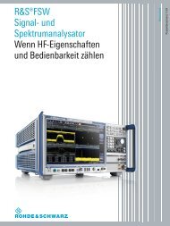
figure 2-1 shows the front panel view of the R&S <strong>FSVR</strong>. The individual elements<br />
are described in more detail in the subsequent sections.<br />
Fig. 2-1: Front panel of the R&S <strong>FSVR</strong><br />
No. Description See<br />
1 General device functions e.g. Change<br />
mode, Setup, Default Settings, Help.<br />
2 USB connector for external devices,<br />
e.g. keyboard, mouse<br />
chapter 2.1.1, "Function Keys on the Front<br />
Panel", on page 10<br />
chapter 2.1.3, "Connectors on the Front<br />
Panel", on page 15<br />
3 ON/OFF switch chapter 3.1.8, "Switching the Instrument On and<br />
Off", on page 31<br />
4 Touch screen; display area for measurement<br />
results<br />
chapter 2.1.2, "Touch screen display",<br />
on page 13<br />
<strong>Quick</strong> <strong>Start</strong> <strong>Guide</strong> 1311.0670.62 ─ 06<br />
9
R&S ® <strong>FSVR</strong><br />
Front and Rear Panel View<br />
Front Panel View<br />
No. Description See<br />
5 Auxiliary functions to display Windows<br />
<strong>Start</strong> menu or on-screen keyboard<br />
chapter 2.1.1, "Function Keys on the Front<br />
Panel", on page 10<br />
6 Display options for screen chapter 5.4, "Changing the Display",<br />
on page 88<br />
7 Navigation options for screen menu chapter 5.2.6, "Arrow Keys, UNDO/REDO<br />
Keys", on page 77<br />
8 Measurement control settings, e.g.<br />
frequency, levels<br />
chapter 2.1.1, "Function Keys on the Front<br />
Panel", on page 10<br />
9 Marker functions chapter 2.1.1, "Function Keys on the Front<br />
Panel", on page 10<br />
10 Measurement configuration chapter 2.1.1, "Function Keys on the Front<br />
Panel", on page 10<br />
11 Measurement start chapter 2.1.1, "Function Keys on the Front<br />
Panel", on page 10<br />
12 Numeric keyboard, units and data<br />
entry keys<br />
chapter 5.2.4, "Keypad", on page 76<br />
13 Rotary knob chapter 5.2.5, "Rotary Knob", on page 77<br />
14 Arrow keys chapter 5.2.6, "Arrow Keys, UNDO/REDO<br />
Keys", on page 77<br />
15 Undo/redo functions chapter 5.2.6, "Arrow Keys, UNDO/REDO<br />
Keys", on page 77<br />
16 Noise source control chapter 2.1.3, "Connectors on the Front<br />
Panel", on page 15<br />
17 Power sensor, optional chapter 2.1.4, "Optional Front Panel Connectors",<br />
on page 16<br />
18 Probe power connector - supply voltage<br />
for measurement accessories<br />
chapter 2.1.3, "Connectors on the Front<br />
Panel", on page 15<br />
19 RF input chapter 2.1.3, "Connectors on the Front<br />
Panel", on page 15<br />
2.1.1 Function Keys on the Front Panel<br />
A detailed description of the corresponding menus and the other function keys is<br />
provided in chapter 6 "Instrument Functions" of the Operating Manual.<br />
<strong>Quick</strong> <strong>Start</strong> <strong>Guide</strong> 1311.0670.62 ─ 06<br />
10
R&S ® <strong>FSVR</strong><br />
Table 2-1: Function keys<br />
Switches the instrument on and off.<br />
Front and Rear Panel View<br />
Front Panel View<br />
Resets the instrument to the default state.<br />
Provides the functions for saving/loading instrument settings and for managing<br />
stored files.<br />
Basic functionality to configure the R&S <strong>FSVR</strong>, e.g.<br />
● date and time<br />
● display configuration<br />
● LAN configuration<br />
● firmware information and update<br />
● etc.<br />
Configuration of the printout and the printer.<br />
Displays the Online Help.<br />
Mode selection<br />
Opens the Windows <strong>Start</strong> menu<br />
Switches between the on-screen keyboard display:<br />
● at the top of the screen<br />
● at the bottom of the screen<br />
● off<br />
alphanumeric keyboard<br />
Opens a dialog box to switch screen elements on or off.<br />
Switches between maximized and split display of focus area.<br />
<strong>Quick</strong> <strong>Start</strong> <strong>Guide</strong> 1311.0670.62 ─ 06<br />
11
R&S ® <strong>FSVR</strong><br />
Front and Rear Panel View<br />
Front Panel View<br />
Switches focus area between table and diagram.<br />
Allows you to define and use softkeys to load user-specific settings files.<br />
Opens the root menu of the current operating mode.<br />
FREQ (CHANNEL)<br />
SPAN<br />
AMPT (SCALE)<br />
AUTO SET<br />
BW<br />
SWEEP<br />
TRACE<br />
TRIG<br />
MKR<br />
PEAK SEARCH<br />
MKR FUNC<br />
Sets the center frequency as well as the start and stop frequencies for the<br />
frequency range under consideration. This key is also used to set the frequency<br />
offset and the signal track function.<br />
(CHANNEL for special applications)<br />
Sets the frequency span to be analyzed.<br />
In realtime mode, the span is coupled to the RBW and restricted to 40 MHz.<br />
Sets the reference level, the displayed dynamic range, the RF attenuation<br />
and the unit for the level display.<br />
Sets the level offset and the input impedance.<br />
Activates the preamplifier (option RF Preamplifier, R&S FSV-B22).<br />
(SCALE for special applications)<br />
Enables automatic settings for level, frequency or sweep type mode.<br />
Sets the resolution bandwidth and the video bandwidth.<br />
In realtime mode, the RBW is coupled to the span. Video bandwidth is not<br />
available.<br />
Sets the sweep time and the number of measurement points. In realtime<br />
mode,the number of measurement points is fixed to 801.<br />
Selects continuous measurement or single measurement.<br />
Configures the measured data acquisition and the analysis of the measurement<br />
data.<br />
Sets the trigger mode, the trigger threshold, the trigger delay, and the gate<br />
configuration in the case of gated sweep.<br />
Sets and positions the absolute and relative measurement markers (markers<br />
and delta markers).<br />
Performs a peak search for active marker. If no marker is active, normal<br />
marker 1 is activated and the peak search is performed for it.<br />
Provides additional analysis functions of the measurement markers:<br />
● Fixed reference point for relative measurement markers (Ref Fixed)<br />
● Frequency counter (Sig Count)<br />
● Noise marker (Noise Meas)<br />
● Phase noise (Phase Noise)<br />
● n dB down function<br />
● AM/FM audio demodulation (with option R&S FSV-B3)<br />
In realtime mode, marker functions are not available.<br />
<strong>Quick</strong> <strong>Start</strong> <strong>Guide</strong> 1311.0670.62 ─ 06<br />
12
R&S ® <strong>FSVR</strong><br />
MKR⇨<br />
MEAS<br />
MEAS CONFIG<br />
LINES<br />
INPUT/OUTPUT<br />
RUN SINGLE<br />
RUN CONT<br />
UNDO<br />
REDO<br />
Front and Rear Panel View<br />
Used for search functions of the measurement markers (maximum/minimum<br />
of the trace).<br />
Assigns the marker frequency to the center frequency, and the marker level<br />
to the reference level.<br />
Restricts the search area (Search Limits) and characterizes the maximum<br />
points and minimum points (Peak Excursion).<br />
Provides the measurement functions.<br />
In spectrum mode, the following measurements are available:<br />
● Measurement of multicarrier adjacent channel power (Ch Power<br />
ACLR)<br />
● Carrier to noise spacing (C/N C/No)<br />
● Occupied bandwidth (OBW)<br />
● Spectrum emission mask measurement (Spectrum Emission Mask)<br />
● Spurious emissions (Spurious Emissions)<br />
● Measurement of time domain power (Time Domain Power)<br />
● Signal statistics: amplitude probability distribution (APD) and cumulative<br />
complementary distribution function (CCDF)<br />
● Third-order intercept point (TOI)<br />
● AM modulation depth (AM Mod Depth)<br />
In realtime mode, the following measurements are available:<br />
● Realtime Spectrum<br />
● Spectrogram<br />
● Persistence Spectrum<br />
Used to define measurement configuration.<br />
Configures display lines and limit lines.<br />
Displays softkeys for input/output functions.<br />
<strong>Start</strong>s a single new measurement (Single Sweep Mode).<br />
<strong>Start</strong>s a continuous measurement (Continuous Sweep Mode).<br />
Reverts last operation.<br />
Not available for some applications; see Release Notes for details.<br />
Repeats previously reverted operation.<br />
Front Panel View<br />
Not available for some applications; see Release Notes for details.<br />
2.1.2 Touch screen display<br />
All measurement results are displayed in the screen on the front panel. Additionally,<br />
the screen display provides status and setting information and allows you to switch<br />
between various measurement tasks. The screen is touch-sensitive, offering an<br />
alternative means of user interaction for quick and easy handling of the device.<br />
<strong>Quick</strong> <strong>Start</strong> <strong>Guide</strong> 1311.0670.62 ─ 06<br />
13
R&S ® <strong>FSVR</strong><br />
Front and Rear Panel View<br />
Front Panel View<br />
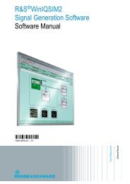
The figure 2-2 shows the touch screen display of the R&S <strong>FSVR</strong>. The individual<br />
elements are described in more detail in chapter 5, "Basic Operations",<br />
on page 64.<br />
Fig. 2-2: Touch screen elements<br />
1 = Toolbar with standard application functions, e.g. print, save/open file etc.<br />
2 = Tabs for individual measurement tasks<br />
3 = Channel information bar for current measurement settings<br />
4 = Diagram header with diagram-specific (trace) information<br />
5 = Measurement results area<br />
6 = Diagram footer with diagram-specific information, depending on measurement mode<br />
7 = Error indicator<br />
8 = Error message, if available<br />
9 = Device status<br />
10 = Progress bar for measurement<br />
11 = Date and time display<br />
12 = Softkeys for menu access<br />
<strong>Quick</strong> <strong>Start</strong> <strong>Guide</strong> 1311.0670.62 ─ 06<br />
14
R&S ® <strong>FSVR</strong><br />
Front and Rear Panel View<br />
Front Panel View<br />
2.1.3 Connectors on the Front Panel<br />
This section describes the front connectors and interfaces of the R&S <strong>FSVR</strong>.<br />
Optional connectors and interfaces are indicated by the option name in brackets.<br />
Most connectors on the front panel (except for USB) are located at the bottom righthand<br />
side.<br />
2.1.3.1 USB<br />
The front panel provides two female USB connectors to connect devices like keyboard<br />
(recommended: R&S PSL-Z2, order number 1157.6870.03) and mouse (recommended:<br />
R&S PSL-Z10, order number 1157.7060.03). Also a memory stick can<br />
be connected to store and reload instrument settings and measurement data.<br />
EMI impact on measurement results<br />
Electromagnetic interference (EMI) can affect the measurement results. To<br />
avoid any impact, make sure that the following conditions are met:<br />
●<br />
●<br />
●<br />
●<br />
Use suitable double-shielded cables.<br />
Do not use USB connecting cables exceeding 1 m in length.<br />
Use only USB devices that remain within the permissible EMI limits.<br />
Always terminate any connected IEC-bus cables with an instrument or<br />
controller.<br />
2.1.3.2 NOISE SOURCE CONTROL<br />
The noise source control female connector is used to provide the supply voltage for<br />
an external noise source, e.g., to measure the noise figure and gain of amplifiers<br />
and frequency converting DUTs.<br />
Conventional noise sources require a voltage of +28 V in order to be switched on<br />
and 0 V to be switched off. The output supports a maximum load of 100 mA.<br />
2.1.3.3 RF INPUT 50Ω<br />
The RF input is to be connected to the DUT via a cable equipped with an appropriate<br />
connector.<br />
<strong>Quick</strong> <strong>Start</strong> <strong>Guide</strong> 1311.0670.62 ─ 06<br />
15
R&S ® <strong>FSVR</strong><br />
Front and Rear Panel View<br />
Front Panel View<br />
Risk of instrument damage<br />
Do not overload the input. For maximum allowed values, see the data sheet.<br />
For AC-coupling, a DC input voltage of 50 V must never be exceeded. For<br />
DC-coupling, DC voltage must not be applied at the input. In both cases,<br />
noncompliance will destroy the input mixers.<br />
2.1.3.4 PROBE POWER<br />
The R&S <strong>FSVR</strong> provides a connector for supply voltages of +15 V<br />
to -12 V and ground for active probes and preamplifiers. A maximum<br />
current of 140 mA is available. This connector is suitable as power<br />
supply for high-impedance probes from Agilent.<br />
2.1.4 Optional Front Panel Connectors<br />
2.1.4.1 AF OUTPUT (Audio Demodulator option, R&S FSV-B3)<br />
Headphones equipped with a miniature jack plug can be connected to the AF output<br />
female connector. The internal impedance is 10 Ω. The output voltage can be set<br />
by using the volume control to the right of the female connector. If a plug is connected,<br />
the internal loudspeaker is automatically switched off.<br />
The female connector and volume control are available only with the audio demodulator<br />
option (R&S FSV-B3). To use the AF OUTPUT, in the "In-/Output" menu<br />
(INPUT/OUTPUT key), select "Video Output". The output voltage (volume) is 1V.<br />
Risk of hearing damage<br />
To protect your hearing, make sure that the volume setting is not too high<br />
before putting on the headphones.<br />
<strong>Quick</strong> <strong>Start</strong> <strong>Guide</strong> 1311.0670.62 ─ 06<br />
16
R&S ® <strong>FSVR</strong><br />
Front and Rear Panel View<br />
Front Panel View<br />
2.1.4.2 POWER SENSOR (Additional Interfaces option, R&S FSV-B5)<br />
The LEMOSA female connector is used to connect power sensors of the R&S NRP-<br />
Zxy family.<br />
2.1.4.3 Connections for External Mixers (EXT MIXER, Option R&S FSV-B21)<br />
You can connect an external mixer to the LO OUT/IF IN and IF IN female connectors<br />
of an R&S <strong>FSVR</strong>30 (option R&S FSV-B21). Both two-port and three-port mixers can<br />
be used. Connect the mixer as follows:<br />
Use the supplied coaxial cable to feed in the LO signal. If no external mixers<br />
are connected to the R&S <strong>FSVR</strong>, cover the two front connectors LO OUT / IF<br />
IN and IF IN with the SMA caps supplied.<br />
Three-port mixer<br />
1. Connect the LO OUT / IF IN output of the R&S <strong>FSVR</strong> to the LO port of the<br />
external mixer.<br />
2. Connect the IF IN input of the R&S <strong>FSVR</strong> to the IF port of the external mixer.<br />
3. Feed the signal to be measured to the RF input of the external mixer.<br />
<strong>Quick</strong> <strong>Start</strong> <strong>Guide</strong> 1311.0670.62 ─ 06<br />
17
R&S ® <strong>FSVR</strong><br />
Two-port mixer<br />
Front and Rear Panel View<br />
Rear Panel View<br />
1. 1. Connect the LO OUT / IF IN output of the R&S <strong>FSVR</strong> to the LO/IF port of the<br />
external mixer. The nominal LO level is 15.5 dBm.<br />
Because of the diplexer contained in the R&S <strong>FSVR</strong>, the IF signal can be tapped<br />
from the line which is used to feed the LO signal to the mixer.<br />
2. Feed the signal to be measured to the RF input of the external mixer.<br />
2.2 Rear Panel View<br />
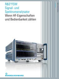
figure 2-3 shows the rear panel view of the R&S <strong>FSVR</strong>. The individual elements are<br />
described in more detail in the subsequent sections. Optional connectors and interfaces<br />
are indicated by the option name in brackets.<br />
<strong>Quick</strong> <strong>Start</strong> <strong>Guide</strong> 1311.0670.62 ─ 06<br />
18
R&S ® <strong>FSVR</strong><br />
Front and Rear Panel View<br />
Rear Panel View<br />
Fig. 2-3:<br />
1 = LAN<br />
2 = EXT TRIGGER / GATE IN<br />
3 = MONITOR (VGA)<br />
4 = REF IN<br />
5 = REF OUT<br />
6 = GPIB interface<br />
7 = AC Power Supply Connection and Main Power Switch with fuse<br />
2.2.1 Standard Rear Panel Connectors<br />
2.2.1.1 AC Power Supply Connection and Main Power Switch<br />
An AC power supply connector and main power switch are located in a unit on the<br />
rear panel of the instrument.<br />
Main power switch function:<br />
Position 1: The instrument is in operation.<br />
Position O: The entire instrument is disconnected from the AC power supply.<br />
For details refer to section “2.1.5 Switching the Instrument on and off” on page 70.<br />
<strong>Quick</strong> <strong>Start</strong> <strong>Guide</strong> 1311.0670.62 ─ 06<br />
19
R&S ® <strong>FSVR</strong><br />
Front and Rear Panel View<br />
Rear Panel View<br />
Warm-up time for OCXO<br />
When the instrument is switched on, the OCXO requires an extended warmup<br />
time (see data sheet). No warm-up time is required when starting from<br />
standby mode.<br />
2.2.1.2 LAN<br />
The LAN interface can be used to connect the R&S <strong>FSVR</strong> to a local network for<br />
remote control, printouts and data transfer. The assignment of the RJ-45 connector<br />
supports twisted-pair category 5 UTP/STP cables in a star configuration (UTP<br />
stands for unshielded twisted pair, and STP for shielded twisted pair).<br />
2.2.1.3 MONITOR (VGA)<br />
The female VGA connector is used to connect an external monitor. Step-by-step<br />
instructions how to connect an external monitor are provided in chapter 3.3, "Connecting<br />
an External Monitor", on page 36.<br />
2.2.1.4 EXT TRIGGER / GATE IN<br />
The female connector for external trigger/gate input is used to control the measurement<br />
by means of an external signal. The voltage levels can range from 0.5 to 3.5<br />
V. The default value is 1.4 V. The typical input impedance is 10 kΩ.<br />
2.2.1.5 REF IN<br />
As a reference signal, you can either use the internal reference, or connect an<br />
external one. The setup menu is used to switch between the internal and an external<br />
reference. The REF IN female connector is used as an input for a 1-20 MHz reference<br />
signal. The required input level is 0-10 dBm.<br />
2.2.1.6 REF OUT<br />
This connector can be used to provide an external reference signal (e.g. the OCXO<br />
or ultra high precision reference signal) to other devices that are connected to this<br />
instrument. The REF OUT female connector can output a 10 MHz reference signal<br />
with an output level of 0 dBm.<br />
<strong>Quick</strong> <strong>Start</strong> <strong>Guide</strong> 1311.0670.62 ─ 06<br />
20
R&S ® <strong>FSVR</strong><br />
2.2.1.7 GPIB interface<br />
Front and Rear Panel View<br />
Rear Panel View<br />
The GPIB interface is in compliance with IEEE488 and SCPI. A computer for remote<br />
control can be connected via this interface. To set up the connection, a shielded<br />
cable is recommended. For more details refer to chapter 7 "Remote Control<br />
Basics" in the Operating Manual.<br />
2.2.2 Optional Rear Panel Connectors<br />
2.2.2.1 OCXO option (R&S FSV-B4)<br />
This option generates a very precise 10 MHz reference signal with an output level<br />
of ≥ 0 dBm. If installed, and if no external signal or ultra high precision reference is<br />
used, this signal is used as an internal reference. It can also be used to synchronize<br />
other connected devices via the REF OUT connector.<br />
Warm-up time for OCXO<br />
When the instrument is switched on, the OCXO requires an extended warmup<br />
time (see data sheet). No warm-up time is required when starting from<br />
standby mode.<br />
2.2.2.2 TRIGGER OUTPUT (Additional Interfaces option, R&S FSV-B5)<br />
The female BNC connector can be used to provide a signal to another device. The<br />
signal is TTL compatible (0 V / 5 V). The "Trigger out" softkey in the "In-/Output"<br />
menu (INPUT/OUTPUT key) is used to control the trigger output.<br />
The trigger output also controls signals by the frequency mask trigger available in<br />
realtime mode.<br />
2.2.2.3 IF/VIDEO (Additional Interfaces option, R&S FSV-B5)<br />
The female BNC connector can be used for various outputs:<br />
●<br />
●<br />
Intermediate frequency (IF) output of approximately 20 MHz<br />
Video output (1V)<br />
<strong>Quick</strong> <strong>Start</strong> <strong>Guide</strong> 1311.0670.62 ─ 06<br />
21
R&S ® <strong>FSVR</strong><br />
Front and Rear Panel View<br />
Rear Panel View<br />
The "In-/Output" menu (INPUT/OUTPUT key) is used to select between the IF and<br />
video output.<br />
2.2.2.4 USB (Additional Interfaces option, R&S FSV-B5)<br />
The rear panel provides two additional female USB connectors to connect devices<br />
like keyboard (recommended: R&S PSL-Z2, order number 1157.6870.03) and<br />
mouse (recommended: R&S PSL-Z10, order number 1157.7060.03). Also, a memory<br />
stick can be connected to store and reload instrument settings and measurement<br />
data.<br />
EMI impact on measurement results<br />
Electromagnetic interference (EMI) can affect the measurement results. To<br />
avoid any impact, make sure that the following conditions are met:<br />
●<br />
●<br />
●<br />
●<br />
Use suitable double-shielded cables.<br />
Do not use USB connecting cables exceeding 1 m in length.<br />
Use only USB devices that remain within the permissible EMI limits.<br />
Always terminate any connected IEC-bus cables with an instrument or<br />
controller.<br />
2.2.2.5 AUX PORT (Additional Interfaces option, R&S FSV-B5)<br />
The 9 pole SUB-D male connector provides control signals for controlling external<br />
devices. The voltage levels are of the TTL type (5 V).<br />
Pin Signal Description<br />
1 +5 V / max. 250 mA Supply voltage for external circuits<br />
2 to 7 I/O Control lines for user ports (see User<br />
manual)<br />
8 GND Ground<br />
9 READY FOR TRIGGER Signal indicating that the instrument<br />
is ready to receive a trigger signal<br />
(Low active = 0 V)<br />
<strong>Quick</strong> <strong>Start</strong> <strong>Guide</strong> 1311.0670.62 ─ 06<br />
22
R&S ® <strong>FSVR</strong><br />
Front and Rear Panel View<br />
Rear Panel View<br />
Short-circuit hazard<br />
Always observe the designated pin assignment. A short-circuit may damage<br />
the instrument.<br />
2.2.2.6 Digital Baseband Interface (R&S FSV-B17) and R&S EX-IQ-BOX<br />
The R&S <strong>FSVR</strong> Digital Baseband Interface option (R&S FSV-B17) provides an<br />
online digital I/Q data interface on the rear panel of the instrument for input and<br />
output. The digital input and output can be enabled in the base unit or in one of the<br />
applications (where available).<br />
Optionally, an R&S EX-IQ-BOX can be connected to the Digital Baseband Interface<br />
to convert signal properties and the transmission protocol of the R&S <strong>FSVR</strong> into<br />
user-defined or standardized signal formats and vice versa.<br />
The latest R&S EX-IQ-BOX (model 1409.5505K04) provides the configuration software<br />
R&S DigIConf which can be installed directly on the R&S <strong>FSVR</strong>. The software<br />
R&S DigIConf (Digital Interface Configurator for the R&S EX-IQ-BOX, version 2.10<br />
or higher) controls the protocol, data and clock settings of the R&S EX-IQ-BOX<br />
independently from the connected R&S instrument. Besides basic functions of the<br />
user-defined protocols, this software utility supports the settings for standardized<br />
protocols, as e.g. CPRI, OBSAI or DigRF. The R&S EX-IQ-BOX requires a USB<br />
connection (not LAN!) to the R&S <strong>FSVR</strong> in addition to the Digital Baseband<br />
Interface connection.<br />
A setup file, included in delivery, covers an installation wizard, the executable program<br />
and all necessary program and data files. The latest software versions can be<br />
downloaded free of charge from the R&S website: http://www2.rohde-schwarz.com/<br />
en/products/test_and_measurement/signal_generation/EX-IQ-Box.html. Simply<br />
execute the Setup file and follow the instructions in the installation wizard.<br />
For details on installation and operation of the R&S DigIConf software, see the<br />
"R&S®EX-IQ-BOX Digital Interface Module R&S®DigIConf Software Operating<br />
Manual".<br />
<strong>Quick</strong> <strong>Start</strong> <strong>Guide</strong> 1311.0670.62 ─ 06<br />
23
R&S ® <strong>FSVR</strong><br />
3 Preparing for Use<br />
Preparing for Use<br />
Putting into Operation<br />
3.1 Putting into Operation<br />
This section describes the basic steps to be taken when setting up the R&S <strong>FSVR</strong><br />
for the first time.<br />
Risk of injury and instrument damage<br />
The instrument must be used in an appropriate manner to prevent electric<br />
shock, fire, personal injury, or damage.<br />
●<br />
●<br />
Do not open the instrument casing.<br />
Read and observe the "Basic Safety Instructions" at the beginning of this<br />
manual or on the documentation CD-ROM, in addition to the safety instructions<br />
in the following sections. Notice that the data sheet may specify<br />
additional operating conditions.<br />
Risk of instrument damage<br />
Note that the general safety instructions also contain information on operating<br />
conditions that will prevent damage to the instrument. The instrument's data<br />
sheet may contain additional operating conditions.<br />
<strong>Quick</strong> <strong>Start</strong> <strong>Guide</strong> 1311.0670.62 ─ 06<br />
24
R&S ® <strong>FSVR</strong><br />
Preparing for Use<br />
Putting into Operation<br />
Risk of instrument damage during operation<br />
An unsuitable operating site or test setup can cause damage to the instrument<br />
and to connected devices. Ensure the following operating conditions before<br />
you switch on the instrument:<br />
●<br />
●<br />
●<br />
●<br />
●<br />
●<br />
All fan openings are unobstructed and the airflow perforations are unimpeded.<br />
The minimum distance from the wall is 10 cm.<br />
The instrument is dry and shows no sign of condensation.<br />
The instrument is positioned as described in the following sections.<br />
The ambient temperature does not exceed the range specified in the data<br />
sheet.<br />
Signal levels at the input connectors are all within the specified ranges.<br />
Signal outputs are correctly connected and are not overloaded.<br />
Risk of electrostatic discharge<br />
Protect the work area against electrostatic discharge to avoid damage to<br />
electronic components in the modules. For details, refer to the safety instructions<br />
at the beginning of this manual.<br />
EMI impact on measurement results<br />
Electromagnetic interference (EMI) can affect the measurement results. To<br />
avoid any impact, make sure that the following conditions are met:<br />
●<br />
●<br />
●<br />
●<br />
Use suitable double-shielded cables.<br />
Do not use USB connecting cables exceeding 1 m in length.<br />
Use only USB devices that remain within the permissible EMI limits.<br />
Always terminate any connected IEC-bus cables with an instrument or<br />
controller.<br />
<strong>Quick</strong> <strong>Start</strong> <strong>Guide</strong> 1311.0670.62 ─ 06<br />
25
R&S ® <strong>FSVR</strong><br />
Preparing for Use<br />
Putting into Operation<br />
3.1.1 Unpacking and Checking the Instrument<br />
To remove the instrument from its packaging and check the equipment for completeness<br />
proceed as follows:<br />
1. Pull off the polyethylene protection pads from the instrument's rear feet and then<br />
carefully remove the pads from the instrument handles at the front.<br />
2. Pull off the corrugated cardboard cover that protects the rear of the instrument.<br />
3. Carefully unthread the corrugated cardboard cover at the front that protects the<br />
instrument handles and remove it.<br />
4. Check the equipment for completeness using the delivery note and the accessory<br />
lists for the various items.<br />
5. Check the instrument for any damage. If there is damage, immediately contact<br />
the carrier who delivered the instrument. Make sure not to discard the box and<br />
packing material.<br />
Packing material<br />
Retain the original packing material. If the instrument needs to be transported<br />
or shipped at a later date, you can use the material to protect the control<br />
elements and connectors.<br />
3.1.2 Accessory List<br />
The instrument comes with the following accessories:<br />
●<br />
●<br />
●<br />
Power cable<br />
<strong>Quick</strong> <strong>Start</strong> <strong>Guide</strong><br />
CD "R&S FSV Signal and Spectrum Analyzer User Documentation"<br />
3.1.3 Placing or Mounting the Instrument<br />
The R&S <strong>FSVR</strong> is designed for use under laboratory conditions, either on a bench<br />
top or in a rack.<br />
<strong>Quick</strong> <strong>Start</strong> <strong>Guide</strong> 1311.0670.62 ─ 06<br />
26
R&S ® <strong>FSVR</strong><br />
Preparing for Use<br />
Putting into Operation<br />
Bench Top Operation<br />
If the R&S <strong>FSVR</strong> is operated on a bench top, the surface should be flat. The instrument<br />
can be used in horizontal position, standing on its feet, or with the support feet<br />
on the bottom extended.<br />
Risk of injury at the operating site<br />
The feet may fold in if they are not folded out completely or if the instrument<br />
is shifted. This may cause damage or injury.<br />
●<br />
●<br />
●<br />
Fold the feet completely in or completely out to ensure stability of the<br />
instrument. Never shift the instrument when the feet are folded out.<br />
When the feet are folded out, do not work under the instrument or place<br />
anything underneath.<br />
The feet can break if they are overloaded. The overall load on the foldedout<br />
feet must not exceed 500 N.<br />
Rackmounting<br />
The R&S <strong>FSVR</strong> can be installed in a rack using a rack adapter kit (Order No. see<br />
data sheet). The installation instructions are part of the adapter kit.<br />
Risk of instrument damage in a rack<br />
An unsufficient airflow can cause the instrument to overheat, which may disturb<br />
the operation and even cause damage.<br />
Make sure that all fan openings are unobstructed, that the airflow perforations<br />
are unimpeded, and that the minimum distance from the wall is 10 cm.<br />
<strong>Quick</strong> <strong>Start</strong> <strong>Guide</strong> 1311.0670.62 ─ 06<br />
27
R&S ® <strong>FSVR</strong><br />
3.1.4 Connecting the AC Power<br />
Preparing for Use<br />
Putting into Operation<br />
In the standard version, the R&S <strong>FSVR</strong> is equipped with an AC power supply connector.<br />
The R&S <strong>FSVR</strong> can be used with different AC power voltages and adapts<br />
itself automatically to it. Refer to the datasheet for the requirements of voltage and<br />
frequency. The AC power connector is located on the rear panel of the instrument.<br />
For details on the connector refer to chapter 2.2.1.1, "AC Power Supply Connection<br />
and Main Power Switch", on page 19.<br />
► Connect the R&S <strong>FSVR</strong> to the AC power supply using the supplied power cable.<br />
Since the instrument is assembled in line with the specifications for safety class<br />
EN61010, it may only be connected to an outlet that has a ground contact.<br />
3.1.5 Changing the AC Supply Fuse<br />
Only fuses of the type IEC 60 127-T6.3H/250 V should be used. Those fuses are<br />
used for all of the specified nominal AC supply voltages.<br />
Changing the AC supply fuses:<br />
1. Disconnect the power cable.<br />
2. Open the flap covering the voltage selector using a small screwdriver (or similar).<br />
3. Remove the cylinder labelled with the nominal voltages. Remove both fuses and<br />
install the new ones. Reinsert the cylinder so that the value visible through the<br />
hole in the cover flap is the same nominal voltage as before.<br />
4. Close the flap.<br />
<strong>Quick</strong> <strong>Start</strong> <strong>Guide</strong> 1311.0670.62 ─ 06<br />
28
R&S ® <strong>FSVR</strong><br />
3.1.6 Using an Optional DC Power Supply<br />
Preparing for Use<br />
Putting into Operation<br />
When only DC power is available, for example from a battery or in a vehicle, an<br />
optional DC power supply adapter (R&S <strong>FSVR</strong>-B30) can be connected to the<br />
R&S <strong>FSVR</strong> to operate the instrument with a DC voltage of 10 V to 15 V. For installation<br />
instructions see the option's installation guide.<br />
Shock hazard due to power supply<br />
The used power supply (SELV) must fulfill the requirements for reinforced/<br />
double insulation for main supply circuits in accordance to DIN/EN/IEC 61010<br />
(UL 61010B–1, CSA C22.2 No. 1010.1) or DIN/EN/IEC 60950 (UL 1950, CSA<br />
C22.2 No. 950). Before switching on the instrument check the connection for<br />
correct polarity.<br />
Before switching on the R&S <strong>FSVR</strong>, switch on the DC power supply:<br />
Switching the DC power supply on<br />
1. Connect the R&S <strong>FSVR</strong> to the DC power source (e.g. battery pack or vehicle)<br />
using the cigarette lighter plug.<br />
2. Press the DC power switch at the DC power supply adapter to position "I". A<br />
green LED indicates that the DC power supply is ready for operation.<br />
In case of overvoltage or undervoltage, the DC power supply is automatically<br />
switched off and a red LED and a buzzer are activated.<br />
3. Press the AC power switch on the rear panel of the R&S <strong>FSVR</strong> to position "I".<br />
The instrument is supplied with AC power.<br />
Switching the DC power supply off<br />
Before you switch the DC power supply off, switch off the R&S <strong>FSVR</strong>.<br />
► Press the DC power switch at the DC power supply adapter to position "O". The<br />
DC power supply is switched off.<br />
<strong>Quick</strong> <strong>Start</strong> <strong>Guide</strong> 1311.0670.62 ─ 06<br />
29
R&S ® <strong>FSVR</strong><br />
3.1.7 Using an Optional Battery Pack<br />
Preparing for Use<br />
Putting into Operation<br />
In order to operate the R&S <strong>FSVR</strong>3 or R&S <strong>FSVR</strong>7 independently from an AC power<br />
supply, an optional battery pack can be connected (R&S <strong>FSVR</strong>-B31). The battery<br />
pack also requires the DC power supply adapter (option R&S <strong>FSVR</strong>-B30, see <br />
chapter 3.1.6, "Using an Optional DC Power Supply", on page 29).<br />
For installation instructions see the option's installation guide.<br />
Shock hazard due to power supply<br />
The used power supply (SELV) must fulfill the requirements for reinforced/<br />
double insulation for main supply circuits in accordance to DIN/EN/IEC 61010<br />
(UL 61010B–1, CSA C22.2 No. 1010.1) or DIN/EN/IEC 60950 (UL 1950, CSA<br />
C22.2 No. 950). Before switching on the instrument check the connection for<br />
correct polarity.<br />
Switching on the battery pack<br />
1. Connect the battery pack to the R&S <strong>FSVR</strong> using the cigarette lighter plug.<br />
2. Switch on the DC power supply adapter as described in "Switching the DC power<br />
supply on" on page 29.<br />
The R&S <strong>FSVR</strong> is supplied with AC power.<br />
3.1.7.1 Charging the Battery Pack<br />
The battery pack is not charged in the factory. The battery pack must be charged<br />
before it is used the first time.<br />
A new battery pack or a battery pack which has not been used for a longer<br />
time attains full capacity after several charge/ discharge cycles.<br />
The battery pack with its charger is powered from an external power supply, which<br />
is supplied with the R&S <strong>FSVR</strong>&S <strong>FSVR</strong>-B31 option. The battery pack can be<br />
charged at an ambient temperature between +10 °C and +40 °C. If the temperature<br />
is above or below these values, charging is interrupted. If the battery temperature<br />
rises above +65 °C, charging is stopped.<br />
<strong>Quick</strong> <strong>Start</strong> <strong>Guide</strong> 1311.0670.62 ─ 06<br />
30
R&S ® <strong>FSVR</strong><br />
Preparing for Use<br />
Putting into Operation<br />
1. Connect the AC adapter (24 V, 3 A) to the AC power, using the power cable<br />
supplied with the option.<br />
2. Connect the output of the AC adapter to the POWER SUPPLY 24 V connector.<br />
Note: When the AC adapter is connected the output of the battery pack is automatically<br />
switched off.<br />
The charging state is indicated by the LED labeled "CHARGE":<br />
LED state<br />
On<br />
Off<br />
Flashing<br />
Charging state<br />
Charging is in progress.<br />
Charging is completed.<br />
Error<br />
The battery temperature is outside the permissible range or the battery<br />
voltage is too low (battery deeply discharged or defective).<br />
3. Disconnect the AC adapter.<br />
The battery pack is ready for operation.<br />
After charging has been completed (LED is off), trickle charging is performed<br />
at a reduced current. Charging is terminated by an evaluation of the battery<br />
voltage (-ΔV procedure) and the battery temperature (dT/dt procedure). In<br />
addition, it is limited to approximately 6 hours by a timer.<br />
Charging should be performed at a constant ambient temperature as temperature<br />
variations may cause the charger to be switched off too early.<br />
3.1.8 Switching the Instrument On and Off<br />
Switching the instrument on<br />
If an optional DC power supply (R&S <strong>FSVR</strong>-B30) or an optional battery pack<br />
(R&S <strong>FSVR</strong>-B31) is used, you must switch on these devices first; see chapter 3.1.6,<br />
"Using an Optional DC Power Supply", on page 29 or chapter 3.1.7, "Using an<br />
Optional Battery Pack", on page 30.<br />
1. Press the AC power switch on the rear panel to position "I".<br />
The instrument is supplied with AC power.<br />
2. Press the ON/OFF key on the front panel.<br />
<strong>Quick</strong> <strong>Start</strong> <strong>Guide</strong> 1311.0670.62 ─ 06<br />
31
R&S ® <strong>FSVR</strong><br />
Preparing for Use<br />
Putting into Operation<br />
After booting, the instrument is ready for operation. A green LED above the ON/<br />
OFF key indicates this.<br />
Warm-up time for OCXO<br />
When the instrument is switched on, the OCXO requires an extended warmup<br />
time (see data sheet). No warm-up time is required when starting from<br />
standby mode.<br />
Switching the instrument off<br />
1. Press the ON/OFF key on the front panel.<br />
2. Change the AC power switch on the rear panel to position "O", or disconnect<br />
the instrument from the AC power supply.<br />
The R&S <strong>FSVR</strong> changes into off mode.<br />
Risk of losing data<br />
If you switch off the running instrument using the rear panel switch or by disconnecting<br />
the power cord, the instrument loses its current settings. Furthermore,<br />
program data may be lost.<br />
Press the ON/STANDBY key first to shut down the application properly.<br />
3.1.9 Maintenance<br />
The R&S <strong>FSVR</strong> does not require regular maintenance. Maintenance is essentially<br />
restricted to cleaning the R&S <strong>FSVR</strong>. It is however advisable to check the nominal<br />
data from time to time.<br />
<strong>Quick</strong> <strong>Start</strong> <strong>Guide</strong> 1311.0670.62 ─ 06<br />
32
R&S ® <strong>FSVR</strong><br />
Preparing for Use<br />
Putting into Operation<br />
Instrument damage caused by cleaning agents<br />
Cleaning agents contain substances that may damage the instrument, e.g.<br />
cleaning agents that contain a solvent may damage the front panel labeling<br />
or plastic parts.<br />
Never use cleaning agents such as solvents (thinners, acetone, etc), acids,<br />
bases, or other substances.<br />
The outside of the instrument can be cleaned sufficiently using a soft, lint-free<br />
dust cloth.<br />
The storage temperature range for the R&S <strong>FSVR</strong> is specified in thr data sheet. The<br />
instrument must be protected against dust if it is to be stored for a long period.<br />
When transporting or shipping the instrument, it is advisable to use the original<br />
packing material (especially the two protective covers for the front and rear panel).<br />
3.1.10 Performing a Self Alignment and a Self Test<br />
Operating temperature<br />
Before performing this functional test, make sure that the instrument has<br />
reached its operating temperature (for details, refer to the data sheet).<br />
Performing a self alignment<br />
1. Press the SETUP key.<br />
2. Press the "Alignment" softkey.<br />
3. Press the "Self Alignment" softkey.<br />
Once the system correction values have been calculated successfully, a message<br />
is displayed.<br />
<strong>Quick</strong> <strong>Start</strong> <strong>Guide</strong> 1311.0670.62 ─ 06<br />
33
R&S ® <strong>FSVR</strong><br />
Preparing for Use<br />
Connecting USB Devices<br />
To display the alignment results again later<br />
● Press the SETUP key.<br />
● Press the "Alignment" softkey.<br />
● Press the "Show Align Results" softkey.<br />
Performing a self test<br />
The self test does not need to be repeated every time the instrument is switched<br />
on. It is only necessary when instrument malfunction is suspected.<br />
1. Press the SETUP key.<br />
2. Press the "More" softkey.<br />
3. Press the "Service" softkey.<br />
4. Press the "Selftest" softkey.<br />
Once the instrument modules have been checked successfully, a message is<br />
displayed.<br />
3.1.11 Checking the Supplied Options<br />
The instrument may be equipped with both hardware and firmware options. In order<br />
to check whether the installed options correspond to the options indicated on the<br />
delivery note, proceed as follows.<br />
1. Press the SETUP key.<br />
2. Press the "System Info" softkey.<br />
3. Press the "Versions + Options" softkey.<br />
A list with hardware and firmware information is displayed.<br />
4. Check the availability of the hardware options as indicated in the delivery note.<br />
3.2 Connecting USB Devices<br />
The USB interfaces on the front and (optionally) rear panels of the R&S <strong>FSVR</strong> allow<br />
you to connect USB devices directly to the instrument. This number can be<br />
<strong>Quick</strong> <strong>Start</strong> <strong>Guide</strong> 1311.0670.62 ─ 06<br />
34
R&S ® <strong>FSVR</strong><br />
Preparing for Use<br />
increased as necessary by using USB hubs. Due to the large number of available<br />
USB devices, there is almost no limit to the expansions that are possible with the<br />
R&S <strong>FSVR</strong>.<br />
The following list shows various USB devices that can be useful:<br />
●<br />
●<br />
●<br />
●<br />
●<br />
●<br />
Memory stick for easy transfer of data to/from a computer (e.g. firmware<br />
updates)<br />
CD-ROM and DVD drives for easy installation of firmware applications<br />
Keyboard to simplify the entry of data, comments, file names, etc.<br />
Mouse for easy operation<br />
Printer for printing out measurement results<br />
Power sensors, e.g. of the NRP Zxy family<br />
Installing USB devices is easy under Windows XP, because all USB devices are<br />
plug&play. After a device is connected to the USB interface, Windows XP automatically<br />
searches for a suitable device driver.<br />
If Windows XP does not find a suitable driver, it will prompt you to specify a directory<br />
that contains the driver software. If the driver software is on a CD, connect a USB<br />
CD-ROM drive to the instrument before proceeding.<br />
When a USB device is subsequently disconnected from the R&S <strong>FSVR</strong>, Windows<br />
XP immediately detects the change in hardware configuration and deactivates the<br />
corresponding driver.<br />
All USB devices can be connected to or disconnected from the instrument during<br />
operation.<br />
Connecting a memory stick or CD-ROM drive<br />
If installation of a memory stick or CD-ROM drive is successful, Windows XP informs<br />
you that the device is ready to use. The device is made available as a new drive<br />
(D:) and is displayed under Windows Explorer. The name of the drive is manufacturer-dependent.<br />
Connecting a keyboard<br />
Connecting USB Devices<br />
The keyboard is detected automatically when it is connected. The default input language<br />
is English – US.<br />
Use the "<strong>Start</strong> > Control Panel > Keyboard" or the "Regional and Language<br />
Options" menu of Windows XP to configure the keyboard properties. To access<br />
Windows XP, press the Windows key on the external keyboard.<br />
<strong>Quick</strong> <strong>Start</strong> <strong>Guide</strong> 1311.0670.62 ─ 06<br />
35
R&S ® <strong>FSVR</strong><br />
Connecting a mouse<br />
Preparing for Use<br />
Connecting an External Monitor<br />
The mouse is detected automatically when it is connected.<br />
Use the "<strong>Start</strong> > Control Panel > Mouse" menu of Windows XP to configure the<br />
mouse properties.<br />
Connecting a printer<br />
When printing a file, the instrument checks whether a printer is connected and<br />
turned on and whether the appropriate printer driver is installed. If required, printer<br />
driver installation is initiated using Windows XP's "Add Printer" wizard. A printer<br />
driver needs to be installed only once.<br />
You can load updated and improved driver versions or new drivers from an installation<br />
disk, USB memory stick or another external storage medium. If the instrument<br />
is integrated in a network, you can also install driver data stored in a network directory.<br />
Use the "Add Printer" wizard on the "<strong>Start</strong> > Settings > Printer and Faxes" menu<br />
to install the driver. To access Windows XP, press the Windows key on the external<br />
keyboard.<br />
3.3 Connecting an External Monitor<br />
You can connect an external monitor to the "MONITOR" connector on the instrument's<br />
rear panel.<br />
For details on the connector refer to chapter 2.2.1.3, "MONITOR<br />
(VGA)", on page 20.<br />
1. Connect the external monitor to the R&S <strong>FSVR</strong>.<br />
2. Press the SETUP key.<br />
3. Press the "General Setup" softkey.<br />
4. Press the "More" softkey.<br />
5. Press the "Configure Monitor" softkey.<br />
The configuration of the connected monitor is determined and displayed in the<br />
standard Windows configuration dialog box.<br />
6. In the configuration dialog box, you can switch from the internal monitor (laptop<br />
icon) to the external monitor (monitor icon), or both (double monitor icon).<br />
<strong>Quick</strong> <strong>Start</strong> <strong>Guide</strong> 1311.0670.62 ─ 06<br />
36
R&S ® <strong>FSVR</strong><br />
Preparing for Use<br />
R&S <strong>FSVR</strong> Setup<br />
If the external monitor is selected, the R&S <strong>FSVR</strong> display is disabled. The screen<br />
content (measurement screen) formerly displayed on the R&S <strong>FSVR</strong> is displayed<br />
on the external screen. If you select both monitors, the R&S <strong>FSVR</strong> screen<br />
and the external screen are both active.<br />
3.4 R&S <strong>FSVR</strong> Setup<br />
This section describes how to setup the instrument. It includes the following topics:<br />
3.4.1 Selecting the Frequency Reference Signal...........................................37<br />
3.4.2 Setting the Date and Time.....................................................................38<br />
3.4.3 Aligning the Touch Screen.....................................................................39<br />
3.4.4 Setting the Screen Colors......................................................................40<br />
3.4.4.1 Displaying the Screen Colors Submenu................................................40<br />
3.4.4.2 Using the Default Color Settings............................................................40<br />
3.4.4.3 Using the Predefined Color Set.............................................................41<br />
3.4.4.4 Defining and Using a User-Defined Color Set.......................................42<br />
3.4.5 Setting the Display Power Save Function..............................................43<br />
3.4.6 Selecting and Configuring Printers........................................................44<br />
3.4.6.1 Configuring the Printer and the Printout................................................44<br />
3.4.6.2 Selecting the Printout Colors.................................................................45<br />
3.4.1 Selecting the Frequency Reference Signal<br />
You can switch the reference signal for frequency processing of the R&S <strong>FSVR</strong><br />
between the internal reference and an external reference signal at 10 MHz as follows:<br />
1. Press the SETUP key.<br />
2. Press the "Reference Int/Ext" softkey until it is in the desired state.<br />
<strong>Quick</strong> <strong>Start</strong> <strong>Guide</strong> 1311.0670.62 ─ 06<br />
37
R&S ® <strong>FSVR</strong><br />
Preparing for Use<br />
R&S <strong>FSVR</strong> Setup<br />
External reference signal<br />
It is important that the external reference signal is deactivated when switching<br />
from external to internal reference to avoid interactions with the internal reference<br />
signal.<br />
Remote commands:<br />
ROSC:SOUR EXT<br />
ROSC:EXT:FREQ 20<br />
3.4.2 Setting the Date and Time<br />
You can set the date and time for the internal real time clock as follows:<br />
Opening the Date and Time Properties dialog box<br />
1. Press the SETUP key.<br />
2. Press the "General Setup" softkey.<br />
3. Press the "Time + Date" softkey to open the "Date and Time Properties" dialog<br />
box.<br />
The "Date & Time" tab is displayed.<br />
Changing the date<br />
1. Press the arrow on the "Month" field to display the list.<br />
2. Select the month from the list.<br />
3. Select the year by clicking on the up and down arrow buttons next to the<br />
"Year" field.<br />
4. Select the day in the calendar display or enter the date via the keyboard.<br />
5. Click "OK".<br />
Remote command<br />
SYST:DATE 2008,10,1<br />
<strong>Quick</strong> <strong>Start</strong> <strong>Guide</strong> 1311.0670.62 ─ 06<br />
38
R&S ® <strong>FSVR</strong><br />
Changing the time<br />
Preparing for Use<br />
You can change hours, minutes and seconds independently of each other.<br />
1. Select the hour, minute or seconds area of the "Time" field.<br />
2. Enter the required setting via the keyboard or rotary knob.<br />
3. Repeat these steps until the hour, minute and second settings are correct.<br />
4. Click "OK".<br />
Remote command<br />
SYST:TIME 12,30,30<br />
Changing the time zone<br />
1. Select the "Time Zone" tab.<br />
2. Press the arrow on the "Time Zone" field to display the list.<br />
3. Select the required time zone from the list.<br />
4. Optionally, select the "Automatically adjust clock for daylight saving changes"<br />
check box.<br />
5. Click "OK".<br />
R&S <strong>FSVR</strong> Setup<br />
3.4.3 Aligning the Touch Screen<br />
When the device is delivered, the touch screen is initially aligned. However, it may<br />
become necessary to adjust the alignment later, e.g. after an image update or after<br />
exchanging a hard disk. If you notice that touching a specific point on the screen<br />
does not achieve the correct response, you may try adjusting the alignment, as well.<br />
1. Press the SETUP key.<br />
2. Press the "General Setup" softkey.<br />
3. Press the "Alignment" softkey.<br />
4. Press the "Touch Screen Alignment" softkey.<br />
5. Using a finger or any other pointing device, press the 4 markers on the screen.<br />
The touch screen is aligned according to the executed pointing operations.<br />
<strong>Quick</strong> <strong>Start</strong> <strong>Guide</strong> 1311.0670.62 ─ 06<br />
39
R&S ® <strong>FSVR</strong><br />
3.4.4 Setting the Screen Colors<br />
Preparing for Use<br />
R&S <strong>FSVR</strong> Setup<br />
To change the colors of the displayed objects, two default color settings are provided.<br />
Alternatively, you can change the color of objects individually using predefined<br />
colors or using colors of your own definition.<br />
Some color settings are defined by the selected theme, see “Selecting a<br />
Theme” on page 136, and cannot be changed individually.<br />
3.4.4.1 Displaying the Screen Colors Submenu<br />
1. Press the SETUP key.<br />
2. Press the "Display Setup" softkey.<br />
3. Press the "More" softkey.<br />
4. Press the "Screen Colors" softkey.<br />
The "Screen Colors" submenu is displayed.<br />
3.4.4.2 Using the Default Color Settings<br />
To select the default setting for brightness, tint and color saturation of all screen<br />
objects:<br />
1. In the "Screen Colors" submenu (see chapter 3.4.4.1, "Displaying the Screen<br />
Colors Submenu", on page 40), press the "Set to Default" softkey.<br />
The "Set User Colors to Default" dialog box is displayed.<br />
2. Select one of the default color sets. The color schemes are selected in such a<br />
manner that all screen elements are visible optimally regardless whether viewed<br />
from above or below. In the instrument's default setting, "Default Colors 1" is<br />
active.<br />
Remote commands:<br />
DISP:CMAP:DEF1<br />
DISP:CMAP:DEF2<br />
<strong>Quick</strong> <strong>Start</strong> <strong>Guide</strong> 1311.0670.62 ─ 06<br />
40
R&S ® <strong>FSVR</strong><br />
3.4.4.3 Using the Predefined Color Set<br />
Preparing for Use<br />
R&S <strong>FSVR</strong> Setup<br />
1. In the screen colors submenu (see chapter 3.4.4.1, "Displaying the Screen Colors<br />
Submenu", on page 40), press the "Select Screen Color Set" softkey.<br />
The "Select Screen Color Set" dialog box is displayed.<br />
2. Select the "User Defined Colors" option.<br />
3. In the screen colors submenu, press the "Select Object" softkey.<br />
The "Screen Color Setup" dialog box is displayed.<br />
4. Press the arrow on the "Selected Object" list and select the object for which you<br />
want to change the color setting.<br />
5. Select the color you want to use for the object. The defined color is displayed in<br />
the "Preview" box.<br />
6. Repeat the steps for all objects that you want to change in color.<br />
7. To change to user-defined colors, press the "Userdefined Colors" softkey. For<br />
details refer tochapter 3.4.4.4, "Defining and Using a User-Defined Color<br />
Set", on page 42.<br />
<strong>Quick</strong> <strong>Start</strong> <strong>Guide</strong> 1311.0670.62 ─ 06<br />
41
R&S ® <strong>FSVR</strong><br />
8. Click "OK" to accept the new settings and to close the dialog box.<br />
Remote command:<br />
DISP:CMAP1 ... 41:PDEF <br />
Preparing for Use<br />
R&S <strong>FSVR</strong> Setup<br />
3.4.4.4 Defining and Using a User-Defined Color Set<br />
1. In the screen colors submenu (see chapter 3.4.4.1, "Displaying the Screen Colors<br />
Submenu", on page 40), press the "Select Screen Color Set" softkey.<br />
The "Select Screen Color Set" dialog box is displayed.<br />
2. Select the "User Defined Colors" option.<br />
3. In the "Screen Colors" submenu, press the "Select Object" softkey.<br />
The "Screen Color Setup" dialog box is displayed.<br />
4. Press the arrow on the "Selected Object" list and select the object for which you<br />
want to change the color setting.<br />
5. In the color palette, select the color you want to use for the object, or enter values<br />
for tint, saturation and brightness.<br />
<strong>Quick</strong> <strong>Start</strong> <strong>Guide</strong> 1311.0670.62 ─ 06<br />
42
R&S ® <strong>FSVR</strong><br />
The defined color is displayed in the "Preview" box.<br />
Preparing for Use<br />
Note: In the continuous color spectrum ("Tint") red is represented by 0% and<br />
blue by 100%.<br />
6. Repeat the steps for all objects for which you want to change the color.<br />
7. To change to predefined colors, press the "Predefined Colors" softkey. For<br />
details refer to chapter 3.4.4.3, "Using the Predefined Color Set", on page 41.<br />
8. Click "OK" to accept the new settings and to close the dialog box.<br />
Remote command:<br />
DISP:CMAP1 ... 41:HSL ,,<br />
R&S <strong>FSVR</strong> Setup<br />
3.4.5 Setting the Display Power Save Function<br />
The R&S <strong>FSVR</strong> provides a feature for automatically switching off its screen after a<br />
user-defined period of time. The background lighting is disabled if no entries are<br />
made from the front panel after the selected response time (key, softkey and rotary<br />
knob).<br />
Activating display power save<br />
1. Press the SETUP key.<br />
2. Press the "Display Setup" softkey.<br />
3. Press the "More" softkey.<br />
4. Press the "Display Pwr Save On/Off" softkey.<br />
The power save mode is activated ("On" is highlighted), and the dialog box to<br />
enter the response time is displayed.<br />
5. Enter the desired response time in minutes and confirm the entry with the<br />
ENTER key.<br />
The screen is disabled (turns dark) after the selected period of time.<br />
Deactivating Display Power Save<br />
► In the "Display Setup" submenu, press the "Display Pwr Save On/Off" softkey<br />
again.<br />
"Off" is highlighted and the power save mode is switched off.<br />
<strong>Quick</strong> <strong>Start</strong> <strong>Guide</strong> 1311.0670.62 ─ 06<br />
43
R&S ® <strong>FSVR</strong><br />
3.4.6 Selecting and Configuring Printers<br />
Preparing for Use<br />
R&S <strong>FSVR</strong> Setup<br />
You can printout your measurement results using a local printer or a network printer.<br />
The instrument supports two independent printout settings. This allows you to<br />
quickly switch between output to a file and a printer. The procedure for installing a<br />
local printer is described in chapter 8.1, "Appendix: Printer Interface",<br />
on page 164. How to install a network printer is described in chapter 8.2.1.9,<br />
"Installing a Network Printer", on page 177.<br />
3.4.6.1 Configuring the Printer and the Printout<br />
1. Press the PRINT key.<br />
2. Press the "Device Setup" softkey.<br />
The "Hardcopy Setup" dialog box is displayed.<br />
3. To change the tab in order to define the second print setting, press the tab on<br />
the screen.<br />
4. Define the output by selecting the required options.<br />
●<br />
To save the hardcopy in an image file, select one of the image types.<br />
Depending on the image type, the color depth varies (e.g. 4-bit for BMP, 24-<br />
bit for PNG and JPEG).<br />
<strong>Quick</strong> <strong>Start</strong> <strong>Guide</strong> 1311.0670.62 ─ 06<br />
44
R&S ® <strong>FSVR</strong><br />
●<br />
●<br />
Preparing for Use<br />
To copy the image to the clipboard, select the "Clipboard" option.<br />
To use a preconfigured network printer, select the "Printer" option.<br />
Note: The "Name", "Print to File" and "Orientation" fields are only available if the<br />
"Printer" option is selected. You can perform the following steps only with the<br />
"Printer" option selected.<br />
5. In the "Name" field, select the desired printer type.<br />
6. To redirect the output to a postscript file rather than a printer, select the "Print<br />
to file" option.<br />
7. In the "Orientation" field, select the desired orientation.<br />
8. Optionally, activate the "Print Date and Time" option to add this information to<br />
the printout.<br />
9. Click "OK" to accept the settings and to close the dialog box.<br />
R&S <strong>FSVR</strong> Setup<br />
3.4.6.2 Selecting the Printout Colors<br />
1. Press the PRINT key.<br />
2. Press the "Colors" softkey.<br />
3. To print in color, press the "Select Print Color Set" softkey to select the color set.<br />
The "Select Print Color Set" dialog box is displayed.<br />
4. Select the color set by using the arrow keys and confirm your selection by<br />
pressing the ENTER key.<br />
●<br />
●<br />
"Screen Colors (Print)" option: The current screen colors are used for the<br />
printout. Independently of the current screen colors, the background is printed<br />
in white and the grid in black.<br />
Remote command: HCOP:CMAP:DEF1<br />
"Optimized Colors" option: This setting improves the color clarity of the printout.<br />
Trace 1 is printed in blue, trace 2 in black, trace 3 in bright green, trace<br />
4 in pink, trace 5 in sea green, trace 6 in dark red, and the markers in sky<br />
blue. The background is printed in white and the grid in black. The other<br />
colors correspond to the screen colors of the default color setting of the<br />
"Setup" menu.<br />
Remote command: HCOP:CMAP:DEF2<br />
<strong>Quick</strong> <strong>Start</strong> <strong>Guide</strong> 1311.0670.62 ─ 06<br />
45
R&S ® <strong>FSVR</strong><br />
●<br />
●<br />
Preparing for Use<br />
"User Defined Colors" option: You define and use your own color set for the<br />
printout. For details how to proceed refer to chapter 3.4.4.4, "Defining and<br />
Using a User-Defined Color Set", on page 42.<br />
Remote command: HCOP:CMAP:DEF3<br />
"Screen Colors (Hardcopy)" option: The current screen colors without any<br />
changes for a hardcopy. For details on the output format seechapter 3.4.6.1,<br />
"Configuring the Printer and the Printout", on page 44 .<br />
Remote command: HCOP:CMAP:DEF4<br />
5. If you want a black-and-white printout, press the "Color On/Off" softkey to switch<br />
off the color. In the black-and-white printout, all background colors are printed<br />
out in white and all color lines in black. This allows you to improve contrast on<br />
the printout.<br />
Remote command: HCOP:DEV:COL ON<br />
Windows Operating System<br />
3.5 Windows Operating System<br />
The instrument contains the Windows XP operating system which has been configured<br />
according to the instrument's features and needs. To ensure that the instrument<br />
software functions properly, certain rules must be adhered to concerning the<br />
operating system.<br />
Risk of causing instrument unusability<br />
The instrument is equipped with the Windows XP operating system. Additional<br />
software can therefore be installed on the instrument. The use and installation<br />
of additional software may impair instrument function. Thus, run only programs<br />
that <strong>Rohde</strong> & <strong>Schwarz</strong> has tested for compatibility with the instrument<br />
software.<br />
The drivers and programs used on the instrument under Windows XP have<br />
been adapted to the instrument. Existing instrument software must always be<br />
modified using only update software released by <strong>Rohde</strong> & <strong>Schwarz</strong>.<br />
The following program packages have been tested:<br />
●<br />
R&S Power Viewer - virtual power meter for displaying results of the Power<br />
Sensor R&S NRP-Zxx<br />
<strong>Quick</strong> <strong>Start</strong> <strong>Guide</strong> 1311.0670.62 ─ 06<br />
46
R&S ® <strong>FSVR</strong><br />
Preparing for Use<br />
Windows Operating System<br />
● Windows XP Remote Desktop<br />
● Symantec Norton AntiVirus – Virus-protection software<br />
● McAfee Virusscan<br />
● FileShredder - for reliable deletion of files on the hard disk<br />
3.5.1 Virus Protection<br />
Users must take appropriate steps to protect their instruments from infection. Beside<br />
the use of strong firewall settings and regularly scanning any removable storage<br />
device used with a R&S instrument, it is also recommended that anti-virus software<br />
be installed on the instrument. While <strong>Rohde</strong> & <strong>Schwarz</strong> does NOT recommend<br />
running anti-virus software in the background ("on- access" mode) on Windowsbased<br />
instruments, due to potentially degrading instrument performance, it does<br />
recommend running it during non-critical hours.<br />
For details and recommendations, see the R&S White Paper "Malware Protection"<br />
available at http://www.rohde-schwarz.com/appnote/1EF73.<br />
3.5.2 Service Packs and Updates<br />
Microsoft regularly creates security updates and other patches to protect Windowsbased<br />
operating systems. These are released through the Microsoft Update website<br />
and associated update server. Instruments using Windows, especially those that<br />
connect to a network, should be updated regularly.<br />
For more details and information on configuring automatic updates see the R&S<br />
White Paper "Malware Protection" (available at http://www.rohde-schwarz.com/<br />
appnote/1EF73).<br />
Changes in the system setup are only required when peripherals like keyboard or<br />
a printer are installed or if the network configuration does not comply with the default<br />
settings (see chapter 3.6.1, "Connecting the Instrument to the Network",<br />
on page 49). After the R&S <strong>FSVR</strong> is started, the operating system boots<br />
and the instrument firmware is started automatically.<br />
3.5.3 Login<br />
Windows XP requires that users identify themselves by entering a user name and<br />
password in a login window. You can set up two types of user accounts, either an<br />
<strong>Quick</strong> <strong>Start</strong> <strong>Guide</strong> 1311.0670.62 ─ 06<br />
47
R&S ® <strong>FSVR</strong><br />
Preparing for Use<br />
Setting Up a Network (LAN) Connection<br />
administrator account with unrestricted access to the computer/domain or a standard<br />
user account with limited access. The instrument provides an auto-login function<br />
for the administrator account, i.e. login with unrestricted access is carried out automatically<br />
in the background. By default, the user name for the administrator account<br />
is "Instrument", and the user name for the standard user account is "NormalUser".<br />
In both cases the initial password is "894129". (In firmware versions ≤ 1.50:<br />
"123456"; during a firmware update, the default password is automatically changed<br />
to "894129".) You can change the password in Windows XP for any user at any time<br />
via "Settings > Control Panel > User Accounts". Some administrative tasks require<br />
administrator rights (e.g. firmware updates or the configuration of a LAN network).<br />
Refer to the description of the softkeys in the SETUP menu to find out which functions<br />
are affected.<br />
For information on how to deactivate the automatic login, refer to chapter 8.2.1.7,<br />
"The Automatic Login Mechanism", on page 175.<br />
3.5.4 Accessing the <strong>Start</strong> Menu<br />
The Windows XP "<strong>Start</strong>" menu provides access to the Windows XP functionality<br />
and installed programs. To open the "<strong>Start</strong>" menu, press the Windows key or the<br />
CTRL + ESC key combination on your keyboard.<br />
All necessary system settings can be made in the "<strong>Start</strong> > Control Panel" menu (for<br />
required settings refer to the Windows XP manual and to the hardware description).<br />
From the "<strong>Start</strong>" menu, you can navigate to the submenus using the mouse or the<br />
cursor keys of the keyboard.<br />
3.6 Setting Up a Network (LAN) Connection<br />
The R&S <strong>FSVR</strong> is equipped with a network interface and can be connected to an<br />
Ethernet LAN (local area network). Provided the appropriate rights have been<br />
assigned by the network administrator and the Window XP firewall configuration is<br />
adapted accordingly, the interface can be used, for example:<br />
●<br />
●<br />
To transfer data between a controller and the tester, e.g. in order to run a remote<br />
control program. See chapter "Remote Control"<br />
To access or control the measurement from a remote computer using the<br />
"Remote Desktop" application (or a similar tool)<br />
<strong>Quick</strong> <strong>Start</strong> <strong>Guide</strong> 1311.0670.62 ─ 06<br />
48
●<br />
●<br />
R&S ® <strong>FSVR</strong><br />
To connect external network devices (e.g. printers)<br />
Preparing for Use<br />
To transfer data from a remote computer and back, e.g. using network folders<br />
This section describes how to configure the LAN interface. It includes the following<br />
topics:<br />
● chapter 3.6.1, "Connecting the Instrument to the Network", on page 49<br />
● chapter 3.6.2, "Assigning the IP Address", on page 50<br />
Setting Up a Network (LAN) Connection<br />
LXI<br />
The R&S <strong>FSVR</strong> complies with LXI Class C. LXI gives you direct access to the<br />
LAN settings described below.<br />
3.6.1 Connecting the Instrument to the Network<br />
There are two methods to establish a LAN connection to the instrument:<br />
●<br />
●<br />
A non-dedicated network (Ethernet) connection from the instrument to an existing<br />
network made with an ordinary RJ-45 network cable. The instrument is<br />
assigned an IP address and can coexist with a computer and with other hosts<br />
on the same network.<br />
A dedicated network connection (Point-to-point connection) between the instrument<br />
and a single computer made with a (crossover) RJ-45 network cable. The<br />
computer must be equipped with a network adapter and is directly connected to<br />
the instrument. The use of hubs, switches, or gateways is not required, however,<br />
data transfer is still performed using the TCP/IP protocol. An IP address has to<br />
be assigned to the instrument and the computer, see chapter 3.6.2, "Assigning<br />
the IP Address", on page 50.<br />
Risk of network failure<br />
Before connecting the instrument to the network or configuring the network,<br />
consult your network administrator. Errors may affect the entire network.<br />
► To establish a non-dedicated network connection, connect a commercial RJ-45<br />
cable to one of the LAN ports.<br />
To establish a dedicated connection, connect a (crossover) RJ-45 cable<br />
between the instrument and a single PC.<br />
<strong>Quick</strong> <strong>Start</strong> <strong>Guide</strong> 1311.0670.62 ─ 06<br />
49
R&S ® <strong>FSVR</strong><br />
Preparing for Use<br />
Setting Up a Network (LAN) Connection<br />
If the instrument is connected to the LAN, Windows XP automatically detects the<br />
network connection and activates the required drivers.<br />
3.6.2 Assigning the IP Address<br />
Depending on the network capacities, the TCP/IP address information for the instrument<br />
can be obtained in different ways.<br />
●<br />
●<br />
If the network supports dynamic TCP/IP configuration using the Dynamic Host<br />
Configuration Protocol (DHCP), all address information can be assigned automatically.<br />
If the network does not support DHCP, or if the instrument is set to use alternate<br />
TCP/IP configuration, the addresses must be set manually.<br />
By default, the instrument is configured to use dynamic TCP/IP configuration and<br />
obtain all address information automatically. This means that it is safe to establish<br />
a physical connection to the LAN without any previous instrument configuration.<br />
Risk of network errors<br />
Connection errors can affect the entire network. If your network does not support<br />
DHCP, or if you choose to disable dynamic TCP/IP configuration, you<br />
must assign valid address information before connecting the instrument to the<br />
LAN. Contact your network administrator to obtain a valid IP address.<br />
3.6.3 Using computer names<br />
Alternatively to the IP address, each PC or instrument connected in a LAN can be<br />
accessed via an unambiguous computer name. Each instrument is delivered with<br />
an assigned computer name, but this name can be changed.<br />
3.6.4 Changing the Windows Firewall Settings<br />
A firewall protects an instrument by preventing unauthorized users from gaining<br />
access to it through a network. <strong>Rohde</strong> & <strong>Schwarz</strong> highly recommends the use of<br />
the firewall on your instrument. R&S instruments are shipped with the Windows<br />
firewall enabled and preconfigured in such a way that all ports and connections for<br />
remote control are enabled. For more details on firewall configuration see the R&S<br />
<strong>Quick</strong> <strong>Start</strong> <strong>Guide</strong> 1311.0670.62 ─ 06<br />
50
R&S ® <strong>FSVR</strong><br />
Preparing for Use<br />
White Paper "Malware Protection" (available at http://www2.rohde-schwarz.com/<br />
file_13784/1EF73_0E.pdf) and the Windows XP help system.<br />
Note that changing firewall settings requires administrator rights.<br />
LXI Configuration<br />
3.7 LXI Configuration<br />
LAN eXtensions for Instrumentation (LXI) is an instrumentation platform for measuring<br />
instruments and test systems that is based on standard Ethernet technology.<br />
LXI is intended to be the LAN-based successor to GPIB, combining the advantages<br />
of Ethernet with the simplicity and familiarity of GPIB.<br />
Restrictions<br />
Only user accounts with administrator rights can make use of the LXI functionality.<br />
For details see the note in chapter 3.5, "Windows Operating System",<br />
on page 46.<br />
LXI Classes and LXI functionality<br />
LXI-compliant instruments are divided into three classes, A, B and C, with the functionality<br />
of the classes hierarchically based one upon the other:<br />
●<br />
Class C instruments are characterized by a common LAN implementation,<br />
including an ICMP ping responder for diagnostics. The instruments can be configured<br />
via a web browser; a LAN Configuration Initialize (LCI) mechanism resets<br />
the LAN configuration. The LXI Class C instruments shall also support automatic<br />
detection in a LAN via the VXI-11 discovery protocol and programming by means<br />
of IVI drivers.<br />
<strong>Quick</strong> <strong>Start</strong> <strong>Guide</strong> 1311.0670.62 ─ 06<br />
51
●<br />
●<br />
R&S ® <strong>FSVR</strong><br />
Preparing for Use<br />
LXI Configuration<br />
Class B adds IEEE 1588 Precision Time Protocol (PTP) and peer-to-peer communication<br />
to the base class. IEEE 1588 allows all instruments on the same<br />
network to automatically synchronize to the most accurate clock available and<br />
then provide time stamps or time-based synchronization signals to all instruments<br />
with exceptional accuracy.<br />
Class A instruments are additionally equipped with the eight-channel hardware<br />
trigger bus (LVDS interface) defined in the LXI standard.<br />
For information about the LXI standard refer to the LXI website at http://<br />
www.lxistandard.org. See also the article at the <strong>Rohde</strong>&<strong>Schwarz</strong> website:<br />
http://www2.rohde-schwarz.com/en/technologies/connectivity/LXI/information/.<br />
Instruments of classes A and B can generate and receive software triggers via LAN<br />
messages and communicate with each other without involving the controller.<br />
The R&S <strong>FSVR</strong> complies with LXI Class C. In addition to the general class C features<br />
described above, it provides the following LXI-related functionality:<br />
●<br />
Integrated "LXI Configuration" dialog box for LXI activation and reset of the LAN<br />
configuration (LAN Configuration Initialize, LCI).<br />
Firmware update<br />
After a firmware update, shut-down and re-start the instrument in order to<br />
enable the full LXI functionality.<br />
3.7.1 LXI Configuration Dialog Box<br />
This dialog box provides basic LXI functions for the R&S <strong>FSVR</strong>. "LXI Configuration"<br />
is a tab of the "System > System Configuration" dialog box.<br />
<strong>Quick</strong> <strong>Start</strong> <strong>Guide</strong> 1311.0670.62 ─ 06<br />
52
R&S ® <strong>FSVR</strong><br />
Preparing for Use<br />
LXI Configuration<br />
●<br />
●<br />
"LXI Status Enabled" switches the LXI logo in the status bar on or off.<br />
"LAN Config Initialize" initiates the network configuration reset mechanism (LCI)<br />
for the instrument.<br />
Default state of the network settings<br />
According to the LXI standard, an LCI must set the following parameters to a default<br />
state.<br />
Parameter<br />
TCP/IP Mode<br />
Dynamic DNS<br />
ICMP Ping<br />
Password for LAN configuration<br />
Value<br />
DHCP + Auto IP Address<br />
Enabled<br />
Enabled<br />
LxiWebIfc<br />
The LCI for the R&S <strong>FSVR</strong> also resets the following parameters:<br />
Parameter<br />
Hostname<br />
Description<br />
Negotiation<br />
VXI-11 Discovery<br />
Value<br />
<br />
Signal Analysis R&S <strong>FSVR</strong><br />
Auto Detect<br />
Enabled<br />
<strong>Quick</strong> <strong>Start</strong> <strong>Guide</strong> 1311.0670.62 ─ 06<br />
53
R&S ® <strong>FSVR</strong><br />
Preparing for Use<br />
LXI Configuration<br />
The LAN settings are configured using the instrument's LXI Browser Interface.<br />
3.7.2 LXI Browser Interface<br />
The instrument's LXI browser interface works correctly with all W3C compliant<br />
browsers. Typing the instrument's host name or IP address in the address field of<br />
the browser on your PC, e.g. http://10.113.10.203, opens the "Instrument Home<br />
Page" (welcome page).<br />
To check the instrument name select SETUP > "General setup" > "Computer<br />
name".<br />
To check the instrument's IP address select SETUP > "General setup" > "IP<br />
address".<br />
The "Instrument Home Page" displays the device information required by the LXI<br />
standard including the VISA resource string in read-only format.<br />
<strong>Quick</strong> <strong>Start</strong> <strong>Guide</strong> 1311.0670.62 ─ 06<br />
54
R&S ® <strong>FSVR</strong><br />
Preparing for Use<br />
LXI Configuration<br />
► Press the "Device Indicator" toggle button to activate or deactivate the LXI status<br />
indication in the status bar of the R&S <strong>FSVR</strong>. If it is active, the LXI logo blinks<br />
in the status bar. A green LXI status symbol indicates that a LAN connection has<br />
been established; a red symbol indicates that no LAN cable is connected. The<br />
"Device Indicator" setting is not password-protected.<br />
The navigation pane of the browser interface contains the following control elements:<br />
●<br />
●<br />
●<br />
"LAN Configuration" opens the LAN Configuration page.<br />
"LXI Glossary" opens a document with a glossary of terms related to the LXI<br />
standard.<br />
"Status" displays information about the LXI status of the instrument.<br />
3.7.3 LAN Configuration<br />
The "LAN Configuration" web page displays all mandatory LAN parameters and<br />
allows their modification.<br />
The "TCP/IP Mode" configuration field controls how the IP address for the instrument<br />
gets assigned (see also chapter 3.6.2, "Assigning the IP<br />
Address", on page 50). For the manual configuration mode, the static IP address,<br />
subnet mask, and default gateway are used to configure the LAN. The automatic<br />
configuration mode uses DHCP server or Dynamic Link Local Addressing (Automatic<br />
IP) to obtain the instrument IP address.<br />
Changing the LAN configuration is password-protected. The password is Lxi-<br />
WebIfc (notice upper and lower case characters). This password cannot be<br />
changed in the current firmware version.<br />
The links at the bottom of the "LAN Configuration" page open other pages:<br />
●<br />
●<br />
Advanced LAN Configuration provides LAN settings that are not declared mandatory<br />
by the LXI standard.<br />
Ping provides the ping utility to verify the connection between the instrument and<br />
other devices.<br />
<strong>Quick</strong> <strong>Start</strong> <strong>Guide</strong> 1311.0670.62 ─ 06<br />
55
R&S ® <strong>FSVR</strong><br />
3.7.3.1 Advanced LAN Configuration<br />
Preparing for Use<br />
Configuring the GPIB Interface<br />
The "Advanced LAN Configuration" parameters are used as follows:<br />
●<br />
●<br />
●<br />
The "Negotiation" configuration field provides different Ethernet speed and<br />
duplex mode settings. In general, the "Auto Detect" mode is sufficient.<br />
"ICMP Ping" must be enabled to use the ping utility.<br />
"VXI-11" is the protocol that is used to detect the instrument in the LAN. According<br />
to the standard, LXI devices must use VXI-11 to provide a detection mechanism;<br />
other additional detection mechanisms are permitted.<br />
3.7.3.2 Ping<br />
The instrument includes a ping server and a ping client. The ping client can be used<br />
to verify the connection between instrument and another device. The ping command<br />
uses the ICMP echo request and echo reply packets to determine whether the LAN<br />
connection is functional. Ping is useful for diagnosing IP network or router failures.<br />
The ping utility is not password-protected.<br />
To initiate a ping between the LXI-compliant instrument and a second connected<br />
device:<br />
1. Enable "ICMP Ping" on the "Advanced LAN Configuration" page (enabled after<br />
an LCI).<br />
2. Enter the IP address of the second device without the ping command and<br />
without any further parameters into the "Destination Address" field (e.g.<br />
10.113.10.203).<br />
3. Click "Submit".<br />
The result of the echo request is displayed if the connection was established.<br />
3.8 Configuring the GPIB Interface<br />
A GPIB interface is integrated on the rear panel of the instrument. You can set the<br />
GPIB address and the ID response string. The GPIB language is set as SCPI by<br />
default and cannot be changed for the R&S <strong>FSVR</strong>.<br />
<strong>Quick</strong> <strong>Start</strong> <strong>Guide</strong> 1311.0670.62 ─ 06<br />
56
R&S ® <strong>FSVR</strong><br />
For details on the GPIB interface see chapter 2.2.1.7, "GPIB interface",<br />
on page 21).<br />
Displaying the GPIB submenu<br />
1. 1. Press the SETUP key.<br />
2. 2. Press the "General Setup" softkey.<br />
3. 3. Press the "GPIB" softkey.<br />
Preparing for Use<br />
The submenu for setting the parameters of the remote control interface is displayed.<br />
Setting the GPIB address<br />
► In the "GPIB" menu, press the "GPIB Address" softkey.<br />
The edit dialog box for the GPIB address is displayed. The setting range is from<br />
0 to 30. If SCPI is selected as the GPIB language, the default address is 20.<br />
Remote command:<br />
SYST:COMM:GPIB:ADDR 20<br />
Setting the default ID response string<br />
► In the "GPIB" menu, press the "ID String Factory" softkey to select the default<br />
response to the *IDN? command.<br />
Setting a user-defined ID response string<br />
Remote Desktop Connection<br />
► In the "GPIB" menu, press the "ID String User" softkey to enter a user-defined<br />
response to the *IDN? command. The maximum length of the output string is<br />
36 characters.<br />
3.9 Remote Desktop Connection<br />
Remote Desktop is a Windows application which can be used to access and control<br />
the instrument from a remote computer through a LAN connection. While the instrument<br />
is in operation, the instrument screen contents are displayed on the remote<br />
computer, and Remote Desktop provides access to all of the applications, files, and<br />
network resources of the instrument. Thus, remote operation of the instrument is<br />
possible.<br />
<strong>Quick</strong> <strong>Start</strong> <strong>Guide</strong> 1311.0670.62 ─ 06<br />
57
R&S ® <strong>FSVR</strong><br />
Preparing for Use<br />
Remote Desktop Connection<br />
Risk of Unauthorized Access<br />
If the Windows Remote Desktop application is enabled on the instrument (go<br />
to "<strong>Start</strong> > Settings > Control Panel > System"), any user in the network who<br />
knows the computer name and login data can access it. To prevent this, make<br />
sure that the Remote Desktop application on the instrument is disabled.<br />
To set up a Remote Desktop connection<br />
1. Enable remote desktop control on the instrument.<br />
2. Connect the instrument and the remote computer to a LAN, see chapter 3.6.1,<br />
"Connecting the Instrument to the Network", on page 49.<br />
3. Set up the Remote Desktop connection between the remote computer and the<br />
instrument.<br />
Remote Desktop Client<br />
With Windows XP, Remote Desktop Client is part of the operating system and<br />
can be accessed via "<strong>Start</strong> > Programs > Accessories > [Communications >]<br />
Remote Desktop Connection.".<br />
For other versions of Windows, Microsoft offers the Remote Desktop Client<br />
as an add-on.<br />
Enabling remote desktop control on the instrument<br />
1. Press the "Windows" key to access the operating system.<br />
2. Open the Control Panel by selecting "<strong>Start</strong> > Settings > Control Panel".<br />
3. Select "System" and switch to the "Remote" tab.<br />
4. Under "Remote Desktop", activate the "Allow users to connect remotely to this<br />
computer" option.<br />
Note: Remote Desktop access and firewall settings.<br />
When you enable or disable the Windows Remote Desktop option (in the "System<br />
Properties"), the associated firewall settings are adapted automatically.<br />
5. If necessary, click "Select Remote Users" and select users who are to be given<br />
access to the R&S <strong>FSVR</strong> via Remote Desktop. The user account under which<br />
configuration is carried out is automatically enabled for Remote Desktop.<br />
<strong>Quick</strong> <strong>Start</strong> <strong>Guide</strong> 1311.0670.62 ─ 06<br />
58
R&S ® <strong>FSVR</strong><br />
Preparing for Use<br />
Setting up the Remote Desktop connection on the remote computer<br />
1. On the remote computer, select "<strong>Start</strong> > Programs > Accessories > [Communications<br />
>] Remote Desktop Connection."<br />
2. Enter the instrument's name or IP address in the dialog box (see also chapter<br />
3.6.2, "Assigning the IP Address", on page 50).<br />
3. Enter the user ID and password for the instrument (see also chapter 3.5, "Windows<br />
Operating System", on page 46).<br />
4. Click "Connect".<br />
When the connection has been set up, the instrument's screen appears on the<br />
remote computer.<br />
For detailed information about Remote Desktop and the connection refer to the<br />
Windows XP Help.<br />
Helpful settings for Remote Desktop<br />
The following settings for the Remote Desktop connection can make working on the<br />
remote PC more convenient.<br />
1. When setting up the connection to the instrument, you can configure the connection<br />
settings in the "Remote Desktop Connection" dialog box.<br />
Click the "Options >>" button.<br />
The dialog box is expanded to display the configuration data.<br />
2. Customize the settings:<br />
●<br />
●<br />
Remote Desktop Connection<br />
On the "Experience" tab:<br />
– Select the appropriate connection to optimize the connection speed.<br />
– To improve the performance, you can deactivate options you do not<br />
require under "Allow the following".<br />
On the "Local Resources" tab:<br />
– If you need to access drives of the remote PC from the instrument (e.g.<br />
in order to store settings or to copy files from the PC to the instrument),<br />
activate the "Disk drives" option. Windows XP will then map drives of the<br />
remote PC to the corresponding network drives. When a connection is<br />
established, a warning is displayed on the PC indicating that the drives<br />
are enabled for access from the instrument.<br />
– To use printers connected to the remote PC while accessing them from<br />
the instrument, activate the "Printers" options. Do not change the remaining<br />
settings.<br />
<strong>Quick</strong> <strong>Start</strong> <strong>Guide</strong> 1311.0670.62 ─ 06<br />
59
R&S ® <strong>FSVR</strong><br />
●<br />
●<br />
Preparing for Use<br />
On the "Display" tab:<br />
– Under "Remote desktop size", set the size of the R&S <strong>FSVR</strong> window on<br />
the desktop of the remote PC.<br />
– Activate the "Display the connection bar when in full screen mode" option.<br />
A bar showing the network address of the instrument is displayed on the<br />
screen which you can use to reduce, minimize or close the window.<br />
On the "General" tab:<br />
You can save the connection settings for later use using the "Save As" button.<br />
Terminating Remote Desktop Control<br />
Remote Desktop Connection<br />
A Remote Desktop connection can be terminated either on the R&S <strong>FSVR</strong> or on<br />
the remote PC. The connection can be established again any time as long as remote<br />
control is enabled on the instrument. Consider the notice above concerning unauthorized<br />
access due to Remote Desktop!<br />
1. To terminate the connection on the instrument, logon to the R&S <strong>FSVR</strong>.<br />
2. To terminate the connection on the remote PC, close the "Remote Desktop"<br />
window, or select "<strong>Start</strong> > Disconnect".<br />
<strong>Quick</strong> <strong>Start</strong> <strong>Guide</strong> 1311.0670.62 ─ 06<br />
60
R&S ® <strong>FSVR</strong><br />
Firmware Update and Installation of Firmware Options<br />
Firmware Update<br />
4 Firmware Update and Installation of Firmware<br />
Options<br />
This chapter describes how to update the firmware and how to activate optional<br />
firmware packages.<br />
4.1 Firmware Update<br />
You can install a new firmware version using one of the following methods:<br />
●<br />
●<br />
copying the files to the instrument using USB devices (e.g. a memory stick),<br />
GPIB, or LAN<br />
using the "Remote Installation" feature in a LAN network<br />
Copying the files to the instrument<br />
1. Press the SETUP key.<br />
The setup menu is displayed.<br />
2. Press the "More" softkey.<br />
The side menu is displayed.<br />
3. Press the "Firmware Update" softkey.<br />
The "Firmware Update" dialog box is displayed.<br />
4. Enter the drive name and directory via the keypad.<br />
Example: The installation files are stored on a memory stick in the Update<br />
directory. After you insert the memory stick, it will be detected as drive D:.<br />
Therefore, the required path specification is D:\UPDATE.<br />
5. If you install via LAN using the Remote Desktop application, enter the drive name<br />
and directory or press the "Browse" button to locate the directory:<br />
a) In the displayed dialog box, select the drive.<br />
b) On the selected drive, select the folder that contains the installation file<br />
(*.exe).<br />
c) Press the "Select" button to confirm your selection and go back to the "Firmware<br />
Update" dialog box.<br />
6. Press "Execute"<br />
The installation program will guide you through the installation.<br />
<strong>Quick</strong> <strong>Start</strong> <strong>Guide</strong> 1311.0670.62 ─ 06<br />
61
R&S ® <strong>FSVR</strong><br />
Firmware Update and Installation of Firmware Options<br />
7. After the firmware update, the "UNCAL" status display indicates the necessity<br />
of a self alignment. Perform a self alignment (for details refer to chapter 3.1.10,<br />
"Performing a Self Alignment and a Self Test", on page 33).<br />
Remote command: SYST:FIRM:UPD 'D:\FW_UPDATE'<br />
Performing a remote installation from a Windows PC<br />
This method requires a LAN connection from the instrument to a Windows PC (see<br />
chapter 3.6, "Setting Up a Network (LAN) Connection", on page 48).<br />
1. Run FSVSetup.exe on your PC.<br />
2. Select "Remote Installation" and click the "Next" button.<br />
3. Select the packages you want to install and click the "Next" button.<br />
4. Your LAN subnet is scanned and all found instruments are listed.<br />
Note: The FSVSetup.exe command communicates with the instrument via<br />
LAN, which means the command must pass the firewall. Therefore, add the<br />
command to your firewall rules, then restart the scan by clicking "Rescan".<br />
5. Select the instruments you want to update. You can select up to 5 instruments<br />
to update at the same time.<br />
Note: All instruments in your LAN structure are included in the list. Make sure<br />
you select the correct instruments!<br />
To display further options, click the "Options" button.<br />
6. <strong>Start</strong> installation by clicking "Install".<br />
Activating Firmware Options<br />
7. Confirm that you want to reboot the instrument in order to activate the firmware<br />
update. The instrument restarts automatically.<br />
4.2 Activating Firmware Options<br />
Firmware options are enabled by entering license keys as described here.<br />
To activate firmware options<br />
1. Press the SETUP key.<br />
2. Press the "More" softkey.<br />
3. Press the "Option Licenses" softkey.<br />
<strong>Quick</strong> <strong>Start</strong> <strong>Guide</strong> 1311.0670.62 ─ 06<br />
62
R&S ® <strong>FSVR</strong><br />
4. Press the "Install Option" softkey.<br />
An edit dialog box is displayed.<br />
Firmware Update and Installation of Firmware Options<br />
5. Enter the option key number using the keypad.<br />
6. Press the ENTER key.<br />
If validation is successful, the message "option key valid" is displayed. If the<br />
validation fails, the option software is not installed.<br />
7. Reboot the instrument.<br />
Activating Firmware Options<br />
With time-limited licenses, a message box appears if an option is about to<br />
expire. Press the "OK" button to resume using the R&S <strong>FSVR</strong>. If an option<br />
has already expired, a message box appears for you to confirm. In this case,<br />
all instrument functions are unavailable (including remote control) until the<br />
R&S <strong>FSVR</strong> is rebooted.<br />
Alternatively, options can be activated using an XML file.<br />
To activate firmware options using an XML file<br />
1. Press the SETUP key.<br />
2. Press the "More" softkey.<br />
3. Press the "Option Licenses" softkey.<br />
4. Press the "Install Option by XML" softkey.<br />
An edit dialog box is displayed.<br />
5. Enter or browse for the name of an XML file on the instrument that contains the<br />
option key.<br />
6. Press "Select."<br />
If validation is successful, the message "option key valid" is displayed. If the<br />
validation fails, the option software is not installed.<br />
7. Reboot the instrument.<br />
<strong>Quick</strong> <strong>Start</strong> <strong>Guide</strong> 1311.0670.62 ─ 06<br />
63
R&S ® <strong>FSVR</strong><br />
5 Basic Operations<br />
Basic Operations<br />
Information in the Diagram Area<br />
This chapter gives an overview on how to work with the R&S <strong>FSVR</strong>. It describes<br />
what kind of information is displayed in the diagram area, how to operate the<br />
R&S <strong>FSVR</strong> via the front panel keys and other interaction methods, and how to use<br />
the Online Help.<br />
Note the chapter 5, "Basic Operations", on page 64 concerning procedure<br />
descriptions and terminology described at the beginning of this manual.<br />
5.1 Information in the Diagram Area<br />
The following figure shows a measurement diagram during analyzer operation. All<br />
different information areas are labeled. They are explained in more detail in the<br />
following sections.<br />
1 = Operation mode tabs<br />
2 = Hardware information<br />
3 = Header of the result display containing trace information<br />
4 = Result display<br />
<strong>Quick</strong> <strong>Start</strong> <strong>Guide</strong> 1311.0670.62 ─ 06<br />
64
R&S ® <strong>FSVR</strong><br />
5 = Footer of the result display containing general measurement settings<br />
6 = Calibration status<br />
7 = Error messages<br />
8 = Measurement status information<br />
9 = Measurement progress bar<br />
10 = Date and time<br />
11 = Softkeys<br />
Basic Operations<br />
Information in the Diagram Area<br />
5.1.1 Channel Display<br />
Using the R&S <strong>FSVR</strong> you can handle several different measurement tasks (channels)<br />
at the same time (although they can only be performed asynchronously). For<br />
each channel, a separate tab is displayed on the screen. In order to switch from one<br />
channel display to another, simply press the corresponding tab.<br />
The icon on the tab label indicates that the displayed trace no longer<br />
matches the current instrument settings. This may be the case, for example,<br />
if a trace is frozen and the instrument settings are changed. As soon as a new<br />
measurement is performed, the icon disappears.<br />
To start a new channel<br />
1. Click the icon in the toolbar at the top of the screen (see also chapter 5.2.1,<br />
"Toolbar", on page 73 on how to display the toolbar).<br />
2. Select the softkey for the required measurement mode.<br />
A new tab is displayed for the new channel.<br />
5.1.2 Display of Hardware Settings<br />
Information on hardware settings are displayed in the channel bar above the diagram.<br />
<strong>Quick</strong> <strong>Start</strong> <strong>Guide</strong> 1311.0670.62 ─ 06<br />
65
R&S ® <strong>FSVR</strong><br />
Basic Operations<br />
Invalid settings<br />
A bullet next to the hardware setting indicates that user-defined settings are<br />
used, not automatic settings. A green bullet indicates this setting is valid and<br />
the measurement is correct. A red bullet indicates an invalid setting that does<br />
not provide useful results.<br />
It is the user's responsibility to remedy such a situation.<br />
Information in the Diagram Area<br />
Editing settings in the channel bar<br />
All settings that are displayed in the channel bar can easily be edited by<br />
touching the setting in the display (with a finger or mouse pointer). The corresponding<br />
(edit) dialog box is displayed where you can edit the setting.<br />
In realtime mode, the R&S <strong>FSVR</strong> shows the following settings:<br />
Ref Level<br />
m.+el.Att<br />
SWT<br />
RBW<br />
Current reference level.<br />
Current mechanical and electronic RF attenuation.<br />
Current sweep time.<br />
Current resolution bandwidth.<br />
In spectrum mode, the R&S <strong>FSVR</strong> shows the following settings:<br />
Ref Level<br />
m.+el.Att<br />
Ref Offset<br />
SWT<br />
RBW<br />
VBW<br />
Compatible<br />
Reference level<br />
Mechanical and electronic RF attenuation that has been set.<br />
Reference level offset<br />
Sweep time that has been set.<br />
If the sweep time does not correspond to the value for automatic<br />
coupling, a bullet is displayed in front of the field. The color of the<br />
bullet turns red if the sweep time is set below the value for automatic<br />
coupling. In addition, the UNCAL flag is shown. In this case, the<br />
sweep time must be increased.<br />
Resolution bandwidth that has been set.<br />
If the bandwidth does not correspond to the value for automatic<br />
coupling, a green bullet appears in front of the field.<br />
Video bandwidth that has been set.<br />
If the bandwidth does not correspond to the value for automatic<br />
coupling, a green bullet is displayed in front of the field.<br />
Compatible device mode (FSP, FSU, default; default not displayed)<br />
<strong>Quick</strong> <strong>Start</strong> <strong>Guide</strong> 1311.0670.62 ─ 06<br />
66
R&S ® <strong>FSVR</strong><br />
Mode<br />
Mod<br />
AQT<br />
DBW<br />
Dig Out<br />
Basic Operations<br />
Indicates which sweep mode type is selected:<br />
● "Auto FFT": automatically selected FFT sweep mode<br />
● "Auto sweep": automatically selected swept sweep mode<br />
● "FFT": manually selected FFT sweep mode<br />
● "Sweep": manually selected swept sweep mode<br />
Analog demodulation mode (AM/FM/PM)<br />
Information in the Diagram Area<br />
Acquisition time for ACP/CCDF measurements (when using analog<br />
demodulation mode).<br />
Demodulation bandwidth (when using analog demodulation mode).<br />
State of digital output, option R&S FSV-B17 only<br />
5.1.3 Measurement Settings Information<br />
In addition to the common hardware settings, the channel bar above the diagram<br />
also displays information on instrument settings that affect the measurement results<br />
even though this is not immediately apparent from the display of the measured values.<br />
This information is displayed in gray font and only when applicable for the<br />
current measurement, as opposed to the common hardware settings that are<br />
always displayed.<br />
The following types of information may be displayed, if applicable.<br />
SGL<br />
Sweep<br />
Count<br />
TRG<br />
6dB/<br />
RRC/<br />
CHN<br />
The sweep is set to single sweep mode.<br />
The current signal count for measurement tasks that involve a specific number of subsequent<br />
sweeps<br />
(see "Sweep Count" setting in "Sweep" menu in the Operating manual)<br />
Trigger source<br />
(for details see trigger settings in the "TRIG" menu in the Operating manual)<br />
● EXT: External<br />
● VID: Video<br />
● RFP: RF power<br />
● IFP: IF power<br />
● TIM: Time<br />
Filter type for sweep bandwidth<br />
(see BW menu in the Operating manual)<br />
This label is available in spectrum mode.<br />
<strong>Quick</strong> <strong>Start</strong> <strong>Guide</strong> 1311.0670.62 ─ 06<br />
67
R&S ® <strong>FSVR</strong><br />
Basic Operations<br />
Information in the Diagram Area<br />
PA<br />
GAT<br />
TDF<br />
The preamplifier is activated.<br />
The frequency sweep is controlled via the EXT TRIG/GATE IN connector.<br />
A transducer factor is activated.<br />
75 Ω The input impedance of the instrument is set to 75 Ω.<br />
FRQ<br />
DC/AC<br />
Inp<br />
A frequency offset ≠ 0 Hz is set.<br />
An external DC or AC calibration signal is in use.<br />
Input source: digital I/Q (option R&S FSV-B17 only)<br />
5.1.4 Diagram-specific and Trace Information<br />
Diagram-specific information, e.g. concerning traces, is indicated in the diagram<br />
header and footer.<br />
Trace information in diagram header<br />
The diagram header (above the diagram) contains the following trace information:<br />
The header may contain a user-defined introductory title, see chapter 5.4.7,<br />
"Adding a Title to the Diagram Header", on page 95.<br />
Editing settings in the diagram header<br />
All settings that are displayed in the diagram header can easily be edited by<br />
selecting the setting in the display (by tapping or clicking). The corresponding<br />
(edit) dialog box is displayed in which you can edit the setting.<br />
Norm/NCor<br />
Correction data is not used.<br />
Trace color<br />
Color of trace display in diagram<br />
Trace no. Trace number (1 to 6)<br />
Detector<br />
Selected detector:<br />
AP<br />
AUTOPEAK detector<br />
<strong>Quick</strong> <strong>Start</strong> <strong>Guide</strong> 1311.0670.62 ─ 06<br />
68
R&S ® <strong>FSVR</strong><br />
Basic Operations<br />
Information in the Diagram Area<br />
Trace Mode<br />
Pk<br />
Mi<br />
Sa<br />
Av<br />
Rm<br />
QP<br />
Clrw<br />
Max<br />
Min<br />
Avg<br />
View<br />
MAX PEAK detector<br />
MIN PEAK detector<br />
SAMPLE detector<br />
AVERAGE detector<br />
RMS detector<br />
QUASIPEAK detector<br />
Sweep mode:<br />
CLEAR/WRITE<br />
MAX HOLD<br />
MIN HOLD<br />
AVERAGE (Lin/Log/Pwr)<br />
VIEW<br />
Marker information in Diagram Grid<br />
The x and y axis positions of the last 2 markers or delta markers that were set, as<br />
well as their index, are displayed within the diagram grid, if available. The value in<br />
the square brackets after the index indicates the trace to which the marker is<br />
assigned. (Example: M1[1] defines marker 1 on trace 1.) For more than 2 markers,<br />
a separate marker table is displayed beneath the diagram.<br />
The marker function information is not available in realtime mode.<br />
If applicable, the active measurement function for the marker and its main results<br />
are indicated, as well. The functions are indicated with the following abbreviations:<br />
FXD<br />
PHNoise<br />
CNT<br />
TRK<br />
NOIse<br />
MDepth<br />
TOI<br />
Reference fixed marker active<br />
Phase noise measurement active<br />
Frequency counter active<br />
Signal track active<br />
Noise measurement active<br />
Measurement of the AM modulation depth active<br />
TOI measurement active<br />
<strong>Quick</strong> <strong>Start</strong> <strong>Guide</strong> 1311.0670.62 ─ 06<br />
69
R&S ® <strong>FSVR</strong><br />
Marker Information in Marker Table<br />
Basic Operations<br />
Information in the Diagram Area<br />
In addition to the marker information displayed within the diagram grid, a separate<br />
marker table may be displayed beneath the diagram. This table provides the following<br />
information for all active markers:<br />
Type<br />
Dgr<br />
Trc<br />
Stimulus<br />
Response<br />
Func<br />
Func .Result<br />
Marker type: N (normal), D (delta), T (temporary, internal), PWR (power<br />
sensor)<br />
Diagram number<br />
Trace to which the marker is assigned<br />
x-value of the marker<br />
y-value of the marker<br />
Activated marker or measurement function<br />
Result of the active marker or measurement function<br />
Mode-dependant Information in Diagram Footer<br />
The diagram footer (beneath the diagram) contains the following information,<br />
depending on the current mode:<br />
Mode Label Information<br />
FREQ CF Center frequency (between start and stop)<br />
Span<br />
Frequency span<br />
SPAN CF (1.0 ms/) Zero span<br />
For most modes, the number of sweep points shown in the display are indicated in<br />
the diagram footer. In zoom mode, the (rounded) number of currently displayed<br />
points are indicated.<br />
The diagram footer can be removed from the display temporarily, see chapter 5.4.8,<br />
"Removing the Diagram Footer", on page 95.<br />
5.1.5 Instrument and Status Information<br />
Global instrument settings, the instrument status and any irregularities are indicated<br />
in the status bar beneath the diagram.<br />
<strong>Quick</strong> <strong>Start</strong> <strong>Guide</strong> 1311.0670.62 ─ 06<br />
70
R&S ® <strong>FSVR</strong><br />
Basic Operations<br />
Information in the Diagram Area<br />
Hiding the status bar<br />
You can hide the status bar display, e.g. in order to enlarge the display area<br />
for the measurement results.<br />
1. Press the DISPLAY key.<br />
2. In the "Display Settings" dialog box, select "Status Bar State: Off".<br />
The status bar is no longer displayed.<br />
●<br />
To display the status bar again, select "Status Bar State: On".<br />
SCPI command:<br />
DISP:SBAR:STAT OFF<br />
The following information is displayed:<br />
Instrument status<br />
The instrument is configured for operation with an external reference.<br />
The optional Digital Baseband interface (B17) is being used for digital input<br />
The optional Digital Baseband interface (B17) is being used to provide digital<br />
output<br />
Error information<br />
If errors or irregularities are detected, a keyword and an error message, if available,<br />
are displayed in the status bar.<br />
The following keywords are used:<br />
UNCAL<br />
OVLD<br />
IFOVL<br />
One of the following conditions applies:<br />
● Correction data has been switched off.<br />
● No correction values are available. This occurs, for example, if a firmware<br />
update is performed followed by a cold start of the instrument.<br />
● Record the correction data by performing a self alignment<br />
Overload of the input mixer.<br />
● Increase the RF attenuation (for RF input).<br />
● Reduce the input level (for digital input)<br />
Overload of the IF signal path after the input mixer.<br />
● Increase the reference level.<br />
<strong>Quick</strong> <strong>Start</strong> <strong>Guide</strong> 1311.0670.62 ─ 06<br />
71
R&S ® <strong>FSVR</strong><br />
LOUNL<br />
NO REF<br />
OVEN<br />
FIFO OVL<br />
Basic Operations<br />
Error in the instrument's frequency processing hardware was detected.<br />
Instrument was set to an external reference but no signal was detected on the<br />
reference input.<br />
OCXO reference frequency (option R&S FSV-B4) has not yet reached its<br />
operating temperature. The message usually disappears a few minutes after<br />
power has beeen switched on.<br />
for option R&S FSV-B17 only<br />
Means of User Interaction<br />
Progress<br />
The progress of the current operation is displayed in the status bar.<br />
Date and time<br />
The date and time settings of the instrument are displayed in the status bar.<br />
5.2 Means of User Interaction<br />
The instrument provides a user interface for operation that does not require an<br />
external keyboard, using the following means of interaction:<br />
● chapter 5.2.1, "Toolbar", on page 73<br />
● chapter 5.2.2, "Touch Screen", on page 74<br />
● chapter 5.2.3, "On-screen Keyboard", on page 75<br />
● chapter 5.2.5, "Rotary Knob", on page 77<br />
● chapter 5.2.6, "Arrow Keys, UNDO/REDO Keys", on page 77<br />
● chapter 5.2.7, "Softkeys", on page 78<br />
● chapter 5.2.9, "Dialog Boxes", on page 81<br />
All tasks necessary to operate the instrument can be performed using this user<br />
interface. Apart from instrument specific keys, all other keys that correspond to an<br />
external keyboard (e.g. arrow keys, ENTER key) operate conform to Microsoft.<br />
For most tasks, there are at least 2 alternative methods to perform them:<br />
●<br />
Using the touch screen<br />
<strong>Quick</strong> <strong>Start</strong> <strong>Guide</strong> 1311.0670.62 ─ 06<br />
72
●<br />
R&S ® <strong>FSVR</strong><br />
Basic Operations<br />
Means of User Interaction<br />
Using other elements provided by the front panel, e.g. the keypad, rotary knob,<br />
or arrow and position keys<br />
5.2.1 Toolbar<br />
Standard functions can be performed via the icons in the toolbar at the top of the<br />
screen, if available (see chapter 5, "Basic Operations", on page 64). By default, this<br />
toolbar is not displayed.<br />
Displaying the toolbar<br />
► Press the "Toolbar" icon to the right of the tabs in the display to toggle the toolbar<br />
on or off.<br />
Alternatively:<br />
1. Press the SETUP key.<br />
2. Press the "Display Setup" softkey.<br />
3. Press the "Tool Bar State On/Off" softkey.<br />
Or:<br />
4. Press the DISPLAY key.<br />
5. In the "Display Settings" dialog box, select "Tool Bar State: On".<br />
The toolbar is displayed at the top of the screen.<br />
Remote:<br />
DISP:TBAR:STAT ON<br />
The following functions are available:<br />
Table 5-1: Standard Application Functions in the Toolbar<br />
Icon<br />
Description<br />
Opens the "Select Mode" menu (see chapter 5.1.1, "Channel Display", on page 65)<br />
Opens an existing measurement (settings) file<br />
<strong>Quick</strong> <strong>Start</strong> <strong>Guide</strong> 1311.0670.62 ─ 06<br />
73
R&S ® <strong>FSVR</strong><br />
Basic Operations<br />
Means of User Interaction<br />
Icon<br />
Description<br />
Stores the current measurement file<br />
Prints the current measurement screen<br />
Saves the current measurement screen as a file (screenshot)<br />
Reverts last operation.<br />
Repeats previously reverted operation.<br />
Selection mode: the cursor can be used to select (and move) markers in a zoomed<br />
display<br />
Zoom mode: displays a dotted rectangle in the diagram that can be expanded to define<br />
the zoom area. Can be repeated several times.<br />
Zoom off: the diagram is displayed in its original size<br />
5.2.2 Touch Screen<br />
A touch screen is a screen that is touch-sensitive, i.e. it reacts in a specified way<br />
when a particular element on the screen is tapped by a finger or a pointing device,<br />
for example. Any user interface elements that can be clicked on by a mouse pointer<br />
can also be tapped on the screen to trigger the same behavior, and vice versa.<br />
Using the touch screen, the following tasks (amoung others) can be performed by<br />
the tap of your finger:<br />
●<br />
●<br />
●<br />
●<br />
●<br />
Changing a setting<br />
Changing the display<br />
Moving a marker<br />
Zooming into a diagram<br />
Saving or printing results and settings<br />
To imitate a right-click by mouse using the touch screen, for example to open a<br />
context-sensitive menu for a specific item, press the screen for about 1 second.<br />
Deactivating and Activating the Touch Screen Function<br />
The touch screen function can be deactivated, e.g. when the instrument is being<br />
used for demonstration purposes and tapping the screen should not provoke an<br />
action.<br />
1. Press the DISPLAY key.<br />
2. In the dialog box, select one of the following options:<br />
<strong>Quick</strong> <strong>Start</strong> <strong>Guide</strong> 1311.0670.62 ─ 06<br />
74
R&S ® <strong>FSVR</strong><br />
●<br />
●<br />
●<br />
Basic Operations<br />
"TOUCH SCREEN ON": touch screen function is active for the entire screen<br />
"TOUCH SCREEN OFF": touch screen is deactivated for the entire screen<br />
"DIAGRAM TOUCH OFF": touch screen is deactivated for the diagram area<br />
of the screen, but active for the surrounding softkeys, toolbars and menus.<br />
SCPI command:<br />
DISP:TOUCh:STAT OFF<br />
Means of User Interaction<br />
5.2.3 On-screen Keyboard<br />
The on-screen keyboard is an additional means of interacting with the instrument<br />
without having to connect an external keyboard.<br />
The on-screen keyboard display can be switched on and off as desired using the<br />
"On-Screen Keyboard" function key beneath the screen.<br />
When you press this key, the display switches between the following options:<br />
●<br />
●<br />
●<br />
Keyboard displayed at the top of the screen<br />
Keyboard displayed at the bottom of the screen<br />
No keyboard displayed<br />
You can use the TAB key on the on-screen keyboard to move the focus from<br />
one field to another in dialog boxes.<br />
<strong>Quick</strong> <strong>Start</strong> <strong>Guide</strong> 1311.0670.62 ─ 06<br />
75
R&S ® <strong>FSVR</strong><br />
5.2.4 Keypad<br />
Basic Operations<br />
Means of User Interaction<br />
The keypad is used to enter alphanumeric parameters. It contains the<br />
following keys:<br />
● Alphanumeric keys<br />
Enters numbers and (special) characters in edit dialog boxes. For<br />
details refer to chapter 5.3.1, "Entering Numeric Parameters",<br />
on page 82 and chapter 5.3.2, "Entering Alphanumeric<br />
Parameters", on page 83.<br />
● Decimal point<br />
Inserts a decimal point "." at the cursor position.<br />
●<br />
●<br />
●<br />
●<br />
●<br />
Sign key<br />
Changes the sign of a numeric parameter. In the case of an alphanumeric<br />
parameter, inserts a "-" at the cursor position.<br />
Unit keys (GHz/-dBm MHz/dBm, kHz/dB and Hz/dB)<br />
These keys add the selected unit to the entered numeric value and complete<br />
the entry.<br />
In the case of level entries (e.g. in dB) or dimensionless values, all units have<br />
the value "1" as mulitplying factor. Thus, they have the same function as an<br />
ENTER key. The same is true for an alphanumeric entry.<br />
ESC key<br />
Closes all kinds of dialog boxes, if the edit mode is not active. Quits the edit<br />
mode, if the edit mode is active. In dialog boxes that contain a "Cancel" button<br />
it activates that button.<br />
For "Edit" dialog boxes the following mechanism is used:<br />
– If data entry has been started, it retains the original value and closes the<br />
dialog box.<br />
– If data entry has not been started or has been completed, it closes the dialog<br />
box.<br />
BACKSPACE key<br />
– If an alphanumeric entry has already been started, this key deletes the character<br />
to the left of the cursor.<br />
– If no input field is currently active, the most recently entered value is undone,<br />
i.e. the previous value is retrieved. Thus, you can toggle between two values<br />
(e.g. spans).<br />
ENTER key<br />
– Concludes the entry of dimensionless entries. The new value is accepted.<br />
– With other entries, this key can be used instead of the "Hz/dB" unit key.<br />
<strong>Quick</strong> <strong>Start</strong> <strong>Guide</strong> 1311.0670.62 ─ 06<br />
76
R&S ® <strong>FSVR</strong><br />
– In a dialog box, presses the default or focused button.<br />
Basic Operations<br />
Means of User Interaction<br />
– In a dialog box, activates the edit mode for the focused area, if available. For<br />
details on the edit mode refer to chapter 5.3.3, "Navigating in Dialog<br />
Boxes", on page 85.<br />
– In a dialog box, activates or deactivates the selected option of the focused<br />
area, if the edit mode is active.<br />
5.2.5 Rotary Knob<br />
The rotary knob has several functions:<br />
● Increments (clockwise direction) or decrements (counter-clockwise<br />
direction) the instrument parameter at a defined step width in the<br />
case of a numeric entry.<br />
● Shifts the selection bar within focused areas (e.g. lists), if the edit<br />
mode is activated.<br />
● Shifts markers, limit lines, etc on the screen.<br />
● Acts like the ENTER key, when it is pressed. For details refer to <br />
chapter 5.3.3, "Navigating in Dialog Boxes", on page 85.<br />
● Moves the scroll bar vertically, if the scroll bar is focused and the edit<br />
mode is activated.<br />
For details on the edit mode refer to chapter 5.3.3, "Navigating in Dialog<br />
Boxes", on page 85.<br />
5.2.6 Arrow Keys, UNDO/REDO Keys<br />
The arrow keys are used for navigation. The UNDO/REDO keys support you during<br />
input.<br />
UPARROW/DNARROW keys<br />
The UPARROW or DNARROW keys do the following:<br />
●<br />
●<br />
●<br />
In a numeric edit dialog box, increase or decrease the instrument parameter.<br />
In a list, scroll forward and backward through the list entries.<br />
In a table, move the selection bar vertically.<br />
<strong>Quick</strong> <strong>Start</strong> <strong>Guide</strong> 1311.0670.62 ─ 06<br />
77
R&S ® <strong>FSVR</strong><br />
Basic Operations<br />
Means of User Interaction<br />
●<br />
In windows or dialog boxes with vertical scroll bar, move the scroll bar.<br />
LEFTARROW/RIGHTARROW keys<br />
The LEFTARROW or RIGHTARROW keys do the following:<br />
●<br />
●<br />
●<br />
●<br />
In an alphanumeric edit dialog box, move the cursor.<br />
In a list, scroll forward and backward through the list entries.<br />
In a table, move the selection bar horizontally.<br />
In windows or dialog boxes with horizontal scroll bar, move the scroll bar.<br />
UNDO/REDO keys<br />
●<br />
●<br />
The UNDO key reverts the previously performed action, i.e. the status before<br />
the previous action is retrieved.<br />
The undo function is useful, for example, if you are performing a zero span<br />
measurement with several markers and a limit line defined and accidentally click<br />
the "ACP" softkey. In this case, very many settings would be lost. However, if<br />
you press UNDO immediately afterwards, the previous status is retrieved, i.e.<br />
the zero span measurement and all settings.<br />
The REDO key repeats the previously reverted action, i.e. the most recently<br />
performed action is repeated.<br />
The UNDO function is not available after a PRESET or "RECALL" operation.<br />
When these functions are used, the history of previous actions is deleted.<br />
The UNDO/REDO functions are not available for some applications; see<br />
Release Notes for details.<br />
5.2.7 Softkeys<br />
Softkeys are virtual keys provided by the software. Thus, more functions can be<br />
provided than those that can be accessed directly via the function keys on the<br />
device. Softkeys are dynamic, i.e. depending on the selected function key, a different<br />
list of softkeys is displayed on the right side of the screen<br />
A list of softkeys for a certain function key is also called a menu. Each softkey can<br />
either represent a specific function, or a submenu that in turn represents several<br />
softkeys.<br />
<strong>Quick</strong> <strong>Start</strong> <strong>Guide</strong> 1311.0670.62 ─ 06<br />
78
R&S ® <strong>FSVR</strong><br />
Selecting softkeys<br />
Basic Operations<br />
Means of User Interaction<br />
► A particular softkey is selected by pressing the key on the screen with a finger,<br />
mouse pointer or other pointing device.<br />
Softkeys can only be operated via the screen, there are (usually) no corresponding<br />
function keys.<br />
Navigating in softkey menus<br />
●<br />
●<br />
●<br />
●<br />
The "More" softkey indicates that the menu contains more softkeys than can be<br />
displayed at once on the screen. When pressed, it displays the next set of softkeys.<br />
If the softkey label contains a ">" symbol, it represents a submenu of further<br />
softkeys. When you press it, the submenu is displayed.<br />
The "Up" key switches to the next higher level of the menu.<br />
The start menu of the current measurement mode is accessed directly by pressing<br />
the HOME key on the front panel.<br />
Softkey actions<br />
A softkey performs one of the following actions when pressed:<br />
●<br />
●<br />
●<br />
Opens a dialog box to enter data.<br />
Switches a function on or off.<br />
Opens a submenu (only softkeys with a ">" symbol).<br />
Recognizing the softkey status by color<br />
In the factory configuration, a softkey is highlighted orange when a corresponding<br />
dialog box is open. If it is a toggle softkey, the current state is highlighted blue. If an<br />
instrument function is not available temporarily due to a specific setting, the associated<br />
softkey is deactivated and its text is colored gray.<br />
Some softkeys belong to a certain (firmware) option. If this option is not implemented<br />
in your device, the associated softkeys are not displayed.<br />
Hiding softkeys<br />
You can hide the softkey display, e.g. when using remote control, in order to enlarge<br />
the display area for the measurement results. When you press a function key on<br />
the front panel, the softkeys are displayed temporarily, enabling you to perform a<br />
<strong>Quick</strong> <strong>Start</strong> <strong>Guide</strong> 1311.0670.62 ─ 06<br />
79
R&S ® <strong>FSVR</strong><br />
Basic Operations<br />
certain task with the softkeys. They are then automatically hidden again when they<br />
have not been used for a specified time. Any edit dialog boxes required for entry<br />
remain in the display.<br />
1. Press the DISPLAY key.<br />
2. In the "Display Settings" dialog box, select "Softkey Bar State: Off".<br />
The softkeys are no longer displayed.<br />
► To display the softkeys again, select "Softkey Bar State: On".<br />
Remote:<br />
DISP:SKEY:STAT OFF<br />
Means of User Interaction<br />
5.2.8 Context-sensitive Menus<br />
Markers and traces in the display, as well as the information in the channel bar,<br />
have context-sensitive menus. If you right-click on a marker or trace in the display,<br />
or information in the channel bar (or touch it for about 1 second), a menu is displayed<br />
which contains the same functions as the corresponding softkey. This is useful, for<br />
example, when the softkey display is hidden (see chapter 5.2.7, "Softkeys",<br />
on page 78).<br />
<strong>Quick</strong> <strong>Start</strong> <strong>Guide</strong> 1311.0670.62 ─ 06<br />
80
R&S ® <strong>FSVR</strong><br />
Basic Operations<br />
Means of User Interaction<br />
If a menu entry contains an arrow to the right of it, a submenu is available for that<br />
entry.<br />
► To close the menu, press the ESC key or click in the display outside of the menu.<br />
5.2.9 Dialog Boxes<br />
In most cases, the R&S <strong>FSVR</strong> dialog boxes are designed to enter a numeric value.<br />
In the documentation, these dialog boxes are called "edit dialog boxes". Dialog<br />
boxes that are not only designed for parameter entry have a more complex structure<br />
and, in the documentation, are called "dialog boxes". The navigation in Windows<br />
dialog boxes differs in some aspects from the navigation in R&S <strong>FSVR</strong> dialog boxes.<br />
For details, see chapter 5.3.3, "Navigating in Dialog Boxes", on page 85.<br />
The following figure shows an example of a edit dialog box:<br />
<strong>Quick</strong> <strong>Start</strong> <strong>Guide</strong> 1311.0670.62 ─ 06<br />
81
R&S ® <strong>FSVR</strong><br />
Basic Operations<br />
Setting Parameters<br />
Fig. 5-1: Edit dialog box for parameter entry<br />
The title bar shows the name of the parameter that was selected. The entry is performed<br />
in the editing line. When the dialog box is displayed, the focus is on the<br />
editing line and it contains the currently used parameter value and its unit. The<br />
optional third line shows status and error messages which always refer to the current<br />
entry.<br />
5.3 Setting Parameters<br />
This section describes how to perform the following basic tasks in the R&S <strong>FSVR</strong>:<br />
● chapter 5.3.1, "Entering Numeric Parameters", on page 82<br />
● chapter 5.3.2, "Entering Alphanumeric Parameters", on page 83<br />
● chapter 5.3.3, "Navigating in Dialog Boxes", on page 85<br />
5.3.1 Entering Numeric Parameters<br />
If a field requires numeric input, the keypad provides only numbers.<br />
1. Enter the parameter value using the keypad, or change the currently used<br />
parameter value by using the rotary knob (small steps) or the UPARROW or<br />
DNARROW keys (large steps).<br />
2. After entering the numeric value via keypad, press the corresponding unit key.<br />
The unit is added to the entry.<br />
3. If the parameter does not require a unit, confirm the entered value by pressing<br />
the ENTER key or one of the unit keys.<br />
The editing line is highlighted in order to confirm the entry.<br />
<strong>Quick</strong> <strong>Start</strong> <strong>Guide</strong> 1311.0670.62 ─ 06<br />
82
R&S ® <strong>FSVR</strong><br />
5.3.2 Entering Alphanumeric Parameters<br />
Basic Operations<br />
Setting Parameters<br />
If a field requires alphanumeric input, you can use the on-screen keyboard to enter<br />
numbers and (special) characters (see also chapter 5.2.3, "On-screen Keyboard",<br />
on page 75).<br />
Fig. 5-2: On-screen keyboard<br />
Alternatively, you can use the keypad. Every alphanumeric key provides several<br />
characters and one number. The decimal point key (.) provides special characters,<br />
and the sign key (-) toggles between capital and small letters. For the assignment<br />
refer to table 5-2. In principle, the input of alphanumeric parameters works like writing<br />
an SMS on your cell phone.<br />
Entering numbers and (special) characters via the keypad<br />
1. Press the key once to enter the first possible value.<br />
2. All characters available via this key are displayed in a popup.<br />
3. To choose another value provided by this key, press the key again, until your<br />
desired value is displayed.<br />
4. With every key stroke the next possible value of this key is displayed. If all possible<br />
values have been displayed, the series starts with the first value again. For<br />
information on the series refer to table 5-2.<br />
5. To change from capital to small letters and vice versa, press the sign key (-).<br />
6. When you have chosen the desired value, wait for 2 seconds (to use the same<br />
key again), or start the next entry by pressing another key.<br />
<strong>Quick</strong> <strong>Start</strong> <strong>Guide</strong> 1311.0670.62 ─ 06<br />
83
R&S ® <strong>FSVR</strong><br />
Basic Operations<br />
Setting Parameters<br />
Entering a blank<br />
► Press the "Space" bar, or press the "0" key and wait 2 seconds.<br />
Correcting an entry:<br />
1. Using the arrow keys, move the cursor to the right of the entry you want to delete.<br />
2. Press the BACKSPACE key.<br />
3. The entry to the left of the cursor is deleted.<br />
4. Enter your correction.<br />
Completing the entry<br />
► Press the ENTER key or the rotary knob.<br />
Aborting the entry<br />
► Press the ESC key.<br />
The dialog box is closed without changing the settings.<br />
Table 5-2: Keys for alphanumeric parameters<br />
Key name<br />
(upper inscription)<br />
Series of (special) characters and number provided<br />
7 7 µ Ω ° € ¥ $ ¢<br />
8 A B C 8 Ä ÆÅ Ç<br />
9 D E F 9 É<br />
4 G H I 4<br />
5 J K L 5<br />
6 M N O 6 Ň Ö<br />
1 P Q R S 1<br />
2 T U V 2 Ü<br />
3 W X Y Z 3<br />
0 0 – @ + / \ < > = % &<br />
<strong>Quick</strong> <strong>Start</strong> <strong>Guide</strong> 1311.0670.62 ─ 06<br />
84
R&S ® <strong>FSVR</strong><br />
Basic Operations<br />
Setting Parameters<br />
Key name<br />
(upper inscription)<br />
Series of (special) characters and number provided<br />
. . * : _ , ; " ' ? ( ) #<br />
– <br />
5.3.3 Navigating in Dialog Boxes<br />
Some of the dialog boxes are not only for parameter entry, and therefore have a<br />
more complex structure. The following figure shows an example.<br />
Changing the focus<br />
The focus on the graphical user interface is moved by pressing an element on the<br />
screen, or via the rotary knob. The focused area is marked with a blue frame (see <br />
figure 5-3). If this area consists of more than one element, e.g. lists of options or<br />
tables, you must first switch to the edit mode in order to make changes. A focused<br />
area in the edit mode is marked with a dashed blue frame (see figure 5-4).<br />
<strong>Quick</strong> <strong>Start</strong> <strong>Guide</strong> 1311.0670.62 ─ 06<br />
85
R&S ® <strong>FSVR</strong><br />
Basic Operations<br />
Setting Parameters<br />
Fig. 5-3: Focused area<br />
Fig. 5-4: Focused area in edit mode<br />
Edit mode<br />
When using the touch screen for focus changes, all focused areas are in the<br />
edit mode automatically, if available. Otherwise, you must switch to edit mode<br />
manually.<br />
Switching to edit mode<br />
1. Press the ENTER key.<br />
2. To quit the edit mode, press the ESC key.<br />
Working in dialog boxes<br />
●<br />
To edit alphanumeric parameters, use the keypad or the on-screen keyboard.<br />
For details see chapter 5.3.1, "Entering Numeric Parameters", on page 82 and <br />
<strong>Quick</strong> <strong>Start</strong> <strong>Guide</strong> 1311.0670.62 ─ 06<br />
86
●<br />
●<br />
●<br />
●<br />
●<br />
●<br />
●<br />
●<br />
●<br />
R&S ® <strong>FSVR</strong><br />
Basic Operations<br />
chapter 5.3.2, "Entering Alphanumeric Parameters", on page 83. If you edit<br />
fields, the edit mode is activated automatically when you start typing.<br />
To move the focus to the next interface element (e.g. field, option, list), press it<br />
on the screen, or turn the rotary knob.<br />
To select or deselect an option, press the option on the screen.<br />
Alternatively:<br />
– If the focused area consists of more than one option and the edit mode is not<br />
active, change into the edit mode.<br />
– Scroll through the list of options using the arrow keys or the rotary knob (only<br />
for vertical direction) until the option you want to activate or deactivate is<br />
highlighted.<br />
– Press the rotary knob or the ENTER key to confirm your selection.<br />
The option is activated or deactivated, depending on its previous setting.<br />
– To leave the edit mode, press the ESC key.<br />
To open a drop-down list, press the arrow next to the list. Alternatively, press<br />
the ENTER key or the rotary knob. When opened, the list is in edit mode.<br />
To select an entry without opening a drop-down list, use the arrow keys to<br />
browse through the list entries.<br />
To select a list entry, press the entry on the screen.<br />
Alternatively:<br />
– If the edit mode is not active, change into the edit mode.<br />
– Scroll through the list using the arrow keys or the rotary knob until the list<br />
entry you want to select is highlighted.<br />
– Confirm your choice by pressing the rotary knob or the ENTER key.<br />
If a drop-down list was opened, it is closed.<br />
To change from one tab to the next, press the tab on the screen.<br />
To press a button in a dialog box, press the button on the screen.<br />
Alternatively:<br />
– Place the focus on the desired button using the rotary knob.<br />
Setting Parameters<br />
– Confirm your choice by pressing the rotary knob or the ENTER key.<br />
To close the dialog box and accept the changes, press the "OK" button.<br />
To close the dialog box without accepting the changes, press the ESC key or<br />
the "Cancel" button.<br />
<strong>Quick</strong> <strong>Start</strong> <strong>Guide</strong> 1311.0670.62 ─ 06<br />
87
R&S ® <strong>FSVR</strong><br />
Particularities in Windows dialog boxes<br />
Basic Operations<br />
In some cases, e.g. if you want to install a printer, original Windows dialog boxes<br />
are used. In these dialog boxes, the navigation behavior is different to the one you<br />
are used to from R&S <strong>FSVR</strong> applications. In the following, the important differences<br />
and useful tips are listed:<br />
●<br />
Changing the Display<br />
The rotary knob and function keys do not work. Do not use them. Use the touch<br />
screen instead.<br />
5.4 Changing the Display<br />
5.4.1 Changing the Focus<br />
Any selected function is always performed on the currently focussed element in the<br />
display, e.g. a dialog field, diagram, or table row. Which element is focussed is<br />
indicated by a blue frame (diagram, window, table) or is otherwise highlighted (softkey,<br />
marker etc.). Moving the focus is most easily done by tapping on the element<br />
on the touch screen. Alternatively, use the "Tab" key on the on-screen keyboard or<br />
the rotary knob to move the focus from one element to the next on the display.<br />
To move the focus on the screen between any displayed diagrams or tables, press<br />
the "Change focus" function key on the front panel. The focus moves from the diagram<br />
to the first table to the next table etc. and then back to the diagram.<br />
5.4.2 Switching between Split and Maximized Display<br />
In some measurement modes, a table with markers or measurement results<br />
is displayed beneath the diagram. In this case, you may wish to maximize<br />
the diagram or table display in order to see more details.<br />
Press the SPLIT/MAXIMIZE key on the front panel to switch between full and maximized<br />
display. In maximized display, the table or diagram currently focused is maximized.<br />
In split display, both the diagram and any available tables are displayed in<br />
one screen.<br />
<strong>Quick</strong> <strong>Start</strong> <strong>Guide</strong> 1311.0670.62 ─ 06<br />
88
R&S ® <strong>FSVR</strong><br />
Remote: DISP:WIND:SIZE LARG<br />
Basic Operations<br />
Changing the Display<br />
5.4.3 Soft and Mini Soft Front Panel Display<br />
When working with an external monitor or operating via remote control on a computer,<br />
it is useful to be able to interact with the R&S <strong>FSVR</strong> without requiring the<br />
keypad and keys located on the front panel of the instrument. Therefore, a "Soft<br />
Front Panel" display is available, which simulates the entire front panel of the instrument<br />
(except for the external connectors) on the screen. You can switch between<br />
"normal" screen display and extended display. In the extended display, the keys<br />
and other hardware controls of the instrument are simulated on the screen.<br />
If you require a Soft Front Panel but do not want to lose too much space for results<br />
in the display area, a mini soft Front Panel is available. The mini version displays<br />
only the hardkeys in a separate window in the display area. This window can be<br />
closed automatically after pressing a key, or remain open, as desired. Using the<br />
Mini Front Panel, the R&S <strong>FSVR</strong> interface is fully operable from a monitor with a<br />
resolution of 1024x768 pixels.<br />
Switching to soft Front Panel display<br />
1. Press the SETUP key.<br />
2. Press the "General Setup" softkey.<br />
3. Press the "More" softkey.<br />
4. Press the "Soft Front Panel" softkey.<br />
Alternatively:<br />
5. Press the DISPLAY key.<br />
6. In the "Display Settings" dialog box, select "Front Panel State: On".<br />
The extended display appears on the screen.<br />
<strong>Quick</strong> <strong>Start</strong> <strong>Guide</strong> 1311.0670.62 ─ 06<br />
89
R&S ® <strong>FSVR</strong><br />
Basic Operations<br />
Changing the Display<br />
Using the F6 key you can toggle the Front Panel display on and off.<br />
Remote: SYST:DISP:FPAN:STAT ON<br />
Working with the Soft Front Panel<br />
Basic operation with the soft Front Panel is identical to normal operation. To activate<br />
a key, either press the key on the touch screen, or click on it with the mouse pointer.<br />
To simulate the use of the rotary knob, use the additional keys displayed between<br />
the keypad and the arrow keys:<br />
Icon<br />
Function<br />
Turn left<br />
Enter<br />
Turn right<br />
Switching to Mini Front Panel display<br />
1. Press the DISPLAY key.<br />
<strong>Quick</strong> <strong>Start</strong> <strong>Guide</strong> 1311.0670.62 ─ 06<br />
90
R&S ® <strong>FSVR</strong><br />
Basic Operations<br />
Changing the Display<br />
2. In the "Display Settings" dialog box, select "Mini Front Panel State: On".<br />
The "Mini Front Panel" window appears on the screen. It can be moved anywhere<br />
on the screen where it does not interfere with your current task.<br />
Using the key combination ALT + M you can toggle the Mini Front Panel display<br />
on and off.<br />
Auto close option<br />
By default, the "Auto close" option is activated and the Mini Front Panel window<br />
closes automatically after you select a key. This is useful if you only require the<br />
Front Panel display to press a single function key.<br />
If you want the window to remain open, deactivate the "Auto close" option. You can<br />
close the window manually by clicking "Close Panel" or the key combination ALT +<br />
M.<br />
<strong>Quick</strong> <strong>Start</strong> <strong>Guide</strong> 1311.0670.62 ─ 06<br />
91
R&S ® <strong>FSVR</strong><br />
Basic Operations<br />
Changing the Display<br />
5.4.4 Enlarging the Display Area<br />
You can enlarge the screen display area if you are using an external monitor<br />
or the chapter 5.4.3, "Soft and Mini Soft Front Panel Display", on page 89.<br />
To do so, drag the lower right corner of the window to the required size. In<br />
standard display, a small icon is displayed in the lower right corner of the<br />
screen.<br />
5.4.5 Displaying the Toolbar<br />
Standard file functions can be performed via the icons in the toolbar at the top of<br />
the screen (see the chapter 5.2.1, "Toolbar", on page 73). By default, this toolbar is<br />
not displayed.<br />
To display the toolbar:<br />
1. Press the DISPLAY key.<br />
2. Under "Select Tool Bar State", select "On".<br />
a) or:<br />
1. Press the SETUP key.<br />
2. Press the "Display Setup" softkey.<br />
3. Press the "Tool Bar State On/Off" softkey.<br />
The toolbar is displayed at the top of the screen.<br />
5.4.6 Zooming into the Diagram<br />
You can zoom into the diagram to visualize the measurement results in greater<br />
detail. Using the touch screen or a mouse pointer you can easily define the area to<br />
be enlarged.<br />
Zoom and the number of sweep points<br />
Note that zooming is merely a visual tool, it does not change any measurement<br />
settings, such as the number of sweep points!<br />
You should increase the number of sweep points before zooming, as otherwise<br />
the function has no real effect (see the "Sweep Points" softkey, described<br />
in the Operating Manual and online help).<br />
<strong>Quick</strong> <strong>Start</strong> <strong>Guide</strong> 1311.0670.62 ─ 06<br />
92
R&S ® <strong>FSVR</strong><br />
To zoom into the diagram<br />
Basic Operations<br />
Changing the Display<br />
1. Display the toolbar as described in chapter 5.4.5, "Displaying the Toolbar",<br />
on page 92.<br />
2.<br />
Click on the "Zoom On" icon in the toolbar.<br />
A dotted rectangle is displayed in the diagram.<br />
3. Drag the lower right corner of the rectangle (either via touch screen or a mouse<br />
pointer) to define the area in the diagram to be enlarged.<br />
4. Repeat these steps, if necessary, to enlarge the diagram further.<br />
Scrolling in the zoomed display<br />
You can scroll the diagram area to display the entire diagram using the scrollbars<br />
at the right and at the bottom of the diagram.<br />
<strong>Quick</strong> <strong>Start</strong> <strong>Guide</strong> 1311.0670.62 ─ 06<br />
93
R&S ® <strong>FSVR</strong><br />
Basic Operations<br />
Changing the Display<br />
To return to selection mode in the diagram<br />
While you are in zoom mode, touching the screen changes the zoom area. In order<br />
to select or move a trace or marker, you must switch back to selection mode:<br />
► Click on the "Selection mode" icon in the toolbar.<br />
To return to original display<br />
► Click on the "Zoom Off" icon in the toolbar.<br />
A dotted rectangle is displayed in the diagram.<br />
Remote commands:<br />
1. Activate the zoom mode:<br />
DISP:ZOOM ON<br />
2. Define the zoom area:<br />
DISP:ZOOM:AREA 5,30,20,100<br />
3. Hide the overview window:<br />
DISP:ZOOM:OVER OFF<br />
<strong>Quick</strong> <strong>Start</strong> <strong>Guide</strong> 1311.0670.62 ─ 06<br />
94
R&S ® <strong>FSVR</strong><br />
5.4.7 Adding a Title to the Diagram Header<br />
Basic Operations<br />
Changing the Display<br />
You can add an introductory title to the trace information in the diagram header.<br />
1. Press the SETUP key.<br />
2. Press the "Display Setup" softkey.<br />
3. Press the "Screen Title On/Off" softkey.<br />
An edit dialog box is displayed.<br />
4. Enter the title and press "ENTER".<br />
The title is displayed at the beginning of the diagram header.<br />
5.4.8 Removing the Diagram Footer<br />
Some additional diagram-specific information is displayed in the diagram footer (see<br />
chapter 5.1.4, "Diagram-specific and Trace Information", on page 68). This footer<br />
can be removed from display if necessary.<br />
1. Press the SETUP key.<br />
2. Press the "Display Setup" softkey.<br />
3. Press the "Annotation On/Off" softkey.<br />
The footer is displayed beneath the diagram or removed from display.<br />
5.4.9 Selecting a Theme<br />
You can select a theme for the screen display. The theme defines the colors used<br />
for keys and screen elements, for example. The default theme is "BlueOcean".<br />
Selecting a theme<br />
1. Press the SETUP key.<br />
2. Press the "Display Setup" softkey.<br />
3. Press the "More" softkey.<br />
4. Press the "Theme Selection" softkey. A list of available themes is displayed.<br />
5. Select the desired theme from the list.<br />
The screen display changes according to the selected theme.<br />
<strong>Quick</strong> <strong>Start</strong> <strong>Guide</strong> 1311.0670.62 ─ 06<br />
95
R&S ® <strong>FSVR</strong><br />
SCPI command:<br />
DISPlay:THEMe:SELect<br />
Basic Operations<br />
Changing the Display<br />
5.4.10 Displaying and Setting the Date and Time<br />
You can switch the date and time display in the diagram footer on or off. By default,<br />
it is displayed. You can also switch between German and US format.<br />
Switching the date and time display off<br />
1. Press the SETUP key.<br />
2. Press the "Display Setup" softkey.<br />
3. Press the "Time+Date" softkey to "Off".<br />
Changing the format<br />
1. Press the SETUP key.<br />
2. Press the "Display Setup" softkey.<br />
3. Press the "Time+Date Format" softkey until the required format is selected.<br />
Setting the date and time<br />
To set the date and time, click on the date and time display in the diagram footer.<br />
The standard Windows "Date and Time Properties" dialog is displayed and you can<br />
set the correct date and time.<br />
5.4.11 Changing the Display Update Rate<br />
When performance is poor due to slow data transfer (for example during remote<br />
control), it may be helpful to decrease the frequency with which the screen display<br />
is updated.<br />
To descrease the display update rate<br />
1. Press the DISPLAY key.<br />
The "Display Settings" dialog box is opened.<br />
2. Under "Display Update Rate", select "Slow".<br />
<strong>Quick</strong> <strong>Start</strong> <strong>Guide</strong> 1311.0670.62 ─ 06<br />
96
R&S ® <strong>FSVR</strong><br />
Basic Operations<br />
Changing the Display<br />
The display is updated less frequently, and performance for measurements<br />
should improve. When data transfer is no longer a problem, you can set the<br />
update rate back to "Fast" in the same way.<br />
<strong>Quick</strong> <strong>Start</strong> <strong>Guide</strong> 1311.0670.62 ─ 06<br />
97
R&S ® <strong>FSVR</strong><br />
6 Basic Measurement Examples<br />
Basic Measurement Examples<br />
The measurement examples provided in this chapter are intended as an introduction<br />
to operating the R&S <strong>FSVR</strong>. For advanced applications, refer to chapter<br />
"Advanced measurement examples" of the operating manual on CD. There you find<br />
the following topics:<br />
●<br />
●<br />
●<br />
●<br />
●<br />
●<br />
●<br />
●<br />
High-Sensitivity Harmonics Measurements<br />
Separating Signals by Selecting an Appropriate Resolution Bandwidth<br />
Intermodulation Measurements<br />
Measuring Signals in the Vicinity of Noise<br />
Measuring Noise Power Density<br />
Measurement of Noise Power within a Transmission Channel<br />
Measuring Phase Noise<br />
Measuring Channel Power and Adjacent Channel Power<br />
Using the Realtime Analyzer<br />
For a more detailed description of the basic operating steps, e.g. selecting menus<br />
and setting parameters, refer to chapter 5, "Basic Operations", on page 64.<br />
6.1 Using the Realtime Analyzer<br />
This chapter describes the functionality of the realtime analyzer with the help of a<br />
measurement example. It covers the functionality of the persistence spectrum, the<br />
spectrogram and the frequency mask trigger.<br />
The measurement is done on a pulsed signal. A pulsed signal is a good way to show<br />
the distinctive features of the realtime analyzer.<br />
The example is based on the following test setup.<br />
Signal generator settings, e.g. R&S SMA100A<br />
●<br />
●<br />
●<br />
Center frequency: 1 GHz<br />
Level: 0 dBm<br />
Pulse settings<br />
– Pulse period: 10 ms<br />
– Pulse width: 100 µs<br />
<strong>Quick</strong> <strong>Start</strong> <strong>Guide</strong> 1311.0670.62 ─ 06<br />
98
R&S ® <strong>FSVR</strong><br />
– Pulse delay: 10 ns<br />
– Duty cycle: 1%<br />
– Pulse mode: single<br />
– Trigger mode: auto<br />
Basic Measurement Examples<br />
Using the Realtime Analyzer<br />
Realtime analyzer R&S <strong>FSVR</strong><br />
● Center frequency: 1 GHz<br />
● Reference Level: 0 dBm<br />
● Span: 40 MHz<br />
● Sweep time: 100 µs<br />
● Sweep mode: Continuous Sweep<br />
6.1.1 Measuring a Pulse Signal<br />
The persistence spectrum is a two dimensional histogram that shows the statistical<br />
frequency or probability of any frequency and level combinations for every pixel on<br />
the display ('hits' per pixel).<br />
1. Press the PRESET key.<br />
The R&S <strong>FSVR</strong> resets all settings to the default values.<br />
2. Press the MODE key.<br />
3. Press the "Realtime Spectrum" softkey.<br />
4. Apply the settings.<br />
The R&S <strong>FSVR</strong> changes into realtime mode.<br />
By default, the persistence spectrum result display is already active. The display<br />
shows the following result.<br />
<strong>Quick</strong> <strong>Start</strong> <strong>Guide</strong> 1311.0670.62 ─ 06<br />
99
R&S ® <strong>FSVR</strong><br />
Basic Measurement Examples<br />
Using the Realtime Analyzer<br />
Fig. 6-1: Persistence spectrum in the default state<br />
The figure above shows the slopes of the pulsed signal in blue color (broad<br />
parts). The narrow part of the signal in the center of the diagram is the inner part<br />
of the pulse. With the default colors, the color blue means that the signal and<br />
the pulse occur with a small statistical percentage or probability.<br />
The noise floor, on the other hand, is green. That means that the percentage for<br />
these diagram coordinates is higher.<br />
In the current display, you can still optimize the color distribution and remove<br />
the slopes from the result display.<br />
5. Press the "Color Mapping" softkey.<br />
The R&S <strong>FSVR</strong> opens the "Color Mapping" dialog.<br />
In the "Color Mapping" dialog box, you can adjust the color settings for the persistence<br />
spectrum as you want. In the default state, the dialog box looks like<br />
this:<br />
<strong>Quick</strong> <strong>Start</strong> <strong>Guide</strong> 1311.0670.62 ─ 06<br />
100
R&S ® <strong>FSVR</strong><br />
Basic Measurement Examples<br />
Using the Realtime Analyzer<br />
Fig. 6-2: Color mapping dialog box with default settings<br />
The deafult color map uses the complete range of percentages (0% to 100%),<br />
even if percentages greater than 20% do not occur. The histogram below the<br />
persistence spectrum preview pane shows the currently measured percentage<br />
distribution.<br />
6. Narrow down the value range by moving the left and right sliders in a way that<br />
only percentages that really occur are used for the color map.<br />
In the case of the pulsed signal, this means that the best percentage range is<br />
from about 0.1% to about 20%.<br />
<strong>Quick</strong> <strong>Start</strong> <strong>Guide</strong> 1311.0670.62 ─ 06<br />
101
R&S ® <strong>FSVR</strong><br />
Basic Measurement Examples<br />
Using the Realtime Analyzer<br />
Fig. 6-3: Color mapping dialog with adjusted start and stop percentages<br />
Percentages below 0.1% are now displayed in black. Percentages greater than<br />
20% would be in red. The color range is distributed evenly across the percentages<br />
from 0.1% to 20%.<br />
Note that you can also select another color scheme than the default "Hot"<br />
scheme and adjust the shape of the color curve. For more information, see the<br />
operating manual of the R&S <strong>FSVR</strong>.<br />
7. Press the "Close" button to return to the result display.<br />
<strong>Quick</strong> <strong>Start</strong> <strong>Guide</strong> 1311.0670.62 ─ 06<br />
102
R&S ® <strong>FSVR</strong><br />
Basic Measurement Examples<br />
Using the Realtime Analyzer<br />
Fig. 6-4: Persistence spectrum after adjusting the color map<br />
After you have adjusted the color mapping manually, the pulse slopes are now<br />
suppressed. The displayed color distribution is optimzed for the duty cycle of the<br />
pulse (1%).<br />
6.1.2 Measuring the Pulse Period and Repetition Rate<br />
The pulse period and repitition rate are two distinctive parameters of a pulsed signal.<br />
However, it is not possible to determine those with the persistence spectrum result<br />
display.<br />
1. Press the "Meas" softkey.<br />
2. Press the "Real-Time Spectrum" softkey.<br />
The realtime spectrum result display starts.<br />
3. Make sure to use the same settings as before.<br />
4. Press the key.<br />
The R&S <strong>FSVR</strong> switches to split screen mode.<br />
The upper screen (screen A) now shows the realtime spectrum result display.<br />
The lower screen (screen B) shows the spectrogram result display.<br />
<strong>Quick</strong> <strong>Start</strong> <strong>Guide</strong> 1311.0670.62 ─ 06<br />
103
R&S ® <strong>FSVR</strong><br />
Basic Measurement Examples<br />
Using the Realtime Analyzer<br />
The spectrogram immediately starts running, because the R&S <strong>FSVR</strong> is still in<br />
continuous sweep mode.<br />
Note that you can also configure the screen layout via the "Display Config" softkey<br />
and the corresponding dialog box.<br />
Fig. 6-5: Realtime spectrum in combination with the spectrogram in the default state<br />
Every time the pulse is received, it appears in the spectrogram as a colored line.<br />
The rest of the time, the spectrogram is in a single color, because only the noise<br />
floor is measured. The realtime spectrum shows the spectrum of the current<br />
spectrogram line or frame.<br />
In the spectrogram, colors are again the defining feature.<br />
5. Press the "Color Mapping" softkey.<br />
The "Color Mapping" dialog box opens.<br />
6. Narrow down the color range in a way that the noise floor is no longer displayed.<br />
<strong>Quick</strong> <strong>Start</strong> <strong>Guide</strong> 1311.0670.62 ─ 06<br />
104
R&S ® <strong>FSVR</strong><br />
Basic Measurement Examples<br />
Using the Realtime Analyzer<br />
Fig. 6-6: Color mapping dialog with noise excluded<br />
After excluding the noise, the pulse is still displayed in color. The noise floor is<br />
displayed in the leftmost color of the color scheme that you have set (dark blue<br />
in this example).<br />
7. Press the "Close" button to return to the result display.<br />
<strong>Quick</strong> <strong>Start</strong> <strong>Guide</strong> 1311.0670.62 ─ 06<br />
105
R&S ® <strong>FSVR</strong><br />
Basic Measurement Examples<br />
Using the Realtime Analyzer<br />
Fig. 6-7: Spectrogram after adjusting the color map<br />
Setting up a trigger<br />
The realtime mode provides a frequency mask trigger that triggers the measurement<br />
if a particular condition regarding a frequency mask is met. You can use it to see<br />
two consecutive pulses in the spectrogram.<br />
1. Press the TRIG key.<br />
The trigger menu opens.<br />
2. Press the "Trigger Source" softkey.<br />
3. Press the "Frequency Mask" softkey.<br />
The dialog box to define a frequency mask opens.<br />
<strong>Quick</strong> <strong>Start</strong> <strong>Guide</strong> 1311.0670.62 ─ 06<br />
106
R&S ® <strong>FSVR</strong><br />
Basic Measurement Examples<br />
Using the Realtime Analyzer<br />
Fig. 6-8: Frequency mask dialog box with customized frequency mask<br />
Set up the mask like shown in the figure above. With these settings, the trigger<br />
condition (entering) is met if the signal is initially outside the mask and then<br />
enters the red area.<br />
In addition to the settings, the dialog also shows the currently measured spectrum.<br />
The display of the current spectrum makes it easier to shape the frequency<br />
mask around the spectrum. In this example, the realtime spectrum of the pulse<br />
is displayed.<br />
You can also use the persistence spectrum to set up the frequency mask trigger.<br />
instead of the realtime spectrum, the dialog box would show the persistence<br />
spectrum.<br />
Tip: For short pulse signals the persistence spectrum has advantages when<br />
defining a frequency mask because you would still see the shadows of the pulse<br />
in the time it is not present.<br />
4. Close the dialog box.<br />
When active, the frequency mask is always displayed in the realtime spectrum<br />
and persistence spectrum result display in dark red.<br />
5. Press the TRIG key.<br />
<strong>Quick</strong> <strong>Start</strong> <strong>Guide</strong> 1311.0670.62 ─ 06<br />
107
R&S ® <strong>FSVR</strong><br />
6. Press the "Pretrigger" softkey.<br />
Basic Measurement Examples<br />
Using the Realtime Analyzer<br />
7. Set a pretigger of 300 ms.<br />
The pretrigger ensures that the spectrogram records at least 300 ms before the<br />
trigger event.<br />
You could also set a posttrigger that defines the period recorded after the trigger<br />
event. The complete recording time is therefore the sum of pretrigger and posttrigger.<br />
Evaluating the pulse repetition time<br />
To arm the trigger, the signal initially has to be completely outside of the frequency<br />
mask. As soon as the signal enters the red area that defines the frequency mask,<br />
the measurement is triggered.<br />
1. Press the CONT key.<br />
The R&S <strong>FSVR</strong> starts the measurement. The measurement lasts until the trigger<br />
condition is met. When it has stopped, you should see two pulses in the spectrogram.<br />
2. Press the MKR key.<br />
The R&S <strong>FSVR</strong> automatically activates a marker and positions it on the top<br />
spectrogram line. This line corresponds to the most recently recorded data.<br />
3. Press the "Marker 2" softkey.<br />
The R&S <strong>FSVR</strong> activates a second marker (delta marker).<br />
4. Move the delta marker to the second pulse.<br />
You can now see the time difference of the two markers and therefore the time<br />
difference of the two pulses in the marker information field.<br />
Note also that the realtime spectrum result display no longer shows the currently<br />
measured spectrum the one corresponding to the position of marker 2.<br />
<strong>Quick</strong> <strong>Start</strong> <strong>Guide</strong> 1311.0670.62 ─ 06<br />
108
R&S ® <strong>FSVR</strong><br />
Basic Measurement Examples<br />
Using the Realtime Analyzer<br />
Measuring the pulse length<br />
The way to measure the pulse length is similar to the one used to measure the pulse<br />
period.<br />
For better visualization, adjust the setting on the signal generator.<br />
Signal generator settings<br />
●<br />
●<br />
●<br />
Center frequency: 1 GHz<br />
Level: 0 dBm<br />
Pulse settings<br />
– Pulse period: 10 ms<br />
– Pulse width: 1 ms<br />
– Pulse delay: 10 ns<br />
– Pulse mode: single<br />
– Trigger mode: auto<br />
Because no posttrigger has been set, the measurement is aborted directly after the<br />
pulse. The start of the pulse is at the top of the spectrogram.<br />
1. Press the MKR key.<br />
The R&S <strong>FSVR</strong> activates a marker.<br />
<strong>Quick</strong> <strong>Start</strong> <strong>Guide</strong> 1311.0670.62 ─ 06<br />
109
R&S ® <strong>FSVR</strong><br />
Basic Measurement Examples<br />
2. Position the marker on the end of the pulse that has been recorded completely.<br />
3. Press the MKR key again.<br />
The R&S <strong>FSVR</strong> activates a delta marker.<br />
Measuring a Sinusoidal Signal<br />
4. Position the delta marker on the start of the pulse that has been recorded completely.<br />
The distance of marker 1 and delta marker 2 returns a length of 1 ms.<br />
6.2 Measuring a Sinusoidal Signal<br />
One of the most common measurement tasks that can be handled by using a signal<br />
analyzer is determining the level and frequency of a signal. When measuring an<br />
unknown signal, you can usually start with the presettings.<br />
<strong>Quick</strong> <strong>Start</strong> <strong>Guide</strong> 1311.0670.62 ─ 06<br />
110
R&S ® <strong>FSVR</strong><br />
Basic Measurement Examples<br />
Measuring a Sinusoidal Signal<br />
High input values<br />
If levels higher than +30 dBm (=1 W) are expected or are possible, a power<br />
attenuator must be inserted before the RF input of the analyzer. If this is not<br />
done, signal levels exceeding 30 dBm can damage the RF attenuator or the<br />
input mixer. The total power of all occuring signals must be taken into account.<br />
Test setup<br />
● Connect the RF output of the signal generator to the RF input of R&S <strong>FSVR</strong>.<br />
Table 6-1: Signal generator settings (e.g. R&S SMU)<br />
Frequency<br />
Level<br />
128 MHz<br />
-30 dBm<br />
6.2.1 Measuring the Level and Frequency Using Markers<br />
The level and frequency of a sinusoidal signal can be measured easily by using the<br />
marker function. The R&S <strong>FSVR</strong> always displays its amplitude and frequency at the<br />
marker position. The frequency measurement uncertainty is determined by the frequency<br />
reference of the R&S <strong>FSVR</strong>, the resolution of the marker frequency display<br />
and the number of sweep points.<br />
1. Reset the instrument by pressing the PRESET key.<br />
2. Connect the signal to be measured to the RF INPUT analyzer input on the<br />
instrument front panel.<br />
3. Set the center frequency to 128 MHz.<br />
a) Press the FREQ key.<br />
The dialog box for the center frequency is displayed.<br />
b) In the dialog box, enter 128 using the numeric keypad and confirm the entry<br />
with the MHz key.<br />
4. Reduce the frequency span to 1 MHz.<br />
a) Press the SPAN key.<br />
b) In the dialog box, enter 1 using the numeric keypad and confirm the entry by<br />
pressing the MHZ key.<br />
<strong>Quick</strong> <strong>Start</strong> <strong>Guide</strong> 1311.0670.62 ─ 06<br />
111
R&S ® <strong>FSVR</strong><br />
Basic Measurement Examples<br />
Measuring a Sinusoidal Signal<br />
Note: Coupled settings. When the frequency span is defined, the resolution<br />
bandwidth, the video bandwidth and the sweep time are automatically adjusted,<br />
because these functions are defined as coupled functions in the presettings.<br />
5. Measure the level and frequency using the marker by pressing the MKR key.<br />
The marker is activated and automatically set on the maximum of the trace.<br />
The level and frequency values measured by the marker are displayed in the<br />
marker field at the top edge of the screen. They can be taken as the measurement<br />
result.<br />
M1[1]<br />
-30.00 dBm<br />
128.00000 MHz<br />
The field header indicates the number of the marker (Marker 1) and the trace on<br />
which the marker is located ([1] = Trace 1).<br />
Note: Performing a peak search. When a marker is initially activated, it automatically<br />
performs the peak search function (as shown in the example).<br />
If a marker was already active, you have to press the PEAK SEARCH key on<br />
the front panel or the "Peak" softkey in the MKR > menu in order to set the<br />
currently active marker to the maximum of the displayed signal.<br />
6.2.1.1 Increasing the Frequency Resolution<br />
The frequency resolution of the marker is predefined by the pixel resolution of the<br />
trace. A trace uses 691 pixels, i.e. if the frequency span is 1 MHz, each pixel corresponds<br />
to a span of approx. 1.4 kHz. This corresponds to a maximum uncertainty<br />
of +/- 0.7 kHz.<br />
You can increase the pixel resolution of the trace by reducing the frequency span.<br />
Reducing the frequency span to 10 kHz<br />
1. Press the SPAN key.<br />
2. Using the numeric keypad, enter 10 in the dialog box and confirm the entry with<br />
the KHZ key.<br />
The generator signal is measured using a span of 10 kHz. The pixel resolution of<br />
the trace is now approx. 14 Hz (10 kHz span / 691 pixels) , i.e. the precision of the<br />
marker frequency display increases to approx. ±7 Hz.<br />
<strong>Quick</strong> <strong>Start</strong> <strong>Guide</strong> 1311.0670.62 ─ 06<br />
112
R&S ® <strong>FSVR</strong><br />
Basic Measurement Examples<br />
Measuring a Sinusoidal Signal<br />
6.2.1.2 Setting the Reference Level<br />
With signal analyzers, the reference level is the level at the upper limit of the diagram.<br />
To achieve the widest dynamic range possible for a spectrum measurement,<br />
use the entire level span of the signal analyzer. In other words, the highest level<br />
that occurs in the signal should be located at the top edge of the diagram (=reference<br />
level) or immediately below it.<br />
Low Reference Levels<br />
If the selected reference level is lower than the highest signal that occurs in<br />
the spectrum, the signal path in the R&S <strong>FSVR</strong> is overloaded.<br />
In this case, the message "IFOVL" is displayed in the error message field.<br />
In the presettings, the value of the reference level is -10 dBm. If the input signal is<br />
-30 dBm, the reference level can be reduced by 20 dB without causing the signal<br />
path to be overloaded.<br />
Reducing the reference level by 20 dB<br />
1. Press the AMPT key.<br />
The amplitude menu is displayed. The "Ref Level" softkey is highlighted in red<br />
to indicate that it is activated for data entry. The dialog box for the reference level<br />
is also opened.<br />
2. Using the numeric keypad, enter 30 and confirm the entry with the - DBM key.<br />
The reference level is set to -30 dBm. The maximum of the trace is near the<br />
maximum of the measurement diagram. However, the increase in the displayed<br />
noise is not substantial. Thus, the distance between the signal maximum and<br />
the noise display (=dynamic range) has increased.<br />
Setting the marker level equal to the reference level<br />
The marker can also be used to shift the maximum value of the trace directly to the<br />
top edge of the diagram. If the marker is located at the maximum level of the trace<br />
(as in this example), the reference level can be moved to the marker level as follows:<br />
1. Press the MKR key.<br />
2. Press the "Ref Lvl = Mkr Lvl" softkey.<br />
The reference level is set equal to the measured level where the marker is located.<br />
<strong>Quick</strong> <strong>Start</strong> <strong>Guide</strong> 1311.0670.62 ─ 06<br />
113
R&S ® <strong>FSVR</strong><br />
Basic Measurement Examples<br />
Measuring a Sinusoidal Signal<br />
Thus, setting the reference level is reduced to two keystrokes.<br />
6.2.2 Measuring the Signal Frequency Using the Frequency<br />
Counter<br />
The built-in frequency counter allows you to measure the frequency more accurately<br />
than measuring it with the marker. The frequency sweep is stopped at the marker,<br />
and the R&S <strong>FSVR</strong> measures the frequency of the signal at the marker position.<br />
In the following example, the frequency of the generator at 128 MHz is shown by<br />
using the marker.<br />
Prerequisite<br />
In this example, a precise frequency measurement is to be performed. Therefore,<br />
connect the signal generator's "Ref OUT" connector to the analyzer's "Ref IN" connector.<br />
1. Set the signal analyzer to the default state by pressing the PRESET key.<br />
The R&S <strong>FSVR</strong> is set to its default state.<br />
2. Set the center frequency and the span.<br />
a) Press the FREQ key and enter 128 MHz.<br />
The center frequency of the R&S <strong>FSVR</strong> is set to 128 MHz.<br />
b) Press the SPAN key and enter 1 MHz.<br />
The frequency span of the R&S <strong>FSVR</strong> is set to 1 MHz.<br />
3. 3. In the "Setup" menu, select "Reference Ext".<br />
4. Activate the marker by pressing the MKR key.<br />
The marker is activated and set to the signal maximum. The level and the frequency<br />
of the marker are displayed in the marker field (diagram header or<br />
marker table).<br />
5. Activate the frequency counter by pressing the "Sig Count On/Off" softkey in the<br />
"MKR FUNC" menu.<br />
The result of frequency counting is displayed in the selected resolution in the<br />
marker field.<br />
<strong>Quick</strong> <strong>Start</strong> <strong>Guide</strong> 1311.0670.62 ─ 06<br />
114
R&S ® <strong>FSVR</strong><br />
Basic Measurement Examples<br />
Measuring Harmonics of Sinusoidal Signals<br />
Fig. 6-9: Measurement of the frequency with the frequency counter<br />
Prerequisites for using the internal frequency counter<br />
In order to obtain a correct result when measuring the frequency with the<br />
internal frequency counter, an RF sinusoidal signal or a spectral line must be<br />
available. The marker must be located more than 25 dB above the noise level<br />
to ensure that the specified measurement accuracy is adhered to.<br />
6.3 Measuring Harmonics of Sinusoidal Signals<br />
Measuring the harmonics of a signal is a very common task that can be performed<br />
optimally by using a Signal and Spectrum Analyzer.<br />
In the following example, the generator signal with 128 MHz and -20 dBm is used<br />
again.<br />
<strong>Quick</strong> <strong>Start</strong> <strong>Guide</strong> 1311.0670.62 ─ 06<br />
115
R&S ® <strong>FSVR</strong><br />
Basic Measurement Examples<br />
Measuring the Suppression of the First and Second Harmonic of an Input Signal<br />
1. Set the signal analyzer to the default state by pressing the PRESET key.<br />
The R&S <strong>FSVR</strong> is in the default state.<br />
2. Set the start frequency to 100 MHz and the stop frequency to 400 MHz.<br />
a) Press the FREQ key.<br />
b) Press the "<strong>Start</strong>" softkey and enter 100 MHz.<br />
c) Press the "Stop" softkey and enter 400 MHz.<br />
The R&S <strong>FSVR</strong> displays the fundamental and the first and second harmonics<br />
of the input signal.<br />
3. To average (smooth) the noise, reduce the video bandwidth.<br />
a) Press the BW key.<br />
b) Press the "Video BW Manual" softkey and enter 100 kHz.<br />
4. Set the attenuation to 0 dB.<br />
a) Press the AMPT key.<br />
b) Press the "RF Atten Manual" softkey.<br />
c) Enter 0 dB in the edit dialog box.<br />
Measuring Harmonics of Sinusoidal Signals<br />
5. Activate the marker by pressing the MKR key.<br />
"Marker 1" is activated and positioned to the signal maximum (fundamental at<br />
128 MHz). The level and frequency of the marker is displayed in the marker field.<br />
6. Activate the delta marker and measure the harmonic suppression.<br />
a) In the "MKR" menu, press the "Marker 2" softkey.<br />
"Marker 2" is activated as a delta marker ("D2 [1]"). It is automatically set on<br />
the largest harmonic of the signal. The frequency offset and level offset from<br />
marker 1 are displayed in the channel information bar.<br />
b) In the "MKR" menu, press the "Marker 3" softkey.<br />
"Marker 3" is activated as a delta marker ("D3 [1]"). It is automatically set on<br />
the next largest harmonic of the signal. The frequency offset and level offset<br />
from marker 1 on the fundamental are displayed in the channel information<br />
bar (see figure 6-10).<br />
<strong>Quick</strong> <strong>Start</strong> <strong>Guide</strong> 1311.0670.62 ─ 06<br />
116
R&S ® <strong>FSVR</strong><br />
Basic Measurement Examples<br />
Measuring Harmonics of Sinusoidal Signals<br />
Fig. 6-10: Measuring the harmonic suppression of the internal reference generator.<br />
Delta markers D2 [1] and D3 [1] show the offset of the first and second harmonics<br />
from the fundamental.<br />
Reducing Noise<br />
The signal analyzer offers three methods to differentiate the harmonics of a signal<br />
from the noise effectively:<br />
●<br />
●<br />
●<br />
Reducing the video bandwidth<br />
Averaging the trace<br />
Reducing the resolution bandwidth<br />
Reducing the video bandwidth and averaging the traces cause the noise from the<br />
analyzer or the DUT to be reduced, depending on which component is larger. Both<br />
averaging methods reduce the measurement uncertainty, particularly in the case of<br />
small signal-to-noise ratios, because the measurement signal is also separated<br />
from the noise.<br />
<strong>Quick</strong> <strong>Start</strong> <strong>Guide</strong> 1311.0670.62 ─ 06<br />
117
R&S ® <strong>FSVR</strong><br />
Reducing the noise by reducing the video bandwidth<br />
1. Press the BW key.<br />
2. Press the "Video BW Manual" softkey.<br />
Basic Measurement Examples<br />
Measuring Harmonics of Sinusoidal Signals<br />
3. Reduce the video bandwidth to 1 kHz (for example), by entering 1 kHz.<br />
This smoothes the noise significantly, and the sweep time is increased to 200<br />
ms. In other words, the measurement will take significantly more time. The video<br />
bandwidth that is displayed is marked with a bullet to indicate that it is no longer<br />
coupled to the resolution bandwidth (see figure 6-11).<br />
Fig. 6-11: Suppression of noise during harmonics measurement by reducing video<br />
bandwidth<br />
4. Recouple the video bandwidth to the resolution bandwidth.<br />
a) Press the BW key.<br />
b) Press the "Video BW Auto" softkey.<br />
Reducing the noise by averaging the trace<br />
1. Press the TRACE key.<br />
<strong>Quick</strong> <strong>Start</strong> <strong>Guide</strong> 1311.0670.62 ─ 06<br />
118
R&S ® <strong>FSVR</strong><br />
2. Press the "Trace Wizard" softkey.<br />
Basic Measurement Examples<br />
3. For "Trace 1", press the button in the "Trace Mode" column and select "Average"<br />
from the list.<br />
The noise component of the trace is smoothed by averaging 10 successive<br />
traces.<br />
4. Switch off trace averaging by pressing the button in the "Trace Mode" column<br />
and selecting "Clear Write" from the list.<br />
Reducing the noise by reducing the measurement bandwidth<br />
The noise is reduced in proportion to the bandwidth by reducing the resolution<br />
bandwidth, i.e. reducing the resolution bandwidth by a factor of 10 also reduces the<br />
noise by a factor of 10 (which corresponds to 10 dB). The amplitude of sinusoidal<br />
signals is not affected by reducing the resolution bandwidth.<br />
1. Set the resolution bandwidth to 10 kHz.<br />
Measuring Signal Spectra with Multiple Signals<br />
a) Press the BW key.<br />
b) Press the "Res BW Manual" softkey and enter 10 kHz.<br />
The noise decreases by approx. 25 dB compared to the previous setting.<br />
Since the video bandwidth is coupled to the resolution bandwidth, it is<br />
reduced to 30 kHz in proportion to the resolution bandwidth. This causes the<br />
sweep time to increase to 3.0 seconds.<br />
2. Reset the resolution bandwidth (couple it to the span) by pressing the "Res BW<br />
Auto" softkey in the "BW" menu.<br />
6.4 Measuring Signal Spectra with Multiple Signals<br />
6.4.1 Separating Signals by Selecting the Resolution Bandwidth<br />
A basic feature of a Signal and Spectrum Analyzer is the ability to separate the<br />
spectral components of a mixture of signals. The resolution at which the individual<br />
components can be separated is determined by the resolution bandwidth. Selecting<br />
a resolution bandwidth that is too large may make it impossible to distinguish<br />
between spectral components, i.e. they are displayed as a single component.<br />
<strong>Quick</strong> <strong>Start</strong> <strong>Guide</strong> 1311.0670.62 ─ 06<br />
119
R&S ® <strong>FSVR</strong><br />
Basic Measurement Examples<br />
An RF sinusoidal signal is displayed using the passband characteristic of the<br />
defined resolution filter (RBW). Its specified bandwidth is the 3 dB bandwidth of the<br />
filter.<br />
Two signals with the same amplitude can be resolved if the resolution bandwidth is<br />
smaller than or equal to the frequency spacing of the signal. If the resolution bandwidth<br />
is equal to the frequency spacing, the spectrum display shows a level drop of<br />
3 dB precisely in the center of the two signals. Decreasing the resolution bandwidth<br />
makes the level drop larger, which thus makes the individual signals clearer.<br />
Higher spectral resolution at a narrower bandwidth is accomplished through longer<br />
sweep times at the same span. Reducing the resolution bandwidth by a factor of 3<br />
increases the sweep time by a factor of 9.<br />
Example:<br />
Separating Two Signals<br />
Measuring Signal Spectra with Multiple Signals<br />
The two signals have a level of -30 dBm each at a frequency spacing of 30 kHz<br />
Table 6-2: Signal generator settings (e.g. R&S SMU)<br />
Level<br />
Frequency<br />
Signal generator 1 -30 dBm 128,00 MHz<br />
Signal generator 2 -30 dBm 128,03 MHz<br />
1. Set the signal analyzer to the default state by pressing the PRESET key.<br />
The R&S <strong>FSVR</strong> is set to its default state.<br />
2. Set the center frequency to 128.015 MHz and the frequency span to 300 kHz.<br />
a) Press the FREQ key and enter 128.015 MHz.<br />
b) Press the SPAN key and enter 300 kHz.<br />
3. Set the resolution bandwidth to 30 kHz and the video bandwidth to 1 kHz.<br />
a) Press the BW key<br />
b) Press the "Res BW Manual" softkey and enter 30 kHz.<br />
c) Press the "Video BW Manual" softkey and enter 1 kHz.<br />
<strong>Quick</strong> <strong>Start</strong> <strong>Guide</strong> 1311.0670.62 ─ 06<br />
120
R&S ® <strong>FSVR</strong><br />
Basic Measurement Examples<br />
Measuring Signal Spectra with Multiple Signals<br />
Note: Larger video bandwidths. The video bandwidth is set to 1 kHz in order to<br />
make the level drop in the center of the two signals clearly visible. At larger video<br />
bandwidths, the video voltage that results from envelope detection is not sufficiently<br />
suppressed. This produces additional voltages, which are visible in the<br />
trace, in the transition area between the two signals.<br />
Fig. 6-12: Measurement of two equally-leveled RF sinusoidal signals with the resolution<br />
bandwidth which corresponds to the frequency spacing of the signals<br />
Matching generator and R&S <strong>FSVR</strong> frequencies<br />
The level drop is located exactly in the center of the screen only if the generator<br />
frequencies match the frequency display of the R&S <strong>FSVR</strong> exactly. To achieve<br />
exact matching, the frequencies of the generators and the R&S <strong>FSVR</strong> must be<br />
synchronized.<br />
4. Set the resolution bandwidth to 100 kHz. To do so, in the bandwidth menu, press<br />
the "Res BW Manual" softkey and enter 100 kHz.<br />
It is no longer possible to clearly distinguish the two generator signals.<br />
<strong>Quick</strong> <strong>Start</strong> <strong>Guide</strong> 1311.0670.62 ─ 06<br />
121
R&S ® <strong>FSVR</strong><br />
Basic Measurement Examples<br />
Measuring Signal Spectra with Multiple Signals<br />
Fig. 6-13: Measurement of two equally-leveled RF sinusoidal signals with a resolution<br />
bandwidth which is larger than their frequency spacing<br />
Note: Reducing the resolution bandwidth. The resolution bandwidth (RBW) can<br />
be reduced again by turning the rotary knob counterclockwise, thus yielding a<br />
higher frequency resolution.<br />
5. Set the resolution bandwidth to 1 kHz. To do so, in the bandwidth menu, press<br />
the "Res BW Manual" softkey and enter 1 kHz.<br />
The two generator signals are shown with high resolution. However, the sweep<br />
time becomes longer. At smaller bandwidths, the noise display decreases simultaneously<br />
(10 dB decrease in noise floor for a decrease in bandwidth by a factor<br />
of 10).<br />
<strong>Quick</strong> <strong>Start</strong> <strong>Guide</strong> 1311.0670.62 ─ 06<br />
122
R&S ® <strong>FSVR</strong><br />
Basic Measurement Examples<br />
Measuring Signal Spectra with Multiple Signals<br />
Fig. 6-14: Measurement of two equally-leveled RF sinusoidal signals with a resolution<br />
bandwidth (1 kHz) which is significantly smaller than their frequency spacing<br />
6.4.2 Measuring the Modulation Depth of an AM-Modulated Carrier<br />
(Span > 0)<br />
In the frequency range display, the AM side bands can be resolved with a narrow<br />
bandwidth and measured separately. The modulation depth of a carrier modulated<br />
with a sinusoidal signal can then be measured. Since the dynamic range of a signal<br />
analyzer is very large, extremely small modulation depths can also be measured<br />
precisely. For this purpose, the R&S <strong>FSVR</strong> provides measurement routines that<br />
output the modulation depth numerically in % directly.<br />
Test setup<br />
<strong>Quick</strong> <strong>Start</strong> <strong>Guide</strong> 1311.0670.62 ─ 06<br />
123
R&S ® <strong>FSVR</strong><br />
Table 6-3: Signal generator settings (e.g. R&S SMU)<br />
Frequency<br />
Level<br />
Modulation<br />
128 MHz<br />
-30 dBm<br />
Basic Measurement Examples<br />
50 % AM, 10 kHz AF<br />
1. Set the signal analyzer to the default state by pressing the PRESET key.<br />
The R&S <strong>FSVR</strong> is set to its default state.<br />
2. Set the center frequency to 128 MHz and span to 50 kHz.<br />
a) Press the FREQ key and enter 128 MHz.<br />
b) Press the SPAN key and enter 50 kHz.<br />
Measuring Signal Spectra with Multiple Signals<br />
3. Activate the marker function for measuring the AM modulation depth.<br />
a) Press the MEAS key.<br />
b) Press the "More" key.<br />
c) Press the "AM Mod Depth" softkey.<br />
The R&S <strong>FSVR</strong> automatically sets a marker to the carrier signal in the center<br />
of the diagram and one delta marker each to the upper and lower AM sidebands.<br />
The R&S <strong>FSVR</strong> calculates the AM modulation depth from the level<br />
differences of the delta markers to the main marker and outputs the numeric<br />
value in the marker field.<br />
Fig. 6-15: Measurement of the AM modulation depth<br />
The modulation depth is displayed as "MDepth". The frequency of the AF signal can<br />
be obtained from the frequency display of the delta marker.<br />
6.4.3 Measuring AM-Modulated Signals<br />
The signal analyzer rectifies the RF input signal and displays it as a magnitude<br />
spectrum. The rectification also demodulates AM-modulated signals. The AF voltage<br />
can be displayed in zero span if the modulation sidebands fall within the resolution<br />
bandwidth.<br />
<strong>Quick</strong> <strong>Start</strong> <strong>Guide</strong> 1311.0670.62 ─ 06<br />
124
R&S ® <strong>FSVR</strong><br />
Basic Measurement Examples<br />
Measuring Signal Spectra with Multiple Signals<br />
Displaying the AF of an AM-modulated signal (Zero Span)<br />
Test setup<br />
Table 6-4: Signal generator settings (e.g. R&S SMU)<br />
Frequency<br />
Level<br />
Modulation<br />
128 MHz<br />
-30 dBm<br />
50 % AM, 1 kHz AF<br />
1. Set the signal analyzer to the default state by pressing the PRESET key.<br />
The R&S <strong>FSVR</strong> is set to its default state.<br />
2. Set the center frequency to 128 MHz and the span to 0 Hz.<br />
a) Press the FREQ key and enter 128 MHz.<br />
b) Press the SPAN key and enter 0 Hz or press the "Zero Span" softkey.<br />
3. Set the sweep time to 2.5 ms.<br />
a) Press the SWEEP key.<br />
b) Press the "Sweeptime Manual" softkey.<br />
c) Enter 2.5 ms.<br />
4. Set the reference level to +6 dBm and the display range to linear.<br />
a) Press the AMPT key and enter 6 dBm.<br />
b) Press the "Range" softkey.<br />
c) Press the "Range Linear %" softkey.<br />
5. Set triggering in response to the AF signal by using the video trigger to produce<br />
a static image.<br />
a) Press the TRIG key.<br />
b) Press the "Trg/Gate Source" softkey and select "Video" using the arrow keys.<br />
c) Press the "Trg/Gate Level" softkey and enter 50%.<br />
The trigger level is displayed as a horizontal line across the entire measurement<br />
diagram. The R&S <strong>FSVR</strong> displays the 1 kHz AF signal as a static image<br />
in zero span. Use a headset to listen to the AF.<br />
6. Activate the internal AM demodulator.<br />
a) Press the MKR FUNC key.<br />
<strong>Quick</strong> <strong>Start</strong> <strong>Guide</strong> 1311.0670.62 ─ 06<br />
125
R&S ® <strong>FSVR</strong><br />
Basic Measurement Examples<br />
Measurements in Zero Span<br />
b) Press the "Marker Demod" softkey.<br />
The R&S <strong>FSVR</strong> automatically switches on the AM audio demodulator. A 1<br />
kHz tone can be heard over headset. If necessary, use the volume control<br />
knob for AF OUTPUT on the front panel to turn up the volume.<br />
6.5 Measurements in Zero Span<br />
For radio transmission systems that use the TDMA method (e.g. GSM or IS136),<br />
transmission quality is determined not only by spectral characteristics but also by<br />
characteristics in zero span. A timeslot is assigned to each user since several users<br />
share the same frequency. Smooth operation is ensured only if all users adhere<br />
exactly to their assigned timeslots.<br />
Both the power during the send phase as well as the timing and duration of the<br />
TDMA burst, and rise and fall times of the burst, are important.<br />
6.5.1 Measuring the Power Characteristic of Burst Signals<br />
To measure power in zero span, the R&S <strong>FSVR</strong> offers easy-to-use functions that<br />
measure the power over a predefined time.<br />
6.5.1.1 Measuring the Power of a GSM Burst During the Activation Phase<br />
Test setup<br />
Table 6-5: Signal generator settings (e.g. R&S SMU)<br />
Frequency<br />
Level<br />
Modulation<br />
890 MHz<br />
0 dBm<br />
GSM, one timeslot activated<br />
1. Set the signal analyzer to the default state by pressing the PRESET key.<br />
The R&S <strong>FSVR</strong> is set to its default state.<br />
2. Set the center frequency to 890 MHz, the span to 0 Hz and the resolution bandwidth<br />
to 1 MHz.<br />
<strong>Quick</strong> <strong>Start</strong> <strong>Guide</strong> 1311.0670.62 ─ 06<br />
126
R&S ® <strong>FSVR</strong><br />
Basic Measurement Examples<br />
a) Press the FREQ key and enter 890 MHz.<br />
b) Press the SPAN key and enter 0 Hz, or press the "Zero Span" softkey.<br />
3. Set the reference level of the R&S <strong>FSVR</strong> to 10 dBm (= level of the signal generator<br />
+10 dB) and set the attenuation to 20 dB.<br />
a) Press the AMPT key.<br />
b) Enter 10 dBm.<br />
c) Press the "Rf Atten Manual" softkey.<br />
d) Enter 20 dB.<br />
4. Set the sweep time to 1 ms.<br />
a) Press the SWEEP key.<br />
b) Press the "Sweeptime Manual" softkey and enter 1 ms.<br />
The R&S <strong>FSVR</strong> shows the GSM burst continuously across the display.<br />
5. By using the video trigger, set triggering on the rising edge of the burst.<br />
a) Press the TRIG key.<br />
b) Press the "Trg/Gate Source" softkey and select "Video" using the arrow keys.<br />
c) Press the "Trg/Gate Level" softkey and enter 70%.<br />
The R&S <strong>FSVR</strong> shows a static image with the GSM burst at the start of the<br />
trace. The trigger level is displayed as a horizontal line labeled with the<br />
absolute level for the trigger threshold in the measurement diagram.<br />
6. 6. Configure power measurement in zero span.<br />
Measurements in Zero Span<br />
a) Press the MEAS key.<br />
b) Press the "Time Domain Power" softkey to open the submenu.<br />
c) Switch the "Limits" softkey to "On."<br />
d) Press the "Left Limit" softkey.<br />
e) By turning the rotary knob clockwise, move the vertical line to the start of the<br />
burst.<br />
f) Press the "Right Limit" softkey.<br />
g) By turning the rotary knob counterclockwise, set the second vertical line to<br />
the end of the burst.<br />
The R&S <strong>FSVR</strong> displays the average (mean) power during the activation phase of<br />
the burst.<br />
<strong>Quick</strong> <strong>Start</strong> <strong>Guide</strong> 1311.0670.62 ─ 06<br />
127
R&S ® <strong>FSVR</strong><br />
Basic Measurement Examples<br />
Measurements in Zero Span<br />
Fig. 6-16: Measurement of the average power during the burst of a GSM signal<br />
6.5.1.2 Measuring the Edges of a GSM Burst with High Time Resolution<br />
Because of the high time resolution of the R&S <strong>FSVR</strong> at the 0 Hz display range, the<br />
edges of TDMA bursts can be measured precisely. The edges can be shifted to the<br />
screen area by using the trigger offset.<br />
Test setup<br />
Table 6-6: Signal generator settings (e.g. R&S SMU)<br />
Frequency<br />
Level<br />
Modulation<br />
890 MHz<br />
0 dBm<br />
GSM, one timeslot activated<br />
<strong>Quick</strong> <strong>Start</strong> <strong>Guide</strong> 1311.0670.62 ─ 06<br />
128
R&S ® <strong>FSVR</strong><br />
Basic Measurement Examples<br />
The measurement is based on the setting in the example above for measuring the<br />
power of the GSM during the activation phase.<br />
1. Switch off the power measurement.<br />
a) Press the MEAS key.<br />
b) Press the "All Functions Off" softkey.<br />
2. Increase the time resolution to 100 µs.<br />
a) Press the SWEEP key.<br />
b) Press the "Sweeptime Manual" softkey and enter 100 µs.<br />
Measurements in Zero Span<br />
3. Using the trigger softkey, shift the rising edge of the GSM burst to the center of<br />
the screen.<br />
a) Press the TRIG key.<br />
b) Press the "Trigger Offset" softkey.<br />
c) By turning the rotary knob counterclockwise, move the trigger offset until the<br />
burst edge can be seen in the center of the screen, or enter -50 µs.<br />
The R&S <strong>FSVR</strong> displays the rising edge of the GSM burst.<br />
Fig. 6-17: Rising edge of the GSM burst displayed with high time resolution<br />
4. Using the trigger offset, move the falling edge of the burst to the center of the<br />
screen. To do so, switch the "Trg/Gate Polarity" softkey to "Neg".<br />
The R&S <strong>FSVR</strong> displays the falling edge of the GSM burst.<br />
<strong>Quick</strong> <strong>Start</strong> <strong>Guide</strong> 1311.0670.62 ─ 06<br />
129
R&S ® <strong>FSVR</strong><br />
Basic Measurement Examples<br />
Measurements in Zero Span<br />
Fig. 6-18: Falling edge of the GSM burst displayed with high time resolution<br />
6.5.2 Measuring the Signal-to-Noise Ratio of Burst Signals<br />
When TDMA transmission methods are used, the signal-to-noise ratio or the deactivation<br />
dynamic range can be measured by comparing the power values during the<br />
activation phase and the deactivation phase of the transmission burst. For this purpose,<br />
the R&S <strong>FSVR</strong> provides the function for measuring absolute and relative<br />
power in zero span. In the following example, the measurement is performed using<br />
a GSM burst.<br />
Signal-to-Noise Ratio of a GSM Signal<br />
Test setup<br />
<strong>Quick</strong> <strong>Start</strong> <strong>Guide</strong> 1311.0670.62 ─ 06<br />
130
R&S ® <strong>FSVR</strong><br />
Table 6-7: Signal generator settings (e.g. R&S SMU)<br />
Frequency<br />
Level<br />
Modulation<br />
890 MHz<br />
0 dBm<br />
Basic Measurement Examples<br />
GSM, one time slot is switched on<br />
1. Set the signal analyzer to the default state by pressing the PRESET key.<br />
The R&S <strong>FSVR</strong> is set to its default state.<br />
2. Set the center frequency to 890 MHz, the span to 0 Hz and the resolution bandwidth<br />
to 1 MHz.<br />
a) Press the FREQ key and enter 890 MHz.<br />
b) Press the SPAN key and enter 0 Hz or press the "Zero Span" softkey.<br />
c) Press the BW key.<br />
d) Press the "Res BW Manual" softkey and enter 1 MHz.<br />
3. Set the reference level of the R&S <strong>FSVR</strong> to 0 dBm (= level of the signal generator)<br />
by pressing the AMPT key and entering 0 dBm.<br />
4. Set the sweep time to 2 ms.<br />
a) Press the SWEEP key.<br />
b) Press the "Sweeptime Manual" softkey and enter 2 ms.<br />
The R&S <strong>FSVR</strong> shows the GSM burst continuously across the display.<br />
5. Use the trigger source "Video" and the trigger polarity "Pos" to trigger on the<br />
rising edge of the burst and shift the start of burst to the center of the screen.<br />
a) Press the TRIG key.<br />
b) Press the "Trg/Gate Source" softkey and select "Video" using the arrow keys.<br />
c) Press the "Trg/Gate Level" softkey and enter 70%.<br />
The R&S <strong>FSVR</strong> shows a static image with the GSM burst at the start of the<br />
trace.<br />
d) Press the "Trigger Offset" softkey and enter -1 ms.<br />
The R&S <strong>FSVR</strong> shows the GSM burst in the right half of the measurement<br />
diagram.<br />
6. Configure the power measurement in zero span.<br />
Measurements in Zero Span<br />
a) Press the MEAS key.<br />
b) Press the "Time Domain Power" softkey to open the submenu.<br />
c) Switch the "Limits" softkey to "On."<br />
d) Press the "Left Limit" softkey.<br />
e) Using the rotary knob, move the vertical line to the start of the burst.<br />
f) Press the "Right Limit" softkey.<br />
<strong>Quick</strong> <strong>Start</strong> <strong>Guide</strong> 1311.0670.62 ─ 06<br />
131
R&S ® <strong>FSVR</strong><br />
Basic Measurement Examples<br />
Measurements in Zero Span<br />
g) Using the rotary knob, move the second vertical line to the end of the burst.<br />
The R&S <strong>FSVR</strong> displays the power during the activation phase of the burst.<br />
Fig. 6-19: Power measurement during the activation phase of the burst<br />
7. Measure the power during the deactivation phase of the burst.<br />
a) Press the TRIG key.<br />
<strong>Quick</strong> <strong>Start</strong> <strong>Guide</strong> 1311.0670.62 ─ 06<br />
132
R&S ® <strong>FSVR</strong><br />
Basic Measurement Examples<br />
Measurements in Zero Span<br />
b) Switch the "Trg/Gate Polarity" softkey to "Neg."<br />
The R&S <strong>FSVR</strong> initiates triggering in response to the falling edge of the burst.<br />
This shifts the burst to the left-hand half of the measurement diagram. The<br />
power is measured in the deactivation phase. The start of the burst is shifted<br />
to the center of the screen and the power during the deactivation phase is<br />
measured.<br />
Fig. 6-20: Measurement of the signal-to-noise ratio of a GSM burst signal in zero<br />
span.<br />
6.5.3 Measuring FM-Modulated Signals<br />
Since signal analyzers can display only the magnitude of the measurement signal<br />
by using the envelope detector, the modulation of FM-modulated signals cannot be<br />
measured directly as in the case of AM-modulated signals. The voltage at the output<br />
of the envelope detector remains constant for FM-modulated signals as long as the<br />
frequency deviation of the signal is located within the flat part of the passband characteristic<br />
of the employed resolution filter. Amplitude variation occurs only if the<br />
instantaneous frequency extends into a falling edge of the filter curve. This behavior<br />
can be used to demodulate FM-modulated signals. The center frequency of the<br />
analyzer is set in such a manner that the nominal frequency of the measurement<br />
signal is located on a filter edge (below or above the center frequency). The reso-<br />
<strong>Quick</strong> <strong>Start</strong> <strong>Guide</strong> 1311.0670.62 ─ 06<br />
133
R&S ® <strong>FSVR</strong><br />
Basic Measurement Examples<br />
lution bandwidth and the frequency offset must be selected in such a manner that<br />
the instantaneous frequency is located in the linear part of the filter edge. As a result,<br />
the frequency variation of the FM-modulated signal is transformed into an amplitude<br />
variation that can be displayed on screen in zero span.<br />
Displaying the AF of an FM-Modulated Carrier<br />
Test setup<br />
Measurements in Zero Span<br />
Table 6-8: Signal generator settings (e.g. R&S SMU)<br />
Frequency<br />
Level<br />
Modulation<br />
128 MHz<br />
-20 dBm<br />
FM 0 kHz deviation (i.e. FM modulation is deactivated),<br />
1 kHz AF<br />
1. Set the signal analyzer to the default state by pressing the PRESET key.<br />
The R&S <strong>FSVR</strong> is set to its default state.<br />
2. Set the center frequency to 127.50 MHz and the span to 300 kHz.<br />
a) Press the FREQ key and enter 127.50 MHz.<br />
b) Press the SPAN key and enter 300 kHz.<br />
3. Set the resolution bandwidth to 300 kHz.<br />
a) Press the BW key.<br />
b) Press the "Res BW Manual" softkey and enter 300 kHz.<br />
c) Press the "Video BW Manual" softkey and enter 30 kHz.<br />
4. Set the display range to 20 dB and shift the filter trace to the center of the screen.<br />
a) Press the AMPT key.<br />
b) Press the "Range" softkey<br />
c) Press the "Range Log Manual" softkey and enter 20 dB.<br />
d) Press the "Up↑" softkey.<br />
e) Press the "More" softkey.<br />
f) Switch the "Grid" softkey to "Rel".<br />
g) Press the "Up↑" softkey.<br />
h) Press the "Ref Level" softkey.<br />
<strong>Quick</strong> <strong>Start</strong> <strong>Guide</strong> 1311.0670.62 ─ 06<br />
134
R&S ® <strong>FSVR</strong><br />
Basic Measurement Examples<br />
Measurements in Zero Span<br />
i) Using the rotary knob, set the reference level such that the filter edge at the<br />
center frequency intersects the -10 dB level line.<br />
The filter edge of the 300 kHz filter is displayed. This corresponds to the<br />
demodulator characteristic for FM signals with a steepness of approx. 18 dB/<br />
140 kHz. This can be verified using the marker and delta marker.<br />
Fig. 6-21: Display of the filter edge of the 300 kHz filter as an FM discriminator characteristic<br />
5. Set the FM deviation to 50 kHz on the signal generator.<br />
6. Set the span to 0 Hz on the R&S <strong>FSVR</strong>.<br />
a) Press the SPAN key.<br />
b) Press the "Zero Span" softkey.<br />
The demodulated FM signal is displayed. The signal crosses the screen<br />
continuously.<br />
7. Establish a stable display using video triggering.<br />
a) Press the TRIG key.<br />
b) Press the "Trg/Gate Source" softkey and select "Video" using the arrow keys.<br />
<strong>Quick</strong> <strong>Start</strong> <strong>Guide</strong> 1311.0670.62 ─ 06<br />
135
R&S ® <strong>FSVR</strong><br />
Basic Measurement Examples<br />
Measurements in Zero Span<br />
c) Press the "Trg/Gate Level" softkey and enter 50%.<br />
A static image for the FM AF signal is produced.<br />
Result: (-10 ( 5) dB; this yields a deviation of 100 kHz when the steepness<br />
of the demodulator characteristic is 5 dB/100 kHz.<br />
Fig. 6-22: Demodulated FM signal<br />
8. Determine the deviation.<br />
a) Press the MKR key.<br />
Marker 1 is activated and placed on the peak of the curve.<br />
b) Press the "Marker 2" softkey.<br />
c) Press the MKR key.<br />
d) Press the "More" softkey.<br />
e) Press the "Min" softkey.<br />
Marker 2 (delta marker) is placed on the minimum of the curve. The level<br />
difference is 13.3 dB, which corresponds to the peak-to-peak deviation. With<br />
the filter slope of 18 dB/140 kHz, the deviation can be calculated as follows:<br />
<strong>Quick</strong> <strong>Start</strong> <strong>Guide</strong> 1311.0670.62 ─ 06<br />
136
R&S ® <strong>FSVR</strong><br />
Basic Measurement Examples<br />
Storing and Loading Instrument Settings<br />
6.6 Storing and Loading Instrument Settings<br />
The R&S <strong>FSVR</strong> can store complete instrument settings together with instrument<br />
configurations and measurement data in a settings file. The data is stored on the<br />
built-in hard disk or - if selected - on a USB device (e.g. memory stick) or on a<br />
network drive. The hard disk has the drive letter C:.<br />
In the default state, the current settings are stored. This includes the settings of the<br />
measurement functions, the activated limit lines and the active transducer factor.<br />
6.6.1 Storing an Instrument Configuration (without Traces)<br />
1. Press the SAVE/RCL key.<br />
2. Press the "Save" softkey.<br />
The dialog box for instrument configurations is displayed. The File Name field<br />
is in edit mode and contains a suggestion for a new name.<br />
3. To change the suggested name, enter a name for the settings file to be stored.<br />
<strong>Quick</strong> <strong>Start</strong> <strong>Guide</strong> 1311.0670.62 ─ 06<br />
137
R&S ® <strong>FSVR</strong><br />
Basic Measurement Examples<br />
The name may contain letters and digits. For details on alphanumeric entries<br />
see chapter 5.3.2, "Entering Alphanumeric Parameters", on page 83.<br />
4. To store the file in a directory different to the default directory, select the required<br />
path in the Files area.<br />
If the path is not changed, the default path for the instrument configurations (C:<br />
\R_S\Instr\user) is used.<br />
Note: The selected directory is automatically used for any further save and recall<br />
operations.<br />
5. Press the "Save File" softkey.<br />
The settings file is stored and the dialog box is closed.<br />
Storing and Loading Instrument Settings<br />
6.6.2 Storing Traces<br />
Before you can store traces, you must first select the corresponding item entry. To<br />
do so, proceed as follows:<br />
1. Press the SAVE/RCL key.<br />
2. Press the "Save" softkey.<br />
3. To change the suggested name, enter a file name.<br />
4. Select the "All Traces" option.<br />
5. Press the "SAVE" button.<br />
6.6.3 Loading an Instrument Configuration (with Traces)<br />
1. Press the SAVE/RCL key.<br />
2. Press the "Recall" softkey.<br />
3. If necessary, select the path under which the file to be loaded is stored.<br />
4. Define the settings file to be loaded. One of the following ways is possible:<br />
● Click in the File Name field and enter the file name via the keyboard or<br />
keypad.<br />
● Select the file from the selection list using the touch screen or mouse.<br />
Alternatively:<br />
<strong>Quick</strong> <strong>Start</strong> <strong>Guide</strong> 1311.0670.62 ─ 06<br />
138
R&S ® <strong>FSVR</strong><br />
Basic Measurement Examples<br />
a) Press the "Select File" softkey.<br />
The focus is set on the files list.<br />
b) Using the rotary knob or arrow keys, focus the settings file to be loaded and<br />
confirm by pressing the rotary knob or the ENTER key.<br />
5. To load traces, select the "All Traces" option.<br />
Storing and Loading Instrument Settings<br />
Note: The "All Traces" option is only available if the selected file contains traces.<br />
6. Press the "Recall" button in the dialog box, or the "Recall File" softkey.<br />
The settings file is loaded. During loading, the R&S <strong>FSVR</strong> detects which items<br />
the selected settings file contains and, if applicable, ignores any items that were<br />
selected but are not available.<br />
6.6.4 Configuring Automatic Loading<br />
If the R&S <strong>FSVR</strong> is switched on in the factory default state, it loads the instrument<br />
settings that it had when switched off (provided that it was switched off using the<br />
ON / OFF key on the front panel; see chapter 3.1.8, "Switching the Instrument On<br />
and Off", on page 31. If the instrument is preset, it loads the presettings.<br />
You can alter these settings and define a settings file to be loaded. This requires<br />
performing the following procedure. Be aware that the chosen settings file is loaded<br />
both while booting and presetting.<br />
1. Press the SAVE/RCL key.<br />
2. Press the "<strong>Start</strong>up Recall" softkey.<br />
3. Press the "<strong>Start</strong>up Recall (On/Off)" softkey to activate the recall function.<br />
4. Press the "Select Dataset" softkey.<br />
The "<strong>Start</strong>up Recall" dialog box is displayed.<br />
5. If necessary, select the path under which the file to be loaded is stored.<br />
6. Select the settings file to be loaded (DFL file).<br />
7. Press the "Select" button in the dialog box.<br />
<strong>Quick</strong> <strong>Start</strong> <strong>Guide</strong> 1311.0670.62 ─ 06<br />
139
R&S ® <strong>FSVR</strong><br />
Brief Introduction to Remote Control<br />
Basic Steps in Remote Control Programming<br />
7 Brief Introduction to Remote Control<br />
The instrument can be remote-controlled via the network (LAN interface). For details<br />
on configuring the LAN interface see chapter 3.6, "Setting Up a Network (LAN)<br />
Connection", on page 48.<br />
For details on setting the interface see chapter 3.8, "Configuring the GPIB Interface",<br />
on page 56.<br />
The following programming examples are structured hierarchically, i.e. the later<br />
examples are based on the preceding ones. This allows you to easily assemble a<br />
well-functioning program by using the modules of the program examples. More<br />
complex examples are provided in the Operating Manual, chapter "Remote Control<br />
- Programming Examples"<br />
7.1 Basic Steps in Remote Control Programming<br />
The following examples explain how to program the instrument and can be used as<br />
a basis for solving enhanced programming tasks.<br />
Visual Basic was used as the programming language. However, the programs can<br />
be implemented in other languages as well.<br />
Using backslashes<br />
In programming languages such as C, C++ or programs such as MATLAB or<br />
NI Interactive Control, a backslash starts an escape sequence (e.g. "\n" is<br />
used to start a new line). In these programming languages and programs, two<br />
backslashes instead of one must be used in remote commands, e.g. in chapter<br />
7.2.4.1, "Storing Instrument Settings", on page 158<br />
instead of MMEM:STOR:STAT 1,'C:\USER\DATA\TEST1'<br />
use MMEM:STOR:STAT 1,'C:\\USER\\DATA\\TEST1'<br />
<strong>Quick</strong> <strong>Start</strong> <strong>Guide</strong> 1311.0670.62 ─ 06<br />
140
R&S ® <strong>FSVR</strong><br />
Brief Introduction to Remote Control<br />
Basic Steps in Remote Control Programming<br />
7.1.1 Linking the Remote Control Library for Visual Basic<br />
Programming notes:<br />
●<br />
●<br />
Outputting text using the print function<br />
Using the print method, this example displays the value of the variable MyVar<br />
in the "Immediate" window of the Visual Basic development environment. Note<br />
that the print method only applies to objects that can display text.<br />
Debug.Print MyVar<br />
Accessing the functions of the VISA32.DLL<br />
To enable users to create Visual Basic control applications, the VISA32.BAS<br />
file must be added to a project so that functions of the VISA32.DLL can be<br />
called. In addition, the VPPTYPE.BAS file must be added to the project. This file<br />
contains constants and definitions for error handling, timeout values, etc.<br />
The modules visa32.bas and vpptype.bas can be found under \WinNT\include (typically C:\VXIpnp\WinNt\include).<br />
As an alternative, a reference to the VISA32.DLL can be added to the project.<br />
●<br />
Creating a response buffer<br />
<strong>Quick</strong> <strong>Start</strong> <strong>Guide</strong> 1311.0670.62 ─ 06<br />
141
●<br />
R&S ® <strong>FSVR</strong><br />
Brief Introduction to Remote Control<br />
Since the DLL returns zero-terminated strings in responses, a string of sufficient<br />
length must be created before the functions InstrRead() and ilrd() are<br />
called, because Visual Basic inserts a length specification in front of the strings<br />
and this specification is not updated by the DLL. The following two means of<br />
creating the length specification for a string are provided:<br />
Dim Rd as String * 100<br />
Dim Rd as String<br />
Rd = Space$(100)<br />
Creating Wrapper Procedures for Writing and Reading<br />
Since the "VISA" functions require command and response strings and their<br />
corresponding length in two separate parameters, the main program code is<br />
easier to read and maintain if the read and write functions are encapsulated.<br />
Here, the procedure InstrWrite() encapsulates the function viWrite() and<br />
InstrRead() encapsulates viRead(). In addition, these wrappers include<br />
status checking:<br />
Public Sub InstrWrite(ByVal vi As Long, ByVal Cmd As String)<br />
Dim status As Long<br />
Dim retCount As Long<br />
'Send command to instrument and check for status<br />
status = viWrite(vi, Cmd, Len(Cmd), retCount)<br />
'Check for errors - this will raise an error if status is not VI_SUCCESS<br />
CALL CheckError(vi, status)<br />
End Sub<br />
Public Sub InstrRead(ByVal vi As Long, Response As String, _<br />
ByVal count As Long, retCount As Long)<br />
Dim status As Long<br />
'Initialize response string<br />
Response = Space(count)<br />
'...and read<br />
status = viRead(vi, Response, count, retCount)<br />
'Check for errors - this will raise an error if status is not VI_SUCCESS<br />
CALL CheckError(vi, status)<br />
'adjust string length<br />
Response = Left(Response, retCount)<br />
End Sub<br />
The following function illustrates status/error checking. The procedure raises an<br />
exception when a VISA error occurs:<br />
Public Sub CheckError(ByVal vi As Long, status As Long)<br />
Dim ErrorMessage As String * 1024<br />
'Initialize error message string<br />
Basic Steps in Remote Control Programming<br />
<strong>Quick</strong> <strong>Start</strong> <strong>Guide</strong> 1311.0670.62 ─ 06<br />
142
R&S ® <strong>FSVR</strong><br />
Brief Introduction to Remote Control<br />
Basic Steps in Remote Control Programming<br />
ErrorMessage = ""<br />
If (status < 0) Then<br />
'Query the error message from VISA<br />
If (viStatusDesc(vi, status, ErrorMessage) = VI_SUCCESS) Then<br />
Err.Description = ErrorMessage<br />
End If<br />
Err.Raise (status)<br />
End If<br />
End Sub<br />
7.1.2 Initialization and Default State<br />
At the start of each program, the global variables used by all subroutines must be<br />
created. The remote control and the instrument settings will then be changed to a<br />
defined default state. The two subroutines InitController and InitDevice are used for<br />
this.<br />
7.1.2.1 Creating Global Variables<br />
In Visual Basic, global variables are stored in modules (data extension .BAS). Thus,<br />
at least one module (e.g. GLOBALS.BAS) must be created that contains the variables<br />
used by all subroutines, e.g. the variables for device addresses used by the<br />
remote control driver.<br />
For all example programs shown below, the file must contain the following instructions:<br />
Global analyzer As Long<br />
Global defaultRM As Long<br />
7.1.2.2 Initializing the Remote Control Session<br />
REM ------------ Initializing the remote control session -------------------<br />
Public SUB Initialize()<br />
Dim status As Long<br />
'CALL viOpenDefaultRM to get the resource manager handle<br />
'Store this handle in defaultRM. The function viStatusDesc<br />
'returns a text description of the status code returned by viOpenDefaultRM<br />
status = viOpenDefaultRM(defaultRM)<br />
status = viStatusDesc(defaultRM, status, Response)<br />
'Open the connection to the device and store the handle<br />
'Note: The timeout value in viOpen() applies only for opening the interface<br />
'For setting the communication timeout, set the VI_ATTR_TMO_VALUE attribute<br />
<strong>Quick</strong> <strong>Start</strong> <strong>Guide</strong> 1311.0670.62 ─ 06<br />
143
R&S ® <strong>FSVR</strong><br />
Brief Introduction to Remote Control<br />
Basic Steps in Remote Control Programming<br />
'timeout values are in milliseconds<br />
'This example assumes the instrument IP address 10.0.0.10<br />
'If the network provides a name resolution mechanism, the hostname of<br />
'the instrument can be used instead of the numeric IP address<br />
'the resource string for GPIB would be "GPIB::20::INSTR''<br />
status = viOpen(defaultRM, "TCPIP::10.0.0.10::INSTR'', 0, 1000, analyzer)<br />
'status = viOpen(defaultRM, "TCPIP::::INSTR'', 0, 1000, analyzer)<br />
'status = viOpen(defaultRM, "GPIB::20::INSTR'', 0, 1000, analyzer)<br />
'Set timeout value - here 5s<br />
status = viSetAttribute(vi, VI_ATTR_TMO_VALUE, 5000)<br />
END SUB<br />
REM ***********************************************************************<br />
7.1.2.3 Initializing the Instrument<br />
Set the remote control status registers and instrument settings to the default state.<br />
REM ------------ Initializing the instrument -------------------------------<br />
Public SUB InitDevice()<br />
CALL InstrWrite(analyzer, "*CLS") 'Reset status register<br />
CALL InstrWrite(analyzer, "*RST") 'Reset instrument<br />
END SUB<br />
REM*************************************************************************<br />
7.1.2.4 Switching the Screen Display On and Off<br />
In the default setting, all remote control commands are carried out with the screen<br />
display switched off in order to attain optimum measurement speed. During the<br />
development phase of remote control programs, however, the screen display is<br />
required in order to visually check both the programming of the settings and the<br />
measurement results.<br />
The following examples show functions with which the screen display can be<br />
switched on or off during remote control operation.<br />
REM ------------ Switching on the screen display ---------------------------<br />
Public SUB DisplayOn()<br />
CALL InstrWrite(analyzer, "SYST:DISP:UPD ON")<br />
'Switch on screen display<br />
END SUB<br />
REM*************************************************************************<br />
REM ------------ Switching off the screen display --------------------------<br />
Public SUB DisplayOff()<br />
CALL InstrWrite(analyzer, "SYST:DISP:UPD OFF")<br />
'Switch off screen display<br />
<strong>Quick</strong> <strong>Start</strong> <strong>Guide</strong> 1311.0670.62 ─ 06<br />
144
R&S ® <strong>FSVR</strong><br />
Brief Introduction to Remote Control<br />
Basic Steps in Remote Control Programming<br />
END SUB<br />
REM*************************************************************************<br />
7.1.2.5 Configuring the Power Save Function for the Display<br />
During remote control operation, it is often unnecessary to display the measurement<br />
results on screen. Although the command SYSTem:DISPlay:UPDate OFF<br />
switches off the display of the measurement results, thus significantly improving<br />
speed in remote control operation, the display itself and the background lighting in<br />
particular remain switched on.<br />
If you also want to switch off the display itself, you must use the power save function<br />
by setting the response time in minutes prior to activation.<br />
The display is reactivated immediately when you press a key on the instrument's<br />
front panel.<br />
Public SUB PowerSave()<br />
CALL InstrWrite(analyzer, "DISPlay:PSAVe:HOLDoff 1")<br />
'Set response time to 1 minute<br />
CALL InstrWrite(analyzer, "DISPlay:PSAVe ON")<br />
'Switch on Power Save function<br />
7.1.3 Sending Simple Instrument Setting Commands<br />
This example shows how the center frequency, span and reference level of the<br />
instrument are set.<br />
REM -------- Instrument setting commands -----------------------------------<br />
PUBLIC SUB SimpleSettings()<br />
CALL InstrWrite(analyzer, "FREQUENCY:CENTER 128MHz")<br />
'Center frequency 128 MHz<br />
CALL InstrWrite(analyzer, "FREQUENCY:SPAN 10MHZ")<br />
'Set span to 10 MHz<br />
CALL InstrWrite(analyzer, "DISPLAY:TRACE:Y:RLEVEL -10dBm")<br />
'Set reference level to -10dBm<br />
END SUB<br />
REM ************************************************************************<br />
<strong>Quick</strong> <strong>Start</strong> <strong>Guide</strong> 1311.0670.62 ─ 06<br />
145
R&S ® <strong>FSVR</strong><br />
7.1.4 Switching to Manual Operation<br />
Brief Introduction to Remote Control<br />
Basic Steps in Remote Control Programming<br />
REM -------- Switching instrument to manual operation ----------------------<br />
CALL viGpibControlREN(analyzer, VI_GPIB_REN_ADDRESS_GTL)<br />
'Set instrument to Local state<br />
REM ************************************************************************<br />
7.1.5 Reading Out Instrument Settings<br />
The settings made above can now be read out. To do so, the abbreviated commands<br />
are used.<br />
REM --------- Reading out instrument settings ------------------------------<br />
PUBLIC SUB ReadSettings()<br />
Dim retCount as Long<br />
CFfrequency$ = SPACE$(20) 'Provide text variable (20 characters)<br />
CALL InstrWrite(analyzer, "FREQ:CENT?")<br />
'Request center frequency<br />
CALL InstrRead(analyzer, CFfrequency$, 20, retCount)<br />
'Read value<br />
CR&S FSVan$ = SPACE$(20) 'Provide text variable (20 characters)<br />
CALL InstrWrite(analyzer, "FREQ:SPAN?")<br />
'Request span<br />
CALL InstrRead(analyzer, CR&S FSVan$, 20, retCount)<br />
'Read value<br />
RLlevel$ = SPACE$(20) 'Provide text variable (20 characters)<br />
CALL InstrWrite(analyzer, "DISP:TRAC:Y:RLEV?")<br />
'Request ref level setting<br />
CALL InstrRead(analyzer, RLlevel$, 20, retCount)<br />
'Read value<br />
REM --------- Displaying values in the Immediate window --------------------<br />
Debug.Print "Center frequency: "; CFfrequency$,<br />
Debug.Print "Span:<br />
"; CR&S FSVan$,<br />
Debug.Print "Reference level: "; RLlevel$,<br />
END SUB<br />
REM*************************************************************************<br />
7.1.6 Marker Positioning and Readout<br />
REM -------- Example of marker function -----------------------------------<br />
PUBLIC SUB ReadMarker()<br />
Dim retCount as Long<br />
CALL InstrWrite(analyzer, "CALC:MARKER ON;MARKER:MAX")<br />
'Activate marker 1 and search for peak<br />
<strong>Quick</strong> <strong>Start</strong> <strong>Guide</strong> 1311.0670.62 ─ 06<br />
146
R&S ® <strong>FSVR</strong><br />
Brief Introduction to Remote Control<br />
Basic Steps in Remote Control Programming<br />
MKmark$ = SPACE$(30) 'Provide text variable (30 characters)<br />
CALL InstrWrite(analyzer, "CALC:MARK:X?;Y?")<br />
'Query frequency and level<br />
CALL InstrRead(analyzer, MKmark$, 30, retCount)<br />
'Read value<br />
REM --------- Displaying values in the Immediate window -------------------<br />
Debug.Print "Marker frequency/level "; MKmark$,<br />
END SUB<br />
REM ************************************************************************<br />
7.1.7 Command Synchronization<br />
The synchronization methods used in the following example are described in the<br />
Operating Manual on CD, chapter "Remote Control - Basics", section "Command<br />
Sequence and Command Synchronization".<br />
REM --------- Commands for command synchronization ------------------------<br />
PUBLIC SUB SweepSync()<br />
Dim retCount as Long<br />
Dim SRQWaitTimeout As Long<br />
Dim eventType As Long<br />
Dim eventVi As Long<br />
REM The command INITiate[:IMMediate] starts a single sweep if the<br />
REM command INIT:CONT OFF has already been sent. The next command<br />
REM must not be carried out until a full sweep has been completed.<br />
CALL InstrWrite(analyzer, "INIT:CONT OFF")<br />
REM --------- First method: Using *WAI ------------------------------------<br />
CALL InstrWrite(analyzer, "ABOR;INIT:IMM; *WAI")<br />
REM --------- Second method: Using *OPC? ----------------------------------<br />
OpcOk$ = SPACE$(2) 'Provide space for *OPC? response<br />
CALL InstrWrite(analyzer, "ABOR;INIT:IMM; *OPC?")<br />
REM --------- In this case, the controller can use other instruments ------<br />
CALL InstrRead(analyzer, OpcOk$, 2, retCount)<br />
'Wait for "1" from *OPC?<br />
REM --------- Third method: Using *OPC ------------------------------------<br />
REM In order for the Service Request function to be used with a GPIB<br />
REM driver from National Instruments, the setting "Disable<br />
REM Auto Serial Poll" must be set to "yes" with IBCONF!<br />
CALL InstrWrite(analyzer, "*SRE 32") 'Enable Service Request for ESR<br />
CALL InstrWrite(analyzer, "*ESE 1") 'Set event enable bit for operation<br />
'complete bit<br />
CALL viEnableEvent(vi, VI_EVENT_SERVICE_REQ, VI_QUEUE, 0)<br />
'Enable the event for service request<br />
CALL InstrWrite(analyzer, "ABOR;INIT:IMM; *OPC")<br />
'<strong>Start</strong> sweep with Synchronization to OPC<br />
<strong>Quick</strong> <strong>Start</strong> <strong>Guide</strong> 1311.0670.62 ─ 06<br />
147
R&S ® <strong>FSVR</strong><br />
Brief Introduction to Remote Control<br />
Detailed Programming Examples<br />
SRQWaitTimeout = 5000 'Allow 5s for sweep completion<br />
'Now wait for the service request<br />
CALL viWaitOnEvent(vi, VI_EVENT_SERVICE_REQ, SRQWaitTimeout, _<br />
eventType, eventVi)<br />
CALL viClose(eventVi) 'Close the context before continuing<br />
CALL viDisableEvent(vi, VI_EVENT_SERVICE_REQ, VI_QUEUE)<br />
'Disable subsequent events<br />
REM Resume main program here.<br />
END SUB<br />
REM ************************************************************************<br />
7.1.7.1 Reading Output Buffers<br />
REM --------- Subroutine for the individual STB bits -----------------------<br />
Public SUB Outputqueue() 'Reading the output queue<br />
Dim retCount as Long<br />
result$ = SPACE$(100) 'Create space for response<br />
CALL InstrRead(analyzer, result$, 100, retCount)<br />
Debug.Print "Contents of Output Queue : "; result$<br />
END SUB<br />
REM ************************************************************************<br />
7.1.7.2 Reading Error Messages<br />
REM --------- Subroutine for evaluating the error queue --------------------<br />
Public SUB ErrorQueueHandler()<br />
Dim retCount as Long<br />
ERROR$ = SPACE$(100) Subroutine for evaluating the error queue<br />
CALL InstrWrite(analyzer, "SYSTEM:ERROR?")<br />
CALL InstrRead(analyzer, ERROR$, 100, retCount)<br />
Debug.Print "Error Description : "; ERROR$<br />
END SUB<br />
REM ************************************************************************<br />
7.2 Detailed Programming Examples<br />
In the following sections, typical programming examples for setting measurement<br />
parameters and functions, general settings, printout and data management are<br />
provided.<br />
<strong>Quick</strong> <strong>Start</strong> <strong>Guide</strong> 1311.0670.62 ─ 06<br />
148
R&S ® <strong>FSVR</strong><br />
7.2.1 Default Setting of the R&S <strong>FSVR</strong><br />
Brief Introduction to Remote Control<br />
Detailed Programming Examples<br />
The following settings provide typical examples of how to change the default setting<br />
of the R&S <strong>FSVR</strong>.<br />
Note that only some of the settings are necessary depending on the application<br />
example. In many cases, it is not necessary to set resolution bandwidth, video<br />
bandwidth and sweep time since these parameters are automatically calculated in<br />
the default setting when the span is changed. Likewise, the input attenuation is<br />
automatically calculated in the default setting as a function of the reference level.<br />
Last of all, the level detectors are linked to the selected trace mode in the default<br />
setting.<br />
The settings automatically calculated in the default setting are indicated with an<br />
asterisk (*) in the following program example.<br />
7.2.1.1 Setting the Remote Control Status Registers<br />
REM ************************************************************************<br />
Public Sub SetupStatusReg()<br />
'--------- IEEE 488.2 status register --------------------------------------<br />
CALL InstrWrite(analyzer,"*CLS") 'Reset status registers<br />
CALL InstrWrite(analyzer,"*SRE 168") 'Enable Service Request for<br />
'STAT:OPER-,STAT:QUES- and ESR-Register<br />
CALL InstrWrite(analyzer,"*ESE 61") 'Set event enable bit for:<br />
'operation complete 'command-, execution-,<br />
'device dependent- and query error<br />
'--------- SCPI status register --------------------------------------------<br />
CALL InstrWrite(analyzer,"STAT:OPER:ENAB 0")<br />
'Disable OPERation Status reg<br />
CALL InstrWrite(analyzer,"STAT:QUES:ENAB 0")<br />
'Disable questionable Statusreg<br />
End Sub<br />
REM ************************************************************************<br />
7.2.1.2 Default Settings for Measurements<br />
REM ************************************************************************<br />
Public Sub SetupInstrument()<br />
'--------- Default setting f the R&S FSV ---------------------------------<br />
CALL SetupStatusReg 'Configure status registers<br />
<strong>Quick</strong> <strong>Start</strong> <strong>Guide</strong> 1311.0670.62 ─ 06<br />
149
R&S ® <strong>FSVR</strong><br />
Brief Introduction to Remote Control<br />
Detailed Programming Examples<br />
CALL InstrWrite(analyzer,"*RST") 'Reset instrument<br />
CALL InstrWrite(analyzer,"SYST:DISP:UPD ON")<br />
'ON: screen display on<br />
'OFF: off (improved performance)<br />
CALL InstrWrite(analyzer,"INIT:CONT OFF")<br />
'Single sweep mode<br />
'--------- Frequency setting -----------------------------------------------<br />
CALL InstrWrite(analyzer,"FREQUENCY:CENTER 100MHz")<br />
'Center frequency<br />
CALL InstrWrite(analyzer,"FREQ:SPAN 1 MHz")<br />
'Span<br />
'--------- Level setting ---------------------------------------------------<br />
CALL InstrWrite(analyzer,"DISP:WIND:TRAC:Y:RLEV -20dBm")<br />
'Reference level<br />
CALL InstrWrite(analyzer,"INP:ATT 10dB")<br />
'Input attenuation (*)<br />
'--------- Level scaling ---------------------------------------------------<br />
CALL InstrWrite(analyzer,"DISP:WIND:TRAC:Y:SPAC LOG")<br />
'Log level axis<br />
CALL InstrWrite(analyzer,"DISP:WIND:TRAC:Y:SCAL 100dB")<br />
'Level range<br />
CALL InstrWrite(analyzer,"DISP:WIND:TRAC:Y:SCAL:MODE ABS")<br />
'Absolute scaling<br />
CALL InstrWrite(analyzer,"CALC:UNIT:POW DBM")<br />
'y meas. unit<br />
'--------- Trace and detector setting --------------------------------------<br />
CALL InstrWrite(analyzer,"DISP:TRAC1:MODE AVER")<br />
'Trace1 average<br />
CALL InstrWrite(analyzer,"AVER:TYPE VID")<br />
'Average mode video; "LIN" for linear<br />
CALL InstrWrite(analyzer,"SWE:COUN 10")<br />
'Sweep count<br />
CALL InstrWrite(analyzer,"DISP:TRAC2 OFF")<br />
'Trace2 blank<br />
CALL InstrWrite(analyzer,"DISP:TRAC3 OFF")<br />
'Trace3 blank<br />
CALL InstrWrite(analyzer,"DISP:TRAC4 OFF")<br />
'Trace4 blank<br />
CALL InstrWrite(analyzer,"DISP:TRAC5 OFF")<br />
'Trace5 blank<br />
CALL InstrWrite(analyzer,"DISP:TRAC6 OFF")<br />
'Trace6 blank<br />
CALL InstrWrite(analyzer,"CALC:MATH:STAT OFF")<br />
'Trace difference off<br />
CALL InstrWrite(analyzer,"DET1 RMS")<br />
'Detector Trace1 (*)<br />
<strong>Quick</strong> <strong>Start</strong> <strong>Guide</strong> 1311.0670.62 ─ 06<br />
150
R&S ® <strong>FSVR</strong><br />
Brief Introduction to Remote Control<br />
Detailed Programming Examples<br />
CALL InstrWrite(analyzer,"DET2:AUTO ON")<br />
'Detector Trace2 (*)<br />
CALL InstrWrite(analyzer,"DET3:AUTO ON")<br />
'Detector Trace3 (*)<br />
CALL InstrWrite(analyzer,"DET4:AUTO ON")<br />
'Detector Trace4 (*)<br />
CALL InstrWrite(analyzer,"DET5:AUTO ON")<br />
'Detector Trace5 (*)<br />
CALL InstrWrite(analyzer,"DET6:AUTO ON")<br />
'Detector Trace6 (*)<br />
'--------- Bandwidths and sweep time ---------------------------------------<br />
CALL InstrWrite(analyzer,"BAND:RES 100KHz")<br />
'Resolution bandwidth (*)<br />
CALL InstrWrite(analyzer,"BAND:VID 1MHz")<br />
'Video bandwidth (*)<br />
CALL InstrWrite(analyzer,"SWE:TIME 100ms")<br />
'Sweep time (*)<br />
END SUB<br />
7.2.2 Using Markers and Delta Markers<br />
The markers are used for marking points on traces, reading out measurement<br />
results and for selecting a display area quickly.<br />
7.2.2.1 Marker Search Functions, Restricting the Search Range<br />
The following example is based on an AM-modulated signal at 100 MHz that has<br />
the following characteristics:<br />
Carrier signal level<br />
AF frequency<br />
-30 dBm<br />
100 kHz<br />
Modulation depth 50 %<br />
Marker 1 and then delta marker 2 are set to the largest maximum points on the trace.<br />
The frequency and level are then read. In the following measurements, the instrument's<br />
default setting can be used for measurements (SetupInstrument).<br />
REM ************************************************************************<br />
Public Sub MarkerSearch()<br />
Dim retCount as Long<br />
result$ = Space$(100)<br />
CALL SetupInstrument 'Default Setting<br />
<strong>Quick</strong> <strong>Start</strong> <strong>Guide</strong> 1311.0670.62 ─ 06<br />
151
R&S ® <strong>FSVR</strong><br />
Brief Introduction to Remote Control<br />
Detailed Programming Examples<br />
'--------- Peak search without search range limits--------------------------<br />
CALL InstrWrite(analyzer,"INIT:CONT OFF")<br />
'Switch to single sweep<br />
CALL InstrWrite(analyzer,"CALC:MARK:PEXC 6DB")<br />
'Define peak excursion<br />
CALL InstrWrite(analyzer,"CALC:MARK:STAT ON")<br />
'Enable marker 1<br />
CALL InstrWrite(analyzer,"CALC:MARK:TRAC 1")<br />
'Set marker 1 to trace 1<br />
CALL InstrWrite(analyzer,"INIT;*WAI") 'Perform sweep with sync<br />
CALL InstrWrite(analyzer,"CALC:MARK:MAX;X?;Y?")<br />
'Marker to peak; read frequency and level<br />
CALL InstrRead(analyzer, result$, 100, retCount)<br />
Debug.Print "Marker 1: ";result$<br />
CALL InstrWrite(analyzer,"CALC:DELT2:STAT ON;MAX;MAX:LEFT")<br />
'Activate delta marker 2,<br />
'set to peak and then to next peak left<br />
CALL InstrWrite(analyzer,"CALC:DELT2:X?;Y?")<br />
'Read delta marker 2 frequency and level<br />
result$ = Space$(100)<br />
CALL InstrRead(analyzer, result$, 100, retCount)<br />
Debug.Print "Delta 2: ";result$<br />
'--------- Peak search with search range limit in x direction --------------<br />
CALL InstrWrite(analyzer,"CALC:MARK:X:SLIM:STAT ON;LEFT _<br />
0Hz;RIGHt 100.05MHz")<br />
'Activate search limit,<br />
'set at right below AF<br />
CALL InstrWrite(analyzer,"CALC:DELT3:STAT ON;MAX;MAX:RIGHt")<br />
'Activate delta marker 3,<br />
'set to peak and then to next peak right<br />
CALL InstrWrite(analyzer,"CALC:DELT3:X:REL?;:CALC:DELT3:Y?")<br />
'Read delta marker 3 frequency and level;<br />
'both must have a value of 0<br />
result$ = Space$(100)<br />
CALL InstrRead(analyzer, result$, 100, retCount)<br />
Print "Delta 3: ";result$<br />
'--------- Peak search with search range limit in y direction --------------<br />
CALL InstrWrite(analyzer,"CALC:THR:STAT ON")<br />
CALL InstrWrite(analyzer,"CALC:THR -35DBM")<br />
'Activate threshold and set it above the AF<br />
CALL InstrWrite(analyzer,"CALC:DELT3:STAT ON;MAX;MAX:NEXT")<br />
'Activate delta marker 3,<br />
'set to peak and then to next peak<br />
'=> is not found<br />
CALL InstrWrite(analyzer,"CALC:DELT3:X:REL?;:CALC:DELT3:Y?")<br />
'Query and read delta marker 3<br />
<strong>Quick</strong> <strong>Start</strong> <strong>Guide</strong> 1311.0670.62 ─ 06<br />
152
R&S ® <strong>FSVR</strong><br />
Brief Introduction to Remote Control<br />
Detailed Programming Examples<br />
'frequency and level;<br />
'both must have a value of 0<br />
result$ = Space$(100)<br />
CALL InstrRead(analyzer, result$, 100, retCount)<br />
Debug.Print "Delta 3: ";result$<br />
'---- Setting center frequency and reference level with markers ------------<br />
CALL InstrWrite(analyzer,"CALC:MARK2:FUNC:CENT")<br />
'Delta marker 2 -> marker and<br />
'center frequency = marker 2<br />
CALL InstrWrite(analyzer,"CALC:MARK2:FUNC:REF")<br />
'Ref level = marker 2<br />
CALL InstrWrite(analyzer,"INIT;*WAI") 'Sweep with sync<br />
END SUB<br />
REM ***********************************************************************<br />
7.2.2.2 Frequency Counting<br />
The following example is based on a signal at 100 MHz with a level of -30 dBm.<br />
Again, the instrument's default setting can be used (SetupInstrument). The purpose<br />
of frequency counting is to determine the exact frequency of the signal at 100 MHz.<br />
REM *************************************************************************<br />
Public Sub MarkerCount()<br />
Dim retCount as Long<br />
CALL SetupInstrument 'Default setting<br />
'--------- Defining signal frequency with frequency counter ----------------<br />
CALL InstrWrite(analyzer,"INIT:CONT OFF")<br />
'Switch to single sweep<br />
CALL InstrWrite(analyzer,"CALC:MARK:PEXC 6DB")<br />
'Define peak excursion<br />
CALL InstrWrite(analyzer,"CALC:MARK:STAT ON")<br />
'Activate marker 1<br />
CALL InstrWrite(analyzer,"CALC:MARK:TRAC 1")<br />
'Set marker 1 to trace 1<br />
CALL InstrWrite(analyzer,"CALC:MARK:X 100MHz")<br />
'Set marker 1 to 100 MHz<br />
CALL InstrWrite(analyzer,"CALC:MARK:COUNT ON")<br />
'Activate frequency counter<br />
CALL InstrWrite(analyzer,"INIT;*WAI") 'Perform sweep with sync<br />
CALL InstrWrite(analyzer,"CALC:MARK:COUNT:FREQ?")<br />
'Query and read measured frequency<br />
result$ = Space$(100)<br />
CALL InstrRead(analyzer, result$, 100, retCount)<br />
Debug.Print "Marker Count Freq: ";result$<br />
<strong>Quick</strong> <strong>Start</strong> <strong>Guide</strong> 1311.0670.62 ─ 06<br />
153
R&S ® <strong>FSVR</strong><br />
Brief Introduction to Remote Control<br />
Detailed Programming Examples<br />
END SUB<br />
REM *************************************************************************<br />
7.2.2.3 Working with a Fixed Reference Point<br />
The following example is based on a signal at 100 MHz with a level of -20 dBm.<br />
Thus, the harmonics of the signal are located at 200 MHz, 300 MHz, etc. For highquality<br />
signal sources, these harmonics may be located outside the dynamic range<br />
of the R&S <strong>FSVR</strong>. Nevertheless, to measure the harmonic suppression, the level<br />
setting must be changed to higher sensitivity when measuring the harmonics. In this<br />
case, it may be necessary to suppress the carrier by using a notch filter in order to<br />
prevent the RF input of the R&S <strong>FSVR</strong> from being overloaded.<br />
Thus, two measurements with different level settings are performed in the following<br />
example. First, a high reference level is used on the carrier frequency, and then a<br />
low reference level is used on the frequency of the third harmonic.<br />
The default setting of the R&S <strong>FSVR</strong> for measurements ("SetupInstrument") is also<br />
used as a starting point here, after which adaptations for the measurement are carried<br />
out.<br />
REM *************************************************************************<br />
Public Sub RefFixed()<br />
Dim retCount as Long<br />
CALL SetupInstrument 'Default setting<br />
'--------- Measuring the reference point ----------------------------------<br />
CALL InstrWrite(analyzer,"INIT:CONT OFF")<br />
'Switch to single sweep<br />
CALL InstrWrite(analyzer,"CALC:MARK:PEXC 6DB")<br />
'Define peak excursion<br />
CALL InstrWrite(analyzer,"CALC:MARK:STAT ON")<br />
'Activate marker 1<br />
CALL InstrWrite(analyzer,"CALC:MARK:TRAC 1")<br />
'Set marker 1 to trace 1<br />
CALL InstrWrite(analyzer,"INIT;*WAI") 'Perform sweep with sync<br />
CALL InstrWrite(analyzer,"CALC:MARK:MAX")<br />
'Set marker 1 to 100 MHz<br />
CALL InstrWrite(analyzer,"CALC:DELT:FUNC:FIX ON")<br />
'Define reference point<br />
'----- Setting frequency, level and bandwidth for measuring harmonics ------<br />
CALL InstrWrite(analyzer,"FREQ:CENT 400MHz;Span 1MHz")<br />
'Set freq of 3rd harmonic<br />
CALL InstrWrite(analyzer,"BAND:RES 1kHz")<br />
'Set suitable RBW<br />
CALL InstrWrite(analyzer,"SWEEP:TIME:AUTO ON")<br />
<strong>Quick</strong> <strong>Start</strong> <strong>Guide</strong> 1311.0670.62 ─ 06<br />
154
R&S ® <strong>FSVR</strong><br />
Brief Introduction to Remote Control<br />
Detailed Programming Examples<br />
'Couple sweep time<br />
CALL InstrWrite(analyzer,"INP:ATT:AUTO ON")<br />
'Select more sensitive level setting<br />
CALL InstrWrite(analyzer,"DISP:WIND:TRAC:Y:RLEV -50dBm")<br />
CALL InstrWrite(analyzer,"INIT;*WAI") 'Perform sweep with sync<br />
CALL InstrWrite(analyzer,"CALC:DELT:MAX;X:REL?;Y?")<br />
'Read delta marker<br />
result$ = Space$(100)<br />
CALL InstrRead(analyzer, result$, 100, retCount)<br />
'Read frequency and level<br />
Debug.Print "Deltamarker 1: "; result$<br />
END SUB<br />
REM ***********************************************************************<br />
7.2.2.4 Measuring Noise and Phase Noise<br />
When phase noise is measured, the noise power related to a bandwidth of 1 Hz is<br />
set in relation to the power of an adjacent carrier signal. A commonly used offset<br />
between the measured frequency and the carrier frequency is 10 kHz.<br />
When noise is measured, the measured absolute level is related to a bandwidth of<br />
1 Hz.<br />
The following example is also based on a signal at 100 MHz with a level of -30 dBm.<br />
Two markers are used to determine both the noise and the phase noise at a 10 kHz<br />
offset from the carrier signal.<br />
REM ************************************************************************<br />
Public Sub Noise()<br />
Dim retCount as Long<br />
'--------- Default setting of the R&S FSV --------------------------------<br />
CALL SetupStatusReg 'Configure status register<br />
CALL InstrWrite(analyzer,"*RST") 'Reset instrument<br />
CALL InstrWrite(analyzer,"INIT:CONT OFF")<br />
'Single sweep mode<br />
'--------- Setting the frequency ------------------------------------------<br />
CALL InstrWrite(analyzer,"FREQUENCY:CENTER 100MHz")<br />
'Center frequency<br />
CALL InstrWrite(analyzer,"FREQ:SPAN 100 kHz")<br />
'Span<br />
'--------- Setting the level ----------------------------------------------<br />
CALL InstrWrite(analyzer,"DISP:WIND:TRAC:Y:RLEV -20dBm")<br />
'Reference level<br />
CALL InstrWrite(analyzer,"INIT;*WAI") 'Perform sweep with sync<br />
'--------- Setting the reference point ------------------------------------<br />
CALL InstrWrite(analyzer,"CALC:MARK:PEXC 6DB")<br />
<strong>Quick</strong> <strong>Start</strong> <strong>Guide</strong> 1311.0670.62 ─ 06<br />
155
R&S ® <strong>FSVR</strong><br />
Brief Introduction to Remote Control<br />
Detailed Programming Examples<br />
'Define peak excursion<br />
CALL InstrWrite(analyzer,"CALC:MARK:STAT ON")<br />
'Activate marker 1<br />
CALL InstrWrite(analyzer,"CALC:MARK:TRAC 1")<br />
'Set marker 1 to trace 1<br />
CALL InstrWrite(analyzer,"CALC:MARK:MAX")<br />
'Set marker 1 to 100 MHz<br />
CALL InstrWrite(analyzer,"CALC:DELT:FUNC:PNO ON")<br />
'Define reference point for phase noise<br />
'--------- Measuring the phase noise --------------------------------------<br />
CALL InstrWrite(analyzer,"CALC:DELT:X 10kHz")<br />
'Position delta marker<br />
CALL InstrWrite(analyzer,"CALC:DELT:FUNC:PNO:RES?")<br />
'Query and output phase noise result<br />
result$ = Space$(100)<br />
CALL InstrRead(analyzer, result$, 100, retCount)<br />
Debug.Print "Phase Noise [dBc/Hz]: "; result$<br />
'--------- Measuring the noise --------------------------------------------<br />
CALL InstrWrite(analyzer,"CALC:MARK:X 99.96MHz")<br />
'Position marker 1<br />
CALL InstrWrite(analyzer,"CALC:MARK:FUNC:NOIS:RES?")<br />
'Query and output result<br />
result$ = Space$(100)<br />
CALL InstrRead(analyzer, result$, 100, retCount)<br />
Print "Noise [dBm/Hz]: "; result$<br />
END SUB<br />
REM ************************************************************************<br />
7.2.3 Reading Out Trace Data<br />
In the following example, the trace data obtained with the default setting is read from<br />
the instrument and displayed in a list on the screen. Readout occurs first in binary<br />
format and then in ASCII format, once with the span > 0 and once with the span =<br />
0.<br />
In binary format, the header of the message with the length specification is evaluated<br />
and used to calculate the x-axis values.<br />
In ASCII format, merely the list of level values is output.<br />
Binary data is read out in three steps:<br />
1. The number of digits in the length specification is read out.<br />
2. The length specification itself is read out.<br />
<strong>Quick</strong> <strong>Start</strong> <strong>Guide</strong> 1311.0670.62 ─ 06<br />
156
R&S ® <strong>FSVR</strong><br />
3. The trace data itself is read out.<br />
Brief Introduction to Remote Control<br />
Detailed Programming Examples<br />
The procedure is required for programming languages that only support structures<br />
with data types of the same type (arrays, such as with Visual Basic), because the<br />
data types of the header and data sections are different in binary data.<br />
The "VISA" library provides only a mechanism for reading into string buffers. In order<br />
to convert the data into an array of single precision values, the string contents must<br />
be copied into a buffer of that type. The following example uses an operating system<br />
function for the copy operation. The function declaration must be added to a module<br />
(.bas) as follows:<br />
Array dimensions<br />
The arrays for the measured data are dimensioned so they provide sufficient<br />
space for trace data of the R&S <strong>FSVR</strong> (691 measurement points).<br />
REM ************************************************************************<br />
Public Sub ReadTrace()<br />
'--------- Creating variables ----------------------------------------------<br />
Dim traceData(1400) As Single 'Buffer for floating point binary data<br />
Dim digits As Byte 'Number of characters in<br />
'length specification<br />
Dim traceBytes As Integer 'Len. of trace data in bytes<br />
Dim traceValues As Integer 'No. of meas. values in buff.<br />
Dim BinBuffer as String * 5600 'String buffer for binary data<br />
Dim retCount as Long<br />
asciiResult$ = Space$(28000) 'Buffer for ASCII trace data<br />
result$ = Space$(100) 'Buffer for simple results<br />
startFreq$ = Space$(100) 'Buffer for start frequency<br />
span$ = Space$(100) 'Buffer for span<br />
'--------- Default setting of the R&S FSV ---------------------------------<br />
CALL SetupInstrument 'Default setting<br />
CALL InstrWrite(analyzer,"INIT:CONT OFF")<br />
'Switch to single sweep<br />
CALL InstrWrite(analyzer,"INIT;*WAI") 'Perform sweep with sync<br />
'--------- Defining the frequency range for output -------------------------<br />
CALL InstrWrite(analyzer,"FREQ:STARt?") 'Read start frequency<br />
CALL InstrRead(analyzer,startFreq$, 100, retCount)<br />
startFreq = Val(startFreq$)<br />
CALL InstrWrite(analyzer,"FREQ:SPAN?") 'Read span<br />
CALL InstrRead(analyzer,span$, 100, retCount)<br />
span = Val(span$)<br />
'--------- Reading out in binary format ------------------------------------<br />
CALL InstrWrite(analyzer, "FORMAT REAL,32")<br />
<strong>Quick</strong> <strong>Start</strong> <strong>Guide</strong> 1311.0670.62 ─ 06<br />
157
R&S ® <strong>FSVR</strong><br />
Brief Introduction to Remote Control<br />
Detailed Programming Examples<br />
'Set binary format<br />
CALL InstrWrite(analyzer, "TRAC1? TRACE1")<br />
'Read trace 1<br />
CALL InstrRead(analyzer, result$, 2, retCount)<br />
'Read and store length<br />
digits = Val(Mid$(result$, 2, 1)) 'spec. for number of characters<br />
result$ = Space$(100) 'Reinitialize buffer<br />
CALL InstrRead(analyzer, result$, digits, retCount)<br />
'Read and store length<br />
traceBytes = Val(Left$(result$, digits))<br />
'specification<br />
CALL InstrRead(analyzer, BinBuffer, traceBytes, retCount)<br />
'Read trace data into buffer<br />
CopyMemory traceData(0), ByVal BinBuffer, traceBytes<br />
'Copy data into float array<br />
'--------- Outputting binary data as frequency/level pairs -----------------<br />
traceValues = traceBytes/4 'Single precision = 4 bytes<br />
stepsize = span/traceValues 'Calculate frequency step size<br />
For i = 0 To traceValues - 1<br />
Debug.Print "Value["; i; "] = "; startFreq+stepsize*i; ", "; traceData(i)<br />
Next i<br />
'--------- Default setting of zero span ------------------------------------<br />
CALL InstrWrite(analyzer,"FREQ:SPAN 0Hz")<br />
'Switch to zero span<br />
CALL InstrWrite(analyzer,"INIT;*WAI") 'Perform sweep with sync<br />
'--------- Reading out in ASCII format -------------------------------------<br />
CALL InstrWrite(analyzer,"FORMAT ASCII")<br />
'Set ASCII format<br />
CALL InstrWrite(analyzer,"TRAC1? TRACE1")<br />
'Read and output<br />
CALL InstrRead(analyzer, asciiResult$)<br />
Print "Contents of Trace1: ",asciiResult$ 'trace 1<br />
END SUB<br />
REM ************************************************************************<br />
7.2.4 Storing and Loading Instrument Settings<br />
Settings and measured data can be stored and loaded. You can define which data<br />
set is loaded when the instrument is preset or started.<br />
7.2.4.1 Storing Instrument Settings<br />
In the following example, the settings/measured data to be stored are defined initially,<br />
in which case only the hardware settings are stored. However, the selection<br />
<strong>Quick</strong> <strong>Start</strong> <strong>Guide</strong> 1311.0670.62 ─ 06<br />
158
R&S ® <strong>FSVR</strong><br />
Brief Introduction to Remote Control<br />
Detailed Programming Examples<br />
commands for the other settings are specified with the state "OFF" for the sake of<br />
completeness.<br />
REM ***********************************************************************<br />
Public Sub StoreSettings()<br />
'This subroutine selects the settings to be stored and creates the<br />
'data record "TEST1" in the directory C:\R_S\Instr\user. It uses the default<br />
'setting and resets the instrument after the setting is stored.<br />
'--------- Default settings of the R&S FSV ------------------------------<br />
CALL SetupInstrument<br />
CALL InstrWrite(analyzer,"INIT:CONT OFF")<br />
'Change to single sweep<br />
CALL InstrWrite(analyzer,"INIT;*WAI") 'Perform sweep with sync<br />
'--------- Selection of settings to be stored ----------------------------<br />
CALL InstrWrite(analyzer,"MMEM:SEL:HWS ON")<br />
'Store hardware settings<br />
CALL InstrWrite(analyzer,"MMEM:SEL:TRAC OFF")<br />
'Do not store any traces<br />
CALL InstrWrite(analyzer,"MMEM:SEL:LIN:ALL OFF")<br />
'Store only the activated limit lines<br />
'--------- Storing on the instrument -------------------------------------<br />
CALL InstrWrite(analyzer,"MMEM:STOR:STAT 1,'C:\R_S\Instr\user\TEST1'")<br />
'--------- Resetting the instrument --------------------------------------<br />
CALL InstrWrite(analyzer,"*RST")<br />
END SUB<br />
REM ***********************************************************************<br />
7.2.4.2 Loading Instrument Settings<br />
In the following example, the TEST1 data record stored under C:\R_S\Instr<br />
\user is loaded by the instrument:<br />
REM ************************************************************************<br />
Public Sub LoadSettings()<br />
'This subroutine loads the TEST1 data record in the directory<br />
'C:\R_S\Instr\user.<br />
'--------- Default setting of the status register --------------------------<br />
CALL SetupStatusReg 'Configure status register<br />
'--------- Loading the data record -----------------------------------------<br />
CALL InstrWrite(analyzer,"MMEM:LOAD:STAT 1,'C:\R_S\Instr\user\TEST1'")<br />
'--------- Perform measurement using loaded data record --------------------<br />
CALL InstrWrite(analyzer,"DISP:TRAC1:MODE WRIT")<br />
'Set trace to Clr/Write<br />
CALL InstrWrite(analyzer,"INIT;*WAI") '<strong>Start</strong> sweep<br />
<strong>Quick</strong> <strong>Start</strong> <strong>Guide</strong> 1311.0670.62 ─ 06<br />
159
R&S ® <strong>FSVR</strong><br />
Brief Introduction to Remote Control<br />
Detailed Programming Examples<br />
END SUB<br />
REM ************************************************************************<br />
7.2.4.3 Setting the Data Record for <strong>Start</strong>up Recall<br />
In the following example, the first step is to change the R&S <strong>FSVR</strong> to the default<br />
state. In the next step, the TEST1 data record stored under C:\R_S\Instr<br />
\user is selected for the startup recall function, i.e. the data record is then set after<br />
each *RST, presetting and each time the instrument is started. For demonstration<br />
purposes, the command *RST is carried out again.<br />
REM ************************************************************************<br />
Public Sub <strong>Start</strong>upRecallSettings()<br />
'--------- Resetting the R&S FSV ------------------------------------------<br />
CALL InstrWrite(analyzer,"*RST")<br />
'--------- Default setting of the status register --------------------------<br />
CALL SetupStatusReg 'Configure status register<br />
'--------- Selecting the startup recall data record ------------------------<br />
CALL InstrWrite(analyzer,"MMEM:LOAD:AUTO 1,'C:\R_S\Instr\user\TEST1'")<br />
'--------- Activating the startup recall data record -----------------------<br />
CALL InstrWrite(analyzer,"*RST")<br />
END SUB<br />
REM ************************************************************************<br />
7.2.5 Configuring and <strong>Start</strong>ing a Printout<br />
The following example shows how to configure the output format and output device<br />
for printing out a measurement screen. The procedure is as follows:<br />
1. Set the measurement you want for the printout.<br />
2. Check which output devices are available on the instrument.<br />
3. Select an output device.<br />
4. Select the output interface.<br />
5. Configure the output format.<br />
6. <strong>Start</strong> the printout with synchronization to completion.<br />
It is assumed that the desired setting is a signal at 100 MHz with a power of -20<br />
dBm. It is also assumed that the sixth printer out of the available printers that are<br />
<strong>Quick</strong> <strong>Start</strong> <strong>Guide</strong> 1311.0670.62 ─ 06<br />
160
R&S ® <strong>FSVR</strong><br />
Brief Introduction to Remote Control<br />
Detailed Programming Examples<br />
listed is the one you want. The printout is first output to the selected printer and then<br />
to a file.<br />
REM ***********************************************************************<br />
Public Sub HCopy()<br />
Dim retCount as Long<br />
Dim SRQWaitTimeout As Long<br />
Dim eventType As Long<br />
Dim eventVi As Long<br />
Dim statusSRQ As Long<br />
DIM Devices(100) as string 'Create buffer for printer name<br />
FOR i = 0 TO 49<br />
Devices$(i) = Space$(50) 'Preallocate buffer for printer name<br />
NEXT i<br />
'--------- Default setting of the R&S FSV -------------------------------<br />
CALL SetupStatusReg 'Configure status register<br />
CALL InstrWrite(analyzer,"*RST") 'Reset instrument<br />
CALL InstrWrite(analyzer,"INIT:CONT OFF")<br />
'Single sweep mode<br />
CALL InstrWrite(analyzer,"SYST:DISP:UPD ON")<br />
'Screen display on<br />
'--------- Measurement settings ------------------------------------------<br />
CALL InstrWrite(analyzer,"FREQ:CENT 100MHz;SPAN 10MHz")<br />
'Frequency setting<br />
CALL InstrWrite(analyzer,"DISP:TRAC:Y:RLEV -10dBm")<br />
'Reference level<br />
CALL InstrWrite(analyzer,"INIT;*WAI") 'Perform measurement<br />
'--------- Querying the available output devices -------------------------<br />
CALL InstrWrite(analyzer,"SYST:COMM:PRIN:ENUM:FIRSt?")<br />
'Read out and display first output device<br />
CALL InstrRead(analyzer,Devices$(0), 50, retCount)<br />
Debug.Print "Printer 0: "+Devices$(0)<br />
For i = 1 to 99<br />
CALL InstrWrite(analyzer,"SYST:COMM:PRIN:ENUM:NEXT?")<br />
'Read out next printer name<br />
CALL InstrRead(analyzer,Devices$(i)<br />
IF Left$(Devices$(i),2) = "''" THEN GOTO SelectDevice<br />
'Stop at end of list<br />
Debug.Print "Printer"+Str$(i)+": " Devices$(i)<br />
'Display printer name<br />
NEXT i<br />
SelectDevice:<br />
'---- Selection of output device, printer language and output interface ----<br />
CALL InstrWrite(analyzer,"SYST:COMM:PRIN:SEL "+ Devices(6))<br />
'Printer selection #6<br />
CALL InstrWrite(analyzer,"HCOP:DEST 'SYST:COMM:PRIN'")<br />
'Configuration: "Printout to<br />
<strong>Quick</strong> <strong>Start</strong> <strong>Guide</strong> 1311.0670.62 ─ 06<br />
161
R&S ® <strong>FSVR</strong><br />
Brief Introduction to Remote Control<br />
Detailed Programming Examples<br />
'printer interface"<br />
CALL InstrWrite(analyzer,"HCOP:DEV:LANG GDI")<br />
'Printers require printer language 'GDI'<br />
'----- Selection of orientation (portrait/landscape) and colour/BW ---------<br />
CALL InstrWrite(analyzer,"HCOP:PAGE:ORI PORT")<br />
'Portrait orientation<br />
CALL InstrWrite(analyzer,"HCOP:DEV:COL OFF")<br />
'Black-and-white printout<br />
'----- Configuring and starting the printout -------------------------------<br />
CALL InstrWrite(analyzer,"HCOP:ITEM:ALL")<br />
'All screen contents<br />
'CALL InstrWrite(analyzer,"HCOP:ITEM:TRAC:STAT ON")<br />
'Alternative: only traces<br />
CALL InstrWrite(analyzer,"*CLS") 'Reset status registers<br />
CALL viEnableEvent(vi, VI_EVENT_SERVICE_REQ, VI_QUEUE, 0)<br />
'Enable the event for service request<br />
CALL InstrWrite(analyzer,"HCOP;*OPC")<br />
'<strong>Start</strong> printout<br />
SRQWaitTimeout = 5000 'Allow 5s for completion<br />
'Now wait for the service request<br />
statusSRQ = viWaitOnEvent(vi, VI_EVENT_SERVICE_REQ, SRQWaitTimeout, _<br />
eventType, eventVi)<br />
CALL viClose(eventVi) 'Close the context before continuing<br />
CALL viDisableEvent(vi, VI_EVENT_SERVICE_REQ, VI_QUEUE)<br />
'Disable subsequent events<br />
IF NOT(statusSRQ = 0) THEN CALL Srq 'If SRQ not detected =><br />
'Subroutine for evaluation<br />
'---- Printout in WMF format (BMP format) to file --------------------------<br />
CALL InstrWrite(analyzer,"HCOP:DEST 'MMEM'")<br />
'Configuration: "Printout to file"<br />
CALL InstrWrite(analyzer,"HCOP:DEV:LANG WMF")<br />
'WMF file format<br />
'CALL InstrWrite(analyzer,"HCOP:DEV:LANG BMP")<br />
'BMP file format<br />
CALL InstrWrite(analyzer,"MMEM:NAME 'C:\R_S\Instr\user\PRINT1.WMF'")<br />
'Define file name<br />
CALL InstrWrite(analyzer,"*CLS") 'Reset Status registers<br />
CALL viEnableEvent(vi, VI_EVENT_SERVICE_REQ, VI_QUEUE, 0)<br />
'Enable the event for service request<br />
CALL InstrWrite(analyzer,"HCOP:IMMediate;*OPC")<br />
'<strong>Start</strong> printout<br />
SRQWaitTimeout = 5000 'Allow 5s for completion<br />
' Now wait for the service request<br />
statusSRQ = viWaitOnEvent(vi, VI_EVENT_SERVICE_REQ, SRQWaitTimeout, _<br />
eventType, eventVi)<br />
CALL viClose(eventVi) 'Close the context before continuing<br />
<strong>Quick</strong> <strong>Start</strong> <strong>Guide</strong> 1311.0670.62 ─ 06<br />
162
R&S ® <strong>FSVR</strong><br />
Brief Introduction to Remote Control<br />
Detailed Programming Examples<br />
CALL viDisableEvent(vi, VI_EVENT_SERVICE_REQ, VI_QUEUE)<br />
'Disable subsequent events<br />
IF NOT(statusSRQ = 0) THEN CALL Srq 'If SRQ not detected =><br />
'Subroutine for evaluation<br />
END SUB<br />
REM ***********************************************************************<br />
<strong>Quick</strong> <strong>Start</strong> <strong>Guide</strong> 1311.0670.62 ─ 06<br />
163
R&S ® <strong>FSVR</strong><br />
8 Appendix<br />
Appendix<br />
Appendix: Printer Interface<br />
8.1 Appendix: Printer Interface<br />
For printout, either local USB printers or network printers can be used. In this<br />
appendix, the installation of local printers is described. Network printer installation<br />
is described in chapter 8.2, "Appendix: LAN Interface", on page 167.<br />
The following step-by-step instructions describe the process via a mouse and an<br />
external keyboard. It is also possible to install local printers using the front panel of<br />
the instrument. For details on the operation via the front panel refer to chapter 5,<br />
"Basic Operations", on page 64.<br />
After installation, the instrument must be configured for printout with a printer. How<br />
to select and configure printers is described in chapter 3.4.6, "Selecting and Configuring<br />
Printers", on page 44.<br />
Installing Local Printers<br />
As a local printer, only USB printers can be connected. For details on connectors<br />
see chapter 2, "Front and Rear Panel View", on page 9.<br />
External devices for installation<br />
To install printer drivers on the computer, you can use one of the following<br />
external devices: LAN, USB device (memory stick or CD-ROM).<br />
You can install a local printer via manual or remote control. In the following step-bystep<br />
instructions, the installation process is described via Remote Desktop. Refer<br />
also to the documentation of the printer manufacturer on how to install the printer.<br />
To install a local printer<br />
1. If you use a USB device for driver installation, install the USB device on the<br />
instrument and connect it to the instrument before starting the installation.<br />
2. If you use a LAN connection for driver installation, the corresponding network<br />
drives must be mounted before starting the installation.<br />
3. Connect the printer via the USB connector on the front panel to the R&S <strong>FSVR</strong>.<br />
The first page of the "Found New Hardware Wizard" dialog box is displayed.<br />
<strong>Quick</strong> <strong>Start</strong> <strong>Guide</strong> 1311.0670.62 ─ 06<br />
164
R&S ® <strong>FSVR</strong><br />
Appendix<br />
Appendix: Printer Interface<br />
4. Select the "Install the software automatically" option.<br />
The installation process runs automatically and a dialog box is displayed after<br />
the installation is completed. Proceed with step 15.<br />
If the driver software cannot be found, an error message is displayed.<br />
5. Deactivate the "Don't prompt me again to install this software" option.<br />
6. Click "Finish."<br />
The first page of the wizard is displayed again.<br />
7. Select the "Install from a list" or "specific location" option.<br />
8. Click "Next".<br />
The second page of the wizard is displayed.<br />
<strong>Quick</strong> <strong>Start</strong> <strong>Guide</strong> 1311.0670.62 ─ 06<br />
165
R&S ® <strong>FSVR</strong><br />
Appendix<br />
Appendix: Printer Interface<br />
9. Insert the CD into the CD-ROM drive.<br />
10. Activate the "Include this location in the search" option.<br />
11. Click the "Browse" button.<br />
The dialog box to browse for a folder is displayed.<br />
12. On the CD-ROM drive, select the folder containing the printer drivers.<br />
13. Click "OK". This button is only active if the selected folder contains drivers.<br />
The second page of the wizard is displayed again.<br />
14. Click "Next".<br />
The selected folder is searched for the printer driver and the printer driver files<br />
are copied to C:. After the installation is finished, a dialog box is displayed.<br />
<strong>Quick</strong> <strong>Start</strong> <strong>Guide</strong> 1311.0670.62 ─ 06<br />
166
R&S ® <strong>FSVR</strong><br />
15. Click "Finish" to complete the installation.<br />
Appendix<br />
Appendix: LAN Interface<br />
8.2 Appendix: LAN Interface<br />
In this appendix, additional information on the LAN interface is given. How to connect<br />
the instrument to the network and configure the network protocols is described<br />
in chapter 3.6, "Setting Up a Network (LAN) Connection", on page 48.<br />
Network restrictions and entering passwords<br />
In some of the following step-by-step instructions, user names and passwords<br />
must be entered. This requires using the touch screen and the on-screen<br />
keyboard, or a mouse and an external keyboard (see chapter 5, "Basic Operations",<br />
on page 64 and chapter 3.2, "Connecting USB Devices",<br />
on page 34.<br />
8.2.1 Configuring the Network<br />
After network support has been installed, data can be exchanged between the<br />
instrument and other computers, and network printers can be used.<br />
Network operation is only possible if you are authorized to access network resources.<br />
Typical resources are file directories of other computers or even central printers.<br />
Authorization is assigned by the network or server administrator.<br />
The operation on the network requires the following administration and actions:<br />
● chapter 8.2.1.1, "Changing the Computer Name", on page 168<br />
● chapter 8.2.1.2, "Changing the Domain or Workgroup", on page 169<br />
● chapter 8.2.1.3, "Operating the Instrument Without a Network", on page 170<br />
● chapter 8.2.1.4, "Creating Users", on page 170<br />
● chapter 8.2.1.5, "Changing the User Password", on page 173<br />
● chapter 8.2.1.6, "Logging on to the Network", on page 175<br />
● chapter 8.2.1.7, "The Automatic Login Mechanism", on page 175<br />
● chapter 8.2.1.8, "Mapping Network Drives", on page 175<br />
● chapter 8.2.1.9, "Installing a Network Printer", on page 177<br />
<strong>Quick</strong> <strong>Start</strong> <strong>Guide</strong> 1311.0670.62 ─ 06<br />
167
R&S ® <strong>FSVR</strong><br />
Appendix<br />
Appendix: LAN Interface<br />
●<br />
chapter 8.2.1.10, "Sharing Directories (only with Microsoft Networks)",<br />
on page 181<br />
Connection to networks<br />
Before connecting the instrument to the network or configuring the network,<br />
consult your network administrator, particularly for large LAN installations.<br />
Errors may affect the entire network.<br />
Never connect your analyzer to a network unprotected against virus infection<br />
because this may cause damage to the instrument software.<br />
To integrate the instrument into your network, you can change the following system<br />
properties:<br />
●<br />
●<br />
●<br />
computer name<br />
domain<br />
workgroup<br />
8.2.1.1 Changing the Computer Name<br />
1. Press the SETUP function key on the front panel.<br />
2. Press the "General Setup" softkey.<br />
3. Press the "Network Address" softkey.<br />
The submenu is displayed.<br />
4. Press the "Computer Name" softkey and enter the computer name.<br />
5. If you enter an invalid name, the error "message out of range" is displayed in<br />
the status line. The edit dialog box remains open, and you can start again.<br />
If the settings are correct, the configuration is saved, and you are prompted to<br />
restart the instrument.<br />
6. Confirm the displayed message ("Yes" button) to restart the instrument.<br />
<strong>Quick</strong> <strong>Start</strong> <strong>Guide</strong> 1311.0670.62 ─ 06<br />
168
R&S ® <strong>FSVR</strong><br />
8.2.1.2 Changing the Domain or Workgroup<br />
Appendix<br />
Appendix: LAN Interface<br />
Changing settings<br />
Before you change other settings than described here, contact your network<br />
administrator.<br />
1. In the "<strong>Start</strong>" menu, select "Settings", "Control Panel" and then select "System".<br />
The "System Properties" dialog box is displayed.<br />
2. Select the "Computer Name" tab.<br />
3. Click the "Change" button.<br />
The dialog box for changing the computer name, domain and workgroup is displayed.<br />
<strong>Quick</strong> <strong>Start</strong> <strong>Guide</strong> 1311.0670.62 ─ 06<br />
169
R&S ® <strong>FSVR</strong><br />
Appendix<br />
Appendix: LAN Interface<br />
4. Enter a "Domain" or "Workgroup."<br />
5. Confirm the changes with "OK".<br />
6. If you are now prompted to restart the instrument, click "Yes".<br />
Windows restarts the system.<br />
8.2.1.3 Operating the Instrument Without a Network<br />
To operate the instrument without a network connection either temporarily or permanently,<br />
no special measures are necessary in contrast to Windows NT. Windows<br />
XP automatically detects the interruption of the network connection and does not<br />
set up the connection when the instrument is switched on.<br />
If you are not prompted to enter the user name and password, proceed as described<br />
in "Reactivating the automatic login mechanism" on page 175.<br />
8.2.1.4 Creating Users<br />
After the software for the network has been installed, the instrument issues an error<br />
message the next time it is switched on because there is no user named "instrument"<br />
(= user ID for Windows XP automatic login) in the network. Thus, a matching<br />
user must be created in Windows XP and in the network, the password must be<br />
adapted to the network password, and the automatic login mechanism must then<br />
be deactivated.<br />
<strong>Quick</strong> <strong>Start</strong> <strong>Guide</strong> 1311.0670.62 ─ 06<br />
170
R&S ® <strong>FSVR</strong><br />
Appendix<br />
Appendix: LAN Interface<br />
The network administrator is responsible for creating new users in the network. A<br />
new user can be created on the instrument using the "User Account" wizard:<br />
1. In the "<strong>Start</strong>" menu, select "Settings", "Control Panel" and then select "User<br />
Accounts."<br />
The wizard for managing users starts with the "Pick a task" dialog box.<br />
2. Click "Create a new account".<br />
The dialog box for entering a new user name is displayed.<br />
<strong>Quick</strong> <strong>Start</strong> <strong>Guide</strong> 1311.0670.62 ─ 06<br />
171
R&S ® <strong>FSVR</strong><br />
Appendix<br />
Appendix: LAN Interface<br />
3. Enter the name of the new user in the text field and click "Next".<br />
The "Pick an account type" dialog box for defining the user's rights is displayed.<br />
4. Click the "Create Account" button.<br />
The new user is created.<br />
<strong>Quick</strong> <strong>Start</strong> <strong>Guide</strong> 1311.0670.62 ─ 06<br />
172
R&S ® <strong>FSVR</strong><br />
8.2.1.5 Changing the User Password<br />
Appendix<br />
Appendix: LAN Interface<br />
After the new user has been created on the instrument, the password must be<br />
adapted to the network password. This is also done using the "User Account" wizard.<br />
1. In the "<strong>Start</strong>" menu, select "Settings", "Control Panel" and then select "User<br />
Accounts".<br />
The wizard for managing users starts with the "Pick a task" dialog box.<br />
2. Click the desired user account (in the example: user "Test").<br />
The dialog box for selecting the desired action is displayed.<br />
<strong>Quick</strong> <strong>Start</strong> <strong>Guide</strong> 1311.0670.62 ─ 06<br />
173
R&S ® <strong>FSVR</strong><br />
Appendix<br />
Appendix: LAN Interface<br />
3. Click "Create a password".<br />
The dialog box for entering a new password is displayed.<br />
4. Enter the new password in the upper text line and repeat it in the following line.<br />
5. Click the "Create Password" button (at the end of the page).<br />
<strong>Quick</strong> <strong>Start</strong> <strong>Guide</strong> 1311.0670.62 ─ 06<br />
174
R&S ® <strong>FSVR</strong><br />
The new password is now active.<br />
Appendix<br />
Appendix: LAN Interface<br />
8.2.1.6 Logging on to the Network<br />
At the same time you log on to the operating system, you are automatically logged<br />
on to the network. As a prerequisite, the user name and the password must be<br />
identical under Windows XP and on the network.<br />
8.2.1.7 The Automatic Login Mechanism<br />
Deactivating the automatic login mechanism<br />
When shipped, the instrument is already configured to automatically log on under<br />
Windows XP. To deactivate the automatic login mechanism, perform the following<br />
steps:<br />
1. In the "<strong>Start</strong>" menu, select "Run".<br />
The "Run" dialog box is displayed.<br />
2. Enter the command C:\R_S\INSTR\USER\NO_AUTOLOGIN.REG.<br />
3. Press the ENTER key to confirm.<br />
The automatic login mechanism is deactivated. The next time you switch on the<br />
instrument, you are prompted to enter your user name and password before the<br />
firmware is started.<br />
Reactivating the automatic login mechanism<br />
1. In the "<strong>Start</strong>" menu, select "Run".<br />
The "Run" dialog box is displayed.<br />
2. Enter the command C:\R_S\INSTR\USER\AUTOLOGIN.REG.<br />
3. Press the ENTER key to confirm.<br />
The automatic login mechanism is reactivated. It will be applied the next time<br />
the instrument is switched on.<br />
8.2.1.8 Mapping Network Drives<br />
1. Press the SAVE/ RCL key.<br />
<strong>Quick</strong> <strong>Start</strong> <strong>Guide</strong> 1311.0670.62 ─ 06<br />
175
R&S ® <strong>FSVR</strong><br />
2. Press the "File Manager" softkey.<br />
3. Press the "More" softkey.<br />
4. Press the "Network Drive" softkey.<br />
The "Map Network Drive" dialog box is displayed.<br />
Appendix<br />
Appendix: LAN Interface<br />
5. Press the "Drive" list to open the network drive list and select the drive you want<br />
to map.<br />
Alternatively:<br />
●<br />
●<br />
Press the "Map Network Drive" softkey to set the focus on the "Drive" list.<br />
Press ENTER to open the network drive list and select the drive you want to<br />
map using the arrow keys.<br />
6. To have the connection set up automatically each time the instrument is started,<br />
in the "Map Network Drive" dialog box, activate the "Reconnect at logon" option.<br />
7. To connect using a different user name, activate the "Connect using a different<br />
user name" option.<br />
The "Map Network Drive" dialog box is extended by the "User name" and<br />
"Password" fields.<br />
8. Enter your user name and password.<br />
9. Confirm with "OK".<br />
The drive is displayed in the Explorer.<br />
<strong>Quick</strong> <strong>Start</strong> <strong>Guide</strong> 1311.0670.62 ─ 06<br />
176
R&S ® <strong>FSVR</strong><br />
Note: Only networks that you authorized to access are connected.<br />
Disconnecting network drives<br />
1. Press the SAVE/ RCL key.<br />
2. Press the "File Manager" softkey.<br />
3. Press the "More" softkey.<br />
4. Press the "Network Drive" softkey.<br />
5. Press the "Disconnect Network Drive" softkey.<br />
The "Disconnect Network Drive" dialog box is displayed.<br />
6. In the "Drive" list, select the drive you want to disconnect.<br />
7. Confirm with "OK".<br />
Appendix<br />
Appendix: LAN Interface<br />
8.2.1.9 Installing a Network Printer<br />
After installation the instrument must be configured for printout with this printer. How<br />
to select and configure printers is described in chapter 3.4.6, "Selecting and Configuring<br />
Printers", on page 44.<br />
1. Press the PRINT key on the front panel.<br />
2. Press the "Install Printer" softkey to open the Windows "Printers and Faxes"<br />
dialog box.<br />
3. Select the "Add Printer" list item.<br />
The first window of the printer wizard is displayed.<br />
<strong>Quick</strong> <strong>Start</strong> <strong>Guide</strong> 1311.0670.62 ─ 06<br />
177
R&S ® <strong>FSVR</strong><br />
Appendix<br />
Appendix: LAN Interface<br />
4. Press "Next" to continue.<br />
The "Local or Network Printer" pane is displayed.<br />
5. Activate the "A network printer, or a printer attached to another computer" option.<br />
6. Press "Next" to continue.<br />
The "Specify a Printer" window is displayed.<br />
<strong>Quick</strong> <strong>Start</strong> <strong>Guide</strong> 1311.0670.62 ─ 06<br />
178
R&S ® <strong>FSVR</strong><br />
Appendix<br />
Appendix: LAN Interface<br />
7. Press "Next" to continue.<br />
All available printers are displayed.<br />
8. Select a printer.<br />
9. Press "Next" to continue.<br />
10. When you are prompted to confirm the installation of a suitable printer driver,<br />
press the ENTER key.<br />
The available printer drivers are displayed.<br />
<strong>Quick</strong> <strong>Start</strong> <strong>Guide</strong> 1311.0670.62 ─ 06<br />
179
R&S ® <strong>FSVR</strong><br />
Appendix<br />
Appendix: LAN Interface<br />
11. In the "Manufacturers" list, mark the appropriate manufacturer.<br />
In this example, an HP Laserjet 5 printer is installed as a network printer.<br />
12. In the "Printers" list, mark the appropriate printer driver.<br />
13. If the desired printer type is not in the list, its driver has not yet been installed.<br />
In this case, press the "Have Disk" button. Insert the disk with the corresponding<br />
printer driver. Close the "Install From Disk" dialog box ("OK" button) and select<br />
the desired printer driver.<br />
14. Press "Next" to continue.<br />
The "Standard Printer" pane is displayed.<br />
15. To set the printer as default printer, select "Yes".<br />
<strong>Quick</strong> <strong>Start</strong> <strong>Guide</strong> 1311.0670.62 ─ 06<br />
180
R&S ® <strong>FSVR</strong><br />
16. Press "Next" to continue.<br />
The final pane of the installation wizard is displayed.<br />
Appendix<br />
Appendix: LAN Interface<br />
17. Press the "Finish" button.<br />
8.2.1.10 Sharing Directories (only with Microsoft Networks)<br />
Sharing directories makes data available for other users. This is only possible in<br />
Microsoft networks. Sharing is a property of a file or directory.<br />
1. In the "<strong>Start</strong>" menu, select "Programs", "Accessories" and then select "Windows<br />
Explorer".<br />
2. Click the desired folder with the right mouse button.<br />
3. In the context menu, select "Sharing and Security".<br />
The dialog box for sharing a directory is displayed.<br />
<strong>Quick</strong> <strong>Start</strong> <strong>Guide</strong> 1311.0670.62 ─ 06<br />
181
R&S ® <strong>FSVR</strong><br />
Appendix<br />
Appendix: LAN Interface<br />
4. Open the "Sharing" tab.<br />
5. Select the "Share this folder" option.<br />
6. Change the following settings as necessary:<br />
"Share name":<br />
"Comment":<br />
"User limit":<br />
"Permissions":<br />
"Caching":<br />
Name under which the directory is displayed<br />
in the Explorer<br />
Comments regarding the shared directory<br />
Maximum number of users who can access<br />
the directory simultaneously<br />
User access rights (read only, read and write,<br />
all)<br />
Local buffering of the directory contents for<br />
quicker access<br />
7. Click "OK" to confirm the settings.<br />
The drive is shared and, in the Explorer, marked with a hand under the directory<br />
symbol:<br />
8.2.2 Remote Operation with XP Remote Desktop<br />
In production test and measurement, a common requirement is central monitoring<br />
of the T&M instruments for remote maintenance and remote diagnostics. Equipped<br />
<strong>Quick</strong> <strong>Start</strong> <strong>Guide</strong> 1311.0670.62 ─ 06<br />
182
R&S ® <strong>FSVR</strong><br />
Appendix<br />
with the Remote Desktop software of Windows XP, the R&S <strong>FSVR</strong> ideally meets<br />
requirements for use in production. The computer that is used for remote operation<br />
is called "controller" here:<br />
●<br />
●<br />
●<br />
Access to the control functions via a virtual front panel (soft front panel)<br />
Printout of measurement results directly from the controller<br />
Storage of measured data on the controller's hard disk<br />
Appendix: LAN Interface<br />
The analyzer is connected via a LAN, in which case Windows XP also supports a<br />
connection via a modem. This section describes the configuration of the R&S <strong>FSVR</strong><br />
and the Remote Desktop Client of the controller. Details on how to set up a modem<br />
connection are described in the Window XP documentation.<br />
8.2.2.1 Configuring the R&S <strong>FSVR</strong> for Remote Operation<br />
1. In the "<strong>Start</strong>" menu, select "Settings" and then select "Network Connections".<br />
2. In the "Network Connections" dialog box, select "Local Area Connection".<br />
The "Local Area Connection Status" dialog box is displayed.<br />
3. Open the "Support" tab.<br />
The current TCP/IP configuration is displayed.<br />
4. In the "Address Type" field, if "Assigned by DHCP" is displayed, proceed with<br />
the next step. Otherwise, simply note the IP address and proceed with step 6.<br />
5. Create a fixed IP address for the TCP/IP protocol as described in chapter 3.6.2,<br />
"Assigning the IP Address", on page 50.<br />
Note: To avoid problems, use a fixed IP address.<br />
<strong>Quick</strong> <strong>Start</strong> <strong>Guide</strong> 1311.0670.62 ─ 06<br />
183
R&S ® <strong>FSVR</strong><br />
Appendix<br />
Appendix: LAN Interface<br />
When a DHCP server is used, a new IP address is assigned each time the<br />
instrument is restarted. This address must first be determined on the instrument<br />
itself. Thus, using a DHCP server is not suitable for remote operation of the<br />
R&S <strong>FSVR</strong>.<br />
6. In the "<strong>Start</strong>" menu, select "Settings", "Control Panel" and then select "System".<br />
7. Open the "Remote" tab.<br />
8. Under "Remote Desktop", activate the "Allow users to connect remotely to this<br />
computer" option.<br />
9. If users are to be given access to the R&S <strong>FSVR</strong> also via Remote Desktop, click<br />
"Select Remote Users" and select users created on the R&S <strong>FSVR</strong>.<br />
Note: The user account under which configuration is carried out is automatically<br />
enabled for Remote Desktop.<br />
10. Click "OK" to confirm the settings.<br />
The R&S <strong>FSVR</strong> is now ready for connection setup with the Remote Desktop<br />
program of the controller.<br />
<strong>Quick</strong> <strong>Start</strong> <strong>Guide</strong> 1311.0670.62 ─ 06<br />
184
R&S ® <strong>FSVR</strong><br />
Appendix<br />
Appendix: LAN Interface<br />
8.2.2.2 Configuring the Controller<br />
Remote Desktop Client<br />
With Windows XP, Remote Desktop Client is part of the operating system and<br />
can be accessed via "<strong>Start</strong> > Programs > Accessories > Communications ><br />
Remote Desktop Connection".<br />
For other versions of Windows, Microsoft offers the Remote Desktop Client<br />
as an add-on.<br />
1. In the "<strong>Start</strong>" menu, select "Programs > Accessories > Communications ><br />
Remote Desktop Connection".<br />
The "Remote Desktop Connection" dialog box is displayed.<br />
2. Click the "Options >>" button.<br />
The dialog box is expanded to display the configuration data.<br />
3. Open the "Experience" tab.<br />
The settings on this tab are used to select and optimize the connection speed.<br />
<strong>Quick</strong> <strong>Start</strong> <strong>Guide</strong> 1311.0670.62 ─ 06<br />
185
R&S ® <strong>FSVR</strong><br />
Appendix<br />
Appendix: LAN Interface<br />
4. In the list, select the appropriate connection (for example: LAN (10 Mbps or<br />
higher)).<br />
Depending on your selection (and how powerful the connection is), the options<br />
are activated or deactivated.<br />
5. To improve the performance, you can deactivate the "Desktop background",<br />
"Show contents of window while dragging" and "Menu and window animation"<br />
options.<br />
6. Open the "Local Resources" tab for enabling printers, local drives and serial<br />
interfaces.<br />
<strong>Quick</strong> <strong>Start</strong> <strong>Guide</strong> 1311.0670.62 ─ 06<br />
186
R&S ® <strong>FSVR</strong><br />
Appendix<br />
Appendix: LAN Interface<br />
7. If you will need to access drives of the controller from the R&S <strong>FSVR</strong> (e.g. in<br />
order to store settings or to copy files from the controller to the R&S <strong>FSVR</strong>),<br />
activate the "Disk drives" option.<br />
Windows XP will then map drives of the controller to the corresponding network<br />
drives.<br />
8. To use printers connected to the controller while accessing them from the<br />
R&S <strong>FSVR</strong>, activate the "Printers" options. Do not change the remaining settings.<br />
9. Open the "Display" tab.<br />
The options for configuring the R&S <strong>FSVR</strong> screen display are displayed.<br />
<strong>Quick</strong> <strong>Start</strong> <strong>Guide</strong> 1311.0670.62 ─ 06<br />
187
R&S ® <strong>FSVR</strong><br />
Appendix<br />
Appendix: LAN Interface<br />
10. Under "Remote desktop size", you can set the size of the R&S <strong>FSVR</strong> window<br />
on the desktop of the controller.<br />
11. Under "Colors", do not change the settings.<br />
12. Set the "Display the connection bar when in full screen mode" option:<br />
13. If activated, a bar showing the network address of the R&S <strong>FSVR</strong> will appear at<br />
the top edge of the screen. You can use this bar to reduce, minimize or close<br />
the window.<br />
14. If deactivated, the only way you can return to the controller desktop from the<br />
R&S <strong>FSVR</strong> screen in full screen mode is to select "Disconnect" from the<br />
"<strong>Start</strong>" menu.<br />
8.2.3 <strong>Start</strong>ing and Terminating Remote Operation<br />
Setting up a connection to the R&S <strong>FSVR</strong><br />
1. In the "Remote Desktop Connection" dialog box (see chapter 8.2.2, "Remote<br />
Operation with XP Remote Desktop ", on page 182"Configuring the Controller"<br />
on page 229), open the "General" tab.<br />
<strong>Quick</strong> <strong>Start</strong> <strong>Guide</strong> 1311.0670.62 ─ 06<br />
188
R&S ® <strong>FSVR</strong><br />
Appendix<br />
Appendix: LAN Interface<br />
2. In the "Computer" field, enter the IP address of the R&S <strong>FSVR</strong>.<br />
In the "Password" field, enter 894129.<br />
3. To save the connection configuration for later use:<br />
a) Click the "Save As" button.<br />
The "Save As" dialog box is displayed.<br />
b) Enter the name for the connection information (*.RDP).<br />
4. To load an existing connection configuration:<br />
a) Click the "Open" button.<br />
The "Open" dialog box is displayed.<br />
b) Select the *.RDP file.<br />
5. Click the "Connect" button.<br />
The connection is set up.<br />
6. On the "Local Resources" tab, if the "Disk drives" option is activated, a warning<br />
is displayed indicating that the drives are enabled for access from the<br />
R&S <strong>FSVR</strong>.<br />
<strong>Quick</strong> <strong>Start</strong> <strong>Guide</strong> 1311.0670.62 ─ 06<br />
189
R&S ® <strong>FSVR</strong><br />
Appendix<br />
Appendix: LAN Interface<br />
7. Click "OK" to confirm the warning.<br />
After a few moments, the R&S <strong>FSVR</strong> screen is displayed. If the R&S <strong>FSVR</strong><br />
application is displayed on the screen immediately after connection setup, shutdown<br />
and restart are not necessary.<br />
8. If a dark screen appears or a dark square appears in the upper left-hand corner<br />
of the screen, you must restart the R&S <strong>FSVR</strong> in order to see the modified screen<br />
resolution.<br />
● Press the key combination ALT + F4.<br />
● The R&S <strong>FSVR</strong> firmware is shut down, which may take a few<br />
seconds.<br />
● On the desktop, double-click the "Analyzer" icon.<br />
The firmware restarts and then automatically opens the "Soft Front Panel", i.e.<br />
the user interface on which all front panel controls and the rotary knob are mapped<br />
to buttons.<br />
9. To deactivate or activate the "Soft Front Panel", press the F6 key.<br />
After the connection is established, the R&S <strong>FSVR</strong> screen is displayed in the<br />
"Remote Desktop" application window.<br />
<strong>Quick</strong> <strong>Start</strong> <strong>Guide</strong> 1311.0670.62 ─ 06<br />
190
R&S ® <strong>FSVR</strong><br />
Appendix<br />
Appendix: LAN Interface<br />
You can operate all keys and softkeys using the mouse. The rotary knob is<br />
simulated using the knob buttons.<br />
The Windows XP "<strong>Start</strong>" menu can be made available by expanding the "Remote<br />
Desktop" window to full size.<br />
During the connection with the controller, the login entry is displayed on the<br />
R&S <strong>FSVR</strong> screen.<br />
Terminating Remote Desktop control<br />
The connection can be terminated by the controller or by a user at the R&S <strong>FSVR</strong>:<br />
1. On the controller, close the "Remote Desktop" window.<br />
The connection to the R&S <strong>FSVR</strong> is terminated (any time is possible).<br />
2. On the R&S <strong>FSVR</strong>, a user logs on.<br />
The connection to the controller is terminated as a result. A message is displayed<br />
on the controller display indicating that another user has assumed control of the<br />
instrument.<br />
Restoring the connection to the R&S <strong>FSVR</strong><br />
Follow the instructions above for setting up a connection to the R&S <strong>FSVR</strong>. If the<br />
connection is terminated and then restored, the R&S <strong>FSVR</strong> remains in the same<br />
state.<br />
<strong>Quick</strong> <strong>Start</strong> <strong>Guide</strong> 1311.0670.62 ─ 06<br />
191
R&S ® <strong>FSVR</strong><br />
Appendix<br />
RSIB Protocol<br />
8.2.4 Deactivating the R&S <strong>FSVR</strong> via Remote Operation<br />
1. Click the R&S <strong>FSVR</strong> soft front panel and close the application with the key combination<br />
ALT + F4.<br />
2. Click the desktop and press the key combination ALT + F4.<br />
A safety query is displayed to warn you that the instrument cannot be reactivated<br />
via remote operation and asks you whether you want to continue the shutdown<br />
process.<br />
3. Respond to the safety query with "Yes".<br />
The connection with the controller is terminated and the R&S <strong>FSVR</strong> is deactivated.<br />
8.3 RSIB Protocol<br />
When shipped, the instrument is equipped with the RSIB protocol, which allows you<br />
to control the instrument not only via Visual C++ and Visual Basic programs, but<br />
also via the two Windows applications WinWord and Excel, as well as via National<br />
Instruments LabView, LabWindows/CVI and Agilent VEE.<br />
For more information about the RSIB protocol, refer to the Operating Manual on CD.<br />
<strong>Quick</strong> <strong>Start</strong> <strong>Guide</strong> 1311.0670.62 ─ 06<br />
192
R&S ® <strong>FSVR</strong><br />
Index<br />
Index<br />
Symbols<br />
75 Ω (enhancement label) ...................... 68<br />
A<br />
AC supply fuse ...................................... 28<br />
administrator rights ................................ 61<br />
Aligning<br />
Touch screen .................................... 39<br />
alphanumeric parameters ...................... 83<br />
AP (trace information) ............................ 68<br />
AQT (hardware setting) .......................... 67<br />
arrow keys .............................................. 77<br />
Att (hardware setting) ............................ 66<br />
automatic loading<br />
settings ............................................ 139<br />
AUX PORT<br />
Connector .......................................... 22<br />
AV (trace information) ............................ 69<br />
B<br />
Battery pack<br />
Option B31 ........................................ 30<br />
C<br />
canceling entry ...................................... 76<br />
channel .................................................. 65<br />
CLRWR (trace information) .................... 69<br />
CNT (marker functions) .......................... 69<br />
Colors<br />
Screen .............................................. 40<br />
compatible mode (hardware setting) ..........<br />
66<br />
Computer name<br />
Changing .......................................... 50<br />
concluding entry .................................... 76<br />
Connector<br />
AC power supply ................................ 19<br />
AF output .......................................... 16<br />
AUX PORT ........................................ 22<br />
External mixer .................................... 17<br />
EXT TRIGGER / GATE IN ................ 20<br />
GPIB interface .................................. 21<br />
IF/VIDEO .......................................... 21<br />
LAN .................................................... 20<br />
MONITOR (VGA) .............................. 20<br />
Noise source control .......................... 15<br />
<strong>Quick</strong> <strong>Start</strong> <strong>Guide</strong> 1311.0670.62 ─ 06<br />
OCXO ................................................ 21<br />
Power Sensor .................................... 17<br />
Probe power ...................................... 16<br />
REF IN .............................................. 20<br />
REF OUT .......................................... 20<br />
RF Input 50Ω .................................... 15<br />
TRIGGER OUTPUT .......................... 21<br />
USB ............................................ 15, 22<br />
Connectors<br />
Front panel ........................................ 15<br />
D<br />
Date<br />
Setting ................................................ 38<br />
DBW (hardware setting) ........................ 67<br />
DC power supply<br />
Option B30 ........................................ 29<br />
DHCP .................................................... 50<br />
diagram area<br />
enhancement labels .......................... 67<br />
hardware settings .............................. 66<br />
trace information ................................ 68<br />
Diagram area<br />
Status display .................................... 70<br />
dialog boxes<br />
working with ...................................... 81<br />
Digital Baseband Interface (B17) .......... 23<br />
Dig Out(hardware setting) ...................... 67<br />
display<br />
enlarging ............................................ 92<br />
split screen ........................................ 88<br />
table .................................................. 88<br />
Display<br />
Update Rate ...................................... 96<br />
E<br />
edit dialog box ........................................ 81<br />
enhancement labels .............................. 67<br />
entry<br />
canceling ............................................ 76<br />
concluding .......................................... 76<br />
Error messages<br />
see User Manual ................................ 71<br />
EX-IQ-BOX ............................................ 23<br />
EXREF (status display) .......................... 72<br />
Ext .......................................................... 71<br />
External mixer<br />
193
R&S ® <strong>FSVR</strong><br />
Index<br />
Connector .......................................... 17<br />
EXT TRIGGER<br />
Connector .......................................... 20<br />
F<br />
firmware<br />
options .............................................. 62<br />
update ................................................ 61<br />
Focus<br />
Changing .......................................... 88<br />
frequency<br />
reference ............................................ 37<br />
Frq (enhancement label) ........................ 68<br />
fuse ........................................................ 28<br />
FXD (marker functions) .......................... 69<br />
G<br />
GAT (enhancement label) ...................... 68<br />
GATE IN<br />
Connector .......................................... 20<br />
GPIB interface<br />
Configuring ........................................ 56<br />
Connector .......................................... 21<br />
H<br />
hardware settings<br />
display ................................................ 66<br />
I<br />
icons<br />
toolbar ................................................ 73<br />
IF/VIDEO<br />
Connector .......................................... 21<br />
IFOVL (status display) ............................ 71<br />
installing<br />
local printer ...................................... 164<br />
network printer ................................ 177<br />
interface<br />
LAN .................................................. 167<br />
IP address<br />
Changing .......................................... 50<br />
Remote Desktop ................................ 59<br />
K<br />
key<br />
alphanumeric .................................... 76<br />
BACK ................................................ 76<br />
decimal point ...................................... 76<br />
DNARROW ........................................ 77<br />
ENTER .............................................. 76<br />
<strong>Quick</strong> <strong>Start</strong> <strong>Guide</strong> 1311.0670.62 ─ 06<br />
ESC/CANCEL .................................... 76<br />
GHz/dBm .......................................... 76<br />
HOME ................................................ 79<br />
Hz/-dB ................................................ 76<br />
kHz/dB .............................................. 76<br />
LEFTARROW .................................... 78<br />
REDO ................................................ 78<br />
RIGHTARROW .................................. 78<br />
sign .................................................... 76<br />
UNDO ................................................ 78<br />
unit .................................................... 76<br />
UPARROW ........................................ 77<br />
Keyboard<br />
On-screen .......................................... 75<br />
L<br />
LAN<br />
Configuration .................................... 48<br />
Connector .......................................... 20<br />
LAN interface ........................................ 167<br />
loading<br />
instrument configuration .................. 138<br />
measurement data .......................... 138<br />
local printer .......................................... 164<br />
Login<br />
Operating system .............................. 47<br />
LOUNL (status display) .......................... 72<br />
LXI<br />
browser interface .............................. 54<br />
configuration ...................................... 51<br />
LAN configuration .............................. 55<br />
Ping .................................................... 56<br />
M<br />
maintenance .......................................... 32<br />
MAXH (trace information) ...................... 69<br />
measurement data<br />
loading ............................................ 138<br />
storing .............................................. 138<br />
measurement example<br />
AF of AM-modulated signal ............ 124<br />
AF of FM-modulated signal .............. 133<br />
AM modulation ................................ 123<br />
first and second harmonic ................ 115<br />
level and frequency .......................... 111<br />
power of burst signals ...................... 126<br />
separating signals ............................ 119<br />
signal frequency using frequency counter<br />
...... 114<br />
signal-to-noise ratio ........................ 130<br />
194
R&S ® <strong>FSVR</strong><br />
Index<br />
MI (trace information) ............................ 69<br />
MINH (trace information) ........................ 69<br />
Mini Front Panel .................................... 89<br />
MOD (marker functions) ........................ 69<br />
Mode (hardware setting) ........................ 67<br />
modulation mode (hardware setting) ..........<br />
67<br />
MONITOR (VGA)<br />
Connector .......................................... 20<br />
More<br />
softkey .............................................. 79<br />
multiple signals measurement .............. 119<br />
N<br />
NCor (enhancement label) .................... 68<br />
network ................................................ 167<br />
automatic logon .............................. 175<br />
changing configuration .................... 169<br />
changing user passwords ................ 173<br />
connecting drives ............................ 175<br />
creating users .................................. 170<br />
disconnecting drives ........................ 175<br />
printer .............................................. 177<br />
sharing directories .......................... 181<br />
NOI (marker functions) .......................... 69<br />
Noise source control<br />
Connector .......................................... 15<br />
numeric parameters .............................. 82<br />
O<br />
OCXO .................................................... 32<br />
Connector .......................................... 21<br />
Offset (hardware setting) ........................ 66<br />
On-screen keyboard .............................. 75<br />
Operating system .................................. 46<br />
Login .................................................. 47<br />
service packs .................................... 47<br />
options .................................................... 62<br />
activating ............................................ 62<br />
licenses .............................................. 62<br />
Options<br />
B30 .................................................... 29<br />
B31 .................................................... 30<br />
OVEN (status display) ............................ 72<br />
OVLD (status display) ............................ 71<br />
P<br />
Pa (enhancement label) ........................ 68<br />
parameters<br />
entering ........................................ 82, 83<br />
<strong>Quick</strong> <strong>Start</strong> <strong>Guide</strong> 1311.0670.62 ─ 06<br />
Password<br />
Remote Desktop ................................ 59<br />
PHN (marker functions) .......................... 69<br />
Ping ........................................................ 56<br />
PK (trace information) ............................ 69<br />
plug&play printers ................................ 164<br />
Power supply<br />
Connector .......................................... 19<br />
Switching on ...................................... 31<br />
printer<br />
installing local printer ...................... 164<br />
installing network printer .................. 177<br />
local ................................................ 164<br />
plug&play ........................................ 164<br />
Printers<br />
Selecting ............................................ 44<br />
Probe power<br />
Connector .......................................... 16<br />
protocol<br />
RSIB ................................................ 192<br />
Q<br />
QP (trace information) ............................ 69<br />
R<br />
R&S DigIConf ........................................ 23<br />
rackmounting .......................................... 27<br />
RBW (hardware setting) ........................ 66<br />
Ref (hardware setting) ............................ 66<br />
reference<br />
external .............................................. 37<br />
internal .............................................. 37<br />
Reference frequency<br />
OCXO ................................................ 21<br />
REF IN<br />
Connector .......................................... 20<br />
REF OUT<br />
Connector .......................................... 20<br />
remote<br />
DISPlay:THEMe:SELect .................... 96<br />
remote control<br />
command synchronization .............. 147<br />
configuring for .................................. 182<br />
deactivating the instrument .............. 192<br />
display power save .......................... 145<br />
ending session ................................ 188<br />
global variables ................................ 143<br />
initialization ...................................... 143<br />
instrument settings .......................... 146<br />
library .............................................. 140<br />
195
R&S ® <strong>FSVR</strong><br />
Index<br />
RSIB protocol .................................. 192<br />
sending commands .......................... 145<br />
setting up a connection .................... 188<br />
switching screen display on and off ......<br />
144<br />
using markers .................................. 146<br />
Remote control<br />
improving performance ...................... 96<br />
remote control programming example<br />
changing default settings ................ 149<br />
printout ............................................ 160<br />
reading out trace data ...................... 156<br />
storing and loading settings ............ 158<br />
using markers and delta markers ..........<br />
151<br />
Remote Desktop .................................... 57<br />
Remote operation .................................. 57<br />
RM (trace information) ............................ 69<br />
rotary knob ............................................ 77<br />
S<br />
SA (trace information) ............................ 69<br />
Screen<br />
Colors ................................................ 40<br />
Service packs ........................................ 47<br />
settings<br />
automatic loading ............................ 139<br />
loading ............................................ 138<br />
storing .............................................. 137<br />
Sgl (enhancement label) ........................ 67<br />
sinusoidal signal measurements .......... 110<br />
harmonics ........................................ 115<br />
Soft Front Panel .................................... 89<br />
mini .................................................... 89<br />
softkey .................................................... 78<br />
Firmware Update .............................. 61<br />
Softkeys<br />
More .................................................. 79<br />
Up ...................................................... 79<br />
stand alone instrument ........................ 170<br />
Status display ........................................ 70<br />
storing<br />
instrument configuration .................. 137<br />
measurement data .......................... 138<br />
SWT (hardware setting) ........................ 66<br />
T<br />
Tdf (enhancement label) ........................ 68<br />
Themes<br />
Display .............................................. 95<br />
<strong>Quick</strong> <strong>Start</strong> <strong>Guide</strong> 1311.0670.62 ─ 06<br />
Time<br />
Setting ................................................ 38<br />
toggling<br />
span values ........................................ 76<br />
TOI (marker functions) .......................... 69<br />
toolbar<br />
icon .................................................... 73<br />
toggle ................................................ 73<br />
Touch screen<br />
Aligning .............................................. 39<br />
Display .............................................. 13<br />
trace information .................................... 68<br />
detector type ...................................... 68<br />
trace number ...................................... 68<br />
traces<br />
loading ............................................ 138<br />
storing .............................................. 138<br />
TRG (enhancement label) ...................... 67<br />
TRIGGER OUTPUT<br />
Connector .......................................... 21<br />
TRK (marker functions) .......................... 69<br />
Troubleshooting<br />
see User Manual ................................ 71<br />
U<br />
UNCAL (status display) .......................... 71<br />
Up<br />
softkey .............................................. 79<br />
update .................................................... 61<br />
Update rate<br />
Display .............................................. 96<br />
USB<br />
Connector .......................................... 22<br />
user account .......................................... 61<br />
User ID<br />
Remote Desktop ................................ 59<br />
V<br />
VBW (hardware setting) ........................ 66<br />
Virus protection ...................................... 47<br />
W<br />
Windows XP .......................................... 46<br />
access ................................................ 48<br />
Z<br />
zero span measurements .................... 126<br />
196