VHF/UHF Filters/Multicouplers â Overview - Rohde & Schwarz
VHF/UHF Filters/Multicouplers â Overview - Rohde & Schwarz
VHF/UHF Filters/Multicouplers â Overview - Rohde & Schwarz

Create successful ePaper yourself
Turn your PDF publications into a flip-book with our unique Google optimized e-Paper software.
<strong>VHF</strong>/<strong>UHF</strong> <strong>Filters</strong>/<strong>Multicouplers</strong> – <strong>Overview</strong><br />
for ground-to-air and naval<br />
radio communications<br />
Application<br />
<strong>Filters</strong> and combiners are inevitable<br />
system components<br />
- to enable and<br />
- to improve<br />
quality radio communications and their<br />
integration is a must for any responsible<br />
consultant or system engineer. This<br />
responsibility extends from failure-free<br />
system operation to that over the life of<br />
aircraft passengers when a vital<br />
ground-to-air ATC communication is<br />
interfered in a critical flight situation or<br />
when an avionics system is disturbed.<br />
Definition: In the following »filters« are<br />
understood to be manually or automatically<br />
tuned system components operating<br />
on the wanted receive and/or<br />
transmit frequency. Not described are<br />
bandpass, highpass or lowpass filters.<br />
In contrary to bandpass limited receive<br />
only multicouplers (such as VT231),<br />
»<strong>Multicouplers</strong>« are defined here as<br />
highly selective filter-combiners tuned<br />
to the exact operating frequency and<br />
combining several radio units to one<br />
antenna.<br />
Features and benefits<br />
<strong>Filters</strong>/multicouplers have manifold<br />
functions and benefits. Because of the<br />
importance of the topic the functions<br />
and benefits are described in the following<br />
in general and in detail:<br />
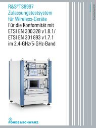
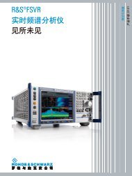
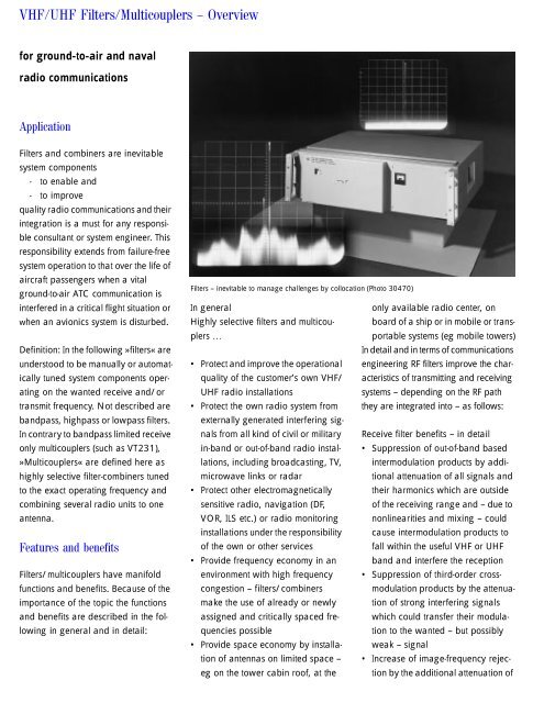
<strong>Filters</strong> – inevitable to manage challenges by collocation (Photo 30470)<br />
In general<br />
only available radio center, on<br />
Highly selective filters and multicouplers<br />
…<br />
portable systems (eg mobile towers)<br />
board of a ship or in mobile or trans-<br />
In detail and in terms of communications<br />
• Protect and improve the operational engineering RF filters improve the characteristics<br />
of transmitting and receiving<br />
quality of the customer’s own <strong>VHF</strong>/<br />
<strong>UHF</strong> radio installations<br />
systems – depending on the RF path<br />
• Protect the own radio system from they are integrated into – as follows:<br />
externally generated interfering signals<br />
from all kind of civil or military Receive filter benefits – in detail<br />
in-band or out-of-band radio installations,<br />
including broadcasting, TV, intermodulation products by addi-<br />
• Suppression of out-of-band based<br />
microwave links or radar<br />
tional attenuation of all signals and<br />
• Protect other electromagnetically their harmonics which are outside<br />
sensitive radio, navigation (DF,<br />
of the receiving range and – due to<br />
VOR, ILS etc.) or radio monitoring nonlinearities and mixing – could<br />
installations under the responsibility cause intermodulation products to<br />
of the own or other services<br />
fall within the useful <strong>VHF</strong> or <strong>UHF</strong><br />
• Provide frequency economy in an band and interfere the reception<br />
environment with high frequency • Suppression of third-order crossmodulation<br />
products by the attenua-<br />
congestion – filters/combiners<br />
make the use of already or newly tion of strong interfering signals<br />
assigned and critically spaced frequencies<br />
possible<br />
tion to the wanted – but possibly<br />
which could transfer their modula-<br />
• Provide space economy by installation<br />
of antennas on limited space – • Increase of image-frequency rejec-<br />
weak – signal<br />
eg on the tower cabin roof, at the tion by the additional attenuation of
signals defined as image frequency<br />
relative to the received frequency<br />
• Increase of intermediate frequency<br />
(IF) rejection by additional attenuation<br />
of interfering signals on one of<br />
the intermediate frequencies<br />
• Prevention of desensitization (reciprocal<br />
mixing) by the attenuation of<br />
strong interfering signals which could<br />
otherwise transfer the noise sidebands<br />
of the receiver oscillator, mixed<br />
onto the interfering signal, to the useful<br />
band, thus reducing sensitivity<br />
• Prevention of blocking by the attenuation<br />
of strong interfering signals<br />
which could reduce the amplitude<br />
of the useful IF signal by overdriving<br />
the mixer stage<br />
Transmit filter benefits – in detail<br />
• Attenuation of broadband transmitter<br />
noise caused by the exciter oscillator<br />
or power amplifiers<br />
• Suppression of spurious emissions,<br />
mainly occurring in the small-signal<br />
stages during frequency conditioning<br />
• Suppression of harmonics, mainly<br />
generated in the power stages<br />
• Attenuation of transmitter (backward)<br />
intermodulation products of<br />
the 3rd or higher order: these are<br />
generated – within a simultaneously<br />
operating system with co-sited transmitters<br />
– by the radiation of transmitter<br />
signals via the antennas into<br />
the output of an other transmitter. In<br />
this case the attenuation of the filter<br />
at the transmission end is effectively<br />
doubled and adds to the antennadecoupling<br />
factors.<br />
Practical effects of improvement<br />
Optimized radio installations using filters<br />
help to achieve the offer following<br />
vital operational benefits:<br />
System engineering note<br />
In addition to the use of filters<br />
described here, the following tools<br />
shall be taken into consideration to<br />
master challenges by collocation:<br />
• Preselector FT 402 (Series 400U<br />
option for RX path)<br />
• TX/RX <strong>Filters</strong> FD/FU/FT 403TR<br />
(Series 400U option for the TX and<br />
RX path; FH capable)<br />
• Antenna management by<br />
– Alternative antenna sites<br />
– Alternative use of existing antennas<br />
• Highly decoupled, eg collinear<br />
antenna types (eg HK 353A)<br />
• Circulators<br />
• Frequency Management<br />
(planning)<br />
are useful for suppression of inband<br />
interferences.<br />
• Bandpass filters<br />
• High or lowpass filters<br />
• Notch filters<br />
• Special interference suppression<br />
devices<br />
are helpful for out-of-band interferences.<br />
Benefits by filters – in sum<br />
No irritation of the operator<br />
No degradation of the receive sensitivity<br />
No irritation of the operator by spurious<br />
reception (phantom signals)<br />
No RF output power reduction of the<br />
transmitter<br />
No radiation of unwanted and interfering<br />
signals<br />
Background<br />
By unwanted response of the receiver carrier<br />
squelch<br />
Also with weak wanted receive signals<br />
Such interferences may be generated by signals<br />
identical with the image frequencies or<br />
the intermediate frequency<br />
Interfering signals entering via the antenna<br />
socket influence the VSWR depending gain<br />
control loop<br />
Radiated TX intermodulation products may<br />
lead to self-jamming of the own receive<br />
system or to irritations of the aircraft pilot
Quick type guide and basic specifications<br />
The following guide helps by comparison to identify the right filter or multicoupler for the actual system requirement. For<br />
additional specifications and ordering information please refer to the type-specific »supplementary information«.<br />
Manually tuned<br />
Type<br />
FU220<br />
FU220Wx<br />
FD220<br />
FD220Wx<br />
FD225<br />
FD225Wx<br />
<strong>Filters</strong> with 1 x<br />
HS9043/9<br />
per port<br />
<strong>Filters</strong> with<br />
1 x<br />
HS9043/0<br />
per port<br />
<strong>Filters</strong>/<br />
<strong>Multicouplers</strong><br />
with 1 or 2 x<br />
HS9043 per<br />
radio port<br />
Frequency<br />
Range<br />
(MHz)<br />
Tuning<br />
RF Input Power<br />
AMc =<br />
AM carrier<br />
100 to manual 200 W AMc<br />
162.025 4) 800 W PEP<br />
300 W FM<br />
225 to<br />
399.975<br />
225 to<br />
399.975<br />
100 to<br />
156.000<br />
225 to<br />
399.975<br />
manual<br />
manual<br />
200 W AMc<br />
800 W PEP<br />
300 W FM<br />
200 W AMc<br />
800 W PEP<br />
300 W FM<br />
3 dB BW<br />
(in % of f o<br />
or in MHz)<br />
≥0.05%<br />
≥0.05%<br />
≥0.05%<br />
Selectivity 1)<br />
20 dB: ≤±0.4%<br />
40 dB: ≤±1.0%<br />
60 dB: ≤±4.0%<br />
20 dB: ≤±0.4%<br />
40 dB: ≤±1.0%<br />
60 dB: ≤±4.0%<br />
20 dB: ≤±0.4%<br />
40 dB: ≤±1.0%<br />
60 dB: ≤±4.0%<br />
Insertion Loss<br />
(filter)<br />
≤2.0 dB<br />
(0 to +40°C)<br />
≤2.5 dB<br />
(−20 to +55°C)<br />
additional 0.5 dB<br />
at<br />
≤108 MHz<br />
manual 50 W AMc ≥0.2% (k3) ≥14 dB: 1% (k3) ≤2.0 dB (k3)<br />
≤0.5 dB (k10)<br />
manual<br />
50 W AMc<br />
100 W FM<br />
see above manual see above see above<br />
≥0.2% (k3) ≥17 dB: 1% (k3) ≤2.0 dB (k3)<br />
≤0.5 dB (k10)<br />
≥0.25% (k5)<br />
1 x HS9043 per port:<br />
see above<br />
2 x HS9043 per port:<br />
<strong>VHF</strong>:<br />
≥22 dB: 1% (k5);<br />
<strong>UHF</strong>:<br />
≥32 dB: 1% (k5)<br />
Remarks,<br />
Multicoupler<br />
Capability:<br />
S = Starpoint<br />
T = T-coupler<br />
N = no<br />
S: Up to 4 radios are<br />
combinable to one<br />
antenna<br />
(FU220W4)<br />
≤2.0 dB S: Up to 4 radios are<br />
combinable to one<br />
antenna<br />
(FD220W4)<br />
≤2 dB T: Up to 8<br />
(FD225W8) or even<br />
more 3) radios are<br />
combinable to one<br />
antenna<br />
see above<br />
≤1.5 dB (k5)<br />
≤1 dB (k10)<br />
S 2)<br />
S 2)<br />
A great variety of<br />
special filter and multicoupler<br />
combinations<br />
– with n radio ports<br />
and<br />
– with 1 or 2 cavity<br />
filters per radio<br />
port<br />
are compilable;<br />
details for projectspecific<br />
solutions on<br />
request
Automatically tuned<br />
Type<br />
Frequency<br />
Range<br />
(MHz)<br />
Tuning<br />
RF Input Power<br />
AMc =<br />
AM carrier<br />
3 dB BW<br />
(in % of f o<br />
or in MHz)<br />
Selectivity 1)<br />
Insertion Loss<br />
(filter)<br />
Remarks,<br />
Multicoupler<br />
Capability:<br />
S = Starpoint<br />
T = T-coupler<br />
N = no<br />
FU214A<br />
100 to auto<br />
162.025 4)<br />
≤4 sec<br />
2 sec typ.<br />
50 W AMc<br />
100 W FM<br />
≤0.5 MHz 20 dB: ≤±2 MHz<br />
35 dB: ≤±5 MHz<br />
40 dB: ≤±7 MHz<br />
≤1.5 dB<br />
(+10 to 40°C)<br />
≤2.0 dB<br />
(−30 to +55°C)<br />
N: Filter with integrated<br />
bypass for<br />
distress channel;<br />
FD213A<br />
225 to<br />
399.975<br />
auto<br />
≤4 sec<br />
2 sec typ.<br />
50 W AMc<br />
100 W FM<br />
≥1 MHz<br />
20 dB: ≤±3 MHz<br />
35 dB: ≤±7 MHz<br />
40 dB: ≤±11 MHz<br />
≤1.5 dB<br />
(+10 to 40°C)<br />
≤2.0 dB<br />
(−30 to +55°C)<br />
N: Filter with integrated<br />
bypass for<br />
distress channel;<br />
FD213A2<br />
225 to<br />
399.975<br />
(2x)<br />
auto<br />
≤4 sec<br />
2 sec typ.<br />
50 W AMc<br />
100 W FM<br />
(per radio)<br />
≥1 MHz<br />
20 dB: ≤±3 MHz<br />
35 dB: ≤±7 MHz<br />
40 dB: ≤±11 MHz<br />
≤1.5 dB<br />
(+10 to 40°C)<br />
≤2.0 dB<br />
(−30 to +55°C)<br />
N: Dual filter for 2<br />
independently operating<br />
<strong>UHF</strong> radios;<br />
with integrated<br />
bypass for <strong>UHF</strong> distress<br />
channel;<br />
FT213A<br />
100 to auto<br />
162.025<br />
and ≤4 sec<br />
225 to 2 sec typ.<br />
399.975 4)<br />
50 W AMc<br />
100 W FM<br />
<strong>VHF</strong>:<br />
≥0.5 MHz<br />
<strong>UHF</strong>:<br />
≥1 MHz<br />
<strong>VHF</strong>:<br />
20 dB: ≤±2 MHz<br />
35 dB: ≤±5 MHz<br />
40 dB: ≤±7 MHz<br />
<strong>UHF</strong>:<br />
20 dB: ≤±3 MHz<br />
35 dB: ≤±7 MHz<br />
40 dB: ≤±11 MHz<br />
≤1.5 dB<br />
(+10 to 40°C)<br />
≤2.0 dB<br />
(−30 to +55°C)<br />
N: Combined <strong>VHF</strong>/<br />
<strong>UHF</strong> filter with integrated<br />
bypass for<br />
<strong>VHF</strong> and <strong>UHF</strong> distress<br />
channels;<br />
FU221<br />
FU221Wx<br />
100 to auto<br />
162.025 4)<br />
≤10 sec<br />
6 sec typ.<br />
200 W AMc<br />
800 W PEP<br />
300 W FM<br />
≥0.05%<br />
20 dB: ≤±0.4%<br />
40 dB: ≤±1.0%<br />
60 dB: ≤±4.0%<br />
≤2.0 dB<br />
(0 to +40°C)<br />
≤2.5 dB<br />
(−20 to +55°C)<br />
Additional<br />
0.5 dB at<br />
≤108 MHz<br />
S: Up to 4 radios are<br />
combinable to one<br />
antenna<br />
(FU 221W4)<br />
FD221<br />
FD221Wx<br />
225 to<br />
399.975<br />
auto<br />
≤10 sec<br />
6 sec typ.<br />
200 W AMc<br />
800 W PEP<br />
300 W FM<br />
≥0.05%<br />
20 dB: ≤±0.4%<br />
40 dB: ≤±1.0%<br />
60 dB: ≤±4.0%<br />
≤2.0 dB S: Up to 4 radios are<br />
combinable to one<br />
antenna<br />
(FD 221W4)<br />
1 Attenuation at x % frequency separation from center frequency f o .<br />
2 HS9043 filters have variable coupling degree (k1 to k10).<br />
3 With lower RF input power.<br />
4 Nominal value is 162.025 MHz, but operation is guaranteed up to<br />
162.975 MHz
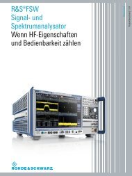
<strong>VHF</strong> <strong>Filters</strong> FU220<br />
<strong>UHF</strong> <strong>Filters</strong> FD220<br />
<strong>VHF</strong> <strong>Multicouplers</strong> FU220W(.)<br />
<strong>UHF</strong> <strong>Multicouplers</strong> FD220W(.)<br />
– Manually tuned<br />
– High RF power<br />
– High selectivity<br />
– 4 ports or less<br />
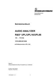
<strong>VHF</strong> Filter FU220 (Photo 33042)<br />
Brief Description<br />
Design and features<br />
The filters FU220 and FD220 are<br />
made up of two coaxial resonators,<br />
fixed coupled to form a compact twosection<br />
filter plug-in. Tuning is performed<br />
manually by altering the length<br />
of the longitudinally adjustable inner<br />
conductors via a gearing common to<br />
both resonators. From the gear unit,<br />
two axles are led outward through the<br />
front panel on which the tuning knobs<br />
for coarse and fine tuning are fixed.<br />
The axles are connected each with a<br />
scale for manual tuning.<br />
A robust and mechanically stiff layout<br />
and the use of temperature-stable<br />
INVAR (iron-nickel alloy) for filter<br />
bodies, spindles and coupling loup in<br />
connection with silver-coating guarantee<br />
the specifications<br />
• throughout the entire temperature<br />
range and<br />
• under 100% duty-cycle high-power<br />
operation.<br />
Multicoupler capability<br />
To form a multicoupler (combining filter)<br />
to operate a number of either<br />
transmitters or receivers via a single<br />
antenna only up to 4 filters can be<br />
combined via a <strong>VHF</strong> or <strong>UHF</strong> 2- or 4-<br />
way combining array for rack integration.<br />
This array consists of a starpoint<br />
and a multistage quarter-wave transformation<br />
line towards the common<br />
antenna ensuring good matching of<br />
the filter inputs to the input impedance<br />
of the antenna over the entire <strong>VHF</strong> or<br />
<strong>UHF</strong> band. The multicouplers are thus<br />
suitable for operation at any frequency<br />
in the band.<br />
Please note:<br />
• Two differing filter models for standalone<br />
(screw-type RF sockets) or<br />
multicoupler use (plug-in type RF<br />
sockets)<br />
• Different filter arrangement in multicouplers<br />
for <strong>VHF</strong> (filters in horizontal<br />
position) or <strong>UHF</strong> (filters in vertical<br />
position: two upper and two<br />
lower units). The reason for this is<br />
the necessary short connection to<br />
the 2- or 4-way combining array.<br />
• Extension models of multicouplers<br />
available, prepared by 100% for a<br />
Application example for 4-port multicoupler<br />
later upgrading to 4 ports maximum.<br />
For such details please refer<br />
to ordering information.
Specifications<br />
Basic specifications<br />
– Frequency range<br />
– RF Power Handling<br />
– Bandwidth<br />
– Selectivity<br />
– Insertion loss<br />
see quick type guide<br />
Additional specifications<br />
Circuit design characteristics Fixed-coupled 2-circuit (resonator) type<br />
Input impedance (radio port) 50 Ω, VSWR:<br />
≤1.6 : 1 (0 to +40°C)<br />
≤2.0 : 1 (−20 to +55°C)<br />
Valid for filters; multicouplers see<br />
below<br />
Output impedance (antenna port) 50 Ω<br />
RF connectors (radio or antenna port) N-type socket<br />
Different specifications for multicouplers<br />
Number of inputs (radio ports) 2 to 4 depending on type and model<br />
Maximum total RF input power 2 to 4 x 200 W AM carrier,<br />
100% mod.<br />
2 to 4 x 300 W FM<br />
Maximum total RF output power<br />
(antenna port)<br />
Insertion loss<br />
FD220W2/W4<br />
FU220W2/W4<br />
Input impedance (radio port)<br />
General data<br />
800 W AM carrier, 100% mod.;<br />
1200 W FM<br />
≤2.5 dB (−20 to +55°C)<br />
≤2.5 dB (0 to +40°C)<br />
≤3.0 dB (−20 to +55°C)<br />
additional 0.5 dB at f ≤108 MHz<br />
50 Ω, VSWR:<br />
≤2.0 : 1 (0 to +40°C)<br />
≤2.5 : 1 (−20 to +55°C)<br />
EMC<br />
MIL-STD-461/462<br />
Environmental testing VG 95332<br />
Storage at low temperature page 22, grade 4 (−55°C)<br />
Storage in dry heat<br />
page 23, grade +75°C<br />
Operating temperature<br />
cold testing<br />
page 3, grade −20°C<br />
dry heat<br />
page 3, grade 7 (+55°C), but with<br />
30% humidity<br />
damp heat<br />
page 5, grade 8 (+40°C),<br />
95% humidity without condensation<br />
Mechanical VG 95332<br />
vibration<br />
page 24, group A (10 to 55 Hz),<br />
grade 2; unit in position of use for the<br />
whole test period of 30 min<br />
Dimensions W x H x D (in mm)<br />
FU220<br />
483 x 220 x 560 (seated depth)<br />
FD220<br />
483 x 220 x 500 (seated depth)<br />
FU/FD220W2 (.02)<br />
550 x 445 x 592 (rack requirement)<br />
FU/FD220W4 (.02)<br />
550 x 890 x 592 (rack requirement)<br />
Weight<br />
FU/FD220<br />
≈30 kg<br />
FU/FD220W2 (.02)<br />
≈65 kg<br />
FU/FD220W4 (.02)<br />
≈130 kg<br />
Note: Specifications refer to filters and multicouplers, if not stated otherwise,<br />
and to nominal RF terminations (50 Ω).<br />
Ordering Information<br />
<strong>UHF</strong> Filter FD220 0636.9010.02<br />
Standard filter 1)<br />
Spare model for multicoupler W2 FD220 0636.9010.03<br />
Spare/extension model for upper<br />
two filters of W4 (.02/.03/.04)<br />
Spare model for W4 (.12) 2)3)<br />
Spare/extension model FD220 0636.9010.04<br />
for lower two filters of W4 (.02/.03/.04) 2)3)<br />
<strong>UHF</strong> 2-Port Multicoupler FD220W2 0643.2017.02<br />
Standard type, 19" 10 HU 3)<br />
<strong>UHF</strong> 4-Port Multicoupler FD220W4 0643.4010.02<br />
Standard type, 19" 20 HU 4)<br />
Special model 5) FD220W4 0643.4010.12<br />
<strong>UHF</strong> 2-Port Multicoupler FD220W4 0643.4010.03<br />
Special model, 19" 20 HU,<br />
extendable to 4 ports by FD220 (.04) 6)<br />
<strong>UHF</strong> 3-Port Multicoupler FD220W4 0643.4010.04<br />
Special model, 19" 20 HU,<br />
extendable to 4 ports by FD 220 (.04) 6)<br />
<strong>VHF</strong> Filter FU220 0635.0019.02<br />
Standard filter 1)<br />
Spare model for multicouplers<br />
W2 or W4 FU220 0635.0019.03<br />
Extension model for W4 7)<br />
<strong>VHF</strong> 2-Port Multicoupler FU220W2 0643.3013.02<br />
Standard type, 19" 10 HU<br />
<strong>VHF</strong> 4-Port Multicoupler FU220W4 0643.5016.02<br />
Standard type, 19" 20 HU 7)<br />
<strong>VHF</strong> 2-Port Multicoupler FU220W4 0643.5016.03<br />
Special model, 19" 20 HU,<br />
extendable to 4 ports 6)<br />
<strong>VHF</strong> 3-Port Multicoupler FU220W4 0643.5016.04<br />
Special model, 19" 20 HU,<br />
extendable to 4 ports 6)<br />
For multicoupler configuration examples please refer to page 177: the photo<br />
shows automatically tuned 4-port multicouplers, but manually tuned<br />
FD220W4 or FU220W4 look similar.<br />
1 Horizontal 19" 5 HU rack plug-in with standard (screwed)<br />
RF connectors, for stand-alone filter (not multicoupler) use.<br />
2 Vertical 1 / 2 19" 10 HU plug-in with plug-in type RF connectors for<br />
automatic connection with the multicoupler combining array.<br />
3 FD220W2 (.02) is consisting of two <strong>UHF</strong> <strong>Filters</strong> FD220 (.03) and<br />
one <strong>UHF</strong> 2-way combining array.<br />
4 FD220W4 (.02) is consisting of two upper filter plug-ins<br />
FD220 (.03) side-by-side, two lower filter plug-ins FD220 (.04) sideby-side<br />
and one <strong>UHF</strong> 4-way combining array. For logistics advantage:<br />
see Note 5.<br />
5 FD221W4 (.12) can be used as special alternative to model 02: it<br />
includes 4 identical <strong>Filters</strong> FD221 (.03) – putting up with 2 headstanding<br />
filters in respect of the panel description.<br />
6 Delivered with 50 Ω terminations for empty extension port(s).<br />
7 FU220W4 (.02) is consisting of four <strong>VHF</strong> <strong>Filters</strong> FU220 (.03) and<br />
one <strong>VHF</strong> 4-way combining array.
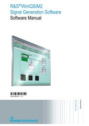
<strong>UHF</strong> <strong>Filters</strong> FD225<br />
<strong>UHF</strong> <strong>Multicouplers</strong> FD225W(.)<br />
– Manually tuned<br />
– High RF power<br />
– High selectivity<br />
– Up to 8 or more ports<br />
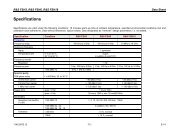
<strong>UHF</strong> Filter FD225 (Photo 37721)<br />
Design and features<br />
The design of the FD225 corresponds<br />
in principle to that of the 2-circuit resonator<br />
filter type FD220, where the tuning<br />
is performed by alternating the<br />
length of the inner conductors, but with<br />
the essential T-coupler add-on, integrated<br />
at the left end of the 19" 5 HU<br />
filter plug-in. For the design and features<br />
of the basic 2-circuit filter details<br />
please refer to FD220.<br />
Multicoupler capability<br />
The integrated T-coupler device enables<br />
the coupling of 8 high-power (or<br />
even more medium power) transmitters<br />
to one common antenna where<br />
one single TX antenna is. More than 8<br />
transmitters can be combined for<br />
extremely concentrated applications<br />
taking into account engineering<br />
aspects like additional insertion loss<br />
per channel, maximum output powerhandling,<br />
standby concept or rack<br />
height.<br />
Designed in low-loss strip-line technology<br />
the T-coupler is a circuit-shaped<br />
50 line device similar to a potentiome-<br />
ter, which enables the manual variation<br />
of the line length by move of the<br />
center arm. Thus impedances are<br />
transformed is such a way that the<br />
energy flow of T-coupled transmitters is<br />
always directed towards the antenna<br />
with an excellent VSWR over the<br />
entire <strong>UHF</strong> frequency range. By the<br />
use of appropriate dielectrical material<br />
a wide termination variation is<br />
achieved, while the dimensions are<br />
still constant and small.<br />
Exact adjustment of each filter output<br />
to the antenna is performed manually<br />
from the filter front panel by tuning the<br />
T-coupler to minimum VSWR (shown<br />
on the TX-integrated indication). For<br />
the electrical multicoupler configuration<br />
RF cables of the filters FD225 are<br />
required only (in addition to a short<br />
circuit termination for the T-coupler of<br />
the first filter). A complete <strong>UHF</strong> 8-port<br />
Multicoupler FD225W8 eg consists of<br />
8 filters FD225, a rack mounting kit<br />
(rugged mechanical support structure<br />
to guarantee the rack statics, matching<br />
the dimensions of the 19" rack as contracted<br />
under an extra item), a RF<br />
cable set, accessories, compilation<br />
and a protocolled subsystem test.<br />
<strong>UHF</strong> 7-port Multicoupler FD225W7<br />
(Photo 37808)
Specifications<br />
Basic specifications<br />
– Frequency range<br />
– RF Power Handling<br />
– Bandwidth<br />
– Selectivity<br />
– Insertion loss<br />
see quick type guide<br />
Additional specifications<br />
Circuit design characteristics<br />
Input impedance (radio port)<br />
Output impedance (antenna port)<br />
RF connectors<br />
radio port<br />
T-coupler ports (for next T-coupler<br />
or antenna)<br />
Fixed-coupled 2-circuit (resonator)<br />
type with integrated T-coupler<br />
50 Ω, VSWR:<br />
≤1.6 : 1 (0 to +40°C)<br />
≤2.0 : 1 (−20 to +55°C)<br />
Valid for filters; multicouplers see<br />
below<br />
50 Ω<br />
N-type socket<br />
7/16 type sockets<br />
General data<br />
EMC<br />
MIL-STD-461/462<br />
Environmental testing VG 95332<br />
Storage at low temperature page 22, grade 4 (−55°C)<br />
Storage in dry heat<br />
page 23, grade +75°C<br />
Operating temperature<br />
cold testing<br />
page 3, grade 6 (−30°C)<br />
dry heat<br />
page 3, grade 7 (+55°C), but with<br />
30% humidity<br />
damp heat<br />
page 5, grade 8 (+40°C), 95% humidity<br />
without condensation<br />
Mechanical VG 95332<br />
vibration<br />
page 24, group A (10 to 55 Hz),<br />
grade 2; 30 min total testing time in<br />
operational position with unit switched<br />
off, followed by functional testing<br />
Dimensions (FD225) W x H x D 483 mm x 220 mm x 500 mm<br />
(seated depth), 19" 5 HU plug-in<br />
Weight (FD225)<br />
≈30 kg<br />
Note: Specifications refer to filters and multicouplers, if not stated otherwise,<br />
and nominal RF terminations (50 Ω).<br />
Ordering Information<br />
Different specifications for multicouplers<br />
Number of inputs (radio ports)<br />
Maximum total RF output power<br />
(antenna port)<br />
Insertion loss<br />
Filter loss<br />
Additional loss by T-coupler<br />
Input impedance (radio port)<br />
2 to 8 (or >8) depending on summarized<br />
power at the antenna port. Easy<br />
expansion capability eg from a 6-port<br />
to a 8-port multicoupler due to the<br />
modular and broadband design<br />
1600 W FM<br />
≤2.0 dB<br />
≤0.1 dB per channel<br />
50 Ω, VSWR:<br />
≤2.0 : 1 (0 to +40°C)<br />
≤2.5 : 1 (−20 to +55°C)<br />
<strong>UHF</strong> Filter<br />
Spare/extension model<br />
for multicouplers FD225 6004.4009.02<br />
<strong>UHF</strong> 8-port Multicoupler<br />
Standard type FD225W8 6004.6301.02<br />
<strong>UHF</strong> n-port Multicoupler<br />
Standard type with n ports<br />
on request<br />
FD 225W(.)<br />
1)<br />
1 For n=2, 3 and 4 compare also the starpoint multicouplers<br />
FD220W2 and W4.
<strong>VHF</strong> and <strong>UHF</strong> Filter Combinations<br />
<strong>VHF</strong> and <strong>UHF</strong> <strong>Multicouplers</strong><br />
with HS9043 Cavities<br />
– Manually tuned<br />
– Medium RF power<br />
– Medium selectivity<br />
Design and features<br />
The cavity filters HS9043 are proven<br />
»working horses« and used already<br />
over decades of years with unbroken<br />
actuality. Their<br />
Cavity Filter HS9043<br />
(Photo 19042)<br />
• excellent mechanical precision<br />
• versatility in use for multi-port filters<br />
or multicouplers<br />
• reasonable size and<br />
• good price/performance ratio<br />
Filter or multicoupler<br />
configuration with 3<br />
cavity filters HS9043<br />
(Photo 21041)<br />
make these filters very attractive. They<br />
are applied to single-channel systems<br />
where both, medium power handling<br />
and medium selectivity, are sufficient.<br />
For more stringent requirements, however,<br />
the filters FD/FU220 or FD225<br />
are unbeatable to overcome co-site<br />
conditions requiring highest selectivity<br />
and/or in connection with high RF<br />
power rating.<br />
There are 2 basic types: the <strong>VHF</strong> Filter<br />
HS9043/9… and the <strong>UHF</strong> Filter<br />
HS9043/0… which are equal in<br />
design and function principle, they<br />
only differ in specifications and dimensions.<br />
The expression »HS9043« is<br />
standing for both types.<br />
The HS9043 is cylinder-shaped and<br />
designed as coaxial resonant-line circuit<br />
with an inner and outer conductor.<br />
Between the free end of the inner conductor<br />
and the outer conductor is – in<br />
axle direction – a variable capacitance<br />
which is designed like a coaxial tubular<br />
capacitor with contact springs to the<br />
outer conductor. By tuning the spindle<br />
with the scale knob one can vary the<br />
sunken depth of the capacitor along its<br />
longitudinal axis and adjust to the<br />
wanted resonance frequency. The input<br />
and output coupling is made with variable<br />
coupling loops which can be rotated<br />
separately to vary the coupling degree<br />
(k) and thus the selectivity of the filter.<br />
Special filter and multicoupler<br />
capability<br />
The HS9043 can be configurated to<br />
• special filter types, eg<br />
– with 3-ports for 3 radios and<br />
3 antennas or<br />
– with 2 filters per port (double-section<br />
filter) to increase the selectivity<br />
• starpoint-type multicouplers.<br />
The corresponding number of cavity filters<br />
HS9043 is assembled together with<br />
a mechanical slide-in unit, special coaxial<br />
2-, 4- or 8-way starpoints, RF cables,<br />
transformation stages etc. to form a compact<br />
19" plug-in for rack integration.
Specifications<br />
Basic specifications<br />
– Frequency range<br />
– RF Power Handling<br />
– Bandwidth<br />
– Selectivity<br />
– Insertion loss<br />
see introductory »Quick type guide«<br />
Additional specifications<br />
Circuit design characteristics Variable-coupled cavity resonator type<br />
filters<br />
Input and output coupling degree manually settable for both: k ≤10<br />
Input impedance (radio port) 50 Ω, VSWR:<br />
of a single-section filter ≤1.1 : 1 (f o )<br />
≤2.0 : 1 (f o ±0.1% at coupling degree<br />
k5), valid for filters; multicouplers see<br />
below<br />
Input impedance (radio port) 50 Ω, VSWR:<br />
of a double-section filter ≤1.2 : 1 (f o )<br />
≤1.5 : 1 (f o ±100 kHz)<br />
Output impedance (antenna port) 50 Ω<br />
RF connectors (radio or antenna port) N-type socket<br />
Effect of temperature<br />
≤3 kHz/°C<br />
Maximum ambient temperature +55°C<br />
Different specifications for multicouplers<br />
Number of inputs (radio ports) Up to 8 depending on type and model<br />
Total RF input power Up to 8 x 50 W AM carrier, 100%<br />
mod. (<strong>VHF</strong>)<br />
Up to 8 x 30 W AM carrier, 100%<br />
mod. (<strong>UHF</strong>) 1)<br />
Insertion loss<br />
Depending on project-specific filter<br />
settings<br />
General data<br />
Max. operating temperature +55°C<br />
Dimensions W x H x D (in mm)<br />
HS9043/9 (<strong>VHF</strong>)<br />
HS9043/0 (<strong>UHF</strong>)<br />
<strong>VHF</strong> Filter or multicoupler with<br />
3 x HS9043/9, 19" 4 HU rack<br />
plug-in 483 x 177 x 446<br />
<strong>UHF</strong> Filter or multicoupler with<br />
3 x HS9043/0, 19" 4 HU rack<br />
plug-in 483 x 177 x 446<br />
Filter/multicoupler configurations<br />
with n x HS9043<br />
Weight<br />
HS9043/9 (<strong>VHF</strong>)<br />
HS9043/0 (<strong>UHF</strong>)<br />
148 x 446 (diameter x length)<br />
148 x 290 (diameter x length)<br />
n = 4 to 6: 19" 8 HU<br />
n = 7 to 9: 19" 12 HU<br />
≈7 kg<br />
≈7 kg<br />
Note: Specifications refer to filters and multicouplers, if not stated otherwise,<br />
and to nominal RF terminations (50 Ω).<br />
Ordering Information<br />
<strong>VHF</strong> Cavity Type Filter HS9043/9 0138.5746.02<br />
Cylinder type filter<br />
<strong>UHF</strong> Cavity Type Filter HS9043/0 0156.5738.02<br />
Cylinder type filter<br />
<strong>VHF</strong> Filter and Combiners, configuration examples<br />
19" plug-in assemblies with several ports 2)<br />
<strong>VHF</strong> 1-Port Filter FU432W1 0713.7305.02<br />
1 x HS9043/9<br />
<strong>VHF</strong> 2-Port Filter FU256 0682.7016.02<br />
1 x HS9043/9 per port<br />
<strong>VHF</strong> 2-Port Filter FU255 0679.8815.02<br />
2 x HS9043/9 per port<br />
<strong>VHF</strong> 3-Port Filter FU263 6009.3000.xx<br />
1 x HS9043/9 per port RX-Filter = Var. 02<br />
TX-Filter = Var. 03<br />
<strong>VHF</strong> 3-Port Filter FU265 6009.3100.xx<br />
2 x HS9043/9 per port RX-Filter = Var. 02<br />
TX-Filter = Var. 03<br />
<strong>VHF</strong> 2-Port Multicoupler FU432W2 0712.4502.02<br />
1 x HS9043/9 per port<br />
<strong>VHF</strong> 3-Port Multicoupler FU432W4 0712.4502.03<br />
1 x HS9043/9 per port<br />
<strong>VHF</strong> 4-Port Multicoupler FU432W4 0712.4502.04<br />
1 x HS9043/9 per port<br />
<strong>VHF</strong> 5-Port Multicoupler FU432W8 0712.4502.05<br />
1 x HS9043/9 per port<br />
<strong>VHF</strong> 6-Port Multicoupler FU432W8 0712.4502.06<br />
1 x HS9043/9 per port<br />
<strong>VHF</strong> 7-Port Multicoupler FU432W8 0712.4502.07<br />
1 x HS9043/9 per port<br />
<strong>VHF</strong> 8-Port Multicoupler FU432W8 0712.4502.08<br />
1 x HS9043/9 per port<br />
<strong>UHF</strong> Filter and Combiners, configuration examples<br />
<strong>UHF</strong> 1-Port Filter FD256 0682.7216.11<br />
1 x HS9043/0<br />
<strong>UHF</strong> 2-Port Filter FD256 0682.7216.02<br />
1 x HS9043/0 per port<br />
<strong>UHF</strong> 3-Port Filter FD256 0682.7216.13<br />
1 x HS9043/0 per port<br />
<strong>UHF</strong> 2-Port Filter FD255 0679.8515.02<br />
2x HS9043/0 per port<br />
<strong>UHF</strong> 2-Port Multicoupler FD432W4 0745.6504.02<br />
1 x HS9043/0 per port<br />
<strong>UHF</strong> 3-Port Multicoupler FD432W4 0745.6504.03<br />
1 x HS9043/0 per port<br />
<strong>UHF</strong> 4-Port Multicoupler FD432W4 0745.6504.04<br />
1 x HS9043/0 per port<br />
etc. further types TBD<br />
1 The maximum power-handling capacity is a function of the coupling<br />
degree. The values refer to Series 200 transmitters and low filter coupling<br />
degrees (ie high selectivity).<br />
2 »Port« refers to radio ports.
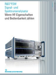
<strong>VHF</strong> <strong>Filters</strong> FU214A, <strong>UHF</strong> <strong>Filters</strong> FD213A<br />
<strong>UHF</strong> Filter (dual type) FD213A2, <strong>VHF</strong>/<strong>UHF</strong> Filter FT213A<br />
– Automatically tuned<br />
– Medium RF power<br />
– Medium selectivity<br />
– Bypass for distress<br />
frequencies<br />
– Stationary and mobile use<br />
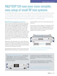
<strong>VHF</strong>/<strong>UHF</strong> Automatic Filter FT213A;<br />
Note that the standard model 05 is fitted with 19" rack mount devices (instead of cabinet)<br />
(Photo 30474-1)<br />
Design and features<br />
This filter series has outstanding features<br />
such as<br />
• Compact 19" 3 HU design<br />
• Combined <strong>VHF</strong>/<strong>UHF</strong> type available<br />
• Integrated bypass for receiving the<br />
<strong>VHF</strong>, <strong>UHF</strong> or both distress frequencies<br />
A combined <strong>VHF</strong>/<strong>UHF</strong> Filter FT213A<br />
eg includes per frequency range two<br />
capacitively tuned coaxial resonators<br />
to form a two-section filter for the operating<br />
frequency. Tuning is carried out<br />
by means of a common 1) axle which<br />
is driven and controlled by a<br />
microprocessor-controlled stepping<br />
motor by way of a gearing. Following<br />
a frequency change input from the<br />
radio, the filter tuning axle is first<br />
driven to the normal start (HOME)<br />
position. It is then moved to an angular<br />
position corresponding to the new<br />
frequency. The tuning is supported by<br />
a sophisticated and optically assisted<br />
motor control. If the frequency change<br />
is less than 100 kHz, retuning does<br />
not take place. The emission of RF<br />
power during the automatic tuning<br />
process is prohibited.<br />
From the gear unit, an additional axle<br />
is led outward on which a manual tuning<br />
knob can be fixed in the event of<br />
automatic tuning failure, supported by<br />
the integrated scales and tuning control<br />
meter.<br />
The robust design and the use of<br />
selected temperature-stable materials<br />
and low-loss (silver-coated) surfaces<br />
guarantee the specifications<br />
• throughout the entire temperature<br />
range and<br />
• under 100% duty-cycle operation.<br />
The control cable between filter and<br />
radio unit provides the operating DC<br />
voltage as well as necessary frequency<br />
and other control information.<br />
Bypass and mobile benefits<br />
The 121.5 MHz bypass or 243 MHz<br />
bypass (<strong>VHF</strong> or <strong>UHF</strong> guard receiver<br />
bypasses) bridges the guard frequency<br />
across to the receiver by active<br />
extraction. During transmit operation<br />
the bypass is disabled electronically<br />
by means of control information from<br />
the radio. Thus distress channel reception<br />
is possible automatically without<br />
any manipulations.<br />
1 Common for both, the 2 resonators per frequency<br />
band and for <strong>VHF</strong> and <strong>UHF</strong>.
Specifications<br />
Basic specifications<br />
– Frequency range<br />
– RF Power Handling<br />
– Bandwidth<br />
– Selectivity<br />
– Insertion loss<br />
see introductory »Quick type guide«<br />
Additional specifications<br />
Circuit design characteristics<br />
Input impedance (radio port)<br />
Output impedance (antenna port)<br />
RF connectors<br />
Tuning control<br />
Interface<br />
Code<br />
Start<br />
Power supply<br />
Interface<br />
Voltage<br />
Current (filter)<br />
during tuning<br />
quiescent current<br />
Fixed-coupled 2-circuit (resonator) type<br />
50 Ω, VSWR:<br />
≤1.6 : 1 (+10 to +40°C)<br />
≤2.0 : 1 (−30 to +55°C)<br />
Valid for filters; multicouplers see<br />
below<br />
50 Ω<br />
N-type sockets<br />
control from the radio via the optional<br />
Series 400U Filter/PA Interface<br />
GI414U or Series 200 multi-channel<br />
radios<br />
BCD, TTL positive logic<br />
automatic start by change of BCD<br />
information<br />
DC supply from radio via GI414U<br />
(see above)<br />
28 (+2/−6) V DC , negative to ground<br />
≤2.0 A<br />
≤0.7 A<br />
Bypass filter characteristics and mutual influences<br />
Insertion loss<br />
±1 dB<br />
Additional attenuation of bypass<br />
filter by main filter<br />
(with frequencies close together)<br />
Additional attenuation of main<br />
filter by bypass filter<br />
(with frequencies close together)<br />
Attenuation in stop band<br />
at ≥±8 MHz from 243.0 MHz<br />
at ≥±4 MHz from 121.5MHz<br />
Isolation<br />
≤10 dB for worst cases (details on<br />
request)<br />
≤10 dB for worst cases (details on<br />
request)<br />
>30 dB<br />
>30 dB<br />
>50 dB<br />
General data<br />
EMC<br />
MIL-STD-461/462<br />
Environmental testing VG 95332<br />
Storage at low temperature page 22, grade 4 (−55°C)<br />
Storage in dry heat<br />
page 23, grade +75°C<br />
Operating temperature<br />
cold testing<br />
page 3, grade −20°C<br />
dry heat<br />
page 3, grade 7 (+55°C), but with<br />
30% humidity<br />
damp heat<br />
page 5, grade 8 (+40°C),<br />
95% humidity without condensation<br />
Mechanical VG 95332<br />
vibration<br />
page 24, group A (10 to 55 Hz),<br />
grade 2; unit in position of use for the<br />
whole test period of 30 min<br />
Dimensions W x H x D (in mm)<br />
for standard models (19" 3 HU) 485 x 132 x 450 (seated depth)<br />
for shockmount models 485 x 200 x 450<br />
Weight for standard models 05<br />
FT213A<br />
≈18 kg<br />
FD213A<br />
≈11 kg<br />
FD213A2<br />
≈18 kg<br />
FU214A<br />
≈15 kg<br />
Weight for shockmount models,<br />
in addition<br />
≈4.5 kg<br />
Note: Specifications refer to filters and multicouplers, if not stated otherwise,<br />
and to nominal RF terminations (50 Ω).<br />
Ordering information<br />
<strong>UHF</strong> Filter FD213A 0637.4311.05<br />
<strong>UHF</strong> Filter (2 x <strong>UHF</strong>) FD213A2 0652.5815.05<br />
<strong>VHF</strong> Filter FU214A 0637.4611.05<br />
<strong>VHF</strong>/<strong>UHF</strong> Filter FT213A 0637.4011.05<br />
Standard models for 19" rack<br />
installation<br />
Control Cable FU214Z1 0637.4811.09<br />
2 m with 37-pin D-SUB and<br />
MIL connectors
<strong>VHF</strong> <strong>Filters</strong> FU221<br />
<strong>UHF</strong> <strong>Filters</strong> FD221<br />
<strong>VHF</strong> <strong>Multicouplers</strong> FU221W(.)<br />
<strong>UHF</strong> <strong>Multicouplers</strong> FD221W(.)<br />
– Automatically tuned<br />
– High RF power<br />
– High selectivity<br />
– 4 ports or less<br />
<strong>VHF</strong> Filter FU221 (Photo 33044)<br />
Design and features<br />
The <strong>Filters</strong> FU221 and FD221 are<br />
made up of two coaxial resonators,<br />
fixed coupled to form a compact twosection<br />
filter plug-in. Tuning is performed<br />
manually by altering the length<br />
of the longitudinally adjustable inner<br />
conductors via a gearing common to<br />
both resonators.<br />
The gear is driven by a microprocessor-controlled<br />
stepping motor. Following<br />
a frequency change input from the<br />
radio, the inner conductors of the cavity<br />
resonators are first driven to their<br />
start (HOME) position in mechanic<br />
mid-position. Subsequently, the automatic<br />
tuning is continued by counting<br />
the frequency-specific definite angle of<br />
rotation of the stepping motor which is<br />
supported by a sophisticated and optically<br />
assisted motor control and electronically<br />
stored frequency characteristic<br />
and built-in tests. Two light barriers<br />
prevent the filters from moving<br />
against the two stops. From the gear<br />
unit, an additional axle is led outward<br />
on which a manual tuning knob can<br />
be fixed in the event of automatic tuning<br />
failure.<br />
A robust and mechanically stiff layout<br />
and the use of temperature-stable<br />
INVAR (iron-nickel alloy) for filter<br />
bodies, spindles and coupling loup in<br />
connection with silver-coating guarantee<br />
the specifications<br />
• throughout the entire temperature<br />
range and<br />
• under 100% duty-cycle high-power<br />
operation.<br />
The control cable between filter and<br />
the radio unit provides the operating<br />
DC voltage as well as necessary frequency<br />
and other control information.
Multicoupler capability<br />
To form a multicoupler (combining filter)<br />
to operate a number of either<br />
transmitters or receivers via a single<br />
antenna only up to 4 filters can be<br />
combined via a <strong>VHF</strong> or <strong>UHF</strong> 2- or 4-<br />
way combining array for rack integration.<br />
This array consists of a starpoint<br />
and a multistage quarter-wave transformation<br />
line towards the common<br />
antenna ensuring good matching of<br />
the filter inputs to the input impedance<br />
of the antenna over the entire <strong>VHF</strong> or<br />
<strong>UHF</strong> band. The multicouplers are thus<br />
suitable for operation at any frequency<br />
in the band.<br />
Please note:<br />
• Two differing filter models for standalone<br />
(screw-type RF sockets) or<br />
multicoupler use (plug-in type RF<br />
sockets)<br />
• Different filter arrangement in multicouplers<br />
for <strong>VHF</strong> (filters in horizontal<br />
position) or <strong>UHF</strong> (filters in vertical<br />
position: two upper and two<br />
lower units). The reason for this is<br />
the necessary short connection to<br />
the 2- or 4-way combining array.<br />
• Extension models of multicouplers<br />
available, prepared by 100% for a<br />
later upgrading to 4 ports maximum.<br />
For such details please refer<br />
to ordering information.<br />
<strong>VHF</strong>/<strong>UHF</strong> radio station with Series 400 multichannel transmitters and 4-port <strong>Multicouplers</strong> FU221W4<br />
(<strong>VHF</strong>, right) and FD221W4 (<strong>UHF</strong>, left) (Photo 34072)
Specifications<br />
Basic specifications<br />
– Frequency range<br />
– RF Power Handling<br />
– Bandwidth<br />
– Selectivity<br />
–Insertion loss<br />
see introductory »Quick type guide«<br />
Additional specifications<br />
Circuit design characteristics Fixed-coupled 2-circuit (resonator) type<br />
Input impedance (radio port) 50 Ω, VSWR:<br />
≤1.6 : 1 (0 to +40°C)<br />
≤2.0 : 1 (−20 to +55°C)<br />
Valid for filters; multicouplers see below<br />
Output impedance (antenna port) 50 Ω<br />
RF connectors (radio or antenna port) N-type<br />
Tuning control<br />
Interface<br />
control from the radio via the optional<br />
Series 400U Filter/PA Interface GI414U<br />
or Series 200 multichannel radios<br />
Code<br />
Start<br />
Power supply<br />
Interface<br />
Voltage<br />
Current (filter)<br />
during tuning<br />
quiescent current<br />
BCD, TTL positive logic<br />
automatic start by change of BCD<br />
information<br />
DC supply from radio via GI414U<br />
(see above)<br />
28 (+2/−6) V DC , negative to ground<br />
≤2.0 A<br />
≤0.25 A<br />
Different specifications for multicouplers<br />
Number of inputs (radio ports) 2 to 4 depending on type and model<br />
Maximum total RF input power 2 to 4⋅ 200 W AM carrier, 100% mod.<br />
2 to 4 ⋅ 300 W FM<br />
Maximum total RF output power<br />
(antenna port)<br />
Insertion loss<br />
FD221W2/W4<br />
FU221W2/W4<br />
Input impedance (radio port)<br />
General data<br />
Specifications refer to filters and multicouplers,<br />
if not stated otherwise, and<br />
to nominal RF terminations (50 Ω).<br />
800 W AM carrier, 100% mod.,<br />
1200 W FM<br />
≤2.5 dB (−20 to +55°C)<br />
≤2.5 dB (0 to +40°C)<br />
≤3.0 dB (−20 to +55°C)<br />
additional 0.5 dB at f ≤108 MHz<br />
50 Ω, VSWR:<br />
≤2.0 : 1 (0 to +40°C)<br />
≤2.5 : 1 (−20 to +55°C)<br />
Ordering Information<br />
<strong>UHF</strong> Filter FD221 0633.8012.02<br />
Standard filter 1)<br />
Spare model for multicoupler W2 FD221 0633.8012.03<br />
Spare/extension model for upper<br />
two filters of W4 (.02/.03/.04)<br />
Spare model for W4 (.12) 2)3)<br />
Spare/extension model FD221 0633.8012.04<br />
for lower two filters of W4 (.02/.03/.04) 2)3)<br />
<strong>UHF</strong> 2-Port Multicoupler FD221W2 0643.2517.02<br />
Standard type, 19" 10 HU 3)<br />
<strong>UHF</strong> 4-Port Multicoupler FD221W4 0643.4510.02<br />
Standard type, 19" 20 HU 4)<br />
Special model 5) FD221W4 0643.4510.12<br />
<strong>UHF</strong> 2-Port Multicoupler FD221W4 0643.4510.03<br />
Special model, 19" 20 HU,<br />
extendable to 4 ports by FD220 (.04) 6)<br />
<strong>UHF</strong> 3-Port Multicoupler FD221W4 0643.4510.04<br />
Special model, 19" 20 HU,<br />
extendable to 4 ports by FD 220 (.04) 6)<br />
<strong>VHF</strong> Filter FU221 0643.6012.02<br />
Standard filter 1)<br />
Spare model for W2 or W4 FU221 0643.6012.03<br />
Extension model for W4 2)<br />
<strong>VHF</strong> 2-Port Multicoupler FU221W2 0643.3513.02<br />
Standard type, 19" 10 HU<br />
<strong>VHF</strong> 4-Port Multicoupler FU221W4 0643.5516.02<br />
Standard type, 19" 20 HU 7)<br />
<strong>VHF</strong> 2-Port Multicoupler FU221W4 0643.5516.03<br />
Special model, 19" 20 HU,<br />
extendable to 4 ports 6)<br />
<strong>VHF</strong> 3-Port Multicoupler FU221W4 0643.5516.04<br />
Special model, 19" 20 HU,<br />
extendable to 4 ports 6)<br />
Control Cable ZT297 0637.3838.xx<br />
2 m xx = 02<br />
5 m xx = 05<br />
10 m xx = 10<br />
EMC<br />
MIL-STD-461/462<br />
Environmental testing VG 95332<br />
Storage at low temperature page 22, grade 4 (−55°C)<br />
Storage in dry heat<br />
page 23, grade +75°C<br />
Operating temperature<br />
cold testing<br />
page 3, grade −20°C<br />
dry heat<br />
page 3, grade 7 (+55°C), but with<br />
30% humidity<br />
damp heat<br />
page 5, grade 8 (+40°C),<br />
95% humidity without condensation<br />
Mechanical VG 95332<br />
vibration<br />
page 24, group A (10 to 55 Hz),<br />
grade 2; unit in position of use for the<br />
whole test period of 30 min<br />
Dimensions W x H x D (in mm)<br />
FU221<br />
483 x 220 x 560 (seated depth)<br />
FD221<br />
483 x 220 x 500 (seated depth)<br />
FU/FD221W2 (.02)<br />
550 x 445 x 592 (rack requirement)<br />
FU/FD221W4 (.02)<br />
550 x 890 x 592 (rack requirement)<br />
Weight<br />
FU/FD221<br />
≈30 kg<br />
FU/FD221W2 (.02)<br />
≈65 kg<br />
FU/FD221W4 (.02)<br />
≈130 kg<br />
1 Horizontal 19" 5 HU rack plug-in with standard (screwed)<br />
RF connectors, for stand-alone filter (not multicoupler) use.<br />
2 Vertical 1 / 2 19" 10 HU plug-in with plug-in type RF connectors for<br />
automatic connection with the multicoupler combining array.<br />
3 FD221W2 (.02) is consisting of two <strong>UHF</strong> <strong>Filters</strong> FD221 (.03) and<br />
one <strong>UHF</strong> 2-way combining array.<br />
4 FD221W4 (.02) is consisting of two upper filter plug-ins FD221<br />
(.03) side-by-side, two lower filter plug-ins FD221 (.04) side-by-side<br />
and one <strong>UHF</strong> 4-way combining array. For logistics advantage: see<br />
Note 5.<br />
5 FD221W4 (.12) can be used as special alternative to model 02: it<br />
includes 4 identical <strong>Filters</strong> FD221 (.03) – putting up with 2 headstanding<br />
filters in respect of the panel description.<br />
6 Delivered with 50 Ω terminations for empty extension port(s).<br />
7 FU221W4 (.02) is consisting of four <strong>VHF</strong> <strong>Filters</strong> FU221 (.03) and<br />
one <strong>VHF</strong> 4-way combining array.