Download article as PDF (0.5 MB) - Rohde & Schwarz Singapore
Download article as PDF (0.5 MB) - Rohde & Schwarz Singapore
Download article as PDF (0.5 MB) - Rohde & Schwarz Singapore

Create successful ePaper yourself
Turn your PDF publications into a flip-book with our unique Google optimized e-Paper software.
GENERAL PURPOSE<br />
Test systems<br />
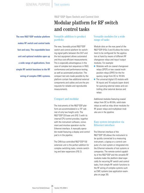
R&S ® OSP Open Switch and Control Unit<br />
Modular platform for RF switch<br />
and control t<strong>as</strong>ks<br />
The new R&S ® OSP modular platform<br />
makes RF switch and control t<strong>as</strong>ks<br />
f<strong>as</strong>t and e<strong>as</strong>y. The expandable b<strong>as</strong>e<br />
unit and optional modules open up<br />
a wide range of applications, from<br />
simple RF switch functions to the RF<br />
wiring of complex EMC systems.<br />
Versatile addition to product<br />
portfolio<br />
The new, favorably priced R&S ® OSP<br />
switch and control platform for switching<br />
signal paths between the DUT and<br />
the test equipment allows automated<br />
and thus cost-efficient me<strong>as</strong>urements.<br />
This is especially advantageous in the<br />
c<strong>as</strong>e of complex test sequences in R&D,<br />
conformance and performance testing<br />
<strong>as</strong> well <strong>as</strong> automated production. The<br />
compact test sets made possible by the<br />
platform contain few additional external<br />
components and cables and are the prerequisite<br />
for reliable and reproducible<br />
me<strong>as</strong>urements.<br />
Compact and modular<br />
The instruments of the R&S ® OSP platform<br />
are accommodated in a 19" cabinet<br />
of only two height units. The<br />
R&S ® OSP120 b<strong>as</strong>e unit (FIG 1) with its<br />
internal CPU control provides, together<br />
with the instrument software, convenient<br />
and intuitive operation via the<br />
Ethernet interface. A manually operable<br />
model featuring a display and control<br />
pad is in the pipeline.<br />
The CAN-bus-controlled R&S ® OSP150<br />
extension unit is the perfect addition for<br />
complex switching t<strong>as</strong>ks, remote switching<br />
and later expansions (FIG 2).<br />
Versatile modules for a wide<br />
range of t<strong>as</strong>ks<br />
Module slots on the rear panel of the<br />
R&S ® OSP (FIGs 3 and 4) allow the instrument<br />
to be configured for the application<br />
at hand by means of different RF<br />
changeover relays and input / output<br />
modules. For example:<br />
◆◆Modules with six coaxial changeover<br />
relays (SPDT) or two coaxial multiposition<br />
relays (SP6T) for the frequency<br />
range from DC to 18 GHz<br />
◆◆The universal digital I/O module with<br />
16 inputs and 16 outputs (open drain)<br />
for querying external states and controlling<br />
other external devices and<br />
relays<br />
Additional modules featuring coaxial<br />
relays from DC to 40 GHz, solid-state<br />
relays <strong>as</strong> well <strong>as</strong> relay driver modules for<br />
RF power relays and multiplexer modules<br />
are in the pipeline.<br />
E<strong>as</strong>y system integration via<br />
Ethernet interface<br />
The Ethernet interface of the<br />
R&S ® OSP120 allows the instrument to<br />
be quickly connected to a me<strong>as</strong>uring<br />
instrument, a laptop or a control computer<br />
of a test system or integrated into<br />
the Ethernet networks of test systems or<br />
companies. The remote-control capability<br />
of the R&S ® OSP and the versatile RF<br />
modules make the platform ideal especially<br />
for recurring RF switch and control<br />
t<strong>as</strong>ks, from simple RF switch functions to<br />
the RF wiring of complex systems such<br />
<strong>as</strong> EMC systems (see application examples<br />
on page 30).<br />
28<br />
News from <strong>Rohde</strong>&<strong>Schwarz</strong> Number 195 (2008/I)
Remote control via a LAN<br />
The R&S ® OSP120 is remote-controlled<br />
via a supplied operating program or from<br />
application programs. For control via an<br />
external application program, a VXI-11-<br />
compatible software interface and a<br />
VISA library b<strong>as</strong>ed on it are available. It<br />
is thus possible to directly control the<br />
R&S ® OSP from the C, LabWindows/CVI,<br />
VXI P&P and IVI programming languages<br />
by using the SCPI command set. For<br />
users of LabView (National Instruments),<br />
there is also a virtual instrument available<br />
for e<strong>as</strong>y integration.<br />
FIG 1<br />
R&S ® OSP120 b<strong>as</strong>e unit.<br />
45052/2<br />
45052/4<br />
User-friendly operating program<br />
FIG 2<br />
R&S ® OSP150 extension unit.<br />
The program for setting the switch and<br />
control platform features intuitive operation.<br />
Its plug-and-play functionality supports<br />
the user by automatically detecting<br />
the current configuration and the connected<br />
extension units. The current configuration<br />
is visible in the left-hand window<br />
of the R&S ® OSP operating program<br />
(FIG 5). The individual switch states of<br />
the modules are graphically displayed<br />
and can be switched by a simple click of<br />
the mouse on the icon.<br />
FIG 3<br />
FIG 4<br />
Rear panel of the R&S ® OSP with three modules.<br />
Some of the modules for the R&S ® OSP.<br />
45052/13<br />
In addition, each relay and each digital<br />
input / output can be activated or<br />
deactivated for path control. The switch<br />
states defined in this way can be used<br />
to quickly switch over the switch states<br />
taken into account in the path. This procedure<br />
makes it possible to independently<br />
switch relay groups that are typical,<br />
for example, in EMC systems.<br />
45052/25<br />
29<br />
News from <strong>Rohde</strong>&<strong>Schwarz</strong> Number 195 (2008/I)
GENERAL PURPOSE<br />
Test systems<br />
C<strong>as</strong>cadable for complex<br />
switching t<strong>as</strong>ks<br />
For complex switching t<strong>as</strong>ks or later<br />
expansions, several R&S ® OSP150 extension<br />
units can be connected to a b<strong>as</strong>e<br />
unit (FIG 6). The units are controlled<br />
via the CAN bus. This low-emission<br />
bus ensures that the circuits carry signals<br />
only during the control processes.<br />
Remote switching is thus possible even<br />
in EMC-critical are<strong>as</strong>.<br />
Together with a converter from CAN<br />
bus to fiber-optic links (FOL), the<br />
R&S ® OSP150 extension unit can be<br />
used for remote switching t<strong>as</strong>ks in<br />
shielded chambers (FIG 7).<br />
Application examples<br />
Multiplexing between DUTs<br />
RF testing of multiple printed panels<br />
requires, for example, multiplexing the<br />
RF signals to the individual DUTs. FIG 8<br />
shows a schematic diagram of a test<br />
system for aligning and calibrating the<br />
transmit and receive sections of RF modules.<br />
The coaxial changeover relays of<br />
the R&S ® OSP-B101 module are used<br />
to multiplex the antenna paths and to<br />
switch over between the signal generator<br />
and the spectrum analyzer (transmit<br />
and receive paths).<br />
Signal-path switching in EMC test<br />
systems<br />
In EMC test systems, e. g. for automatic<br />
testing of electromagnetic immunity,<br />
path switchover according to the<br />
me<strong>as</strong>urement t<strong>as</strong>k and the frequency<br />
bands is necessary with each scan<br />
(FIG 9). In addition, to determine the net<br />
power, the monitor outputs (forward<br />
and reverse power) of the corresponding<br />
amplifiers must be switched. Automating<br />
such t<strong>as</strong>ks by means of the R&S ® OSP<br />
RF switch and control platform and suitable<br />
EMC software, e. g. R&S ® EMC32,<br />
ensures cost-efficient, error-free and<br />
optimized me<strong>as</strong>urements. Plus, the software<br />
can automatically generate the<br />
required test reports.<br />
Summary<br />
The R&S ® OSP modular switch and control<br />
platform is suitable for a wide variety<br />
of RF switching t<strong>as</strong>ks and is thus an allpurpose<br />
addition to the <strong>Rohde</strong> & <strong>Schwarz</strong><br />
range of products.<br />
Gert Heuer; Bernhard Rohowsky;<br />
Stefan Bauer<br />
More information, flyers and data sheets at<br />
www.rohde-schwarz.com<br />
(search term: OSP)<br />
FIG 5<br />
Operating program of the R&S ® OSP showing the windows for the R&S ® OSP-B101 (2 × SP6T) and R&S ® OSP-B103 (16 digital inputs / outputs) modules.<br />
30<br />
News from <strong>Rohde</strong>&<strong>Schwarz</strong> Number 195 (2008/I)
Additional ¸OSP150<br />
can be c<strong>as</strong>caded<br />
FIG 6<br />
Extending the R&S ® OSP120 b<strong>as</strong>e unit<br />
with the R&S ® OSP150.<br />
CAN bus<br />
¸OSP150<br />
CAN bus<br />
¸OSP150<br />
Test instruments Switch matrix DUT<br />
(e.g. WLAN module)<br />
2 / 3 ¸OSP-B101<br />
¸OSP120<br />
Signal generator<br />
e.g. ¸S<strong>MB</strong>100A, 6 GHz<br />
Spectrum analyzer<br />
e.g. ¸FSL6, 6 GHz<br />
RX<br />
TX<br />
Anechoic chamber<br />
¸OSP150<br />
¸OSP120<br />
LAN<br />
LAN<br />
CAN bus<br />
Converter<br />
FOL to CAN bus<br />
System control with test software<br />
USB<br />
USB hub<br />
Fiber-optic link (FOL)<br />
FIG 8<br />
RF test of multiple printed panels.<br />
CAN bus<br />
Converter<br />
CAN bus to FOL<br />
¸OSP120<br />
FIG 7<br />
Remote operation of the R&S ® OSP150.<br />
FIG 9<br />
Configuration of an<br />
EMC test system.<br />
Control room<br />
(not shielded)<br />
Switch matrix<br />
¸OSP120<br />
¸OSP-B102<br />
Amplifiers<br />
Power amplifier<br />
9 kHz to 250 MHz<br />
RF power relay<br />
Power feed (BCI)<br />
Stripline<br />
GPIB<br />
Signal generator<br />
¸S<strong>MB</strong>100A, 6 GHz<br />
Power<br />
meters<br />
R&S®NRP<br />
Reverse<br />
power<br />
¸OSP-B101<br />
Power amplifier<br />
0.08 GHz to 1 GHz<br />
Power amplifier<br />
1 GHz to 2 GHz<br />
DUT<br />
or<br />
calibration<br />
antenna<br />
R&S®NRP<br />
Forward<br />
power<br />
Power amplifier<br />
2 GHz to 6 GHz<br />
R&S®NRP<br />
USB<br />
BCI<br />
LAN<br />
System control with test software<br />
USB<br />
Field sensor<br />
FOL<br />
Anechoic chamber<br />
31<br />
News from <strong>Rohde</strong>&<strong>Schwarz</strong> Number 195 (2008/I)