Assembling the DP-990 - Roland US
Assembling the DP-990 - Roland US
Assembling the DP-990 - Roland US

You also want an ePaper? Increase the reach of your titles
YUMPU automatically turns print PDFs into web optimized ePapers that Google loves.
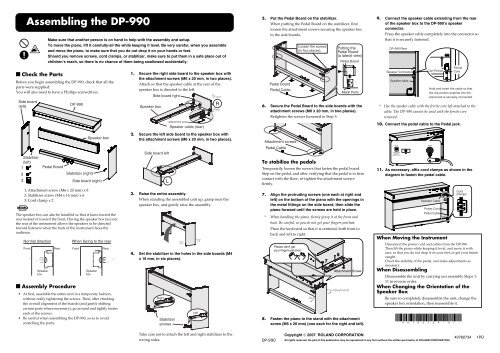
<strong>Assembling</strong> <strong>the</strong> <strong>DP</strong>-<strong>990</strong><br />
Make sure that ano<strong>the</strong>r person is on hand to help with <strong>the</strong> assembly and setup.<br />
To move <strong>the</strong> piano, lift it carefully-all <strong>the</strong> while keeping it level. Be very careful, when you assemble<br />
and move <strong>the</strong> piano, to make sure that you do not drop it on your hands or feet.<br />
Should you remove screws, cord clamps, or stabilizer, make sure to put <strong>the</strong>m in a safe place out of<br />
children’s reach, so <strong>the</strong>re is no chance of <strong>the</strong>m being swallowed accidentally.<br />
5. Put <strong>the</strong> Pedal Board on <strong>the</strong> stabilizer.<br />
When putting <strong>the</strong> Pedal Board on <strong>the</strong> stabilizer, first<br />
loosen <strong>the</strong> attachment screws securing <strong>the</strong> speaker box<br />
to <strong>the</strong> side boards.<br />
fig.st5.e<br />
Loosen <strong>the</strong> screws<br />
(in four places).<br />
Putting <strong>the</strong><br />
Pedal Board<br />
(a lateral view)<br />
Pedal Board<br />
9. Connect <strong>the</strong> speaker cable extending from <strong>the</strong> rear<br />
of <strong>the</strong> speaker box to <strong>the</strong> <strong>DP</strong>-<strong>990</strong>’s speaker<br />
connector.<br />
Press <strong>the</strong> speaker cable completely into <strong>the</strong> connector so<br />
that it is securely fastened.<br />
fig.st8.e<br />
<strong>DP</strong>-<strong>990</strong> Rear<br />
■ Check <strong>the</strong> Parts<br />
Before you begin assembling <strong>the</strong> <strong>DP</strong>-<strong>990</strong>, check that all <strong>the</strong><br />
parts were supplied.<br />
You will also need to have a Phillips screwdriver.<br />
fig.st900parts.e<br />
Side board<br />
(left)<br />
<strong>DP</strong>-<strong>990</strong><br />
1. Secure <strong>the</strong> right side board to <strong>the</strong> speaker box with<br />
<strong>the</strong> attachment screws (M6 x 20 mm, in two places).<br />
Attach so that <strong>the</strong> speaker cable at <strong>the</strong> rear of <strong>the</strong><br />
speaker box is directed to <strong>the</strong> left.<br />
Speaker box<br />
Side board right<br />
Front<br />
R<br />
Rear<br />
Pedal Board<br />
Pedal Cable<br />
Metal Parts<br />
6. Secure <strong>the</strong> Pedal Board to <strong>the</strong> side boards with <strong>the</strong><br />
attachment screws (M6 x 20 mm, in two places).<br />
Retighten <strong>the</strong> screws loosened in Step 5.<br />
Speaker Connecter<br />
Speaker cable<br />
Clip Portion<br />
Ferrite<br />
Core<br />
Hold and insert <strong>the</strong> cable so that<br />
<strong>the</strong> clip portion extends into <strong>the</strong><br />
stand and is securely connected.<br />
* Use <strong>the</strong> speaker cable with <strong>the</strong> ferrite core left attached to <strong>the</strong><br />
cable. The <strong>DP</strong>-<strong>990</strong> cannot be used with <strong>the</strong> ferrite core<br />
removed.<br />
Attachment screw<br />
Speaker cable (rear)<br />
fig.st6.e<br />
10. Connect <strong>the</strong> pedal cable to <strong>the</strong> Pedal jack.<br />
Speaker box<br />
2. Secure <strong>the</strong> left side board to <strong>the</strong> speaker box with<br />
<strong>the</strong> attachment screws (M6 x 20 mm, in two places).<br />
fig.st1.e<br />
Attachment screws<br />
Pedal Cable<br />
Stabilizer<br />
(left)<br />
1<br />
2<br />
3<br />
Pedal Board<br />
Stabilizer (right)<br />
Side board (right)<br />
Side board left<br />
L<br />
To stabilize <strong>the</strong> pedals<br />
Temporarily loosen <strong>the</strong> screws that fasten <strong>the</strong> pedal board.<br />
Step on <strong>the</strong> pedal, and after verifying that <strong>the</strong> pedal is in firm<br />
contact with <strong>the</strong> floor, re-tighten <strong>the</strong> attachment screws<br />
firmly.<br />
11. As necessary, affix cord clamps as shown in <strong>the</strong><br />
diagram to fasten <strong>the</strong> pedal cable.<br />
fig.st9.e<br />
1: Attachment screw (M6 x 20 mm) x 8<br />
2: Stabilizer screw (M4 x 16 mm) x 6<br />
3: Cord clamp x 2<br />
The speaker box can also be installed so that it faces toward <strong>the</strong><br />
rear instead of toward <strong>the</strong> front. Having <strong>the</strong> speaker box face out<br />
<strong>the</strong> rear of <strong>the</strong> instrument allows <strong>the</strong> speakers to be directed<br />
toward listeners when <strong>the</strong> back of <strong>the</strong> instrument faces <strong>the</strong><br />
audience.<br />
fig.stsp.e<br />
Normal direction<br />
Front<br />
Speaker<br />
box<br />
Rear<br />
■ Assembly Procedure<br />
When facing to <strong>the</strong> rear<br />
Front<br />
Speaker<br />
box<br />
Rear<br />
• At first, assemble <strong>the</strong> entire unit in a temporary fashion,<br />
without really tightening <strong>the</strong> screws. Then, after checking<br />
<strong>the</strong> overall alignment of <strong>the</strong> boards (and gently shifting<br />
certain parts where necessary), go around and tightly fasten<br />
each of <strong>the</strong> screws.<br />
• Be careful when assembling <strong>the</strong> <strong>DP</strong>-<strong>990</strong>, so as to avoid<br />
scratching <strong>the</strong> parts.<br />
3. Raise <strong>the</strong> entire assembly.<br />
When standing <strong>the</strong> assembled unit up, grasp near <strong>the</strong><br />
speaker box, and gently raise <strong>the</strong> assembly.<br />
fig.st4<br />
4. Set <strong>the</strong> stabilizer in <strong>the</strong> holes in <strong>the</strong> side boards (M4<br />
x 16 mm, in six places).<br />
fig.st3.e<br />
Right<br />
Stabilizer<br />
screws<br />
Rear<br />
Left<br />
Front<br />
7. Align <strong>the</strong> protruding screws (one each at right and<br />
left) on <strong>the</strong> bottom of <strong>the</strong> piano with <strong>the</strong> openings in<br />
<strong>the</strong> metal fittings on <strong>the</strong> side board, <strong>the</strong>n slide <strong>the</strong><br />
piano forward until <strong>the</strong> screws are held in place.<br />
* When handling <strong>the</strong> piano, firmly grasp it at <strong>the</strong> front and<br />
back. Be careful, so you do not get your fingers pinched.<br />
Place <strong>the</strong> keyboard so that it is centered, both front to<br />
back and left to right.<br />
Please don’t get<br />
your fingers pinched<br />
Rear<br />
8. Fasten <strong>the</strong> piano to <strong>the</strong> stand with <strong>the</strong> attachment<br />
screw (M6 x 20 mm) (one each for <strong>the</strong> right and left).<br />
7<br />
8<br />
Attachment Screw<br />
Front (Keyboard)<br />
Speaker Cable<br />
Power Cord<br />
Pedal Cable<br />
Cord<br />
Clamps<br />
When Moving <strong>the</strong> Instrument<br />
Disconnect <strong>the</strong> power cord and cables from <strong>the</strong> <strong>DP</strong>-<strong>990</strong>.<br />
Then lift <strong>the</strong> piano while keeping it level, and move it with<br />
care, so that you do not drop it on your feet, or get your hands<br />
caught.<br />
Check <strong>the</strong> stability of <strong>the</strong> pedal, and make adjustments as<br />
necessary.<br />
When Disassembling<br />
Disassemble <strong>the</strong> unit by carrying out assembly Steps 1-<br />
11 in reverse order.<br />
When Changing <strong>the</strong> Orientation of <strong>the</strong><br />
Speaker Box<br />
Be sure to completely disassemble <strong>the</strong> unit, change <strong>the</strong><br />
speaker box orientation, <strong>the</strong>n reassemble it.<br />
* 4 0 7 8 2 7 3 4 - 0 1 *<br />
fig.st7.e<br />
Take care not to attach <strong>the</strong> left and right stabilizer to <strong>the</strong><br />
wrong sides.<br />
<strong>DP</strong>-<strong>990</strong><br />
Copyright © 2007 ROLAND CORPORATION<br />
All rights reserved. No part of this publication may be reproduced in any form without <strong>the</strong> written permission of ROLAND CORPORATION.<br />
40782734 1PD
■ <br />
<br />
<br />
<br />
<br />
<br />
<br />
<br />
<br />
<br />
<br />
<br />
<br />
<br />
1<br />
<br />
2<br />
<br />
3<br />
<br />
<br />
<br />
<br />
<br />
<br />
<br />
<br />
<br />
■ <br />
<br />
<br />
<br />
<br />
<br />
<br />
<br />
<br />
<br />
• <br />
<br />
• <br />
<br />
<br />
• <br />
<br />
1. <br />
<br />
<br />
<br />
<br />
2. <br />
<br />
<br />
3. <br />
<br />
<br />
<br />
<br />
<br />
4. <br />
<br />
<br />
<br />
R<br />
<br />
<br />
<br />
<br />
<br />
<br />
L <br />
<br />
<br />
<br />
<br />
5. <br />
<br />
<br />
<br />
<br />
<br />
<br />
6. <br />
<br />
<br />
<br />
<br />
<br />
<br />
<br />
<br />
<br />
<br />
<br />
<br />
7. <br />
<br />
<br />
<br />
<br />
<br />
<br />
<br />
<br />
<br />
<br />
<br />
8. <br />
<br />
<br />
<br />
7<br />
<br />
<br />
<br />
<br />
8<br />
<br />
<br />
<br />
9. <br />
<br />
<br />
<br />
<br />
<br />
<br />
<br />
10. <br />
11.<br />
<br />
<br />
<br />
<br />
<br />
<br />
<br />
<br />
<br />
<br />
<br />
<br />
<br />
<br />
<br />
<br />
<br />
<br />
<br />
<br />
<br />
<br />
<br />
<br />
<br />
<br />
<br />
<br />
<br />
<strong>DP</strong>-<strong>990</strong> ©