Nice OXI Plug-In 4-Channel Receiver - Rolling Center
Nice OXI Plug-In 4-Channel Receiver - Rolling Center
Nice OXI Plug-In 4-Channel Receiver - Rolling Center

Create successful ePaper yourself
Turn your PDF publications into a flip-book with our unique Google optimized e-Paper software.
<strong>In</strong>stallation and use instructions<br />
and warnings<br />
Istruzioni ed avvertenze per<br />
l’installazione e l’uso<br />
<strong>In</strong>structions et avertissements pour<br />
l’installation et l’utilisation<br />
Anweisungen und Hinweise für die<br />
<strong>In</strong>stallation und die Bedienung<br />
<strong>In</strong>strucciones y advertencias para<br />
la instalación y el uso<br />
<strong>In</strong>strukcje i ostrzeżenia związane z<br />
instalowaniem i użytkowaniem<br />
Aanwijzingen en aanbevelingen<br />
voor installering en gebruik<br />
<strong>Nice</strong>One<br />
<strong>Receiver</strong><br />
<strong>OXI</strong> family<br />
OX2 family<br />
Europe: 0682
EN<br />
EN – Models with “SM” type connection<br />
IT – Modelli con connessione a innesto “SM”<br />
FR – Modèles avec connecteur embrochable «SM»<br />
ES – Modelos con conexión con conector “SM”<br />
DE – Modelle mit Steckverbindung “SM”<br />
PL – Modele z połączeniem za pomocą złącza<br />
typu “SM”<br />
NL – Modellen met steekconnector “SM”<br />
EN – Models with universal type connection<br />
IT – Modelli con connessione universale<br />
FR – Modèles avec connecteur universel<br />
ES – Modelos con conexión universal<br />
DE – Modelle mit Universalverbindung<br />
PL – Modele z połączeniem uniwersalnym<br />
NL – Modellen met universele aansluiting<br />
2
ENGLISH<br />
1 – PRODUCT DESCRIPTION AND<br />
INTENDED USE<br />
This receiver is part of the series “<strong>Nice</strong>One” produced by <strong>Nice</strong><br />
spa. The receivers in this series are destined for use on the<br />
control units fitted on systems for the automation of gates,<br />
garage doors and road barriers. Any use other than as<br />
specified herein is to be considered improper and is<br />
strictly prohibited! The manufacturer denies all liability for<br />
damage deriving from improper use of the product and<br />
use other than as specified in this manual.<br />
Various models are available, with the specifications as stated<br />
in the table below.<br />
1.1 – The “<strong>Nice</strong>Opera” system<br />
The receivers in the series <strong>Nice</strong>One are part of the “<strong>Nice</strong>-<br />
Opera” system. This system has been designed to simplify<br />
the programming phases, use and maintenance of the de -<br />
vices normally used in automation systems. The system comprises<br />
various software and hardware devices capable of<br />
intercommunicating via radio, by means of the “O-Code”<br />
encoding system or a “physical” connection via cable.<br />
The main devices that make up the <strong>Nice</strong>Opera system are:<br />
– <strong>Nice</strong>One transmitters;<br />
– <strong>Nice</strong>One receivers;<br />
– O-box programming unit;<br />
– Control units and gearmotors with “T4 Bus”;<br />
– O-View programmer for devices with “T4 Bus”.<br />
IMPORTANT – For further details on all functions of the<br />
<strong>Nice</strong>Opera system and interdependency of the various<br />
devices in the system, refer to the general manual “<strong>Nice</strong>-<br />
Opera System Book”, also available on the <strong>In</strong>ternet site<br />
www.niceforyou.com.<br />
EN<br />
Mod. Frequency Function Connection<br />
<strong>OXI</strong> 433.92 MHz <strong>Receiver</strong> Connector type<br />
<strong>OXI</strong>FM 868.46 MHz <strong>Receiver</strong> Connector type<br />
<strong>OXI</strong>T 433.92 MHz <strong>Receiver</strong>-transmitter Connector type<br />
<strong>OXI</strong>TFM 868.46 MHz <strong>Receiver</strong>-transmitter Connector type<br />
OX2 433.92 MHz <strong>Receiver</strong> with 6-core cable<br />
OX2FM 868.46 MHz <strong>Receiver</strong> with 6-core cable<br />
OX2T 433.92 MHz <strong>Receiver</strong>-transmitter with 6-core cable<br />
OX2TFM 868.46 MHz <strong>Receiver</strong>-transmitter with 6-core cable<br />
Notes to table:<br />
– The frequencies 433.92<br />
MHz and 868.46 MHz are<br />
not compatible.<br />
– The letter “T” in the model<br />
name indicates a receiver with<br />
built-in transmitter.<br />
3
EN<br />
2 – FUNCTIONAL PRODUCT<br />
SPECIFICATIONS<br />
• For all models<br />
– The receiver manages “O-Code” radio encoding with variable<br />
code (rolling-code), which enables use of all the new<br />
functions in the <strong>Nice</strong>Opera system.<br />
The receiver is compatible also with “FloR”, “TTS”, “Smilo”<br />
and “Flo” encoding systems. However, in this case some of<br />
the exclusive <strong>Nice</strong>Opera system functions described in<br />
this manual cannot be used.<br />
– The receiver has a capacity of 1024 spaces in which to<br />
memorise transmitters. If the transmitter is memorised in<br />
“Mode I”, all the relative keys will occupy 1 memory allocation;<br />
otherwise if memorised in “Mode II”, each memorised<br />
key will occupy 1 memory allocation (for memorisation procedures,<br />
see below in this manual).<br />
– Each receiver has its own identification number called a<br />
“Certificate”.<br />
This number enables access to a series of operations, such<br />
as: Memorisation of new transmitters without the need for<br />
direct intervention on the receiver and use of the O-View<br />
unit, by means of the “T4 Bus” connection.<br />
The sealed coupon in the product pack contains the sheet<br />
with the certificate number of this receiver. Caution! – this<br />
coupon must be kept in a safe place as it enables access to<br />
data stored in the receiver, unless further protection measures<br />
are adopted, such as the use of a security password.<br />
• For models with “SM” type connection<br />
– These models can be used exclusively with the control units<br />
fitted with an “SM” type connection (fig. 1). Note – to identify<br />
compatible control units, refer to the <strong>Nice</strong> product catalogue.<br />
– These models automatically recognise the characteristics of<br />
the control unit to which they are connected and the receiver<br />
self-installs as follows.<br />
• If the control unit manages the “T4 Bus”, the receiver<br />
provides up to 15 different commands.<br />
• If the control unit does not manage the “T4 Bus”, the<br />
receiver provides up to 4 different command channels.<br />
Caution! – <strong>In</strong> both cases the number and variety of the<br />
commands available depend on the type and model of control<br />
unit used. The “Table of commands” of each control unit<br />
is provided in the instruction manual of the relative control<br />
unit.<br />
• For models with universal type connection<br />
– These models operate with 2 voltage-free contact relays<br />
and therefore can be used with any type of control unit.<br />
• For models with “T” in the model name<br />
– These models are equipped with a “Repeater” function (see<br />
below in this manual) which enables an increase in the transmission<br />
range of the transmitters. They also enable “wireless”<br />
communication with the O-Box programming unit.<br />
4
3 – PRODUCT INSTALLATION<br />
• For models with “SM” type connection<br />
These models are connected to the control unit by inserting<br />
the connector in the relative control unit connector (fig. 1).<br />
Caution! – Before connecting or removing the receiver,<br />
disconnect the control unit from the power supply.<br />
The aerial supplied must also be installed, connecting it to the<br />
specific terminals on the control unit.<br />
• For models with universal type connection<br />
––– Power supply selection –––<br />
These models are connected to the control unit by means of a<br />
6-core cable. Before connecting the cable, select the type of<br />
power supply required, leaving or removing the electric jumper<br />
as necessary (fig. 2-a) as follows:<br />
– Jumper NOT inserted = 24 V ac/dc<br />
(voltage limits: 18 ÷ 28 V)<br />
– Jumper INSERTED = 12 V ac/dc<br />
(voltage limits: 10 ÷ 18 V)<br />
2<br />
a<br />
EN<br />
IT<br />
1<br />
5
EN<br />
3<br />
Red<br />
Black<br />
White<br />
White<br />
Purple<br />
Purple<br />
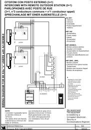
––– Electrical connections –––<br />
Connect the 6 wires of the receiver cable to the relative terminals<br />
of the control unit as follows (fig. 3):<br />
•Redand Black = POWER SUPPLY<br />
(red = Positive, black = Negative. <strong>In</strong> AC this is not important).<br />
• White and White = RELAY 1 OUTPUT<br />
(voltage-free contact of a normally open relay).<br />
• Purple and Purple = RELAY 2 OUTPUT<br />
(voltage-free contact of a normally open relay).<br />
–– How to obtain “NC” type contacts ––<br />
The outputs are controlled by 2 relays with NO (normally open)<br />
type contact. To change to NC (normally closed) type contact,<br />
proceed as follows:<br />
01. Disconnect the receiver from the power supply.<br />
02. Open the box of the receiver by first raising the smaller<br />
section of the cover (fig. 4-a) and then the larger section<br />
with the key (fig. 4-b).<br />
03. Carefully remove the board and turn it over: the side with<br />
the soldered elements must be facing the user.<br />
04. On the side with the soldered elements, proceed as follows<br />
(fig. 5):<br />
– Cut the traced section at point “X”<br />
– Join the contacts with a drop of tin at points “Y”.<br />
Note – these modifications may be applied to one or<br />
both relays as required.<br />
a<br />
6
4<br />
5<br />
EN<br />
a<br />
b<br />
7
EN<br />
• For all models:<br />
<strong>In</strong>stallation of an external aerial<br />
If the aerial supplied is in an unfavourable position and the<br />
radio signal is weak, an external aerial may be installed to<br />
improve reception (mod. ABF or ABFKIT). The new aerial must<br />
be positioned as high as possible and above any metal or<br />
reinforced concrete structures present in the area.<br />
– Connection to the Control Unit: Use a coaxial cable with<br />
an impedance of 50 ohm (for example, a RG58 cable with<br />
low loss). Caution! – To reduce signal dispersion use a<br />
cable that is as short as possible (not exceeding 10 m).<br />
– Connection to the receiver (only for models with universal<br />
type connection): Open the receiver by first raising the<br />
smaller section of the cover (fig. 4-a) and disconnect the<br />
aerial supplied; then connect the cable of the new aerial to<br />
terminal 1 and 2 as follows (fig. 3-a): Terminal 1 = sheath;<br />
Terminal 2 = core.<br />
PROGRAMMING THE<br />
MAIN FUNCTIONS<br />
Programming warnings<br />
The settings described in this chapter (except for procedure<br />
6) require use of the key and led on the receiver (fig.<br />
6). To indicate the state of activity in progress, the led<br />
emits a set number of flashes with a specific duration and<br />
colour (green, red or orange). For the meaning of these<br />
signals, refer to Table A at the end of the manual.<br />
6<br />
Led<br />
Key<br />
Led<br />
Key<br />
8
4 – CAUTION! – READ THIS SECTION<br />
BEFORE MEMORISING THE<br />
TRANSMITTER<br />
The receiver can only memorise transmitters belonging to one<br />
of the following 3 encoding families:<br />
– family with “O-Code”, “FloR” and “TTS” encoding;<br />
– family with “Flo” encoding;<br />
– family with “Smilo” encoding.<br />
Note – Each code enables use exclusively of the standard<br />
associated functions on the receiver.<br />
Caution! – The encoding family of the first transmitter<br />
memorised on the receiver also defines the relative<br />
encoding family for the subsequent transmitters to be<br />
memorised.<br />
To change the encoding family set on the receiver, perform<br />
procedure 10 – Total receiver memory deletion.<br />
To check on the receiver whether transmitters and the associated<br />
encoding family are already memorised, proceed as follows:<br />
01. Disconnect the receiver from the power supply.<br />
02. Re-connect the power to the receiver and count the<br />
number of green flashes emitted by the receiver led.<br />
03. Check the number of flashes emitted with the data in the<br />
table below:<br />
– 1 flash = Flo encoding<br />
– 2 flashes = O-Code / FloR / TTS encoding<br />
– 3 flashes = Smilo encoding<br />
– 5 flashes = no transmitter entered<br />
Caution! – Before memorising a transmitter, carefully<br />
read all memorisation procedures described below to<br />
select the one most suited to your specific application.<br />
5 – TRANSMITTER MEMORISATION<br />
PROCEDURE: “Mode I” AND “Mode II”<br />
Each control unit has a set number of commands that can be<br />
activated according to the type of receiver: The models with<br />
“SM” connector provide 4 or 15 commands while models<br />
with the universal connection provide 2 outputs.<br />
<strong>In</strong> general the commands can be associated with the transmitter<br />
keys in two ways:<br />
• “Mode I”. This mode enables memorisation on the receiver<br />
of all transmitter keys or a group of the latter at once (on transmitters<br />
with more than one identity code such as model ON9).<br />
The keys are automatically associated with the pre-set commands<br />
of the control unit or the receiver outputs, on models<br />
with universal connectotion.<br />
• “Mode II”. This mode enables memorisation on the receiver<br />
of a single transmitter key. The user has a free choice of<br />
which command, among those available on the control unit<br />
(maximum 4) or which output of the receiver to be associated<br />
with the selected key.<br />
– “Extended Mode II” (only for models with “SM” connector).<br />
This mode can only be used with control units using the connection<br />
system “T4 Bus”. The “Extended Mode II” is the same<br />
as “Mode II” with the additional option to choose the required<br />
command from those available in the “Table of commands”<br />
(maximum 15), as provided in the manual of the control unit<br />
connected to the receiver.<br />
EN<br />
9
EN<br />
10<br />
5.1 – Memorisation in “MODE I”<br />
Warning – This procedure simultaneously memorises all<br />
keys of the transmitter or a group of the latter (on transmitters<br />
with more than one identity code).<br />
01. Press and hold the key on the receiver until the green led<br />
on the receiver illuminates. Then release the key.<br />
02. (within 10 seconds) On the transmitter to be memorised,<br />
press and hold any key until the led on the receiver emits<br />
the first of 3 green flashes to confirm memorisation.<br />
Note – After the three flashes, a 10-second interval is available<br />
to memorise another transmitter as required.<br />
5.2 – Memorisation in “MODE II”<br />
(valid also for “Extended Mode II”)<br />
WARNINGS:<br />
– The “Extended Mode II” procedure can only be used<br />
with receivers with “SM” type connectors.<br />
– This procedure enables memorisation of a single transmitter<br />
key.<br />
01. <strong>In</strong> the control unit manual, look up the “Table of commands”,<br />
select the command to assign to the transmitter<br />
key and note the number corresponding to the command.<br />
02. (on the receiver) Press the key the same number of times<br />
as the previously noted number – the Led on the receiver<br />
emits the same number of flashes repeated at regular<br />
intervals.<br />
03. (on the transmitter within 10 seconds) Press and hold the<br />
selected key for memorisation until the led on the receiver<br />
emits the first of 3 flashes (= memorisation confirmed).<br />
Note – After the three flashes, a 10-second interval is available<br />
to memorise the same command on other keys on the<br />
same transmitter or a new transmitter as required.<br />
6 – MEMORISING A TRANSMITTER USING<br />
THE “ENABLE CODE” OF ANOTHER<br />
TRANSMITTER [already memorised]<br />
This procedure can only be used if two transmitters with<br />
“O-Code” encoding are used.<br />
The <strong>Nice</strong>One transmitters have a secret code stored in the<br />
memory, known as the “ENABLE CODE”. Thanks to this<br />
code, operation of NEW transmitter can be enabled by simply<br />
transferring the “enable code” of an OLD transmitter (previously<br />
memorised on the receiver) onto its memory (fig. 8).<br />
Note – For this procedure, refer to the transmitter manual.<br />
Subsequently, when the NEW transmitter is used, it will transmit<br />
its own identity code to the receiver as well as the relative<br />
“enable code” (the first twenty times only). The receiver, after<br />
recognising the “enable code” of an OLD transmitter (previously<br />
memorised on the receiver) automatically memorises the<br />
identity code of the NEW transmitter sent to it.<br />
8
• Preventing accidental use of this memorisation procedure<br />
To prevent memorisation on the receiver of other transmitters<br />
not compatible with the system but with the “enable code” of<br />
a transmitter already memorised on the receiver, this procedure<br />
can be “locked” (or unlocked) by programming the function<br />
in paragraph 10.<br />
As an alternative to locking memorisation of the entire receiver,<br />
transfer of the “enable code” can be disabled exclusively for<br />
some or all OLD transmitters already memorised. This operation<br />
can be performed using the O-Box programming unit.<br />
7 – MEMORISATION OF A TRANSMITTER<br />
USING THE PROCEDURE IN THE<br />
VICINITY OF THE RECEIVER<br />
[with a transmitter already memorised]<br />
A NEW transmitter can be memorised in the receiver memory<br />
without acting directly on the key of the receiver, but by simply<br />
working within its reception range. To use this procedure, an<br />
OLD transmitter, previously memorised (in “Mode I” or in<br />
“Mode II”) and operative, is required. The procedure enables<br />
the NEW transmitter to receive the settings of the OLD version.<br />
WARNINGS:<br />
• Use only one of the two procedures described below,<br />
according to requirements.<br />
• The procedure must be performed within the reception<br />
range of the receiver (maximum 10-20 m from receiver).<br />
• Repeat the same procedure for each transmitter to be<br />
memorised.<br />
Standard Procedure (valid for all <strong>Nice</strong> receivers)<br />
01. On the NEW transmitter, press and hold the key…. for at<br />
least 5 seconds (see note 1) and then release.<br />
02. On the OLD transmitter, press key…. three times (see<br />
note 1) and then release.<br />
03. On the NEW transmitter, press the same key pressed in<br />
point 01 once and then release.<br />
Alternative Procedure (valid for this receiver only)<br />
01. On the NEW transmitter, press and hold the key…. for at<br />
least 3 seconds (see note 1) and then release.<br />
02. On the OLD transmitter, press and hold the key…. for at<br />
least 3 seconds see note 1) and then release.<br />
EN<br />
11
EN<br />
12<br />
03. On the NEW transmitter, press the same key pressed in<br />
point 01 for at least 3 seconds and then release.<br />
04. On the OLD transmitter, press the same key pressed in<br />
point 02 for at least 3 seconds and then release.<br />
Note 1:<br />
If the OLD transmitter is memorised in “Mode I” the NEW<br />
transmitter will also be memorised in “Mode I”. <strong>In</strong> this case,<br />
during the procedure press any key on either the OLD or NEW<br />
transmitter.<br />
If the OLD transmitter is memorised in “Mode II” the NEW<br />
transmitter will also be memorised in “Mode II”. <strong>In</strong> this case,<br />
during the procedure press the required command key on the<br />
OLD transmitter and the associated key to be memorised for<br />
this command on the NEW transmitter. This procedure must<br />
also be repeated for each key of the NEW transmitter to be<br />
memorised.<br />
• Preventing accidental use of this memorisation procedure<br />
To prevent the continuous reception of a signal transmitted at<br />
random by a transmitter not part of the system from accidentally<br />
activating the memorisation procedure, this procedure<br />
can be “locked” (or unlocked) by programming the function in<br />
paragraph 10.<br />
8 – TOTAL RECEIVER MEMORY DELETION<br />
All transmitters memorised can be deleted from the receiver<br />
memory, or all data present in the latter can be deleted as<br />
follows:<br />
01. Press and hold the receiver key and check the following<br />
changes in Led status:<br />
– (after approx. 4 seconds) the green led illuminates;<br />
– (after approx. 4 seconds) the green led turns off;<br />
– (after approx. 4 seconds) the green led starts flashing.<br />
02. At this point release the key exactly......<br />
• on the 3rd flash, to delete all transmitters, or,<br />
• on the 5th flash, to delete the entire memory of the<br />
receiver, including configurations and encoding families of<br />
the transmitters.<br />
Alternatively this function can be performed using the O-Box<br />
or O-View programming unit.<br />
9 – DELETING A SINGLE TRANSMITTER<br />
FROM THE RECEIVER MEMORY<br />
A single transmitter (in your possession) memorised can be<br />
deleted from the receiver memory as follows:<br />
01. Press and hold the receiver key.<br />
02. After approx. 4 seconds the green led illuminates (keep<br />
the key pressed).<br />
03. On the transmitter to be deleted from the memory, press<br />
and hold any key (see note 1) until the led on the receiver<br />
emits 5 green flashes (= deletion confirmed).
Note 1:<br />
If the transmitter is memorised in “Mode I” any key can be<br />
pressed.<br />
If the transmitter is memorised in “Mode II” the entire procedure<br />
must be repeated for each memorised key to be deleted.<br />
Alternatively this function can be performed using the O-Box<br />
or O-View programming unit.<br />
• Led ORANGE = Both memorisation modes locked (“in<br />
the vicinity” and with “enable code”).<br />
04. (within 5 seconds) Press any key of a transmitter already<br />
memorised on the receiver to save the selected function.<br />
Alternatively the lock (or unlock) function can be applied using<br />
the O-Box or O-View programming unit.<br />
EN<br />
10 – ENABLING (or disabling)<br />
THE RECEIVER FOR TRANSMITTER<br />
MEMORISATION<br />
This function enables the user to prevent memorisation of new<br />
transmitters when the procedures “in the vicinity” (factory<br />
setting is ON) or with “enable code” (factory setting is ON)<br />
are used as described in this manual. To enable or disable this<br />
function, proceed as follows:<br />
01. Disconnect the receiver from the power supply and wait 5<br />
seconds.<br />
02. Reconnect the power and switch on by pressing the<br />
receiver key until the relative led has completed the signals<br />
indicating the type of code stored in the memory<br />
(see paragraph 5) and the procedure is activated, indicated<br />
by 2 short orange flashes. Then release the key.<br />
03. (within 5 seconds) Press the receiver key repeatedly to<br />
select one of the following functions (Warning! – on each<br />
press of the key the Led changes colour to indicate the<br />
currently selected function):<br />
• Led OFF = No lock enabled<br />
• Led RED = Memorisation “in the vicinity” locked<br />
• Led GREEN = Memorisation with “enable code” locked<br />
13
EN<br />
OTHER FUNCTIONS<br />
WARNING – The settings described in this chapter<br />
require use of the O-Box or O-View programming unit.<br />
For operation of these devices, refer to the relative<br />
instruction manuals, also available on the internet site:<br />
www.niceforyou.com.<br />
• The models with “SM” connector are connected to the<br />
O-Box unit by inserting the receiver in the relative connector.<br />
• The models with universal connector are connected to<br />
the O-Box unit by means of a special cable (fig. 7-a)<br />
which must be connected to the connector on the receiver<br />
(see fig. 7-b).<br />
7<br />
11 – MEMORISATION OF A TRANSMITTER<br />
USING THE RECEIVER<br />
“CERTIFICATE NUMBER”<br />
[with O-Box] – This procedure can only be used if a transmitter<br />
is used with “O-Code” encoding and when in possession<br />
of the receiver “Certificate Number”.<br />
The “CERTIFICATE” is a personal number (factory set) identifying<br />
the single receiver to distinguish it from all others.<br />
Use of this “certificate” simplifies the procedure required to<br />
memorise the transmitter in the receiver, as it no longer obliges<br />
the installer to work within the receiver operating range. <strong>In</strong><br />
fact the new procedure enables transmitter memorisation<br />
from any distance, even far from the installation site (for example<br />
from the installer’s office – fig. 9).<br />
9<br />
14
<strong>In</strong>itially, the procedure consists in the installer entering, with<br />
the aid of the programming unit “O-Box”, the required functions<br />
and the relative receiver “certificate” in the memory of<br />
the transmitter. The transmitter, ready to use, is then sent to<br />
the client.<br />
Subsequently, when the transmitter is used, it will transmit the<br />
command along with the “certificate” to the receiver (the first<br />
twenty times only). The receiver, after recognising the “certificate”<br />
as its own, automatically memorises the identity code of<br />
the transmitter that sent the certificate.<br />
12 – REMOTE REPLACEMENT OF A<br />
TRANSMITTER USING “PRIORITY”<br />
MODE<br />
[with O-Box] – The identity code of a transmitter in the<br />
<strong>Nice</strong>One series is accompanied by a number (from 0 to 3),<br />
which enables the user to specify the transmitter’s priority<br />
level on a receiver with respect to any other transmitters with<br />
the same code.<br />
This “priority” serves to replace, and thus disable, use of a<br />
transmitter that has been lost or stolen, without the need to<br />
return to the client’s system.<br />
Use of priority mode requires knowledge of the code of the<br />
lost transmitter and enables maintenance of the same code<br />
and functions of the previous transmitter.<br />
Therefore the lost transmitter can be disabled by simply<br />
updating the priority level of the new transmitter with the<br />
next highest value.<br />
On first use of the transmitter, the receiver memorises the new<br />
priority level received and ignores any command sent by the<br />
lost or stolen transmitter if subsequently used.<br />
This function can be enabled (or disabled) on the receiver (factory<br />
setting ON) and, when active, the receiver does not<br />
update the priority level sent by the transmitter.<br />
13 – ENABLING (or disabling)<br />
RECEPTION OF NON-ORIGINAL<br />
“IDENTITY CODES”<br />
[with O-Box / O-View] – The identity codes of transmitters<br />
with “FloR” and “O-Code” encoding can be modified as<br />
required, using the “O-Box” or “O-View” programming unit.<br />
The receiver can normally recognise whether a code is original<br />
(factory set) or modified.<br />
When this function is enabled or disabled (factory setting ON)<br />
the receiver has the option to accept (or not) the command of<br />
a transmitter with a modified identity code.<br />
14 – LOCKING (or unlocking)<br />
THE MOBILE SECTION (<strong>Rolling</strong> code)<br />
OF THE IDENTITY CODE<br />
[with O-Box / O-View] – This function enables the user to<br />
lock (or unlock) management on the receiver of the variable<br />
section (rolling code) of an identity code sent by a transmitter.<br />
When the lock function is active (factory setting OFF), the<br />
receiver treats a “rolling code” as if it were a “fixed” code,<br />
ignoring the variable section.<br />
EN<br />
15
EN<br />
15 – ENABLING (or disabling)<br />
THE “REPEATER” FUNCTION<br />
(Function available only on models <strong>OXI</strong>T, <strong>OXI</strong>TFM, OX2T,<br />
OX2TFM, in combination with transmitters using O-Code<br />
encoding).<br />
[with O-Box] – If an automation is to be controlled at a distance<br />
greater than that normally covered by the transmitter<br />
and receiver, a second receiver may be used (up to a maximum<br />
of five) serving to re-transmit, via radio, the command to<br />
the final receiver (in which the sending transmitter identity<br />
code is memorised), so that this can execute the command.<br />
To enable or disable this function (factory setting OFF) programming<br />
must be performed both on the additional receivers<br />
and transmitters.<br />
16 – MANAGING RELEASE OF THE<br />
TRANSMITTER KEYS<br />
(Function available only on transmitters using O-Code<br />
encoding)<br />
[with O-Box / O-View] – Normally, after sending a command,<br />
on release of the key the manoeuvre is not stopped<br />
immediately but proceeds for a very short pre-set interval.<br />
If necessary, the manoeuvre can be interrupted at the exact<br />
time of key release (required for example during minimal<br />
adjustments) by enabling this function (factory setting OFF).<br />
17 – ENABLING (or disabling)<br />
COMMAND DELIVERY ON THE<br />
“T4 BUS” NETWORK<br />
[with O- View] – On systems in which connection is via the<br />
“T4 Bus”, if more than one receiver is installed, and there is the<br />
need for control at a distance greater than that normally covered<br />
by the transmitter and receiver, this function can be<br />
enabled (on at least 2 receivers) to increase the receiver<br />
reception range.<br />
This enables the receiver that receives a command “via radio”<br />
to re-transmit the command via the Bus cable to the final<br />
receiver (in which the sending transmitter identity code is<br />
memorised), so that this can execute the command.<br />
To enable or disable the option to receiver and/or send radio<br />
codes on the “T4 Bus” in a receiver (factory setting OFF), the<br />
receivers concerned must be duly programmed, using the O-<br />
View programming unit.<br />
18 – CREATING THE “FAMILY GROUPS”<br />
OF TRANSMITTERS<br />
[with O-Box] – Each code memorised on the receiver can<br />
be associated with one or more “family groups”, from the 4<br />
available.<br />
The formation of groups and their activation or deactivation (factory<br />
setting OFF) is managed by means of the O-Box programming<br />
unit while use of the groups, for example in a set timeband,<br />
is managed by means of the O-View programming unit.<br />
16
19 – PROTECTION OF PROGRAMMED<br />
FUNCTION SETTINGS<br />
[with O-Box / O-View] – This function enables the user to<br />
protect all programmed functions on the receiver, also disabling<br />
functionality of the key and relative led. The function is<br />
enabled by entering a password on the receiver, i.e. a maximum<br />
of 10 digits, as set by the installer.<br />
When the function is enabled, before programming and maintenance<br />
of the receiver, the special password must be entered<br />
on the programming unit to unlock the receiver.<br />
DISPOSAL OF THE PRODUCT<br />
This product constitutes an integral part of the automation<br />
system, therefore it must be disposed of along with it.<br />
As in installation, also at the end of product lifetime, the disassembly<br />
and scrapping operations must be performed by qualified<br />
personnel.<br />
This product is made up of different types of material, some of<br />
which can be recycled while others must be disposed of. Seek<br />
information on the recycling and disposal systems envisaged<br />
by the local regulations in your area for this product category.<br />
Caution! – some parts of the product may contain pollutant or<br />
hazardous substances which, if disposed of into the environment,<br />
may cause serious damage to the environment or physical<br />
health.<br />
As indicated by the symbol on the left,<br />
disposal of this product in domestic<br />
waste is strictly prohibited. Separate the<br />
waste into categories for disposal,<br />
according to the methods envisaged by<br />
current legislation in your area, or return<br />
the product to the retailer when purchasing<br />
a new version.<br />
Caution! – Local legislation may envisage serious fines in the<br />
event of abusive disposal of this product.<br />
EN<br />
17
EN<br />
18<br />
PRODUCT TECHNICAL SPECIFICATIONS<br />
<strong>OXI</strong> <strong>OXI</strong>T <strong>OXI</strong>FM <strong>OXI</strong>TFM<br />
• Decoding<br />
“O-Code” / “FloR” / “TTS”; or “Flo”; or “Smilo”<br />
• Maximum absorption<br />
30 mA<br />
• Reception frequency 433.92 MHz 868.46 MHz<br />
• Transmission frequency ––– 433.92 MHz ––– 868.46 MHz<br />
• Sensitivity Above 0.5 µV Above 0.8 µV<br />
• Operating temperature<br />
–20° C ÷ +55° C<br />
• Outputs<br />
4 (on “SM” connector)<br />
• Dimensions and weight L. 50; H. 45; P. 19 mm; weight 20<br />
• Radiated power ––– approx. 1 mW E.R.P. ––– approx. 1 mW E.R.P.<br />
• <strong>In</strong>put impedance<br />
52 ohm<br />
OX2 OX2T OX2FM OX2TFM<br />
• Decoding<br />
“O-Code” / “FloR” / “TTS”; or “Flo”; or “Smilo”<br />
• Power supply<br />
Without electric jumper = 24 V standard. Limits from 18 to 28 V direct or alternating<br />
With electric jumper = 12 V standard. Limits from 10 to 18 V direct or alternating<br />
• Absorption on standby<br />
10 mA at 24 Vac<br />
• Absorption with 2 relays activ<br />
80 mA at 24 Vac.<br />
• Reception frequency 433.92 MHz 868.46 MHz<br />
• Transmission frequency ––– 433.92 MHz ––– 868.46 MHz<br />
• Sensitivity Above 0.5 µV Above 0.8 µV<br />
• N° relays 2<br />
• Relay contact<br />
Normally open max 0,5 A and 50 V<br />
• Operating temperature<br />
–20° C ÷ +55° C<br />
• Protection rating IP 30<br />
• Dimensions and weight<br />
58 x 86; H. 22 mm; weight 55 g<br />
• Radiated power ––– approx. 1 mW E.R.P. ––– approx. 1 mW E.R.P.
GENERAL NOTES<br />
EN<br />
As well as the functions and settings described in this<br />
manual, the receiver offers many other features to<br />
enhance performance, safety and ease of use.<br />
All these settings require use of the O-Box (or in some<br />
cases O-View) programming unit.<br />
For further information on the settings available, refer to<br />
the general system manual “<strong>Nice</strong>Opera System Book”, or<br />
the O-Box/ O-View programming unit manual.<br />
• Notes on Product Technical specifications<br />
– The range of the transmitters and reception capacity of the<br />
receivers is strongly influenced by other devices (for example:<br />
alarms, radio headphones etc.) operating in the zone at<br />
the same frequency. <strong>In</strong> these cases, <strong>Nice</strong> cannot guarantee<br />
the effective capacity of its devices.<br />
– All technical specifications stated in this section refer to an<br />
ambient temperature of 20°C (± 5°C).<br />
– <strong>Nice</strong> reserves the right to apply modifications to the product<br />
at any time when deemed necessary, while maintaining the<br />
same functionalities and intended use.<br />
19
EN<br />
20<br />
On start-up:<br />
Table A<br />
SIGNALS EMITTED BY THE<br />
RECEIVER LED<br />
–– Long flashes / GREEN ––<br />
1 ✺ = Code in use: “Flo”<br />
2 ✺ = Code in use: “O-Code”/“FloR”<br />
3 ✺ = Code in use: “Smilo”<br />
5 ✺ = No remote control memorised<br />
During operation:<br />
1 ✺ = <strong>In</strong>dicates that the code received is not stored in the<br />
memory<br />
1 ✺ = During programming, indicates that the code is<br />
already stored in the memory<br />
3 ✺ = Saving code in memory<br />
5 ✺ = Memory deleted<br />
6 ✺ = During programming, indicates that the code is not<br />
authorised for memorisation<br />
8 ✺ = Memory full<br />
––––––––––––––––––––––––––––––––––––––––––––––––––<br />
–– Short flashes / GREEN ––<br />
1 ✺ = “Certificate” not valid for memorisation<br />
2 ✺ = Code cannot be memorised as is transmitting<br />
“certificate”<br />
3 ✺ = During programming, indicates that the code has<br />
been re-synchronised<br />
4 ✺ = Output in “Mode II” not managed on control unit<br />
5 ✺ = During deletion procedure, indicates that the code<br />
has been deleted<br />
5 ✺ = “Certificate” with higher priority that the admissible<br />
value<br />
6 ✺ = Code synchronisation failure<br />
6 ✺ = Code cannot be memorised due to “incorrect key”<br />
––––––––––––––––––––––––––––––––––––––––––––––––––<br />
–– Long flashes / RED ––<br />
1 ✺ = Non-original code block<br />
2 ✺ = Code with lower priority than the authorised value<br />
––––––––––––––––––––––––––––––––––––––––––––––––––<br />
–– Short flashes / RED ––<br />
1 ✺ = “<strong>In</strong> vicinity” programming mode block<br />
1 ✺ = Memorisation by means of “certificate” block<br />
2 ✺ = Memory block (PIN entry)<br />
––––––––––––––––––––––––––––––––––––––––––––––––––<br />
–– Long flashes / ORANGE ––<br />
1 ✺ = <strong>In</strong>dicates that the code is in the memory but<br />
outside the group currently enabled<br />
––––––––––––––––––––––––––––––––––––––––––––––––––<br />
–– Short flashes / ORANGE ––<br />
2 ✺ = <strong>In</strong>dicates activation of block programming<br />
(on start-up)
EC DECLARATION OF CONFORMITY<br />
EN<br />
Note –This Declaration of Conformity contains the individual declarations of conformity for the specified products; it was updated on the issue<br />
date of this manual and the text herein has been drawn up for editorial purposes. A copy of the original declaration for each product can be<br />
requested from <strong>Nice</strong> S.p.a. (TV) I.<br />
The undersigned, Lauro Buoro, in the role of Managing Director, declares under his sole responsibility, that the product:<br />
Manufacturer’s name : <strong>Nice</strong> S.p.a.<br />
Address:<br />
Via Pezza Alta 13, Z.I. Rustignè, 31046 Oderzo (TV) Italy<br />
Type:<br />
<strong>Receiver</strong> and receiver-transmitter for remote control of automations for doors, gates, shutters,<br />
awnings, rolling shutters and similar applications.<br />
Models:<br />
<strong>OXI</strong>, <strong>OXI</strong>T, <strong>OXI</strong>FM, <strong>OXI</strong>TFM<br />
Accessories:<br />
conform with the requirements of the EC directive:<br />
• 1999/5/EC; DIRECTIVE 1999/5/EC OF THE EUROPEAN PARLIAMENT AND COUNCIL of 9 March 1999 regarding<br />
radio equipment and telecommunications terminal equipment and the mutual recognition of their conformity<br />
According to the following harmonised standards<br />
Health protection: EN 50371:2002;<br />
Electrical safety: EN 60950-1:2006;<br />
Electromagnetic compatibility : EN 301 489-1V1.6.1:2006; EN 301 489-3V1.4.1:2002<br />
Radio range: EN 300220-2V2.1.2:2007<br />
Lauro Buoro<br />
(Managing director)<br />
21
EN<br />
EC DECLARATION OF CONFORMITY<br />
Note –This Declaration of Conformity contains the individual declarations of conformity for the specified products; it was updated on the issue<br />
date of this manual and the text herein has been drawn up for editorial purposes. A copy of the original declaration for each product can be<br />
requested from <strong>Nice</strong> S.p.a. (TV) I.<br />
The undersigned, Lauro Buoro, in the role of Managing Director, declares under his sole responsibility, that the product:<br />
Manufacturer’s name : <strong>Nice</strong> S.p.a.<br />
Address:<br />
Via Pezza Alta 13, Z.I. Rustignè, 31046 Oderzo (TV) Italy<br />
Type:<br />
<strong>Receiver</strong> and receiver-transmitter for remote control of automations for doors, gates, shutters,<br />
awnings, rolling shutters and similar applications.<br />
Models:<br />
OX2, OX2T, OX2FM, OX2TFM<br />
Accessories:<br />
conform with the requirements of the EC directive:<br />
• 1999/5/EC; DIRECTIVE 1999/5/EC OF THE EUROPEAN PARLIAMENT AND COUNCIL of 9 March 1999 regarding<br />
radio equipment and telecommunications terminal equipment and the mutual recognition of their conformity<br />
According to the following harmonised standards<br />
Health protection: EN 50371:2002;<br />
Electrical safety: EN 60950-1:2006;<br />
Electromagnetic compatibility : EN 301 489-1V1.6.1:2006; EN 301 489-3V1.4.1:2002<br />
Radio range: EN 300220-2V2.1.2:2007<br />
Lauro Buoro<br />
(Managing director)<br />
22
www.niceforyou.com<br />
Headquarters<br />
<strong>Nice</strong> SpA<br />
Oderzo TV Italia<br />
Ph. +39.0422.85.38.38<br />
Fax +39.0422.85.35.85<br />
info@niceforyou.com<br />
<strong>Nice</strong> in Italy<br />
<strong>Nice</strong> Padova<br />
Sarmeola di Rubano PD Italia<br />
Ph. +39.049.89.78.93.2<br />
Fax +39.049.89.73.85.2<br />
infopd@niceforyou.com<br />
<strong>Nice</strong> Roma<br />
Roma RM Italia<br />
Ph. +39.06.72.67.17.61<br />
Fax +39.06.72.67.55.20<br />
inforoma@niceforyou.com<br />
<strong>Nice</strong> Worldwide<br />
<strong>Nice</strong> France<br />
Buchelay France<br />
Ph. +33.(0)1.30.33.95.95<br />
Fax +33.(0)1.30.33.95.96<br />
info@fr.niceforyou.com<br />
<strong>Nice</strong> France Sud<br />
Aubagne France<br />
Ph. +33.(0)4.42.62.42.52<br />
Fax. +33.(0)4.42.62.42.50<br />
infomarseille@fr.niceforyou.com<br />
<strong>Nice</strong> France Rhône Alpes<br />
Decines Charpieu France<br />
Ph. +33.(0)4.78.26.56.53<br />
Fax +33.(0)4.78.26.57.53<br />
infolyon@fr.niceforyou.com<br />
<strong>Nice</strong> Belgium<br />
Leuven (Heverlee) Belgium<br />
Ph. +32.(0)16.38.69.00<br />
Fax +32.(0)16.38.69.01<br />
info@be.niceforyou.com<br />
<strong>Nice</strong> Deutschland<br />
Gelnhausen Deutschland<br />
Ph. +49.(0)6051.91.520<br />
Fax +49.(0)6051.91.52.119<br />
info@de.niceforyou.com<br />
<strong>Nice</strong> España Madrid<br />
Mostoles Madrid España<br />
Ph. +34.(0)9.16.16.33.00<br />
Fax +34.(0)9.16.16.30.10<br />
info@es.niceforyou.com<br />
<strong>Nice</strong> España Barcelona<br />
Sant Quirze del Valles<br />
Barcelona España<br />
Ph. +34.(0)9.37.84.77.75<br />
Fax +34.(0)9.37.84.77.72<br />
info@es.niceforyou.com<br />
<strong>Nice</strong> Polska<br />
Pruszków Polska<br />
Ph. +48.(022).759.40.00<br />
Fax +48.(022).759.40.22<br />
info@pl.niceforyou.com<br />
<strong>Nice</strong> Portugal<br />
Mem Martins Portugal<br />
Ph. +351.21.922.82.10<br />
Fax +351.21.922.82.19<br />
info@pt.niceforyou.com<br />
<strong>Nice</strong> Romania<br />
Cluj Napoca Romania<br />
Ph./Fax +40.(0)264.453.127<br />
info@ro.niceforyou.com<br />
<strong>Nice</strong> Turkey<br />
Kadikoy Istanbul Turkey<br />
Ph. +90.216.456.34.97<br />
Fax +90.216.455.78.29<br />
info@tr.niceforyou.com<br />
<strong>Nice</strong> UK<br />
Sutton in Ashfield<br />
United Kingdom<br />
Ph. +44.16.23.55.80.86<br />
Fax +44.16.23.55.05.49<br />
info@uk.niceforyou.com<br />
<strong>Nice</strong> Australia<br />
Wetherill Park Australia<br />
Ph. +61.(0)2.96.04.25.70<br />
Fax +61.(0)2.96.04.25.73<br />
info@au.niceforyou.com<br />
<strong>Nice</strong> China<br />
Shanghai P. R. China<br />
Ph. +86.21.575.701.46/45<br />
Fax +86.21.575.701.44<br />
info@cn.niceforyou.com<br />
<strong>Nice</strong> USA<br />
Jacksonville Florida USA<br />
Ph. +1.904.786.7133<br />
Fax +1.904.786.7640<br />
info@us.niceforyou.com<br />
Codice: IST228R01.4851 - Rev. 00 del 18 - 04 - 2008