Druckschrift 9981.0190, Broadcast Antenna Systems - Romkatel
Druckschrift 9981.0190, Broadcast Antenna Systems - Romkatel
Druckschrift 9981.0190, Broadcast Antenna Systems - Romkatel

You also want an ePaper? Increase the reach of your titles
YUMPU automatically turns print PDFs into web optimized ePapers that Google loves.
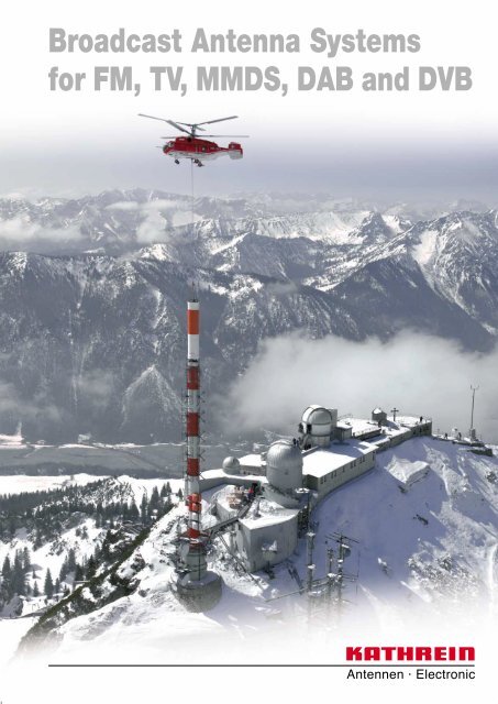
<strong>Broadcast</strong> <strong>Antenna</strong> <strong>Systems</strong><br />
for FM, TV, MMDS, DAB and DVB
Photo on title page: FM and TV Transmitting Station “Wendelstein”, during assembly the<br />
new DVB-T <strong>Antenna</strong> on 12th April 2005.<br />
Catalogue Issue 07/05<br />
Kathrein Plant IV near Rosenheim, Germany
Kathrein <strong>Broadcast</strong> <strong>Antenna</strong>s<br />
Kathrein is one of the world’s leading manufacturers of professional broadcast antenna<br />
systems, including a full range of transmitting antennas for FM, TV, MMDS, DAB and<br />
DVB broadcasting.<br />
KATHREIN-Werke KG was founded in 1919 in Rosenheim, Germany, to produce<br />
antennas and lightning protection equipment.<br />
Since the early 1960’s Kathrein has been supplying professional antenna systems of all<br />
sizes to broadcasters in every part of the world, from Canada to China and from Norway<br />
to South Africa.<br />
Right from the start Kathrein has maintained a high level of engineering capability.<br />
Today there is a team of antenna and mechanical engineers dealing exclusively with<br />
broadcast transmitting antennas.<br />
This highly qualified engineering team is responsible for:<br />
– Design of components (antennas, power splitters, etc.).<br />
– Design and optimization of complete antenna systems.<br />
– Installation and testing of antenna systems.<br />
– Project management.<br />
Kathrein can provide turn-key installations in cooperation with other contractors or using<br />
the customer’s installation personnel.<br />
Customers are welcome to take advantage of the technical expertise available from<br />
Kathrein and to discuss their specific requirements. If your needs cannot be met with<br />
our standard components we are prepared to develop special solutions for you.<br />
Kathrein’s quality management system is certified in accordance with ISO 9001, which<br />
includes not only all manufacturing operations, but also design processes.<br />
“Quality leads the way”<br />
As the world’s oldest and largest antenna manufacturer, we live up to our claim “Quality<br />
leads the way” on a daily basis. One of the fundamental principles is to always be on the<br />
lookout for the best solution for our customer.<br />
Our quality assurance system and our environmental management system apply to the<br />
entire company and are certified by TÜV according to EN ISO 9001 and EN ISO 14001.<br />
3
Please note:<br />
As a result of more stringent legal regulations and judgements regarding product<br />
liability, we are obliged to point out certain risks that may arise when products are<br />
used under extraordinary operating conditions.<br />
The mechanical design is based on the environmental conditions as stipulated in<br />
ETS 300 019-1-4, which include the static mechanical load imposed on an antenna by<br />
wind at maximum velocity.<br />
Extraordinary operating conditions, such as heavy icing or exceptional dynamic stress<br />
(e.g. strain caused by oscillating support structures), may result in the breakage of an<br />
antenna or even cause it to fall to the ground.<br />
These facts must be considered during the site planning process.<br />
4
Band I<br />
47 ... 88 MHz<br />
<strong>Antenna</strong> <strong>Systems</strong><br />
The antenna systems listed are<br />
examples of typical configurations.<br />
The mechanical and electrical data<br />
can be used to estimate gain, size<br />
and mechanical loads of a system.<br />
The final configuration and technical<br />
data of an individually designed<br />
antenna system, meeting the<br />
customer’s specific needs, will be<br />
determined by the Kathrein engineers.<br />
FM Band<br />
87.5 – 108 MHz<br />
Band III<br />
174 – 230 MHz<br />
UHF Band<br />
470 – 860 MHz<br />
MMDS<br />
2500 – 2700 MHz<br />
Relay Receiving <strong>Antenna</strong>s<br />
and Special <strong>Antenna</strong> <strong>Systems</strong><br />
<strong>Antenna</strong>s for TV<br />
47 ... 88 MHz<br />
<strong>Antenna</strong>s for FM<br />
66 – 73 MHz and 87.5 – 108 MHz<br />
<strong>Antenna</strong>s, Power Splitters and<br />
Accessories<br />
The basic antennas and related<br />
components shown in this catalog<br />
are only a small portion of the<br />
Kathrein broadcast product line.<br />
Many special versions are available,<br />
with different connectors, higher<br />
power ratings, and other features<br />
such as special probes or extra ice<br />
protection.<br />
Your enquiries are most welcome<br />
and we would like to discuss your<br />
special requirements.<br />
<strong>Antenna</strong>s for TV and DAB<br />
174 – 230 MHz<br />
<strong>Antenna</strong>s for TV and DVB<br />
470 – 860 MHz<br />
<strong>Antenna</strong>s for DAB<br />
1452 – 1492 MHz<br />
Power Splitters<br />
Further Components<br />
Technical Annex
<strong>Antenna</strong> <strong>Systems</strong><br />
47 ... 88 MHz<br />
47 ... 88 MHz
TV Transmitting <strong>Antenna</strong><br />
with dipole panels K 52 31 8..<br />
47 … 88 MHz<br />
● <strong>Antenna</strong> array of dipole panels K 52 31 8.. for different radiation patterns, especially suitable<br />
for mounting on square masts.<br />
● The feeder network is made up of coaxial power splitters and flexible connecting cables in<br />
accordance with the radiation patterns specification and the transmitting power.<br />
Input<br />
Frequency range<br />
VSWR<br />
Impedance<br />
Polarization<br />
Internal connections<br />
Max. power<br />
Vertical radiation pattern<br />
Horizontal radiation pattern<br />
Half antenna splitting<br />
Pressurization<br />
Painting<br />
Grounding<br />
Max. wind velocity<br />
Connectors according to IEC, EIA or DIN.<br />
One channel in Band I (47 … 88 MHz)<br />
s < 1.05 in one channel<br />
50 Ω<br />
Horizontal<br />
Connectors according to IEC, EIA or DIN<br />
are used throughout the system,<br />
allowing easy assembly and maintenance.<br />
According to customer’s requirements.<br />
Null fill and beam tilt upon request.<br />
Omnidirectional, directional or custom-designed.<br />
Upon request, the antenna can be divided into<br />
2 halves (for measurement and maintenance).<br />
The 2 halves are connected by a<br />
2-way power splitter or patch panel.<br />
Splitters and connecting cables can be supplied<br />
with dry air (please specify when ordering).<br />
If required, the antenna is painted in aviation<br />
warning colours.<br />
Via mounting parts.<br />
225 km/h<br />
H<br />
S<br />
No. of Panels Gain* Weight in kg (without mounting hardware) Windload in kN (160 km/h) <strong>Antenna</strong> height H in m (Spacing S in m)<br />
bays per in dB Frequency in MHz Frequency in MHz Frequency in MHz<br />
bay 47–54 54–61 60–68 66–72 76–82 82–88 47–54 54–61 60–68 66–72 76–82 82–88 47–54 54–61 60–68 66–72 76–82 82–88<br />
2 3 4 2 3 4 2 3 4<br />
2 3 4 5 6 2 3 4 5 6 2 3 4 5 6<br />
2 5.4 280 250 220 200 190 180 4.0 3.5 3.3 3.2 2.8 2.6<br />
1 3 3.5 450 400 350 320 300 300 6.0 5.3 5.0 4.8 4.2 3.9 4.5 4.0 3.6 3.3 2.9 2.7<br />
4 2.0 620 540 460 440 420 400 7.3 6.5 6.0 5.9 5.3 4.8<br />
2 8.4 620 540 460 440 420 400 8.0 7.0 6.5 6.3 5.6 5.2<br />
2 3 6.6 950 840 750 700 660 630 12.0 10.6 10.0 9.6 8.5 7.8 10.9 9.6 8.6 8.0 7.0 6.5<br />
4 5.0 1250 1100 970 900 850 800 14.5 13.0 12.0 11.8 10.5 9.5 (6.4) (5.6) (5.0) (4.7) (4.1) (3.8)<br />
2 11.5 1250 1100 970 900 850 800 16.0 14.0 13.0 12.6 11.2 10.4<br />
4 3 9.6 1750 1550 1480 1360 1300 1250 24.0 21.2 20.0 19.2 17.0 15.6 23.7 20.8 18.6 17.4 15.2 14.1<br />
4 8.1 2500 2200 1960 1800 1710 1630 29.0 26.0 24.0 23.6 21.0 19.0 (6.4) (5.6) (5.0) (4.7) (4.1) (3.8)<br />
2 13.3 1750 1550 1480 1360 1300 1250 24.1 21.0 19.5 18.9 16.8 15.6<br />
6 3 11.4 2770 2450 2200 2000 1900 1820 36.0 31.8 30.0 28.8 25.5 23.4 36.5 32.0 28.6 26.7 23.3 21.7<br />
4 9.9 3700 3260 2920 2700 2550 2420 43.6 39.0 36.0 35.4 31.5 28.5 (6.4) (5.6) (5.0) (4.7) (4.1) (3.8)<br />
2 14.5 2500 2200 1960 1800 1710 1630 32.1 28.0 26.0 25.2 22.4 20.8<br />
8 3 12.6 3700 3260 2920 2700 2550 2420 48.1 42.4 40.0 38.4 34.0 31.2 49.3 43.2 38.6 36.1 31.5 29.3<br />
4 11.1 4920 4350 3900 3560 3370 3200 58.1 52.0 48.0 47.2 42.0 38.0 (6.4) (5.6) (5.0) (4.7) (4.1) (3.8)<br />
* Referred to λ/2 dipole. Attenuation of the internal cabling and the gain-decrease<br />
in case of null fill in the vertical radiation pattern are not considered.<br />
Approximate values for gain decrease:<br />
cable attenuation: 0.2 – 0.5 dB<br />
null fill:<br />
0.3 – 1.0 dB<br />
Gain figures are valid for the direction of maximum radiation (see diagrams on<br />
following page).<br />
8
TV Transmitting <strong>Antenna</strong><br />
with dipole panels K 52 31 8..<br />
47 … 88 MHz<br />
Horizontal Radiation Patterns<br />
Examples of typical horizontal<br />
antenna arrays and their horizontal radiation patterns<br />
for minimal mast dimensions.<br />
Vertical Radiation Patterns<br />
Examples of typical vertical<br />
radiation patterns*) for several bays<br />
of identical, vertically stacked<br />
antenna arrays.<br />
Equal power splitting<br />
1,0<br />
2 bays<br />
E rel<br />
30 40<br />
0,5<br />
0 10 20 α°<br />
1,0<br />
4 bays<br />
10<br />
10<br />
3<br />
dB<br />
3<br />
dB<br />
E rel<br />
30 40<br />
0,5<br />
0 10 20 α°<br />
0<br />
0<br />
Equal power splitting<br />
Different power splitting<br />
4/10 P<br />
1,0<br />
6 bays<br />
E rel<br />
30 40<br />
1/10 P<br />
0,5<br />
1/10 P<br />
4/10 P<br />
0 10 20 α°<br />
1,0<br />
8 bays<br />
0,5<br />
10<br />
10<br />
3<br />
dB<br />
3<br />
dB<br />
E rel<br />
30 40<br />
0 10 20 α°<br />
0<br />
0<br />
*) without null fill<br />
with null fill and beam tilt<br />
9
TV Transmitting <strong>Antenna</strong><br />
with dipole panels K 52 34 8..<br />
47 … 88 MHz<br />
● <strong>Antenna</strong> array of dipole panels K 52 34 8.. for different radiation patterns, especially suitable<br />
for mounting on triangular or round masts.<br />
● The feeder network is made up of coaxial power splitters and flexible connecting cables in<br />
accordance with the radiation patterns specification and the transmitting power.<br />
Input<br />
Frequency range<br />
VSWR<br />
Impedance<br />
Polarization<br />
Internal connections<br />
Max. power<br />
Vertical radiation pattern<br />
Horizontal radiation pattern<br />
Half antenna splitting<br />
Pressurization<br />
Painting<br />
Grounding<br />
Max. wind velocity<br />
Connectors according to IEC, EIA or DIN.<br />
One channel in Band I (47 … 88 MHz)<br />
s < 1.05 in one channel<br />
50 Ω<br />
Horizontal<br />
Connectors according to IEC, EIA or DIN<br />
are used throughout the system,<br />
allowing easy assembly and maintenance.<br />
According to customer’s requirements.<br />
Null fill and beam tilt upon request.<br />
Omnidirectional, directional or custom-designed.<br />
Upon request, the antenna can be divided into<br />
2 halves (for measurement and maintenance).<br />
The 2 halves are connected by a<br />
2-way power splitter or patch panel.<br />
Splitters and connecting cables can be supplied<br />
with dry air (please specify when ordering).<br />
If required, the antenna is painted in aviation<br />
warning colours.<br />
Via mounting parts.<br />
225 km/h<br />
H<br />
S<br />
No. of Panels Gain* Weight in kg (without mounting hardware) Windload in kN (160 km/h) <strong>Antenna</strong> height H in m (Spacing S in m)<br />
bays per in dB Frequency in MHz Frequency in MHz Frequency in MHz<br />
bay 47–54 54–61 60–68 66–72 76–82 82–88 47–54 54–61 60–68 66–72 76–82 82–88 47–54 54–61 60–68 66–72 76–82 82–88<br />
2 3 4 2 3 4 2 3 4<br />
2 3 4 5 6 2 3 4 5 6 2 3 4 5 6<br />
1<br />
2 3.9 310 275 250 235 205 195 3.9 3.4 3.3 3.0 2.8 2.5 4.5 4.0 3.6 3.3 2.9 2.7<br />
3 1.7 470 410 375 350 310 290 5.7 5.1 4.8 4.4 4.1 3.8<br />
2<br />
2 6.9 650 550 500 470 410 390 7.9 6.7 6.5 6.0 5.5 5.0 10.9 9.6 8.6 8.0 7.0 6.5<br />
3 4.7 990 820 750 700 620 580 11.4 10.1 9.6 8.8 8.1 7.5 (6.4) (5.6) (5.0) (4.7) (4.1) (3.8)<br />
4<br />
2 9.9 1310 1095 1000 935 825 775 15.8 14.4 13.0 12.0 11.0 10.0 23.7 20.8 18.6 17.4 15.2 14.1<br />
3 7.7 1910 1645 1500 1405 1235 1165 22.8 20.2 19.2 17.6 16.2 15.0 (6.4) (5.6) (5.0) (4.7) (4.1) (3.8)<br />
6<br />
2 11.7 1910 1645 1500 1405 1235 1165 23.6 20.1 19.5 18.0 16.5 15.0 36.5 32.0 28.6 26.7 23.3 21.7<br />
3 9.5 2820 2645 2250 2105 1855 1745 31.5 30.3 28.8 26.4 24.3 22.5 (6.4) (5.6) (5.0) (4.7) (4.1) (3.8)<br />
8<br />
2 12.9 2600 2190 2000 1870 1650 1550 34.2 26.8 26.0 24.0 22.0 20.0 49.3 43.2 38.6 36.1 31.5 29.3<br />
3 10.7 3800 3290 3000 2810 2470 2330 45.6 40.4 38.4 35.2 32.4 30.0 (6.4) (5.6) (5.0) (4.7) (4.1) (3.8)<br />
* Referred to λ/2 dipole. Attenuation of the internal cabling and the gain-decrease<br />
in case of null fill in the vertical radiation pattern are not considered.<br />
Approximate values for gain decrease:<br />
cable attenuation: 0.2 – 0.5 dB<br />
null fill:<br />
0.3 – 1.0 dB<br />
Gain figures are valid for the direction of maximum radiation (see diagrams on<br />
following page).<br />
10
TV Transmitting <strong>Antenna</strong><br />
with dipole panels K 52 34 8..<br />
47 … 88 MHz<br />
Horizontal Radiation Patterns<br />
Examples of typical horizontal<br />
antenna arrays and their horizontal radiation patterns<br />
for minimal mast dimensions.<br />
Vertical Radiation Patterns<br />
Examples of typical vertical<br />
radiation patterns*) for several bays<br />
of identical, vertically stacked<br />
antenna arrays.<br />
Equal power splitting<br />
1,0<br />
2 bays<br />
E rel<br />
30 40<br />
0,5<br />
60°<br />
0 10 20 α°<br />
1,0<br />
4 bays<br />
10<br />
10<br />
3<br />
dB<br />
3<br />
dB<br />
E rel<br />
30 40<br />
0,5<br />
0 10 20 α°<br />
0<br />
0<br />
Different power splitting<br />
3/4 P<br />
3/7 P<br />
1,0<br />
6 bays<br />
E rel<br />
30 40<br />
60°<br />
0,5<br />
1/7 P<br />
0 10 20 α°<br />
1/4 P<br />
3/7 P<br />
1,0<br />
8 bays<br />
0,5<br />
10<br />
10<br />
3<br />
dB<br />
3<br />
dB<br />
E rel<br />
30 40<br />
0 10 20 α°<br />
0<br />
0<br />
*) without null fill<br />
with null fill and beam tilt<br />
11
<strong>Antenna</strong> <strong>Systems</strong><br />
87.5 – 108 MHz<br />
87.5 – 108 MHz
FM Transmitting <strong>Antenna</strong><br />
with dipole panels K 52 31 1. .<br />
87.5 – 108 MHz<br />
● <strong>Antenna</strong> array of dipole panels K 52 31 18 7 for different radiation patterns, especially suitable<br />
for mounting on square masts.<br />
● The feeder network is made up of coaxial power splitters and flexible connecting cables in<br />
accordance with the radiation patterns specification and the transmitting power.<br />
Input<br />
Frequency range<br />
VSWR<br />
Impedance<br />
Polarization<br />
Internal connections<br />
Max. power<br />
Vertical radiation pattern<br />
Horizontal radiation pattern<br />
Half antenna splitting<br />
Pressurization<br />
Painting<br />
Grounding<br />
Max. wind velocity<br />
Connectors according to IEC, EIA or DIN.<br />
87.5 – 108 MHz<br />
s < 1.2 throughout the whole frequency range.<br />
Lower VSWR for single channels upon request.<br />
50 Ω<br />
Horizontal or vertical<br />
Connectors according to IEC, EIA or DIN<br />
are used throughout the system,<br />
allowing easy assembly and maintenance.<br />
According to customer’s requirements.<br />
Null fill and beam tilt upon request.<br />
Omnidirectional, directional or custom-designed.<br />
Upon request, the antenna can be divided into<br />
2 halves (for measurement and maintenance).<br />
The 2 halves are connected by a<br />
2-way power splitter or patch panel.<br />
Splitters and connecting cables can be supplied<br />
with dry air (please specify when ordering).<br />
If required, the antenna is painted in aviation<br />
warning colours.<br />
Via mounting parts.<br />
225 km/h<br />
H<br />
3200 mm<br />
No. Panels Gain* Weight <strong>Antenna</strong> Windload<br />
of per (at mid-band) (without mounting height H (v = 160 km/h)<br />
bays bay dB times hardware) kg m kN<br />
2 5.0 3.2 140 2.7<br />
1 3 3.5 2.2 200 2.5 4.0<br />
4 2.0 1.6 260 4.7<br />
2 8.0 6.3 260 5.5<br />
2 3 6.5 4.5 400 5.7 8.0<br />
4 5.0 3.2 530 9.5<br />
2 11.0 12.6 530 11.0<br />
4 3 9.5 8.9 790 12.1 16.0<br />
4 8.0 6.3 1080 19.0<br />
2 12.8 19.1 790 16.5<br />
6 3 11.3 13.0 1200 18.5 24.0<br />
4 9.7 9.3 1610 28.5<br />
2 14.0 25.1 1080 22.0<br />
8 3 12.5 17.8 1610 24.9 32.0<br />
4 11.0 12.6 2150 38.0<br />
* Referred to λ/2 dipole. Attenuation of the internal cabling and the gain-decrease<br />
in case of null fill in the vertical radiation pattern are not considered.<br />
Approximate values for gain decrease:<br />
cable attenuation: 0.2 – 0.5 dB<br />
null fill:<br />
0.3 – 1.0 dB<br />
Gain figures are valid for the direction of maximum radiation (see diagrams on<br />
following page).<br />
14
FM Transmitting <strong>Antenna</strong><br />
with dipole panels K 52 31 1. .<br />
87.5 – 108 MHz<br />
Horizontal Radiation Patterns<br />
Examples of typical horizontal<br />
antenna arrays and their horizontal radiation patterns<br />
for minimal mast dimensions.<br />
Vertical Radiation Patterns<br />
Examples of typical vertical<br />
radiation patterns*) for several bays<br />
of identical, vertically stacked<br />
antenna arrays.<br />
Equal power splitting<br />
1,0<br />
2 bays<br />
E rel<br />
30 40<br />
0,5<br />
0 10 20 α°<br />
1,0<br />
4 bays<br />
10<br />
10<br />
3<br />
dB<br />
3<br />
dB<br />
E rel<br />
30 40<br />
0,5<br />
0 10 20 α°<br />
0<br />
0<br />
Equal power splitting<br />
Different power splitting<br />
4/10 P<br />
1,0<br />
6 bays<br />
E rel<br />
30 40<br />
1/10 P<br />
0,5<br />
4/10 P<br />
0 10 20 α°<br />
1/10 P<br />
1,0<br />
8 bays<br />
E rel<br />
30 40<br />
0,5<br />
10<br />
10<br />
3<br />
0<br />
dB<br />
3<br />
0<br />
dB<br />
0 10 20 α°<br />
*) without null fill<br />
with null fill and beam tilt<br />
15
FM Transmitting <strong>Antenna</strong><br />
with dipole panels K 52 34 1.<br />
87.5 – 108 MHz<br />
● <strong>Antenna</strong> array of dipole panels K 52 34 17 for different radiation patterns, especially suitable<br />
for mounting on triangular or round masts.<br />
● The feeder network is made up of coaxial power splitters and flexible connecting cables in<br />
accordance with the radiation patterns specification and the transmitting power.<br />
Input<br />
Frequency range<br />
VSWR<br />
Impedance<br />
Polarization<br />
Internal connections<br />
Max. power<br />
Vertical radiation pattern<br />
Horizontal radiation pattern<br />
Half antenna splitting<br />
Pressurization<br />
Painting<br />
Grounding<br />
Max. wind velocity<br />
Connectors according to IEC, EIA or DIN.<br />
87.5 – 108 MHz<br />
s < 1.2 throughout the whole frequency range.<br />
Lower VSWR for single channels upon request.<br />
50 Ω<br />
Horizontal<br />
Connectors according to IEC, EIA or DIN<br />
are used throughout the system,<br />
allowing easy assembly and maintenance.<br />
According to customer’s requirements.<br />
Null fill and beam tilt upon request.<br />
Omnidirectional, directional or custom-designed.<br />
Upon request, the antenna can be divided into<br />
2 halves (for measurement and maintenance).<br />
The 2 halves are connected by a<br />
2-way power splitter or patch panel.<br />
Splitters and connecting cables can be supplied<br />
with dry air (please specify when ordering).<br />
If required, the antenna is painted in aviation<br />
warning colours.<br />
Via mounting parts.<br />
225 km/h<br />
H<br />
3200 mm<br />
No. Panels Gain* Weight <strong>Antenna</strong> Windload<br />
of per (at mid-band) (without mounting height H (v = 160 km/h)<br />
bays bay dB times hardware) kg m kN<br />
1<br />
2<br />
4<br />
6<br />
8<br />
2 3.9 2.5 150 3.0<br />
3 1.7 1.5 220<br />
2.5<br />
4.2<br />
2 6.9 4.9 290 6.0<br />
3 4.7 3.0 420<br />
5.7<br />
8.4<br />
2 9.9 9.8 560 12.0<br />
3 7.7 5.9 850<br />
12.1<br />
16.8<br />
2 11.7 14.8 850 18.0<br />
3 9.5 8.9 1290<br />
18.5<br />
25.2<br />
2 12.9 19.5 1150 24.0<br />
3 10.7 11.7 1700<br />
24.9<br />
33.6<br />
* Referred to λ/2 dipole. Attenuation of the internal cabling and the gain-decrease<br />
in case of null fill in the vertical radiation pattern are not considered.<br />
Approximate values for gain decrease:<br />
cable attenuation: 0.2 – 0.5 dB<br />
null fill:<br />
0.3 – 1.0 dB<br />
Gain figures are valid for the direction of maximum radiation (see diagrams on<br />
following page).<br />
16
FM Transmitting <strong>Antenna</strong><br />
with dipole panels K 52 34 1.<br />
87.5 – 108 MHz<br />
Horizontal Radiation Patterns<br />
Examples of typical horizontal<br />
antenna arrays and their horizontal radiation patterns<br />
for minimal mast dimensions.<br />
Vertical Radiation Patterns<br />
Examples of typical vertical<br />
radiation patterns*) for several bays<br />
of identical, vertically stacked<br />
antenna arrays.<br />
Equal power splitting<br />
1,0<br />
2 bays<br />
E rel<br />
30 40<br />
0,5<br />
60°<br />
0 10 20 α°<br />
1,0<br />
4 bays<br />
10<br />
10<br />
3<br />
dB<br />
3<br />
dB<br />
E rel<br />
30 40<br />
0,5<br />
0 10 20 α°<br />
0<br />
0<br />
Different power splitting<br />
3/4 P<br />
3/7 P<br />
1,0<br />
6 bays<br />
E rel<br />
30 40<br />
60°<br />
0,5<br />
1/7 P<br />
0 10 20 α°<br />
1/4 P<br />
3/7 P<br />
1,0<br />
8 bays<br />
E rel<br />
30 40<br />
0,5<br />
10<br />
10<br />
3<br />
0<br />
dB<br />
3<br />
0<br />
dB<br />
0 10 20 α°<br />
*) without null fill<br />
with null fill and beam tilt<br />
17
FM Transmitting <strong>Antenna</strong><br />
with dipole panels K 53 32 1. .<br />
87.5 – 108 MHz<br />
● <strong>Antenna</strong> array of circularly polarized dipole panels K 53 32 18 7 for different radiation patterns,<br />
especially suitable for mounting on square masts.<br />
● The feeder network is made up of coaxial power splitters and flexible connecting cables<br />
in accordance with the radiation patterns specification and the transmitting power.<br />
Input<br />
Frequency range<br />
VSWR<br />
Impedance<br />
Polarization<br />
Internal connections<br />
Max. power<br />
Vertical radiation pattern<br />
Horizontal radiation pattern<br />
Half antenna splitting<br />
Pressurization<br />
Painting<br />
Grounding<br />
Max. wind velocity<br />
Connectors according to IEC, EIA or DIN.<br />
87.5 – 108 MHz<br />
s < 1.2 throughout the whole frequency range.<br />
Lower VSWR for single channels upon request.<br />
50 Ω<br />
Linear, circular or elliptical<br />
Connectors according to IEC, EIA or DIN<br />
are used throughout the system,<br />
allowing easy assembly and maintenance.<br />
According to customer’s requirements.<br />
Null fill and beam tilt upon request.<br />
Omnidirectional, directional or custom-designed.<br />
Upon request, the antenna can be divided into<br />
2 halves (for measurement and maintenance).<br />
The 2 halves are connected by a<br />
2-way power splitter or patch panel.<br />
Splitters and connecting cables can be supplied<br />
with dry air (please specify when ordering).<br />
If required, the antenna is painted in aviation<br />
warning colours.<br />
Via mounting parts.<br />
225 km/h<br />
H<br />
3000 mm<br />
No. Panels Gain* Weight <strong>Antenna</strong> Windload<br />
of per (at mid-band) (without mounting height H (v = 160 km/h)<br />
bays bay dB times hardware) kg m kN<br />
2 2.0 1.6 200 2.75<br />
1 3 0.5 1.1 320 2.2 4.35<br />
4 –1.0 0.8 420 5.5<br />
2 5.0 3.2 420 5.5<br />
2 3 3.5 2.4 750 5.2 8.7<br />
4 2.0 1.6 850 11.0<br />
2 8.0 6.3 850 11.0<br />
4 3 6.5 4.5 1530 11.2 17.4<br />
4 5.0 3.2 1660 22.0<br />
2 9.8 9.6 1530 16.5<br />
6 3 8.3 6.8 1870 17.2 26.1<br />
4 6.7 4.7 2240 33.0<br />
2 11.0 12.6 1660 22.0<br />
8 3 9.5 8.9 2240 23.2 34.8<br />
4 8.0 6.3 2970 44.0<br />
* Referred to λ/2 dipole. Attenuation of the internal cabling and the gain-decrease<br />
in case of null fill in the vertical radiation pattern are not considered.<br />
Approximate values for gain decrease:<br />
cable attenuation: 0.2 – 0.5 dB<br />
null fill:<br />
0.3 – 1.0 dB<br />
Gain figures are valid for the direction of maximum radiation (see diagrams on<br />
following page).<br />
18
FM Transmitting <strong>Antenna</strong><br />
with dipole panels K 53 32 1. .<br />
87.5 – 108 MHz<br />
Horizontal Radiation Patterns<br />
Examples of typical horizontal<br />
antenna arrays and their horizontal radiation patterns<br />
for minimal mast dimensions.<br />
Vertical Radiation Patterns<br />
Examples of typical vertical<br />
radiation patterns*) for several bays<br />
of identical, vertically stacked<br />
antenna arrays.<br />
Equal power splitting<br />
1,0<br />
2 bays<br />
E rel<br />
30 40<br />
0,5<br />
0 10 20 α°<br />
1,0<br />
4 bays<br />
10<br />
10<br />
3<br />
dB<br />
3<br />
dB<br />
E rel<br />
30 40<br />
0,5<br />
0 10 20 α°<br />
0<br />
0<br />
Equal power splitting<br />
Different power splitting<br />
4/10 P<br />
1,0<br />
6 bays<br />
E rel<br />
30 40<br />
4/10 P<br />
0,5<br />
1/10 P<br />
1/10 P<br />
0 10 20 α°<br />
1,0<br />
8 bays<br />
E rel<br />
30 40<br />
0,5<br />
10<br />
10<br />
3<br />
0<br />
dB<br />
3<br />
0<br />
dB<br />
0 10 20 α°<br />
*) without null fill<br />
with null fill and beam tilt<br />
19
FM Transmitting <strong>Antenna</strong><br />
with dipole panels 754 154<br />
87.5 – 108 MHz<br />
● <strong>Antenna</strong> array of circularly polarized dipole panels 754 154 for different radiation patterns,<br />
especially suitable for mounting on triangular or round masts.<br />
● The feeder network is made up of coaxial power splitters and flexible connecting cables<br />
in accordance with the radiation patterns specification and the transmitting power.<br />
Input<br />
Frequency range<br />
VSWR<br />
Impedance<br />
Polarization<br />
Internal connections<br />
Max. power<br />
Vertical radiation pattern<br />
Horizontal radiation pattern<br />
Half antenna splitting<br />
Pressurization<br />
Painting<br />
Grounding<br />
Max. wind velocity<br />
Connectors according to IEC, EIA or DIN.<br />
87.5 – 108 MHz<br />
s < 1.2 throughout the whole frequency range.<br />
Lower VSWR for single channels upon request.<br />
50 Ω<br />
Circular<br />
Connectors according to IEC, EIA or DIN<br />
are used throughout the system,<br />
allowing easy assembly and maintenance.<br />
According to customer’s requirements.<br />
Null fill and beam tilt upon request.<br />
Omnidirectional, directional or custom-designed.<br />
Upon request, the antenna can be divided into<br />
2 halves (for measurement and maintenance).<br />
The 2 halves are connected by a<br />
2-way power splitter or patch panel.<br />
Splitters and connecting cables can be supplied<br />
with dry air (please specify when ordering).<br />
If required, the antenna is painted in aviation<br />
warning colours.<br />
Via mounting parts.<br />
225 km/h<br />
H<br />
3000 mm<br />
No. Panels Gain* Weight <strong>Antenna</strong> Windload<br />
of per (at mid-band) (without mounting height H (v = 160 km/h)<br />
bays bay dB times hardware) kg m kN<br />
1<br />
2<br />
4<br />
6<br />
8<br />
2 0.0 1.0 140 2.4<br />
3 –2.0 0.6 200<br />
1.82<br />
3.5<br />
2 3.1 2.0 260 4.8<br />
3 1.1 1.3 430<br />
4.82<br />
7.0<br />
2 6.2 4.2 580 9.6<br />
3 4.2 2.6 800<br />
10.82<br />
14.0<br />
2 8.1 6.5 800 14.4<br />
3 6.1 4.1 1230<br />
16.82<br />
21.0<br />
2 9.3 8.5 1100 19.2<br />
3 7.3 5.4 1590<br />
22.82<br />
28.0<br />
* Referred to λ/2 dipole. Attenuation of the internal cabling and the gain-decrease<br />
in case of null fill in the vertical radiation pattern are not considered.<br />
Approximate values for gain decrease:<br />
cable attenuation: 0.2 – 0.5 dB<br />
null fill:<br />
0.3 – 1.0 dB<br />
Gain figures are valid for the direction of maximum radiation (see diagrams on<br />
following page).<br />
20
FM Transmitting <strong>Antenna</strong><br />
with dipole panels 754 154<br />
87.5 – 108 MHz<br />
Horizontal Radiation Patterns<br />
Examples of typical horizontal<br />
antenna arrays and their horizontal radiation patterns<br />
for minimal mast dimensions.<br />
Vertical Radiation Patterns<br />
Examples of typical vertical<br />
radiation patterns*) for several bays<br />
of identical, vertically stacked<br />
antenna arrays.<br />
Equal power splitting<br />
1,0<br />
2 bays<br />
E rel<br />
30 40<br />
0,5<br />
60°<br />
0 10 20 α°<br />
1,0<br />
4 bays<br />
10<br />
10<br />
3<br />
dB<br />
3<br />
dB<br />
E rel<br />
30 40<br />
0,5<br />
0 10 20 α°<br />
0<br />
0<br />
Different power splitting<br />
3/4P<br />
3/7P<br />
1,0<br />
6 bays<br />
E rel<br />
30 40<br />
60°<br />
0,5<br />
1/4P<br />
1/7P<br />
0 10 20 α°<br />
3/7P<br />
1,0<br />
8 bays<br />
E rel<br />
30 40<br />
0,5<br />
10<br />
10<br />
3<br />
0<br />
dB<br />
3<br />
0<br />
dB<br />
0 10 20 α°<br />
*) without null fill<br />
with null fill and beam tilt<br />
21
FM Transmitting <strong>Antenna</strong><br />
(Superturnstile <strong>Antenna</strong>) 87.5 – 108 MHz<br />
K 52 97 1. .<br />
● Self-supporting hot-dip galvanized steel superturnstile antenna. Up to 4 bays may be stacked.<br />
● Optionally up to 8 bays may be stacked if the superturnstile antennas are mounted inside a<br />
self-supporting fiberglass cylinder.<br />
Input<br />
Frequency range<br />
VSWR<br />
Impedance<br />
Polarization<br />
Max. power<br />
Vertical radiation pattern<br />
Horizontal radiation pattern<br />
Half antenna splitting<br />
Internal connections<br />
Structure<br />
Mounting<br />
Ice protection<br />
Grounding<br />
Max. wind velocity<br />
Connectors according to IEC, EIA or DIN.<br />
87.5 – 108 MHz<br />
s < 1.2 throughout the whole frequency range.<br />
Tuning not required.<br />
50 Ω<br />
Horizontal<br />
According to customer’s requirements,<br />
10 kW max. per bay.<br />
Null fill and beam tilt upon request.<br />
Omnidirectional<br />
Upon request, the antenna can be divided into<br />
2 halves (for measurement and maintenance).<br />
The 2 halves are connected by a<br />
2-way power splitter or patch panel.<br />
The radiating elements are fed with<br />
coaxial connecting cables and hybrid couplers.<br />
Connectors according to IEC, EIA or DIN<br />
are used throughout the system,<br />
allowing easy assembly and maintenance.<br />
Superturnstile antenna on self-supporting<br />
hot dip galvanized steel structure.<br />
Up to 4 bays may be stacked.<br />
On top of existing structure by means of a flange.<br />
Under icing the fiberglass cover over<br />
the feedslots and the rugged construction keep<br />
the antenna in proper function.<br />
Via mounting parts.<br />
160 km/h<br />
H<br />
3000 mm<br />
No. Type No. / Gain* Weight <strong>Antenna</strong> Windload<br />
of Order No. (at mid-band) (without cylinder) height H (without cylinder)<br />
bays dB times kg m (160 km/h) kN<br />
1 K 52 97 11 1 1.26 275 3 3.2<br />
2 K 52 97 12 4 2.51 550 6 6.5<br />
4 K 52 97 14 7 5.00 1450 12 15.0<br />
* Referred to λ/2 dipole. Attenuation of the internal cabling and the gain-decrease<br />
in case of null fill in the vertical radiation pattern are not considered.<br />
Approximate values for gain decrease:<br />
cable attenuation: 0.2 – 0.4 dB<br />
null fill:<br />
0.3 – 1.0 dB<br />
Gain figures are valid for the direction of maximum radiation (see diagrams on<br />
following page).<br />
22
FM Transmitting <strong>Antenna</strong><br />
(Superturnstile <strong>Antenna</strong>) 87.5 – 108 MHz<br />
K 52 97 1. .<br />
Typical Horizontal Radiation Pattern<br />
(at mid-band)<br />
Vertical Radiation Patterns<br />
Examples of typical vertical<br />
radiation patterns*) for several bays<br />
of identical, vertically stacked<br />
antenna arrays.<br />
100<br />
1 bay<br />
E rel<br />
30 40<br />
50<br />
10<br />
3<br />
0<br />
dB<br />
0 10 20 α°<br />
100<br />
2 bays<br />
E rel<br />
30 40<br />
50<br />
0 10 20 α°<br />
100<br />
4 bays<br />
E rel<br />
30 40<br />
50<br />
0 10 20 α°<br />
*) without null fill<br />
with null fill and beam tilt<br />
23
<strong>Antenna</strong> <strong>Systems</strong><br />
174 – 230 MHz<br />
174 – 230 MHz
TV Transmitting <strong>Antenna</strong><br />
with dipole panels K 52 33 5. .<br />
174 – 230 MHz<br />
● <strong>Antenna</strong> array of dipole panels K 52 33 57 for different radiation patterns, especially suitable<br />
for mounting on square masts.<br />
● The feeder network is made up of coaxial power splitters and flexible connecting cables in<br />
accordance with the radiation patterns specification and the transmitting power.<br />
Input<br />
Connectors according to IEC, EIA or DIN.<br />
Frequency range<br />
174 – 230 MHz<br />
VSWR<br />
< 1.05 in the operating channels after tuning.<br />
Impedance<br />
50 Ω<br />
Polarization Horizontal. Application of panels K 53 33 57<br />
allows vertical polarization as well.<br />
Internal connections<br />
Connectors according to IEC, EIA or DIN<br />
are used throughout the system,<br />
allowing easy assembly and maintenance.<br />
Max. power<br />
According to customer’s requirements.<br />
Vertical radiation pattern<br />
Null fill and beam tilt upon request.<br />
Horizontal radiation pattern Omnidirectional, directional or custom-designed.<br />
Half antenna splitting Upon request, the antenna can be divided into<br />
2 halves (for measurement and maintenance).<br />
The 2 halves are connected by a<br />
2-way power splitter or patch panel.<br />
Pressurization<br />
Splitters and connecting cables can be supplied<br />
with dry air (please specify when ordering).<br />
Painting<br />
If required, the antenna is painted in aviation<br />
warning colours.<br />
Grounding<br />
Via mounting parts.<br />
Max. wind velocity<br />
225 km/h<br />
H<br />
3200 mm<br />
No. Panels Gain* Weight <strong>Antenna</strong> Windload<br />
of per (at mid-band) (without mounting height H (v = 160 km/h)<br />
bays bay dB times hardware) kg m kN<br />
2 9.0 7.9 130 2.5<br />
1 3 7.6 5.8 195 2.8 3.75<br />
4 6.1 4.1 270 5.0<br />
2 11.8 15.1 270 5.0<br />
2 3 10.4 11.0 390 6.0 7.5<br />
4 8.9 7.8 540 10.0<br />
2 14.7 29.5 540 10.0<br />
4 3 13.3 21.4 780 12.4 15.0<br />
4 11.8 15.1 1080 20.0<br />
2 16.4 43.7 810 15.0<br />
6 3 15.0 31.6 1170 18.8 22.5<br />
4 13.5 22.4 1640 30.0<br />
2 17.6 57.5 1080 20.0<br />
8 3 16.2 41.7 1640 25.2 30.0<br />
4 14.7 29.5 2160 40.0<br />
* Referred to λ/2 dipole. Attenuation of the internal cabling and the gain-decrease<br />
in case of null fill in the vertical radiation pattern are not considered.<br />
Approximate values for gain decrease:<br />
cable attenuation: 0.2 – 0.5 dB<br />
null fill:<br />
0.3 – 1.0 dB<br />
Gain figures are valid for the direction of maximum radiation (see diagrams on<br />
following page).<br />
26
TV Transmitting <strong>Antenna</strong><br />
with dipole panels K 52 33 5. .<br />
174 – 230 MHz<br />
Horizontal Radiation Patterns<br />
Examples of typical horizontal<br />
antenna arrays and their horizontal radiation patterns<br />
for minimal mast dimensions.<br />
Vertical Radiation Patterns<br />
Examples of typical vertical<br />
radiation patterns*) for several bays<br />
of identical, vertically stacked<br />
antenna arrays.<br />
Equal power splitting<br />
100<br />
2 bays<br />
E rel<br />
100<br />
50<br />
0 5 10 α°<br />
10<br />
3<br />
0<br />
dB<br />
Equal power splitting<br />
10<br />
3<br />
0<br />
dB<br />
Different power splitting<br />
4/13 P<br />
1/13 P<br />
4/13 P<br />
4/13 P<br />
4 bays<br />
100<br />
E rel<br />
50<br />
0 5 10 α°<br />
6 bays<br />
100<br />
E rel<br />
50<br />
0 5 10 α°<br />
8 bays<br />
E rel<br />
50<br />
10<br />
10<br />
3<br />
0<br />
dB<br />
3<br />
0<br />
dB<br />
0 5 10 α°<br />
*) without null fill<br />
with null fill and beam tilt<br />
27
TV Transmitting <strong>Antenna</strong><br />
with dipole panels K 52 34 5. .<br />
174 ... 230 MHz<br />
● <strong>Antenna</strong> array of dipole panels K 52 34 5.. for different radiation patterns, especially suitable<br />
for mounting on triangular or round masts.<br />
● The feeder network is made up of coaxial power splitters and flexible connecting cables in<br />
accordance with the radiation patterns specification and the transmitting power.<br />
Input<br />
Frequency range<br />
VSWR<br />
Impedance<br />
Polarization<br />
Internal connections<br />
Max. power<br />
Vertical radiation pattern<br />
Horizontal radiation pattern<br />
Half antenna splitting<br />
Pressurization<br />
Painting<br />
Grounding<br />
Max. wind velocity<br />
Connectors according to IEC, EIA or DIN.<br />
174 – 202 MHz resp. 202 – 230 MHz<br />
< 1.05 in the operating channels after tuning.<br />
50 Ω<br />
Horizontal<br />
Connectors according to IEC, EIA or DIN<br />
are used throughout the system,<br />
allowing easy assembly and maintenance.<br />
According to customer’s requirements.<br />
Null fill and beam tilt upon request.<br />
Omnidirectional, directional or custom-designed.<br />
Upon request, the antenna can be divided into<br />
2 halves (for measurement and maintenance).<br />
The 2 halves are connected by a<br />
2-way power splitter or patch panel.<br />
Splitters and connecting cables can be supplied<br />
with dry air (please specify when ordering).<br />
If required, the antenna is painted in aviation<br />
warning colours.<br />
Via mounting parts.<br />
225 km/h<br />
H<br />
1600 mm<br />
No. Panels Gain* Weight <strong>Antenna</strong> Windload<br />
of per (at mid-band) (without mounting height H (v = 160 km/h)<br />
bays bay dB times hardware) kg m kN<br />
1<br />
2<br />
4<br />
6<br />
8<br />
2 3.9 2.5 50 0.9<br />
3 1.7 1.5 70<br />
1.2<br />
1.25<br />
2 6.9 4.9 95 1.8<br />
3 4.7 3.0 140<br />
2.8<br />
2.5<br />
2 9.9 9.8 180 3.6<br />
3 7.7 5.9 270<br />
6.0<br />
5.0<br />
2 11.7 14.8 270 5.4<br />
3 9.5 8.9 400<br />
9.2<br />
7.5<br />
2 12.9 19.5 360 7.2<br />
3 10.7 11.7 540<br />
12.4<br />
10.0<br />
* Referred to λ/2 dipole. Attenuation of the internal cabling and the gain-decrease<br />
in case of null fill in the vertical radiation pattern are not considered.<br />
Approximate values for gain decrease:<br />
cable attenuation: 0.2 – 0.5 dB<br />
null fill:<br />
0.3 – 1.0 dB<br />
Gain figures are valid for the direction of maximum radiation (see diagrams on<br />
following page).<br />
28
TV Transmitting <strong>Antenna</strong><br />
with dipole panels K 52 34 5. .<br />
174 ... 230 MHz<br />
Horizontal Radiation Patterns<br />
Examples of typical horizontal<br />
antenna arrays and their horizontal radiation patterns<br />
for minimal mast dimensions.<br />
Vertical Radiation Patterns<br />
Examples of typical vertical<br />
radiation patterns*) for several bays<br />
of identical, vertically stacked<br />
antenna arrays.<br />
Equal power splitting<br />
1,0<br />
2 bays<br />
E rel<br />
30 40<br />
0,5<br />
60°<br />
0 10 20 α°<br />
1,0<br />
4 bays<br />
E rel<br />
30 40<br />
0,5<br />
10<br />
10<br />
3<br />
0<br />
dB<br />
3<br />
0<br />
dB<br />
0 10 20 α°<br />
3/4 P<br />
Different power splitting<br />
3/7 P<br />
1,0<br />
6 bays<br />
E rel<br />
30 40<br />
60°<br />
0,5<br />
1/7 P<br />
0 10 20 α°<br />
1/4 P<br />
3/7 P<br />
1,0<br />
8 bays<br />
E rel<br />
30 40<br />
0,5<br />
10<br />
10<br />
3<br />
0<br />
dB<br />
3<br />
0<br />
dB<br />
0 10 20 α°<br />
*) without null fill<br />
with null fill and beam tilt<br />
29
TV Transmitting <strong>Antenna</strong><br />
(Superturnstile <strong>Antenna</strong>) 174 – 230 MHz<br />
K 52 97 5. .<br />
● Superturnstile <strong>Antenna</strong> made of hot-dip galvanized steel for mounting on top of mast.<br />
● Up to 4 bays may be built as self-supporting version. Up to 16 bays can be stacked<br />
inside a self-supporting G.R.P. cylinder.<br />
Input<br />
Frequency range<br />
VSWR<br />
Impedance<br />
Polarization<br />
Max. power<br />
Vertical radiation pattern<br />
Horizontal radiation pattern<br />
Half antenna splitting<br />
Internal connections<br />
Mounting<br />
Ice protection<br />
Grounding<br />
Max. wind velocity<br />
Connectors according to IEC, EIA or DIN.<br />
174 – 230 MHz<br />
< 1.05 in the operating channel<br />
50 Ω<br />
Horizontal<br />
According to customer’s requirements,<br />
10 kW max. per bay.<br />
Null fill and beam tilt upon request.<br />
Omnidirectional<br />
Upon request, the antenna can be divided into<br />
2 halves (for measurement and maintenance).<br />
The 2 halves are connected by a<br />
2-way power splitter or patch panel.<br />
The radiating elements are fed with<br />
coaxial connecting cables and hybrid couplers.<br />
Connectors according to IEC, EIA or DIN<br />
are used throughout the system,<br />
allowing easy assembly and maintenance.<br />
On top of existing structure by means of a flange.<br />
The radiating slots are protected by a fiberglass<br />
cover. Cylinder provides full protection.<br />
Via mounting parts resp. via 4 grounding ropes<br />
at the exterior cylinder-surface.<br />
As required.<br />
H<br />
1500 mm<br />
∅ 1.6 m<br />
G.R.P. cylinder<br />
30<br />
No. Gain* Weight kg <strong>Antenna</strong> Windload<br />
of (at mid-band) without with height H (v = 160 km/h)<br />
bays dB times cylinder cylinder m kN<br />
2 4.0 2.5 150 depending 3.0 4.0<br />
4 7.0 5.0 310 on 6.0 8.0<br />
8 10.0 10.0 660 fiber- 12.0 16.0<br />
12 11.8 15.1 1010 glass- 18.0 24.0<br />
16 13.0 20.0 1360 cylinder 24.0 34.0<br />
Wind load with cylinder<br />
* Referred to λ/2 dipole. Attenuation of the internal cabling and the gain-decrease<br />
in case of null fill in the vertical radiation pattern are not considered.<br />
Approximate values for gain decrease:<br />
cable attenuation: 0.2 – 0.5 dB<br />
null fill:<br />
0.3 – 1.0 dB<br />
Gain figures are valid for the direction of maximum radiation (see diagrams on<br />
following page).
TV Transmitting <strong>Antenna</strong><br />
(Superturnstile <strong>Antenna</strong>) 174 – 230 MHz<br />
K 52 97 5. .<br />
Typical Horizontal Radiation Pattern<br />
(at mid-band)<br />
Vertical Radiation Patterns<br />
Examples of typical vertical<br />
radiation patterns*) for several bays<br />
of identical, vertically stacked<br />
antenna arrays.<br />
100<br />
2 bays<br />
E rel<br />
30 40<br />
50<br />
10<br />
3<br />
dB<br />
0 10 20 α°<br />
0<br />
100<br />
4 bays<br />
E rel<br />
30 40<br />
50<br />
0 10 20<br />
α°<br />
100<br />
8 bays<br />
E rel<br />
30 40<br />
50<br />
0 10 20<br />
α°<br />
100<br />
12 bays<br />
E rel<br />
30 40<br />
50<br />
0 10 20<br />
α°<br />
*) without null fill<br />
with null fill and beam tilt<br />
31
TV Transmitting <strong>Antenna</strong><br />
with dipole panels K 52 30 5. . or K 52 31 5. .<br />
174 – 230 MHz<br />
● Typical antenna array with dipole panels K 52 30 57 or K 52 31 57.<br />
● The feeder network is made up of coaxial power splitters and flexible connecting cables<br />
in accordance with the radiation patterns specification and the transmitting power.<br />
Input<br />
Frequency range<br />
VSWR<br />
Impedance<br />
Polarization<br />
Internal connections<br />
Max. power<br />
Radiation pattern<br />
Half antenna splitting<br />
Pressurization<br />
Grounding<br />
Max. wind velocity<br />
Connectors according to IEC, EIA or DIN.<br />
174 – 230 MHz<br />
< 1.05 in the operating channel after tuning<br />
or < 1.1 in the whole range<br />
50 Ω<br />
Horizontal or vertical<br />
Connectors according to IEC, EIA or DIN<br />
are used throughout the system,<br />
allowing easy assembly and maintenance.<br />
According to customer’s requirements.<br />
The examples of radiation patterns are valid<br />
for horizontal polarization.<br />
At vertical polarization patterns vary slightly.<br />
Upon request, the antenna can be divided into<br />
2 halves (for measurement and maintenance).<br />
The 2 halves are connected by a<br />
2-way power splitter or patch panel.<br />
Splitters and connecting cables can be supplied<br />
with dry air (please specify when ordering).<br />
Via mounting parts.<br />
225 km/h / 200 km/h<br />
H<br />
1600 mm<br />
K 52 30 5. . Material: Hot-dip galvanized steel<br />
No. Panels Gain* Weight <strong>Antenna</strong> Windload<br />
of per (at mid-band) (without mounting height H (v = 160 km/h)<br />
bays bay dB times hardware) kg m kN<br />
2 5.5 3.5 66 1.1<br />
1 3 4.3 2.7 94 1.3 1.85<br />
4 3.1 2.0 122 2.2<br />
2 8.5 7.1 122 2.2<br />
2 3 7.3 5.4 173 2.9 3.7<br />
4 6.1 4.1 224 4.4<br />
K 52 31 57<br />
2 11.5 14.1 224 4.4<br />
4 3 10.3 10.7 346 6.1 7.4<br />
4 9.1 8.1 453 8.8<br />
K 52 31 5. . Material: Weather-proof aluminum<br />
No. Panels Gain* Weight <strong>Antenna</strong> Windload<br />
of per (at mid-band) (without mounting height H (v = 160 km/h)<br />
bays bay dB times hardware) kg m kN<br />
2 5.5 3.5 22 0.8<br />
1 3 3.4 2.2 29 1.2 1.2<br />
4 2.0 1.6 36 1.6<br />
2 8.5 7.1 44 1.6<br />
2 3 6.4 4.4 58 2.8 2.4<br />
4 5.0 3.2 72 3.2<br />
2 11.5 14.1 88 3.2<br />
4 3 9.4 8.7 116 6.0 4.8<br />
4 8.0 6.3 144 6.4<br />
* Referred to λ/2 dipole. Attenuation of the internal cabling and the gain-decrease<br />
in case of null fill in the vertical radiation pattern are not considered.<br />
Approximate values for gain decrease:<br />
cable attenuation: 0.2 – 0.4 dB<br />
null fill:<br />
0.2 – 0.5 dB<br />
Gain figures are valid for the direction of maximum radiation (see diagrams on<br />
following page).<br />
32
TV Transmitting <strong>Antenna</strong><br />
with dipole panels K 52 30 5. . or K 52 31 5. .<br />
174 – 230 MHz<br />
Horizontal Radiation Patterns<br />
Examples of typical horizontal<br />
antenna arrays and their horizontal radiation patterns<br />
for minimal mast dimensions.<br />
Vertical Radiation Patterns<br />
Examples of typical vertical<br />
radiation patterns*) for several bays<br />
of identical, vertically stacked<br />
antenna arrays.<br />
Equal power splitting<br />
1 bay<br />
E rel<br />
50<br />
0<br />
0 10 20 30 40 50<br />
α °<br />
E rel<br />
2 bays<br />
50<br />
10<br />
10<br />
3<br />
0<br />
dB<br />
3<br />
0<br />
dB<br />
0<br />
0 10 20 30 40 50<br />
α °<br />
Equal power splitting<br />
Different power splitting<br />
4/6 P<br />
E rel<br />
3 bays<br />
1/6 P<br />
50<br />
1/6 P<br />
0<br />
0 10 20 30 40 50<br />
α °<br />
4 bays<br />
E rel<br />
50<br />
10<br />
10<br />
3<br />
0<br />
dB<br />
3<br />
0<br />
dB<br />
0<br />
0 10 20 30 40 50<br />
α °<br />
33
Combined <strong>Antenna</strong> <strong>Systems</strong> for TV and DAB<br />
TV: 174 – 223 MHz DAB: 223 – 240 MHz<br />
K 54 32 5. .<br />
● Dual-polarized antenna systems for simultaneous<br />
transmission of DAB and TV.<br />
TV<br />
DAB<br />
Frequency range 174 – 223 MHz 223 – 240 MHz<br />
VSWR < 1.05 1.1<br />
in the operating<br />
channels after tuning<br />
Polarization Horizontal Vertical<br />
Input<br />
Connectors according to IEC, EIA or DIN.<br />
Impedance<br />
50 Ω<br />
Max. power<br />
According to customer’s requirements.<br />
Max. wind velocity<br />
225 km/h<br />
1600 mm<br />
Internal connections:<br />
Vertical radiation pattern:<br />
Horizontal radiation pattern:<br />
Half antenna splitting:<br />
Pressurization:<br />
Painting:<br />
Grounding:<br />
Connectors according to IEC, EIA or DIN are<br />
used throughout the system, allowing easy<br />
assembly and maintenance.<br />
Null fill and beam tilt on request.<br />
Omnidirectional, directional or custom-designed.<br />
Different radiation patterns for TV and DAB can<br />
be realized.<br />
Upon request, the antenna can be divided into<br />
2 halves (for measurement and maintenance).<br />
The 2 halves are connected by a 2-way power<br />
splitter or patch panel.<br />
Splitters and connecting cables can be supplied<br />
with dry air (please specify when ordering).<br />
If required, the antenna is painted in aviation<br />
warning colours.<br />
Via mounting parts.<br />
34
<strong>Antenna</strong> <strong>Systems</strong><br />
470 – 860 MHz<br />
470 – 860 MHz
TV Transmitting <strong>Antenna</strong><br />
with panels K 72 31 4. . or K 73 31 4. .<br />
470 – 860 MHz<br />
● <strong>Antenna</strong> systems consisting of dipole panels K 72 31 4. . or K 73 31 4. . for various<br />
radiation patterns.<br />
● The feeder network is made up of coaxial power splitters and flexible connecting cables<br />
in accordance with the radiation patterns specification and the transmitting power.<br />
Input<br />
Connectors according to IEC, EIA or DIN.<br />
Frequency range<br />
470 – 860 MHz<br />
VSWR<br />
< 1.05 in the operating channels after tuning.<br />
Impedance<br />
50 Ω<br />
Polarization Horizontal with dipole panels K 72 31 47<br />
or vertical with dipole panels K 73 31 47<br />
Internal connections<br />
Connectors according to IEC, EIA or DIN<br />
are used throughout the system,<br />
allowing easy assembly and maintenance.<br />
Max. power<br />
According to customer’s requirements.<br />
Vertical radiation pattern<br />
Null fill and beam tilt upon request.<br />
Horizontal radiation pattern Omnidirectional, directional or custom-designed.<br />
Half antenna splitting Upon request, the antenna can be divided into<br />
2 halves (for measurement and maintenance).<br />
The 2 halves are connected by a<br />
2-way power splitter or patch panel.<br />
Pressurization<br />
Splitters and connecting cables can be supplied<br />
with dry air (please specify when ordering).<br />
Painting<br />
If required, the antenna is painted in aviation<br />
warning colours.<br />
Structure<br />
2 versions are available: a) Panels mounted on<br />
hot-dip galvanized steel spine.<br />
b) Panels mounted inside self-supporting<br />
fiberglass cylinder (1.6 m ∅)<br />
Grounding<br />
Via mounting parts.<br />
Max. wind velocity<br />
As required.<br />
H<br />
1150 mm<br />
No. Panels Gain* Weight <strong>Antenna</strong> Windload / kN**<br />
of per (at mid-band) (without height H (v = 160 km/h)<br />
bays bay dB times mounting m with with<br />
hardware) spine cylinder<br />
k g<br />
1.6 m ∅<br />
2 15.2 33.1 120<br />
4 3 13.6 22.9 160 4.45 6.0 6.0<br />
4 12.3 17.0 210<br />
2 17.0 50.1 170<br />
6 3 15.4 34.7 240 6.75 9.5 9.0<br />
4 14.1 25.7 330<br />
2 18.2 66.1 240<br />
8 3 16.6 45.7 320 9.05 13.0 12.0<br />
4 15.3 33.9 420<br />
2 20.0 100.0 350<br />
12 3 18.4 69.2 490 13.65 20.5 18.0<br />
4 17.1 51.3 670<br />
2 21.2 131.8 450<br />
16 3 19.6 91.2 690 18.25 28.0 24.0<br />
4 18.3 67.6 890<br />
* Referred to λ/2 dipole. Attenuation of the internal cabling and the gain-decrease<br />
in case of null fill in the vertical radiation pattern are not considered.<br />
Approximate values for gain decrease:<br />
cable attenuation: 0.2 – 0.5 dB<br />
null fill:<br />
0.3 – 1.0 dB<br />
Gain figures are valid for the direction of maximum radiation (see diagrams on<br />
following page).<br />
** Average values, depending on design and arrangement.<br />
36
TV Transmitting <strong>Antenna</strong><br />
with panels K 72 31 4. . or K 73 31 4. .<br />
470 – 860 MHz<br />
Horizontal Radiation Patterns<br />
Examples of typical horizontal<br />
antenna arrays and their horizontal radiation patterns<br />
for minimal mast dimensions.<br />
Vertical Radiation Patterns<br />
Examples of typical vertical<br />
radiation patterns*) for several bays<br />
of identical, vertically stacked<br />
antenna arrays.<br />
Equal power splitting<br />
100<br />
4 bays<br />
E rel<br />
α°<br />
50<br />
0 5 10<br />
100<br />
8 bays<br />
10<br />
10<br />
3<br />
0<br />
dB<br />
3<br />
0<br />
dB<br />
E rel<br />
α°<br />
50<br />
0 5 10<br />
Equal power splitting<br />
Different power splitting<br />
4/10 P<br />
100<br />
12 bays<br />
E rel<br />
α°<br />
1/10 P<br />
1/10 P<br />
50<br />
4/10 P<br />
0 5 10<br />
100<br />
16 bays<br />
E rel<br />
α°<br />
50<br />
10<br />
10<br />
3<br />
0<br />
dB<br />
3<br />
0<br />
dB<br />
0 5 10<br />
*) without null fill<br />
with null fill and beam tilt<br />
37
TV Transmitting <strong>Antenna</strong><br />
(Superturnstile <strong>Antenna</strong>) 470 – 860 MHz<br />
K 72 20 4. .<br />
H<br />
H<br />
1125 mm<br />
Superturnstile antenna mounted<br />
in G.R.P. cylinder with 0.30 m diameter<br />
Superturnstile antenna mounted<br />
in G.R.P. cylinder with 0.75 m diameter<br />
Type No. Superturnstile antenna Superturnstile antenna<br />
in G.R.P. cylinder with 0.30 m diameter in G.R.P. cylinder with 0.75 m diameter<br />
Input 1 5/8″ EIA flange Connectors according to IEC, EIA or DIN.<br />
Frequency range<br />
470 – 860 MHz<br />
VSWR 1.1 broadband < 1.05 in the operating channels<br />
Optimization by tuning.<br />
after tuning.<br />
Impedance<br />
50 Ω<br />
Polarization<br />
Horizontal<br />
Max. power 4 kW (for Type No. 771 304) 5 kW per bay<br />
Horizontal radiation pattern<br />
omnidirectional with minima of 3 dB<br />
Half antenna splitting<br />
Upon request, the antenna can be divided<br />
into 2 halves (for measurement and<br />
maintenance). The 2 halves are connected by<br />
a 2-way splitter or patch panel.<br />
Material Superturnstile antenna in a self supporting Superturnstile antenna in a self supporting<br />
G.R.P. cylinder with 0.30 m ∅. G.R.P. cylinder with 0.75 m ∅.<br />
Up to 6 bays may be stacked.<br />
Up to 8 bays may be stacked.<br />
Mounting On top of existing structure by means On top of existing structure by means<br />
of an adapter.<br />
of a flange.<br />
Ice protection<br />
Fiberglass cylinder (= supporting structure)<br />
Grounding Via mounting parts. Via mounting parts resp. via 4 grounding ropes<br />
at the exterior cylinder surface.<br />
Max. wind velocity 225 km/h 225 km/h<br />
Internal connections<br />
The radiating elements are fed with coaxial connecting cables and hybrid couplers.<br />
Connectors according to IEC, EIA or DIN are used throughout the system, allowing easy<br />
assembly and maintenance.<br />
Superturnstile antenna mounted<br />
in G.R.P. cylinder with 0.30 m diameter<br />
No. Type No./ Gain* Weight <strong>Antenna</strong> Windload<br />
of Order No. (at mid-band) height H (v = 160 km/h)<br />
bays dB times kg m N<br />
1 767 006 5.0 3.15 20 1.15 285<br />
2 770 881 8.0 6.3 40 2.3 570<br />
4 771 304 11.0 12.6 180 5.1 1450<br />
6 773 825 12.8 18.9 300 7.4 1516<br />
Superturnstile antenna mounted<br />
in G.R.P. cylinder with 0.75 m diameter<br />
No. Gain* Weight <strong>Antenna</strong> Windload<br />
of (at mid-band) height H (v = 160 km/h)<br />
bays dB times kg m kN<br />
2 7.0 5.0 200 2.25 2.0<br />
4 10.0 10.0 350 4.50 3.4<br />
6 11.8 15.0 550 6.75 4.8<br />
8 13.0 20.0 850 9.00 6.4<br />
* Referred to λ/2 dipole. Attenuation of the internal cabling and the gain-decrease<br />
in case of null fill in the vertical radiation pattern are not considered.<br />
Approximate values for gain decrease:<br />
cable attenuation: 0.2 – 0.5 dB<br />
null fill:<br />
0.3 – 1.0 dB<br />
Gain figures are valid for the direction of maximum radiation (see diagrams on<br />
following page).<br />
38
TV Transmitting <strong>Antenna</strong><br />
(Superturnstile <strong>Antenna</strong>) 470 – 860 MHz<br />
K 72 20 4. .<br />
Typical Horizontal Radiation Pattern<br />
(at mid-band)<br />
Vertical Radiation Patterns<br />
Examples of typical vertical<br />
radiation patterns*) for several bays<br />
of identical, vertically stacked<br />
antenna arrays.<br />
100<br />
1 bay<br />
50<br />
E rel<br />
0 10 20 α°<br />
10<br />
3<br />
0<br />
dB<br />
100<br />
2 bays<br />
50<br />
E rel<br />
0 10 20 α°<br />
100<br />
4 bays<br />
50<br />
E rel<br />
0 10 20 α°<br />
100<br />
6 bays<br />
50<br />
E rel<br />
0 10 20 α°<br />
*) without null fill<br />
with null fill and beam tilt<br />
39
TV Transmitting <strong>Antenna</strong><br />
(Superturnstile <strong>Antenna</strong>) 470 – 860 MHz<br />
K 72 20 4. .<br />
● Superturnstile antenna in a self-supporting fiberglass cylinder with 1.60 m diameter.<br />
Input<br />
Frequency range<br />
VSWR<br />
Impedance<br />
Polarization<br />
Max. power<br />
Vertical radiation pattern<br />
Horizontal radiation pattern<br />
Half antenna splitting<br />
Internal connections<br />
Structure<br />
Mounting<br />
Ice protection<br />
Grounding<br />
Connectors according to IEC, EIA or DIN.<br />
470 – 860 MHz<br />
< 1.05 in operating channels<br />
50 Ω<br />
Horizontal<br />
According to customer’s requirements,<br />
10 kW max. per bay.<br />
Null fill and beam tilt upon request.<br />
Omnidirectional<br />
Upon request, the antenna can be divided into<br />
2 halves (for measurement and maintenance).<br />
The 2 halves are connected by a<br />
2-way power splitter or patch panel.<br />
The radiating elements are fed with<br />
coaxial connecting cables and hybrid couplers.<br />
Connectors according to IEC, EIA or DIN<br />
are used throughout the system,<br />
allowing easy assembly and maintenance.<br />
Superturnstile antenna in self-supporting<br />
fiberglass-cylinder.<br />
Up to 16 bays may be stacked.<br />
On top of existing structure by means of a flange.<br />
Fiberglass-cylinder (= supporting structure)<br />
Via mounting parts resp. via 4 grounding ropes<br />
at the exterior cylinder-surface.<br />
H<br />
1125 mm<br />
No. Gain* Weight <strong>Antenna</strong> Windload<br />
of (at mid-band) (with cylinder) height H (v = 160 km/h)<br />
bays dB times kg m kN<br />
2 7.0 5.0 400 2.25 3.0<br />
4 10.0 10.0 800 4.5 6.0<br />
8 13.0 20.0 1600 9.0 12.0<br />
12 14.8 30.2 2600 13.5 18.8<br />
16 16.0 39.8 3600 18.0 24.0<br />
* Referred to λ/2 dipole. Attenuation of the internal cabling and the gain-decrease<br />
in case of null fill in the vertical radiation pattern are not considered.<br />
Approximate values for gain decrease:<br />
cable attenuation: 0.2 – 0.5 dB<br />
null fill:<br />
0.3 – 1.0 dB<br />
Gain figures are valid for the direction of maximum radiation (see diagrams on<br />
following page).<br />
40
TV Transmitting <strong>Antenna</strong><br />
(Superturnstile <strong>Antenna</strong>) 470 – 860 MHz<br />
K 72 20 4. .<br />
Typical Horizontal Radiation Pattern<br />
(at mid-band)<br />
Vertical Radiation Patterns<br />
Examples of typical vertical<br />
radiation patterns*) for several bays<br />
of identical, vertically stacked<br />
antenna arrays.<br />
100<br />
4 bays<br />
E rel<br />
α°<br />
50<br />
10<br />
3<br />
0<br />
dB<br />
0 5 10<br />
100<br />
8 bays<br />
E rel<br />
α°<br />
50<br />
0 5 10<br />
100<br />
12 bays<br />
E rel<br />
α°<br />
50<br />
0 5 10<br />
100<br />
16 bays<br />
E rel<br />
α°<br />
50<br />
0 5 10<br />
*) without null fill<br />
with null fill and beam tilt<br />
41
TV Transmitting <strong>Antenna</strong><br />
with panels K 72 31 4. . or K 73 31 4. .<br />
470 – 860 MHz<br />
● Typical antenna array with dipole panels K 72 31 4. .<br />
Input<br />
Frequency range<br />
VSWR<br />
Impedance<br />
Polarization<br />
Max. power<br />
Radiation pattern<br />
Half antenna splitting<br />
Pressurization<br />
Painting<br />
Grounding<br />
Max. wind velocity<br />
Connectors according to IEC, EIA or DIN.<br />
470 – 860 MHz<br />
< 1.05 in the operating channel after tuning<br />
or < 1.1 in the whole frequency range<br />
50 Ω<br />
Horizontal or vertical<br />
1 kW, higher power on request.<br />
The examples of radiation patterns are valid<br />
for horizontal polarization.<br />
At vertical polarization patterns vary slightly.<br />
Upon request, the antenna can be divided into<br />
2 halves (for measurement and maintenance).<br />
The 2 halves are connected by a<br />
2-way power splitter or patch panel.<br />
Splitters and connecting cables can be supplied<br />
with dry air (please specify when ordering).<br />
If required, the antenna is painted in aviation<br />
warning colours.<br />
Via mounting parts.<br />
225 km/h<br />
H<br />
1150 mm<br />
Top view<br />
No. Panels Gain* Weight <strong>Antenna</strong> Windload**<br />
of per (at mid-band) (without mounting height H (v = 160 km/h)<br />
bays bay dB times hardware) kg m kN<br />
2 9.2 8.3 31 1.1<br />
1 3 7.6 5.8 45 1.15 1.7<br />
4 6.3 4.3 59 2.5<br />
2 12.2 16.6 59 2.2<br />
2 3 10.6 11.5 86 2.15 3.4<br />
4 9.3 8.5 116 5.0<br />
2 15.2 33.1 116 4.4<br />
4 3 13.6 22.9 172 4.45 6.8<br />
4 12.3 17.0 228 10.0<br />
* Referred to λ/2 dipole. Attenuation of the internal cabling and the gain-decrease<br />
in case of null fill in the vertical radiation pattern are not considered.<br />
Approximate values for gain decrease:<br />
cable attenuation: 0.2 – 0.4 dB<br />
null fill:<br />
0.2 – 0.5 dB<br />
Gain figures are valid for the direction of maximum radiation (see diagrams on<br />
following page).<br />
** Average values, depending on design and arrangement.<br />
10<br />
3<br />
0<br />
dB<br />
Horizontal Radiation Pattern<br />
of the antenna arrangement<br />
see above<br />
42
TV Transmitting <strong>Antenna</strong><br />
with panels K 72 31 4. . or K 73 31 4. .<br />
470 – 860 MHz<br />
Horizontal Radiation Patterns<br />
Examples of typical horizontal<br />
antenna arrays and their horizontal radiation patterns<br />
for minimal mast dimensions.<br />
Vertical Radiation Patterns<br />
Examples of typical vertical<br />
radiation patterns for several bays<br />
of identical, vertically stacked<br />
antenna arrays.<br />
Equal power splitting<br />
100<br />
1 bay<br />
50<br />
E rel<br />
0 10 20 α°<br />
100<br />
2 bays<br />
10<br />
10<br />
50<br />
E rel<br />
0 10 20 α°<br />
3<br />
0<br />
dB<br />
3<br />
0<br />
dB<br />
Equal power splitting<br />
Different power splitting<br />
1/6 P<br />
100<br />
3 bays<br />
4/6 P<br />
50<br />
E rel<br />
0 10 20 α°<br />
1/6 P<br />
100<br />
4 bays<br />
10<br />
10<br />
50<br />
E rel<br />
0 10 20 α°<br />
3<br />
0<br />
dB<br />
3<br />
0<br />
dB<br />
43
MMDS (Wireless Cable)<br />
2500 – 2700 MHz<br />
Wireless Cable (also known as MMDS) systems are used<br />
to distribute up to 31 channels of television programming<br />
throughout a city or urban area.<br />
KATHREIN offers a selection of 40 models of professional<br />
transmitting antennas for Wireless Cable services, with a<br />
choice of horizontal or vertical polarization, five different<br />
horizontal radiation patterns and gain options to meet your<br />
specific requirements.<br />
All antennas are composed of similar dipole modules<br />
housed in a robust GRP radome for weather protection.<br />
2500 – 2700<br />
MHz<br />
The use of parallel-fed elements assures constant vertical<br />
patterns across the full band and allows the use of beamtilt<br />
and null fill to optimize coverage.<br />
This new product line offers a number of advantages,<br />
including:<br />
● VSWR is 1.2:1 (or better) across full 200 MHz bandwidth.<br />
● 1.2 kW input power rating is standard for all models.<br />
● Full selection of patterns & gain to optimize coverage.<br />
● Parallel feed system provides maximum stability.<br />
● Electrical beamtilt and null fill for coverage enhancement.<br />
● Designed for severe environments. No pressurization is<br />
required.<br />
● Superb performance and long-term reliability.
MMDS (Wireless Cable)<br />
2500 – 2700 MHz<br />
HORIZONTAL<br />
PATTERNS<br />
Omnidirectional<br />
Pattern<br />
Bidirectional<br />
Pattern<br />
MECHANICAL<br />
PROPERTIES<br />
VERTICAL<br />
PATTERNS<br />
10<br />
3<br />
0<br />
dB<br />
10<br />
3<br />
0<br />
dB<br />
4 MODULES<br />
Weight: 27 kg<br />
Height: 1704 mm<br />
Windload: 225 N<br />
6 MODULES<br />
Weight: 35 kg<br />
Height: 2212 mm<br />
Windload: 330 N<br />
8 MODULES<br />
Weight: 43 kg<br />
Height: 2880 mm<br />
RELATIVE FIELD RELATIVE FIELD RELATIVE FIELD<br />
1.0<br />
0.5<br />
1.0<br />
0.5<br />
1.0<br />
0.5<br />
0° 5° 10° 15° 20°<br />
0° 5° 10° 15° 20°<br />
Gain: 12.4 dBi<br />
MMH-4/O (765 537)<br />
MMV-4/O (767 194)<br />
Gain: 14.1 dBi<br />
MMH-6/O (766 393)<br />
MMV-6/O (767 195)<br />
Gain: 15.2 dBi<br />
MMH-8/O (766 394)<br />
Gain: 16 dBi<br />
MMH-4/H (767 230)<br />
MMV-4/H (767 234)<br />
Gain: 17.7 dBi<br />
MMH-6/H (767 231)<br />
MMV-6/H (767 235)<br />
Gain: 18.8 dBi<br />
MMH-8/H (767 232)<br />
Windload: 430 N<br />
0° 5° 10° 15° 20°<br />
MMV-8/O (767 196)<br />
MMV-8/H (767 236)<br />
Windload at 160 km/h<br />
46
MMDS (Wireless Cable)<br />
2500 – 2700 MHz<br />
70° Pattern<br />
150° Pattern<br />
240° Pattern<br />
10<br />
10<br />
10<br />
3<br />
dB<br />
3<br />
dB<br />
3<br />
dB<br />
0<br />
0<br />
0<br />
Gain: 18.5 dBi<br />
Gain: 15.5 dBi<br />
Gain: 14.1 dBi<br />
MMH-4/C (766 404)<br />
MMH-4/B (766 400)<br />
MMH-4/A (766 396)<br />
MMV-4/C (767 206)<br />
MMV-4/B (767 202)<br />
MMV-4/A (767 198)<br />
Gain: 20.2 dBi<br />
Gain: 17.2 dBi<br />
Gain: 15.8 dBi<br />
MMH-6/C (766 405)<br />
MMH-6/B (766 401)<br />
MMH-6/A (766 397)<br />
MMV-6/C (767 207)<br />
MMV-6/B (767 203)<br />
MMV-6/A (767 199)<br />
Horizontal<br />
Polarization<br />
Gain: 21.3 dBi<br />
Gain: 18.3 dBi<br />
Gain: 16.9 dBi<br />
MMH-8/C (766 406)<br />
MMH-8/B (766 402)<br />
MMH-8/A (766 398)<br />
Vertical<br />
Polarization<br />
MMV-8/C (767 208)<br />
MMV-8/B (767 204)<br />
MMV-8/A (767 200)<br />
47
MMDS (Wireless Cable)<br />
2500 – 2700 MHz<br />
Type No. / Order No. See Type No. on page 46 and 47<br />
Connector<br />
Frequency range<br />
VSWR<br />
Impedance<br />
Polarization<br />
Vertical radiation patterns<br />
Max. power<br />
Max. wind velocity<br />
7/8″ EIA flange<br />
2500 – 2700 MHz<br />
1.2 : 1 maximum across<br />
the full 200 MHz bandwidth<br />
50 Ω<br />
Choise of horizontal or vertical polarized models.<br />
1° electrical downtilt and 15% null fill<br />
are standard. Other values available as options.<br />
1.2 kW (at 50 °C ambient temperature)<br />
225 km/h<br />
ø 186<br />
Material:<br />
Radome: Fiberglass, brown.<br />
<strong>Antenna</strong> base: Aluminum.<br />
Mounting:<br />
Flange mount to top of support structure.<br />
Directional models may be side-mounted<br />
using a bracket.<br />
Height<br />
Attention:<br />
The aluminum flange may only be mounted<br />
to a flat base-plate (max. uneveness 0.5 mm)<br />
with a drilled hole of 100 mm diameter in the<br />
center for the 7/8″ EIA flange connector.<br />
Grounding:<br />
Via mounting parts.<br />
Label shows<br />
center of main beam<br />
7/8″ EIA flange<br />
180<br />
35<br />
280<br />
320<br />
∅ 18<br />
∅ 17<br />
All dimensions in mm<br />
Mounting bracket<br />
48
MMDS (Wireless Cable)<br />
2500 – 2700 MHz<br />
776 012<br />
Type No. / Order No. 776 012<br />
Connector<br />
Frequency range<br />
VSWR<br />
Impedance<br />
Polarization<br />
Vertical radiation patterns<br />
Max. power<br />
Max. wind velocity<br />
2 x 7/8″ EIA flange<br />
2500 – 2700 MHz<br />
1.2 : 1 maximum across<br />
the full 200 MHz bandwidth<br />
50 Ω<br />
vertically polarized<br />
3° electrical downtilt<br />
25% null fill on the first lobe<br />
and 15% on the second lobe<br />
1.2 kW (at 50 °C ambient temperature)<br />
225 km/h<br />
ø 186<br />
Material:<br />
Radome: Fiberglass, brown.<br />
<strong>Antenna</strong> base: Aluminum.<br />
Mounting:<br />
Flange mount to top of support structure.<br />
Directional models may be side-mounted<br />
using a bracket.<br />
2880<br />
Attention:<br />
The aluminum flange may only be mounted<br />
to a flat base-plate (max. unevenness 0.5 mm)<br />
with a drilled hole of 180 mm diameter in the<br />
center for the two 7/8″ EIA flange connectors.<br />
Grounding:<br />
Via mounting parts.<br />
Label shows<br />
center of main beam<br />
90<br />
180<br />
2 x 7/8 EIA-flange<br />
280<br />
320<br />
∅ 18<br />
∅ 17<br />
All dimensions in mm<br />
Mounting bracket<br />
49
Relay Receiving <strong>Antenna</strong>s<br />
and Special <strong>Antenna</strong> <strong>Systems</strong><br />
Special<br />
<strong>Systems</strong>
dB<br />
Relay Receiving <strong>Antenna</strong>s for<br />
TV and FM <strong>Broadcast</strong>ing<br />
Receiving antenna systems with high side-lobe<br />
suppression and notches for the suppression<br />
of interference can significantly improve the<br />
signal quality of the relay receiving systems.<br />
Due to ever-increasing transmitter density, relay<br />
receiving systems can suffer difficulties due to<br />
co-channel or adjacent channel interference. In<br />
mountainous regions additional interference may be<br />
caused by reflected signals that arrive delayed.<br />
In order to suppress such interference, several<br />
individual antennas can be combined. Optimization of<br />
both the mechanical array and the electrical feeder<br />
system results in notches in the direction of the<br />
disturbance. Array patterns with notches in two different<br />
directions can also be produced to suppress interference<br />
coming from a variety of sources.<br />
To solve interference problems Kathrein offers<br />
receiving antennas with high side-lobe suppression<br />
for all frequency ranges.<br />
16°<br />
10<br />
3<br />
0<br />
Horizontal radiation pattern<br />
Half-power beam width: 16°<br />
Side-lobe suppression: > 30 dB<br />
If high quality individual antennas are used, array<br />
patterns with particularly high side-lobe suppression can<br />
be produced.<br />
Kathrein’s log.-per. antennas have been specially<br />
developed for such purposes. For example over the whole<br />
TV Band III range they achieve a side-lobe suppression<br />
value of more than 25 dB in both the horizontal and the<br />
vertical patterns. A further advantage of our log.-per.<br />
antennas is that their excellent radiation characteristics<br />
are hardly affected at all by very heavy ice formation.<br />
The following examples show measured radiation<br />
patterns of antenna arrays for all VHF and TV transmitting<br />
ranges (the side-lobes were enlarged by a<br />
factor of 10 to ease identification).<br />
Examples for Horizontal Radiation Patterns<br />
47 … 88 MHz 87.5 – 108 MHz 174 – 230 MHz<br />
470 – 860 MHz<br />
10 dB expanded<br />
10 dB expanded<br />
10 dB expanded<br />
10 dB expanded<br />
10<br />
10<br />
10<br />
10<br />
3<br />
dB<br />
3<br />
dB<br />
3<br />
dB<br />
3<br />
dB<br />
0<br />
3 units K 52 16 8..<br />
0<br />
2 units K 52 22 1..<br />
0<br />
3 units K 52 22 5.. 4 units K 72 23 4..<br />
0<br />
52
Special <strong>Antenna</strong> <strong>Systems</strong><br />
Kathrein’s sales range includes antennas and<br />
accessories for<br />
– all frequency ranges from 47 MHz<br />
to 2700 MHz<br />
– transmitter power ratings from 100 W<br />
to 200 kW and<br />
– various mast types (round, triangular, square<br />
or reinforced fibre-glass material).<br />
Furthermore, Kathrein will design and put<br />
together special constructions to solve all<br />
problems related to a specific site and to fulfil<br />
customers’ special requests.<br />
Typical examples:<br />
– <strong>Antenna</strong>s and power splitters with an<br />
extended frequency range.<br />
– <strong>Antenna</strong>s suitable for withstanding extreme<br />
weather conditions both on the coast and on<br />
the top of high mountains (see Säntis photo,<br />
Switzerland).<br />
– <strong>Antenna</strong>s with a heated surface to eliminate<br />
damage to people through falling ice.<br />
– Multi-pattern systems for transmitting several<br />
channels with different horizontal patterns<br />
via one signal antenna system to make<br />
optimum use of the available mast height<br />
(see Marlow photo).<br />
Säntis transmitter in Switzerland<br />
VHF and TV antenna systems completely enclosed<br />
in a heated GRP radome.<br />
Combiners and layout for Marlow transmitter in Germany.<br />
Multi-pattern antenna system for 7 FM channels.<br />
53
<strong>Antenna</strong>s for TV in lower VHF Band<br />
47 ... 88 MHz<br />
Model Types:<br />
K 52 16 8. ., K 52 31 8. ., K 52 34 8. .<br />
Type No. Description Frequency range Gain Polarization Page<br />
K 52 31 8. . Directional <strong>Antenna</strong>, steel 47 ... 88 MHz 7.5 dB horizontal 56<br />
K 52 34 8. . Directional <strong>Antenna</strong>, steel 47 ... 88 MHz 7.0 dB horizontal 57<br />
K 52 16 8. . 8 Element Yagi <strong>Antenna</strong>, 47 ... 88 MHz 6.0 dB horizontal or 58<br />
aluminum<br />
vertical<br />
47 ... 88 MHz
K 52 31 8. .<br />
Directional <strong>Antenna</strong><br />
47 ... 88 MHz<br />
● Directional antenna of hot-dip galvanized steel.<br />
● Especially suitable for square and round masts.<br />
Radiation Patterns<br />
(at mid-band)<br />
72°<br />
10<br />
3<br />
dB<br />
0<br />
in E-plane<br />
Horizontal Radiation Pattern<br />
56°<br />
10<br />
Length see table<br />
3<br />
0<br />
dB<br />
in H-plane<br />
Vertical Radiation Pattern<br />
Type No. K 52 31 81 7 K 52 31 82 7 K 52 31 83 7 K 52 31 84 7 K 52 31 85 7 K 52 31 86 7<br />
Order No. 601 070 601 071 601 072 601 819 601 820 601 821<br />
Frequency range<br />
Channel<br />
Input<br />
VSWR<br />
Gain (ref. λ/2-dipole)<br />
Polarization<br />
Impedance<br />
Max. power<br />
Dimensions in mm<br />
A<br />
B<br />
C<br />
Weight in kg<br />
Wind load in kN (at v = 160 km/h)<br />
frontal<br />
lateral<br />
Max. wind velocity<br />
Material:<br />
Mounting:<br />
Grounding:<br />
Combinations:<br />
Special features:<br />
Ice protection:<br />
Scope of supply:<br />
47 – 54 MHz 54 – 61 MHz 60 – 68 MHz 66 – 72 MHz 76 – 82 MHz 82 – 88 MHz<br />
2 3 4<br />
2 3 4 5 6<br />
7-16 female (type gas-stop)<br />
< 1.15<br />
7.5 dB<br />
Horizontal (vertical upon request)<br />
50 Ω<br />
6 kW (higher power upon request)<br />
3360 2960 2640 2470 2165 2015<br />
3200 2800 2500 2340 2040 1900<br />
1330 1180 1060 995 875 820<br />
140 124 110 100 94 89<br />
2.60 2.30 2.10 2.05 1.80 1.60<br />
1.30 1.20 1.10 1.10 1.00 0.90<br />
225 km/h<br />
Hot-dip galvanized steel. Radome: Fiberglass.<br />
Mounting hardware and mounting dimensions upon request.<br />
Via mounting parts.<br />
The antenna is especially suitable as a component in arrays to achieve various radiation<br />
patterns. Particularly for square and round masts.<br />
The antenna is shipped dismounted.<br />
Even under severe icy conditions the antenna is still functional due to its heavy-duty<br />
construction and the fiberglass covers for the feeding points.<br />
<strong>Antenna</strong> consisting of two half-wave dipoles with reflector screens.<br />
56
K 52 34 8. .<br />
Directional <strong>Antenna</strong><br />
47 ... 88 MHz<br />
● Directional antenna of hot-dip galvanized steel.<br />
● Especially suitable for triangular and round masts.<br />
Radiation Patterns<br />
(at mid-band)<br />
80°<br />
10<br />
3<br />
dB<br />
0<br />
in E-plane<br />
Horizontal Radiation Pattern<br />
56°<br />
10<br />
3<br />
dB<br />
Length see table<br />
0<br />
in H-plane<br />
Vertical Radiation Pattern<br />
Type No. K 52 34 81 7 K 52 34 82 7 K 52 34 83 7 K 52 34 84 7 K 52 34 85 7 K 52 34 86 7<br />
Order No. 602 037 602 038 602 039 602 040 602 041 602 042<br />
Frequency range<br />
Channel<br />
Input<br />
VSWR<br />
Gain (ref. λ/2-dipole)<br />
Polarization<br />
Impedance<br />
Max. power<br />
Dimensions in mm<br />
A<br />
B<br />
C<br />
Weight in kg<br />
Wind load in kN (at v = 160 km/h)<br />
frontal<br />
lateral<br />
Max. wind velocity<br />
Material:<br />
Mounting:<br />
Grounding:<br />
Combinations:<br />
Special features:<br />
Ice protection:<br />
Scope of supply:<br />
47 – 54 MHz 54 – 61 MHz 60 – 68 MHz 66 – 72 MHz 76 – 82 MHz 82 – 88 MHz<br />
2 3 4<br />
2 3 4 5 6<br />
7-16 female<br />
< 1.15<br />
7 dB<br />
Horizontal<br />
50 Ω<br />
6 kW (higher power on request)<br />
3360 2960 2640 2470 2165 2015<br />
3200 2800 2500 2340 2040 1900<br />
1330 1180 1060 995 875 820<br />
148 137 125 117 103 97<br />
2.60 2.20 2.05 1.90 1.70 1.55<br />
1.30 1.20 1.15 1.10 1.00 0.95<br />
225 km/h<br />
Hot-dip galvanized steel. Radome: Fiberglass.<br />
Mounting hardware and mounting dimensions upon request.<br />
Via mounting parts.<br />
The antenna is especially suitable as a component in arrays to achieve various radiation<br />
patterns. Particularly for triangular and round masts.<br />
The antenna is shipped dismounted.<br />
Even under icy conditions the antenna keeps operating due to the radomes covering the feed<br />
areas.<br />
<strong>Antenna</strong> consisting of two half-wave dipoles with reflector screens.<br />
57
K 52 16 8. .<br />
Directional <strong>Antenna</strong><br />
47 ... 88 MHz<br />
● 8 element Yagi-antenna of weather-proof aluminum, fiberglass-elements<br />
with encapsulated copper stranded wire.<br />
Radiation Patterns<br />
(at mid-band)<br />
68°<br />
10<br />
3<br />
dB<br />
0<br />
C<br />
in E-plane<br />
Horizontal Radiation Pattern<br />
128°<br />
A<br />
Length see table<br />
B<br />
10<br />
3<br />
dB<br />
0<br />
in H-plane<br />
Vertical Radiation Pattern<br />
Type No. K 52 16 81 7 K 52 16 82 7 K 52 16 83 7 K 52 16 84 7 K 52 16 85 7 K 52 16 86 7<br />
Order No. 600 223 600 225 600 227 601 822 601 823 601 824<br />
Frequency range<br />
Channel<br />
Input<br />
VSWR<br />
Gain (ref. λ/2-dipole)<br />
Polarization<br />
Impedance<br />
Max. power<br />
Dimensions in mm<br />
A<br />
B<br />
C<br />
Weight in kg<br />
Wind load in N (at v = 160 km/h)<br />
Horizontally polarized frontal<br />
lateral<br />
Vertically polarized frontal<br />
lateral<br />
Packing in cm<br />
Max. wind velocity<br />
Material:<br />
Mounting:<br />
Special features:<br />
Combinations:<br />
Grounding:<br />
47 – 54 MHz 54 – 61 MHz 60 – 68 MHz 66 – 72 MHz 76 – 82 MHz 82 – 88 MHz<br />
2 3 4<br />
2 3 4 5 6<br />
7-16 female<br />
< 1.15<br />
6 dB<br />
Horizontal or vertical by conversion of the clamps<br />
50 Ω<br />
200 W (higher power upon request)<br />
3500 2950 2700 2420 2120 1970<br />
3000 2510 2240 2070 1810 1680<br />
2225 1950 1740 1610 1410 1310<br />
18 15 12.5 11.5 10 9<br />
715 615 540 500 440 400<br />
675 575 475 440 375 350<br />
715 615 540 500 440 400<br />
790 675 615 565 500 465<br />
330 x 76 x 13 275 x 76 x 13 250 x 76 x 13 222 x 76 x 13 192 x 76 x13 177 x 76 x 13<br />
160 km/h<br />
Support: Weather-proof aluminum. Elements: Fiberglass with inlaid copper wire.<br />
Cover: Fiberglass. Clamp: Hot-dip galvanized steel.<br />
To pipes of 60 – 115 mm diameter by means of mounting clamps, supplied.<br />
The antenna is shipped dismounted.<br />
Two or more antennas can be combined to achieve higher gain and longer, narrower<br />
beam width.<br />
Via mounting parts.<br />
58
<strong>Antenna</strong>s for FM in VHF Band<br />
66 – 73 MHz and 87.5 – 108 MHz<br />
Model Types:<br />
K 52 14 1. ., K 52 22 1. ., K 52 31 1. ., K 52 34 1. ., K 52 35 1. .,<br />
K 52 40 1. ., K 52 97 1. ., K 53 22 1. ., K 53 31 1. ., K 53 32 1. .,<br />
K 53 35 1. ., K 53 36 1. ., K 53 37 1. ., K 53 38 1. ., K 53 39 1. .,<br />
K 53 40 1. .,<br />
Type No. Description Frequency range Gain Polarization Page<br />
K 52 31 18. Directional <strong>Antenna</strong>, steel 87.5 – 108 MHz 7.5 dB horizontal 60<br />
or vertical<br />
715 849 Directional <strong>Antenna</strong>, steel 87.5 – 108 MHz 7.5 dB horizontal 60<br />
or vertical<br />
K 52 34 17 Directional <strong>Antenna</strong>, steel 87.5 – 108 MHz 7.0 dB horizontal 61<br />
772 500 Directional <strong>Antenna</strong>, steel 87.5 – 108 MHz 6.0 dB vertical 62<br />
772 501 Directional <strong>Antenna</strong>, steel 87.5 – 108 MHz 6.0 dB vertical 62<br />
772 502 Directional <strong>Antenna</strong>, steel 87.5 – 108 MHz 6.0 dB vertical 62<br />
768 476 Dual Band Directional <strong>Antenna</strong>, steel .66 – 73 MHz 6.0 dB horizontal 63<br />
87.5 – 108 MHz 7.5 dB horizontal<br />
K 53 32 18. Directional <strong>Antenna</strong>, steel 87.5 – 108 MHz 7.5 dB linear 64<br />
4.5 dB circular<br />
754 154 Directional <strong>Antenna</strong>, steel 87.5 – 108 MHz 3.5 dB circular 65<br />
755 587 Directional <strong>Antenna</strong>, steel 87.5 – 108 MHz 3.5 dB circular 65<br />
757 629 Directional <strong>Antenna</strong>, steel 87.5 – 108 MHz 3.5 dB circular 65<br />
762 109 Directional <strong>Antenna</strong>, steel 87.5 – 108 MHz 3.5 dB circular 65<br />
750 10022 Broadband FM Sidemount <strong>Antenna</strong>, steel 87.5 – 108 MHz –1.5 dB elliptical 66<br />
750 10023 Broadband FM Sidemount <strong>Antenna</strong>, steel 87.5 – 108 MHz –1.5 dB elliptical 66<br />
750 10422 Broadband FM Sidemount <strong>Antenna</strong>, steel 87.5 – 108 MHz 4.5 dB elliptical 67<br />
750 10423 Broadband FM Sidemount <strong>Antenna</strong>, steel 87.5 – 108 MHz 4.5 dB elliptical 67<br />
750 11423 Broadband FM Sidemount <strong>Antenna</strong>, steel 87.5 – 108 MHz 8.5 dB elliptical 68<br />
K 52 40 17 4 Element Yagi <strong>Antenna</strong>, steel 87.5 – 108 MHz 5.5 dB horizontal 69<br />
or vertical<br />
K 52 14 17 9 Element Yagi <strong>Antenna</strong>, aluminum 87.5 – 108 MHz 7.5 dB horizontal 70<br />
or vertical<br />
775 738 Directional <strong>Antenna</strong>, steel 87.5 – 108 MHz 5.0 dB vertical 71<br />
775 838 Directional <strong>Antenna</strong>, steel 87.5 – 108 MHz 5.0 dB vertical 71<br />
770 776 3 Element Yagi <strong>Antenna</strong>, steel 87.5 – 108 MHz 4.0 dB vertical 72<br />
770 777 3 Element Yagi <strong>Antenna</strong>, steel 87.5 – 108 MHz 4.0 dB vertical 72<br />
762 943 Broadband Dipole for Tubular Mast, steel 87.5 – 108 MHz 2.0 dB vertical 73<br />
763 715 Broadband Dipole for Tubular Mast, steel 87.5 – 108 MHz 2.0 dB vertical 73<br />
775 130 Broadband Dipole for Tubular Mast, steel 87.5 – 108 MHz 2.0 dB vertical 73<br />
750 10034 Directional <strong>Antenna</strong>, steel 87.5 – 108 MHz 3.0 dB vertical 74<br />
750 10035 Directional <strong>Antenna</strong>, steel 87.5 – 108 MHz 3.0 dB vertical 74<br />
769 182 FM Transmitting <strong>Antenna</strong>, steel 87.5 – 108 MHz 8.0 dB vertical 75<br />
773 697 FM Transmitting <strong>Antenna</strong>, steel 87.5 – 108 MHz 8.0 dB vertical 75<br />
K 52 22 17 Log.-per. Directional <strong>Antenna</strong>, steel 87.5 – 108 MHz 6.0 dB horizontal 76<br />
775 000 Directional <strong>Antenna</strong>, steel 87.5 – 108 MHz 6.0 dB vertical 77<br />
775 001 Directional <strong>Antenna</strong>, steel 87.5 – 108 MHz 6.0 dB vertical 77<br />
775 002 Directional <strong>Antenna</strong>, steel 87.5 – 108 MHz 6.0 dB vertical 77<br />
715 648 FM Transmitting <strong>Antenna</strong>, aluminum/brass 87.5 – 108 MHz 1.0 dB horizontal 78<br />
715 649 FM Transmitting <strong>Antenna</strong>, aluminum/brass 87.5 – 108 MHz –1.0 dB horizontal 78<br />
752 826 FM Transmitting <strong>Antenna</strong>, aluminum/brass 87.5 – 108 MHz 4.0 dB horizontal 78<br />
87.5 – 108 MHz
K 52 31 1. .<br />
Directional <strong>Antenna</strong><br />
87.5 – 108 MHz<br />
● Broadband directional antenna of hot-dip galvanized steel.<br />
● Especially suitable for square masts.<br />
Type No. K 52 31 187 K 52 31 188 715 849<br />
Order No. 601 278 601 629 715 849<br />
Input (type gas-stop) 7-16 female 7/8″ EIA-flange 13-30 female<br />
Frequency range<br />
87.5 – 108 MHz<br />
VSWR < 1.15<br />
Gain (ref. to λ/2-dipole)<br />
7.5 dB at mid-band<br />
Impedance<br />
50 Ω<br />
Polarization<br />
Horizontal or vertical<br />
Max. power 2.5 kW 4 kW 6 kW<br />
(higher power upon request)<br />
Weight<br />
64 kg<br />
Wind load (at 160 km/h)<br />
Horizontally polarized<br />
frontal / lateral: 1500 N / 875 N<br />
Vertically polarized<br />
frontal / lateral: 1500 N / 825 N<br />
Max. wind velocity<br />
225 km/h<br />
Material:<br />
Mounting:<br />
Hot-dip galvanized steel.<br />
Radome: Fiberglass.<br />
Mounting hardware and mounting dimensions<br />
upon request.<br />
A: 2490 mm<br />
B: 1740 mm<br />
C: 730 mm<br />
Ice protection:<br />
Even under severe icy conditions the antenna is<br />
still functional due to its heavy-duty construction<br />
and the fiberglass covers for the feeding points.<br />
Grounding:<br />
Via mounting parts.<br />
Combinations:<br />
The antenna is especially suitable as a<br />
component in arrays to achieve various radiation<br />
patterns. Particularly for square masts.<br />
Scope of supply:<br />
<strong>Antenna</strong> without mounting clamps.<br />
Special features:<br />
The antenna is shipped dismounted.<br />
Radiation Patterns (at mid-band)<br />
73°<br />
57°<br />
10<br />
10<br />
3<br />
0<br />
dB<br />
in E-plane<br />
3<br />
0<br />
dB<br />
in H-plane<br />
60
K 52 34 1. .<br />
Directional <strong>Antenna</strong><br />
87.5 – 108 MHz<br />
● Broadband directional antenna of hot-dip galvanized steel.<br />
● Especially suitable for triangular and round masts.<br />
B<br />
Type No. K 52 34 17<br />
Order No. 601 694<br />
Input<br />
7-16 female (type gas-stop)<br />
Frequency range<br />
87.5 – 108 MHz<br />
VSWR < 1.2<br />
Gain (ref. to λ/2-dipole)<br />
7 dB at mid-band<br />
Impedance<br />
50 Ω<br />
Polarization<br />
Horizontal<br />
Max. power<br />
2.5 kW (higher power upon request)<br />
Weight<br />
66 kg<br />
Wind load (at 160 km/h) frontal: 1700 N<br />
lateral: 875 N<br />
Max. wind velocity<br />
225 km/h<br />
A<br />
C<br />
Material:<br />
Mounting:<br />
Ice protection:<br />
Hot-dip galvanized steel.<br />
Radome: Fiberglass.<br />
Mounting hardware and mounting dimensions<br />
upon request.<br />
Even under severe icy conditions the antenna is<br />
still functional due to its heavy-duty construction<br />
and the fiberglass covers for the feeding points.<br />
A: 2490 mm<br />
B: 1740 mm<br />
C: 760 mm<br />
Grounding:<br />
Via mounting parts.<br />
Combinations:<br />
The antenna is especially suitable as a<br />
component in arrays to achieve various radiation<br />
patterns. Particularly for triangular and round<br />
masts.<br />
Scope of supply:<br />
<strong>Antenna</strong> without mounting clamps.<br />
Special features:<br />
The antenna is shipped dismounted.<br />
Radiation Patterns (at mid-band)<br />
80°<br />
56°<br />
10<br />
10<br />
3<br />
0<br />
dB<br />
in E-plane<br />
Horizontal Radiation Pattern<br />
3<br />
0<br />
dB<br />
in H-plane<br />
Vertical Radiation Pattern<br />
61
K 53 31 1. .<br />
Directional <strong>Antenna</strong><br />
87.5 – 108 MHz<br />
● Vertically polarized directional antenna.<br />
● Especially suitable for triangular and round masts.<br />
Type No. / Order No. 772 500 772 501 772 502<br />
Input 7-16 female 7/8″ 1 5/8″<br />
(type gas-stop) EIA-flange EIA-flange<br />
Frequency range<br />
87.5 – 108 MHz<br />
VSWR < 1.15<br />
Gain (ref. λ/2-dipole)<br />
6 dB at mid-band<br />
Impedance<br />
50 Ω<br />
Polarization<br />
Vertical<br />
Max. power 2.5 kW 5 kW 14 kW<br />
Weight 65 kg 65 kg 75 kg<br />
Wind load frontal: 1550 N 1550 N 1620 N<br />
(at 160 km/h) lateral: 850 N 850 N 970 N<br />
Max. wind velocity<br />
225 km/h<br />
Dimensions A 2200 mm<br />
B<br />
2000 mm<br />
A<br />
Material:<br />
Mounting:<br />
Hot-dip galvanized steel.<br />
Radome: Fiberglass.<br />
To a vertical pipe of ∅ 89 mm by 3 pcs. U-bolts<br />
(supplied) or to proper flanges.<br />
Mounting dimensions upon request.<br />
B<br />
772 500<br />
Grounding:<br />
Via mounting parts.<br />
Ice protection:<br />
Even under icy conditions the antenna keeps<br />
operating due to the radomes covering the feed<br />
areas.<br />
Combinations:<br />
The antenna is especially suitable as a component<br />
in arrays to achieve various radiation patterns.<br />
Particularly for triangular and round masts.<br />
Scope of supply:<br />
<strong>Antenna</strong> consisting of two half-wave dipoles with<br />
reflector screen and 3 U-bolts.<br />
Special features:<br />
The antenna is shipped dismounted.<br />
Radiation Patterns (at mid-band)<br />
70°<br />
76°<br />
10<br />
3<br />
0<br />
dB<br />
E-plane<br />
Vertical Radiation Pattern<br />
10<br />
3<br />
0<br />
dB<br />
H-plane<br />
Horizontal Radiation Pattern<br />
62
K 52 35 1. .<br />
Dual Band Directional <strong>Antenna</strong><br />
66 – 73 MHz / 87.5 – 108 MHz<br />
● Dipole panel for OIRT and CCIR bands for FM radio.<br />
● Especially suitable for square masts.<br />
Type No. / Order No. 768 476<br />
Input<br />
7-16 female<br />
Frequency range<br />
OIRT: 66 – 73 MHz / CCIR: 87.5 – 108 MHz<br />
VSWR 66 – 73 MHz: ≤ 1.3 / 87.5 – 108 MHz: ≤ 1.2<br />
Gain (ref. λ/2-dipole) 66 – 73 MHz: 6 dB / 87.5 – 108 MHz: 7.5 dB<br />
Impedance<br />
50 Ω<br />
Polarization<br />
Horizontal<br />
Max. power<br />
6 kW (higher power upon request)<br />
Weight<br />
135 kg<br />
Wind load (at 160 km/h) frontal: 2.5 kN<br />
lateral: 1.1 kN<br />
Max. wind velocity<br />
225 km/h<br />
C<br />
B<br />
Material:<br />
Mounting:<br />
Hot-dip galvanized steel.<br />
Radome: Fiberglass.<br />
Mounting hardware and mounting dimensions<br />
upon request.<br />
A: 2840 mm<br />
B: 1500 mm<br />
C: 1080 mm<br />
A<br />
Ice protection:<br />
Even under severe icy conditions the antenna is<br />
still functional due to its heavy-duty construction<br />
and the fiberglass covers for the feeding points.<br />
Grounding:<br />
Via mounting parts.<br />
Combinations:<br />
The antenna is especially suitable as a<br />
component in arrays to achieve various radiation<br />
patterns. Particularly for square masts.<br />
Scope of supply:<br />
<strong>Antenna</strong> consisting of two half-wave dipoles with<br />
reflector screens.<br />
Special features:<br />
The antenna is shipped dismounted.<br />
Radiation Patterns (at mid-band)<br />
72°<br />
70°<br />
10<br />
3<br />
0<br />
dB<br />
in E-plane<br />
Horizontal Radiation Pattern<br />
10<br />
3<br />
0<br />
dB<br />
in H-plane<br />
Vertical Radiation Pattern<br />
63
K 53 32 1. .<br />
Directional <strong>Antenna</strong><br />
87.5 – 108 MHz<br />
● Broadband directional antenna made of hot-dip galvanized<br />
steel.<br />
● Especially suitable for square masts.<br />
● Optionally for circular, horizontal, vertical or slant polarization.<br />
B<br />
4 dipoles are arranged symmetrically in front of a reflector screen. With suitable feeding<br />
the antenna radiates circularly polarized. An isolation of 40 – 50 dB between horizontal<br />
and vertical pairs of dipoles is achieved through the spezial design. This design permits<br />
the transmission of 2 programs – horizontally and vertically polarized – independently from<br />
each other.<br />
C<br />
Type No. K 53 32 187 K 53 32 188<br />
Order No. 601 768 601 979<br />
A<br />
Input 4 x 7-16 female 4 x 7/8 ″ EIA-flange<br />
Frequency range<br />
87.5 – 108 MHz<br />
VSWR<br />
< 1.25 (linear polarization)<br />
< 1.1 (circular polarization)<br />
Gain (ref. λ/2-dipole)<br />
7.5 dB at mid-band<br />
(linear polarization)<br />
4.5 dB at mid-band<br />
(circular polarization)<br />
Impedance<br />
50 Ω<br />
Max. power 2.5 kW for each input 4 kW for each input<br />
(higher power upon request)<br />
Weight<br />
89 kg<br />
Wind load (at 160 km/h) Frontal: 1.60 kN<br />
Lateral: 1.13 kN<br />
Max. wind velocity<br />
225 km/h<br />
Material:<br />
Mounting:<br />
Hot-dip galvanized steel.<br />
Weather protection: fiberglass cover.<br />
The antenna must be mounted so that<br />
the bent radiators are horizontally<br />
polarized. Mounting dimensions and<br />
mounting hardware on request.<br />
A = B: 2200 mm<br />
C = 830 mm<br />
Radiation Patterns<br />
(at mid-band)<br />
Horizontal Polarization<br />
(bent dipoles)<br />
66°<br />
K 53 32 187<br />
62°<br />
Ice protection:<br />
Even under severe icy conditions the<br />
antenna is still functional due to its<br />
heavy-duty construction and the fibreglass<br />
covers of the feeding points.<br />
10<br />
3<br />
dB<br />
10<br />
3<br />
dB<br />
Grounding:<br />
Polarization:<br />
Via mounting parts.<br />
Suitable feeding of the horizontal and<br />
vertical dipole pairs optionally result in<br />
left or right hand circular or elliptical or<br />
slant polarization or simultaneous<br />
horizontal and vertical polarization.<br />
0<br />
in E-plane<br />
Horizontal Radiation Pattern<br />
Vertical Polarization<br />
(straight dipoles)<br />
0<br />
in H-plane<br />
Vertical Radiation Pattern<br />
Combinations:<br />
The antenna is especially suitable as a<br />
component in arrays to achieve various<br />
radiation patterns. Particularly for square<br />
masts.<br />
10<br />
62°<br />
10<br />
64°<br />
Scope of supply:<br />
<strong>Antenna</strong> without mounting clamps.<br />
3<br />
dB<br />
3<br />
dB<br />
Special features:<br />
The antenna will be shipped dismounted.<br />
0<br />
in H-plane<br />
Horizontal Radiation Pattern<br />
0<br />
in E-plane<br />
Vertical Radiation Pattern<br />
64
K 53 36 1. .<br />
Directional <strong>Antenna</strong><br />
87.5 – 108 MHz<br />
● Circularly polarized broadband directional antenna<br />
of hot-dip galvanized steel.<br />
● Especially suitable for triangular and round masts.<br />
A<br />
Type No. normal position 754 154 755 587<br />
Order No. rotated position 757 629 762 109<br />
Input 2 x 7-16 female 2 x 13-30 female<br />
Frequency range<br />
87.5 – 108 MHz<br />
VSWR < 1.2<br />
Gain (ref. λ/2-dipole)<br />
3.5 dB at mid-band<br />
Impedance<br />
50 Ω<br />
Polarization<br />
Circular<br />
Max. power 2.5 kW for each input 5 kW for each input<br />
Weight<br />
60 kg<br />
Wind load (at 160 km/h) frontal: 1250 N<br />
seitlich: 875 N<br />
Max. wind velocity<br />
225 km/h<br />
C<br />
B<br />
Material:<br />
Mounting:<br />
Hot-dip galvanized steel.<br />
Radome: Fiberglass.<br />
Mounting hardware and mounting dimensions<br />
upon request.<br />
A = B: 1820 mm<br />
C: 900 mm<br />
Ice protection:<br />
Even under severe icy conditions the antenna is<br />
still functional due to its heavy-duty construction<br />
and the fiberglass covers for the feeding points.<br />
Grounding:<br />
Via mounting parts.<br />
Combinations:<br />
The antenna is especially suitable as a<br />
component in arrays to achieve various radiation<br />
patterns. Particularly for triangular and round<br />
masts.<br />
Scope of supply:<br />
<strong>Antenna</strong> without mounting clamps.<br />
Special features:<br />
The antenna is shipped dismounted.<br />
Radiation Patterns<br />
(at mid-band)<br />
76°<br />
10<br />
3<br />
dB<br />
0<br />
65
dB<br />
K 53 35 1. .<br />
Broadband FM Sidemount <strong>Antenna</strong><br />
87.5 – 108 MHz<br />
●<br />
●<br />
●<br />
Omnidirectional propagation with preferred direction.<br />
Mounting to pipes.<br />
Elliptical polarization.<br />
Type No. / Order No. 750 10022 750 10023<br />
Input 7/8˝ EIA-flange 1 5/8˝ EIA-flange<br />
Frequency<br />
87.5 – 108 MHz<br />
VSWR < 1.5<br />
Gain (ref. λ/2-dipole)<br />
–1.5 dBd at mid-band<br />
Impedance<br />
50 Ω<br />
Polarization<br />
Elliptical<br />
Max. power 5 kW 10 kW<br />
(at 40 °C ambient temperature)<br />
Weight<br />
25 kg<br />
Wind load (at 160 km/h) frontal: 115 N<br />
lateral: 365 N<br />
Max. wind velocity<br />
240 km/h<br />
Packing size<br />
1300 x 1300 x 200 mm<br />
1400 mm<br />
810 mm<br />
Material:<br />
Ice protection:<br />
Mounting:<br />
Grounding:<br />
Hot-dip galvanized steel.<br />
Feed point radome (optional).<br />
To pipes of 70 – 150 mm ∅ by means<br />
of mounting clamps, supplied.<br />
Via mounting parts.<br />
Horizontal Radiation Patterns (at mid-band)<br />
Polarization and Pattern<br />
depending on mast structure behind<br />
10<br />
10<br />
3<br />
dB<br />
3<br />
0<br />
Vertical Polarization<br />
0<br />
Horizontal Polarization<br />
66
dB<br />
K 53 35 1. .<br />
Broadband FM Sidemount <strong>Antenna</strong><br />
87.5 – 108 MHz<br />
●<br />
●<br />
●<br />
Omnidirectional propagation with preferred direction.<br />
Mounting to pipes.<br />
Elliptical polarization.<br />
Type No. / Order No. 750 10422 750 10423<br />
Input 1 5/8˝ EIA-flange 3 1/8˝ EIA-flange<br />
Frequency<br />
87.5 – 108 MHz<br />
VSWR < 1.25<br />
Gain (ref. λ/2-dipole)<br />
4.5 dB at mid-band<br />
Impedance<br />
50 Ω<br />
Polarization<br />
Elliptical<br />
Max. power 10 kW 40 kW<br />
(at 40 °C ambient temperature)<br />
Weight (antennas only)<br />
100 kg<br />
Wind load (at 160 km/h) frontal: 500 N<br />
lateral: 1500 N<br />
Max. wind velocity<br />
240 km/h<br />
> 500 mm<br />
2100 mm<br />
Material:<br />
Ice protection:<br />
Mounting:<br />
Scope of supply:<br />
Grounding:<br />
Hot-dip galvanized steel.<br />
Feed point radome (optional).<br />
To pipes of 70 – 150 mm ∅ by means<br />
of mounting clamps, supplied.<br />
<strong>Antenna</strong>s including splitter and connecting<br />
cables (beamtilt ≈1°).<br />
Mounting pipe to be supplied by customer.<br />
Via mounting parts.<br />
Horizontal Radiation Patterns (at mid-band)<br />
Polarization, Pattern and Gain<br />
depending on mast structure behind<br />
10<br />
10<br />
3<br />
dB<br />
3<br />
0<br />
Vertical Polarization<br />
0<br />
Horizontal Polarization<br />
67
dB<br />
K 53 35 1. .<br />
Broadband FM Sidemount <strong>Antenna</strong><br />
87.5 – 108 MHz<br />
●<br />
●<br />
●<br />
Omnidirectional propagation with preferred direction.<br />
Mounting to pipes.<br />
Elliptical polarization.<br />
> 500 mm<br />
Type No. / Order No. 750 11423<br />
2100 mm<br />
Input<br />
3 1/8˝ EIA-flange<br />
Frequency<br />
87.5 – 108 MHz<br />
VSWR < 1.25<br />
Gain (ref. λ/2-dipole)<br />
8.5 dB at mid-band<br />
Impedance<br />
50 Ω<br />
Polarization<br />
Elliptical<br />
Max. power<br />
50 kW (at 40 °C ambient temperature)<br />
Weight (antennas only)<br />
350 kg<br />
Wind load (at 160 km/h)<br />
frontal: 1300 N<br />
lateral: 3800 N<br />
Max. wind velocity<br />
240 km/h<br />
Material:<br />
Hot-dip galvanized steel.<br />
Ice protection:<br />
Feed point radome (optional).<br />
Mounting:<br />
To pipes of 70 – 150 mm ∅ by means<br />
of 2 mounting clamps, supplied.<br />
Scope of supply:<br />
<strong>Antenna</strong>s including splitter and connecting<br />
cables (beamtilt ≈1°).<br />
Mounting pipe to be supplied by customer.<br />
Grounding:<br />
Via mounting parts.<br />
Horizontal Radiation Patterns (at mid-band)<br />
Polarization, Pattern and Gain<br />
depending on mast structure behind<br />
10<br />
10<br />
3<br />
dB<br />
3<br />
0<br />
Vertical Polarization<br />
0<br />
Horizontal Polarization<br />
68
K 52 40 1. .<br />
Directional <strong>Antenna</strong><br />
87.5 – 108 MHz<br />
● 4 element broadband Yagi antenna.<br />
● Component for low power transmitting antennas.<br />
Type No. K 52 40 17<br />
Order No. 600 263<br />
Input<br />
7-16 female<br />
Frequency range<br />
87.5 – 108 MHz<br />
VSWR s < 1.3<br />
Gain (ref. λ/2-dipole)<br />
5.5 dB at mid-band<br />
Impedance<br />
50 Ω<br />
Polarization<br />
Horizontal or vertical<br />
Max. power<br />
500 W (at 40 °C ambient temperature)<br />
Weight<br />
13.5 kg<br />
Wind load (at 160 km/h)<br />
Horizontally polarized<br />
frontal / lateral: 215 N / 160 N<br />
Vertically polarized<br />
frontal / lateral: 215 N / 340 N<br />
Max. wind velocity<br />
225 km/h<br />
Packing size<br />
160 x 160 x 1900 mm<br />
A<br />
A = 1400 mm<br />
B = 1700 mm<br />
B<br />
Material:<br />
Supporting pipe: Hot-dip galvanized steel.<br />
Director pipe and reflector: Weather-proof<br />
aluminum. Radiator in fiberglass radome.<br />
Mounting:<br />
To pipes of 60 – 115 mm diameter by means<br />
of mounting clamps, supplied.<br />
Grounding:<br />
Via mounting parts.<br />
Combinations:<br />
The antenna is especially suitable as a<br />
component in arrays to achieve various radiation<br />
patterns.<br />
Special features:<br />
The antenna is shipped dismounted.<br />
New:<br />
The design has been improved to allow use<br />
of both polarizations.<br />
Radiation Patterns (at mid-band)<br />
65°<br />
102°<br />
Assembly<br />
10<br />
3<br />
0<br />
dB<br />
in E-plane<br />
10<br />
3<br />
0<br />
dB<br />
in H-plane<br />
69
K 52 14 1. .<br />
Directional <strong>Antenna</strong><br />
87.5 – 108 MHz<br />
● 9 element broadband Yagi antenna of weatherproof aluminum.<br />
B<br />
C<br />
A<br />
A: 3160 mm<br />
B: 1840 mm<br />
C: 1750 mm<br />
Type No. K 52 14 17<br />
Order No. 600 204<br />
Input<br />
7-16 female<br />
Frequency range<br />
87.5 – 108 MHz<br />
VSWR < 1.4<br />
Gain (ref. λ/2-dipole)<br />
7.5 dB at mid-band<br />
Impedance<br />
50 Ω<br />
Polarization<br />
Horizontal or vertical<br />
Max. power<br />
500 W (higher power upon request)<br />
Weight<br />
16 kg<br />
Wind load (at 160 km/h) frontal: 575 N<br />
lateral: 525 N<br />
Max. wind velocity<br />
225 km/h<br />
Packing size<br />
3100 x 220 x 220 mm<br />
Radiation Patterns<br />
(at mid-band)<br />
10<br />
3<br />
0<br />
dB<br />
56°<br />
in E-plane<br />
Horizontal Radiation Pattern<br />
Material:<br />
Weather-proof aluminum.<br />
Radiator in fiberglass radome.<br />
72°<br />
Mounting:<br />
To pipes of 60 – 115 mm diameter by means<br />
of mounting clamps, supplied.<br />
Grounding:<br />
Via mounting parts.<br />
10<br />
Combinations:<br />
Special features:<br />
Two or more antennas can be combined<br />
to achieve higher gain and longer, narrower<br />
beam width.<br />
The antenna is shipped dismounted.<br />
3<br />
0<br />
dB<br />
in H-plane<br />
Vertical Radiation Pattern<br />
70
K 53 40 1. .<br />
Directional <strong>Antenna</strong><br />
87.5 – 108 MHz<br />
●<br />
●<br />
●<br />
●<br />
4 elements broadband Yagi antenna.<br />
Mounting to pipes.<br />
Vertically polarized.<br />
5 dB gain.<br />
Type No. / Order No. 775 738 775 838<br />
Input 7/8˝ EIA-flange 7-16 female<br />
Frequency<br />
87.5 – 108 MHz<br />
VSWR < 1.3<br />
Gain (ref. λ/2-dipole)<br />
5 dB at mid-band<br />
Impedance<br />
50 Ω<br />
Polarization<br />
Vertical<br />
Max. power 5 kW 3 kW<br />
(at 40 °C ambient temperature)<br />
Weight<br />
20 kg<br />
Wind load (at 160 km/h) frontal: 230 N<br />
lateral: 400 N<br />
Max. wind velocity<br />
225 km/h<br />
Packing size<br />
1800 x 1750 x 95 mm<br />
1750 mm<br />
1600 mm<br />
Material:<br />
Mounting:<br />
Grounding:<br />
Hot-dip galvanized steel.<br />
To pipes of 60 – 125 mm ∅ by means<br />
of 2 U-bolts, supplied.<br />
Via mounting parts.<br />
Radiation Patterns (at mid-band)<br />
120°<br />
60°<br />
10<br />
10<br />
3<br />
0<br />
dB<br />
in H-plane<br />
Horizontal Radiation Pattern<br />
3<br />
0<br />
dB<br />
in E-plane<br />
Vertical Radiation Pattern<br />
71
K 53 39 1. .<br />
Directional <strong>Antenna</strong><br />
87.5 – 108 MHz<br />
●<br />
●<br />
●<br />
●<br />
3 elements broadband Yagi antenna.<br />
Mounting to pipes.<br />
Vertically polarized.<br />
4 dB gain.<br />
Type No. / Order No. 770 776770 777<br />
Input 7/8˝ EIA-flange 7-16 female<br />
(type gas-stop)<br />
Frequency<br />
87.5 – 108 MHz<br />
VSWR < 1.3<br />
Gain (ref. λ/2-dipole)<br />
4 dB at mid-band<br />
Impedance<br />
50 Ω<br />
Polarization<br />
Vertical<br />
Max. power 5 kW 3 kW<br />
(at 40 °C ambient temperature)<br />
Weight<br />
13 kg<br />
Wind load (at 160 km/h) frontal: 165 N<br />
lateral: 275 N<br />
Max. wind velocity<br />
225 km/h<br />
Packing size<br />
1890 x 1550 x 92 mm<br />
1822 mm<br />
1300 mm<br />
Material:<br />
Mounting:<br />
Grounding:<br />
Accessories:<br />
Hot-dip galvanized steel.<br />
To pipes of 60 – 125 mm ∅ by means<br />
of 2 U-bolts, supplied.<br />
Via mounting parts.<br />
The antenna may be equipped with ice protection<br />
set Type No. 774 168 for use at sites with<br />
icy conditions (please order separately).<br />
The max. wind speed with an ice layer of 3 cm<br />
is 130 km/h.<br />
Radiation Patterns (at mid-band)<br />
150°<br />
70°<br />
10<br />
10<br />
3<br />
0<br />
dB<br />
in H-plane<br />
Horizontal Radiation Pattern<br />
3<br />
0<br />
dB<br />
in E-plane<br />
Vertical Radiation Pattern<br />
Assembly<br />
72
K 53 37 1. .<br />
Broadband Dipole for Tubular Mast<br />
87.5 – 108 MHz<br />
● Omnidirectional propagation with preferred direction.<br />
● Mounting to pipes.<br />
● Vertically polarized.<br />
● 2 dB gain.<br />
Type No. / Order No. 762 943 763 715 775 130<br />
Input 7-16 female 7/8″ 1 5/8″<br />
(type gas-stop) EIA-flange EIA-flange<br />
Max. power 3 kW 5 kW 10 kW<br />
(at 40 °C ambient temperature)<br />
Frequency range<br />
87.5 – 108 MHz<br />
VSWR s < 1.3<br />
Gain (ref. λ/2-dipole)<br />
2 dB at mid-band<br />
Impedance<br />
50 Ω<br />
Polarization<br />
Vertical<br />
Wind load frontal: 115 N 165 N<br />
(at 160 km/h) lateral: 220 N 340 N<br />
Weight 13 kg 22 kg<br />
Max. Wind velocity 225 km/h 300 km/h<br />
Packing<br />
1552 x 1186 x 197 mm<br />
A<br />
Material:<br />
Mounting:<br />
Grounding:<br />
Hot-dip galvanized steel.<br />
To pipes of 60 – 125 mm by means of<br />
2 mounting clamps, supplied.<br />
Via mounting parts.<br />
B<br />
763 715<br />
A: 1380 mm / B: 830 mm<br />
Radiation Patterns (at mid-band)<br />
220°<br />
70°<br />
10<br />
10<br />
3<br />
0<br />
dB<br />
in H-plane<br />
Horizontal Radiation Pattern<br />
3<br />
0<br />
dB<br />
in E-plane<br />
Vertical Radiation Pattern<br />
73
K 53 38 1. .<br />
Directional <strong>Antenna</strong><br />
87.5 – 108 MHz<br />
●<br />
●<br />
●<br />
●<br />
2 elements broadband Yagi antenna.<br />
Mounting to pipes.<br />
Vertically polarized.<br />
3 dB gain.<br />
Type No. 750 10035 750 10034<br />
Input 7-16 female 7/8˝ EIA-flange<br />
(type gas-stop)<br />
Frequency<br />
87.5 – 108 MHz<br />
VSWR < 1.3<br />
Gain (ref. λ/2-dipole)<br />
3 dB at mid-band<br />
Impedance<br />
50 Ω<br />
Polarization<br />
Vertical<br />
Max. power 3 kW 5 kW<br />
(at 40 °C ambient temperature)<br />
Weight<br />
13 kg<br />
Wind load (at 160 km/h) frontal: 180 N<br />
lateral: 320 N<br />
Max. wind velocity<br />
225 km/h<br />
Packing size<br />
1850 x 1100 x 92 mm<br />
Material:<br />
Hot-dip galvanized steel.<br />
1800 mm<br />
870 mm<br />
Mounting:<br />
Grounding:<br />
To pipes of 60 – 125 mm ∅ by means<br />
of 2 U-bolts, supplied.<br />
Via mounting parts.<br />
Radiation Patterns (at mid-band)<br />
175°<br />
75°<br />
10<br />
10<br />
3<br />
0<br />
dB<br />
in H-plane<br />
Horizontal Radiation Pattern<br />
3<br />
0<br />
dB<br />
in E-plane<br />
Vertical Radiation Pattern<br />
74
K 53 37 1. .<br />
FM-Transmitting <strong>Antenna</strong><br />
87.5 – 108 MHz<br />
● An economic FM-transmitting antenna system can be built by stacking<br />
2 or more vertical dipoles 762 943 in front of a thin tubular mast.<br />
● Such antenna systems provide signal coverage in all azimuth directions<br />
as shown in the horizontal radiation pattern below. (The horizontal<br />
radiation pattern will be distorted, if a significantly bigger mast is used).<br />
> 250<br />
mm<br />
Type No. / Order No. 769 182 773 697<br />
Input 7-16 female 1 5 / 8 ″ EIA-flange<br />
Number of bays 4<br />
Frequency range<br />
87.5 – 108 MHz<br />
VSWR ≤ 1.4<br />
Gain (ref. λ/2 dipole)<br />
8 dB in mid-band<br />
Impedance<br />
50 Ω<br />
Polarization<br />
Vertical<br />
Max. power 2 kW 10 kW<br />
(20 kW on request)<br />
Weight 80 kg 90 kg<br />
Wind load<br />
900 N (at v = 160 km/h)<br />
Height<br />
7680 mm<br />
H<br />
2100 mm<br />
Material:<br />
Mounting:<br />
Special features:<br />
Scope of supply:<br />
Grounding:<br />
Hot-dip galvanized steel.<br />
To pipes of 60 – 125 mm diameter<br />
by means of mounting clamps, supplied.<br />
The antenna will be shipped dismounted.<br />
<strong>Antenna</strong> including splitter, connecting<br />
cables, tubular mast only on request.<br />
Via mounting parts.<br />
Radiation Patterns (at mid-band, beamtilt ≈1°)<br />
220°<br />
18°<br />
10<br />
10<br />
3<br />
0<br />
dB<br />
Horizontal Pattern<br />
3<br />
0<br />
dB<br />
Vertical Pattern<br />
75
K 52 22 1. .<br />
Directional <strong>Antenna</strong><br />
87.5 – 108 MHz<br />
● Logarithmic-periodic broadband directional antenna<br />
with extremely low side-lobes.<br />
● Especially rugged design of hot-dip galvanized steel.<br />
● High reliability even under heavy icy conditions.<br />
Type No. K 52 22 17<br />
Order No. 600 232<br />
Input<br />
7-16 female<br />
Frequency range<br />
87.5 – 108 MHz<br />
VSWR < 1.3<br />
Gain (ref. to λ/2-dipole)<br />
6 dB at mid-band<br />
Impedance<br />
50 Ω<br />
Side-lobe suppression<br />
> 25 dB<br />
Polarization<br />
Horizontal (special version for<br />
vertical polarization upon request)<br />
Max. power<br />
1 kW<br />
(higher power upon request)<br />
Weight<br />
46 kg<br />
Wind load (at 160 km/h) frontal: 500 N<br />
lateral: 875 N<br />
Max. wind velocity<br />
225 km/h<br />
Packing size<br />
2650 x 2100 x 370 mm<br />
A: 2600 mm<br />
B: 2050 mm<br />
A<br />
B<br />
Material:<br />
Hot-dip galvanized steel.<br />
Mounting:<br />
To pipes of 60 – 115 mm diameter by means<br />
of mounting clamps, supplied.<br />
Attention: <strong>Antenna</strong> may not be installed with<br />
vertical polarization.<br />
Grounding:<br />
Via mounting parts.<br />
Combinations:<br />
Several antennas can be combined to increase<br />
the gain and to produce radiation patterns with<br />
very high side-lobe suppressions.<br />
Radiation Patterns (at mid-band)<br />
60°<br />
95°<br />
10<br />
10<br />
3<br />
0<br />
dB<br />
in E-Plane<br />
Horizontal Radiation Pattern<br />
3<br />
0<br />
dB<br />
in H-Plane<br />
Vertical Radiation Pattern<br />
76
K 53 22 1. .<br />
Directional <strong>Antenna</strong><br />
87.5 – 108 MHz<br />
● Logarithmic-periodic broadband directional antenna<br />
with extremely low side-lobes.<br />
● Especially rugged design of hot-dip galvanized steel.<br />
● High reliability even under heavy icy conditions.<br />
2570<br />
Type No. / Order No. 775 000 775 001 775 002<br />
Input (type gas-stop) 7-16 7/8″ 1 5/8″<br />
female EIA-flange EIA-flange<br />
Frequency range<br />
87.5 – 108 MHz<br />
VSWR < 1.3<br />
Gain (ref. to λ/2-dipole)<br />
6 dB at mid-band<br />
Impedance<br />
50 Ω<br />
Side-lobe suppression<br />
> 25 dB<br />
Polarization<br />
Vertical<br />
Max. power 2.5 kW 5 kW 10 kW<br />
(at 40 °C ambient temperature)<br />
Weight<br />
46 kg<br />
Wind load (at 160 km/h) frontal: 500 N<br />
lateral: 1000 N<br />
Max. wind velocity<br />
225 km/h<br />
Packing size<br />
2650 x 2100 x 370 mm<br />
775 001<br />
7/8″ EIA<br />
2034<br />
Material:<br />
Mounting:<br />
Grounding:<br />
Combinations:<br />
Hot-dip galvanized steel.<br />
To pipes of 60 – 115 mm diameter by means<br />
of mounting clamps, supplied.<br />
Via mounting parts.<br />
Several antennas can be combined to increase<br />
the gain and to produce radiation patterns with<br />
very high side-lobe suppressions.<br />
Radiation Patterns (at mid-band)<br />
95°<br />
60°<br />
10<br />
10<br />
3<br />
0<br />
dB<br />
in H-Plane<br />
Horizontal Radiation Pattern<br />
3<br />
0<br />
dB<br />
in E-Plane<br />
Vertical Radiation Pattern<br />
77
K 52 97 1<br />
FM Transmitting <strong>Antenna</strong><br />
(Turnstile <strong>Antenna</strong>) 87.5 – 108 MHz<br />
● Horizontally polarized omnidirectional broadband antenna<br />
(1, 2 or 4 bays of turnstile dipoles with decoupling elements).<br />
Type No. / Order No. 715 649 715 648 752 826<br />
Number of bays 1 2 4<br />
Gain (ref. λ/2 dipole) – 1 dB 1 dB 4 dB<br />
Max. power 500 W 1000 W 1000 W<br />
(higher power upon request)<br />
Windload (at 160 km/h) 0.75 kN 1.45 kN 2.28 kN<br />
Weight 40 kg 57 kg 180 kg<br />
Max. wind velocity 225 km/h 150 km/h 160 km/h<br />
Input<br />
7-16 female<br />
Frequency range<br />
87.5 – 108 MHz<br />
VSWR s < 1.2<br />
Impedance<br />
50 Ω<br />
Polarization<br />
Horizontal<br />
Material<br />
Aluminum and brass. Dipole cover: Fiberglass<br />
Support and flange: Hot-dip galvanized steel.<br />
Mounting By means of standard flange 265 mm ∅.<br />
Special features<br />
The antenna will be shipped dismounted.<br />
Scope of supply<br />
<strong>Antenna</strong> including splitters, connecting cables,<br />
3 dB couplers.<br />
Grounding<br />
Via mounting parts.<br />
Typical horizontal<br />
radiation pattern<br />
(at mid-band)<br />
Typical vertical<br />
radiation patterns<br />
(at mid-band)<br />
1 bay<br />
Example of a<br />
2-bay version<br />
4 bays<br />
752 826<br />
10<br />
10<br />
3<br />
dB<br />
3<br />
dB<br />
0<br />
0<br />
2 bays<br />
2 bays<br />
715 648<br />
500<br />
7900<br />
10<br />
3<br />
dB<br />
0<br />
4 bays<br />
1 bay<br />
715 649<br />
500<br />
2200<br />
4000<br />
10<br />
78<br />
3<br />
0<br />
dB<br />
ø 265<br />
All dimensions in mm.<br />
ø 265<br />
ø 265
<strong>Antenna</strong>s for TV and DAB in upper VHF Band<br />
174 – 230 MHz<br />
Model Types:<br />
K 52 07 5. ., K 52 14 5. ., K 52 17 5. ., K 52 22 5. ., K 52 30 5. .,<br />
K 52 31 5. ., K 52 33 5. ., K 52 34 5. ., K 52 40 5. ., K 53 20 5. .,<br />
K 53 31 5. ., K 53 32 5. ., K 53 33 5. ., K 53 36 5. ., K 53 37 5. .,<br />
K 53 40 5. .,<br />
Type No. Description Frequency range Gain Polarization Page<br />
K 52 30 5. Directional <strong>Antenna</strong>, steel 174 – 230 MHz 8.0 dB horizontal 80<br />
or vertical<br />
K 52 33 5. Directional <strong>Antenna</strong>, steel 174 – 230 MHz 11.0 dB horizontal 81<br />
K 53 33 5. Directional <strong>Antenna</strong>, steel 174 – 254 MHz 11.0 dB vertical 82<br />
K 52 34 5.. Directional <strong>Antenna</strong>, steel 174 … 230 MHz 7.0 dB horizontal 83<br />
K 52 31 5. Directional <strong>Antenna</strong>, aluminum 174 – 230 MHz 7.5 dB horizontal 84<br />
or vertical<br />
751 10085 Directional <strong>Antenna</strong> 174 – 223 MHz 7.5 dB horizontal 85<br />
768 ... for TV, steel<br />
Directional <strong>Antenna</strong> 216 – 240 MHz 7.5 dB vertical<br />
for DAB, steel<br />
K 52 40 5.. 5 Element Yagi <strong>Antenna</strong>, 174 … 230 MHz 6.0 dB horizontal 86<br />
aluminum<br />
768 494 5 Element Yagi <strong>Antenna</strong>, 215 – 242 MHz 6.0 dB vertical 87<br />
aluminum<br />
750 10003 5 Element Yagi <strong>Antenna</strong>, 202 – 230 MHz 6.0 dB vertical 87<br />
aluminum<br />
K 52 17 5.. 15 Element Yagi <strong>Antenna</strong>, 174 … 230 MHz 8.0 dB horizontal 88<br />
aluminum<br />
or vertical<br />
K 52 14 5.. 16 Element Yagi <strong>Antenna</strong>, 174 … 230 MHz 11.0 dB horizontal 89<br />
aluminum<br />
K 52 07 5.. 15 Element Yagi <strong>Antenna</strong>, 174 … 230 MHz 8.0 dB horizontal 90<br />
aluminum<br />
or vertical<br />
K 52 22 5. Log.-per. Directional <strong>Antenna</strong>, 174 – 230 MHz 8.5 dB horizontal 91<br />
steel<br />
or vertical<br />
773 643 Directional <strong>Antenna</strong>, steel 174 – 209 MHz 7.5 dB horizontal 92<br />
769 006 Dipole <strong>Antenna</strong> for DAB, steel 216 – 240 MHz 5.5 dB vertical 93<br />
773 361 Dipole <strong>Antenna</strong> for DAB, steel 216 – 240 MHz 5.5 dB vertical 93<br />
772 899 Omnidirectional <strong>Antenna</strong> for DAB, 216 – 240 MHz 3.0 dB vertical 94<br />
steel<br />
772 900 Omnidirectional <strong>Antenna</strong> for DAB, 216 – 240 MHz 6.0 dB vertical 94<br />
steel<br />
750 10025 Omnidirectional <strong>Antenna</strong> for DAB, 216 – 240 MHz 6.0 dB vertical 95<br />
steel<br />
750 10026 Omnidirectional <strong>Antenna</strong> for DAB, 216 – 240 MHz 3.0 dB vertical 95<br />
steel<br />
776 064 Directional <strong>Antenna</strong> for DAB, 216 – 240 MHz 11.5 dB vertical 96<br />
steel<br />
766 614 Omnidirectional <strong>Antenna</strong>, steel 223 – 230 MHz .0 dB vertical 97<br />
174 – 230 MHz
K 52 30 5. .<br />
Directional <strong>Antenna</strong><br />
174 – 230 MHz<br />
● Broadband directional antenna of hot-dip galvanized steel.<br />
● Especially suitable for square and round masts.<br />
Type No. K 52 30 57K 52 30 58<br />
Order No. 600 241 602 036<br />
Input 7-16 female 7/8˝ EIA-flange<br />
(type gas-stop)<br />
Frequency range<br />
174 – 230 MHz<br />
VSWR < 1.08<br />
Gain (ref. to λ/2-dipole)<br />
8 dB at mid-band<br />
Impedance<br />
50 Ω<br />
Polarization<br />
Horizontal or vertical<br />
Max. power 2 kW 2.5 kW<br />
(higher power upon request)<br />
Weight<br />
23 kg<br />
Wind load (at 160 km/h)<br />
Horizontally polarized<br />
frontal / lateral: 750 N / 315 N<br />
Vertically polarized<br />
frontal / lateral: 750 N / 375 N<br />
Max. wind velocity<br />
225 km/h<br />
Packing size<br />
1350 x 1350 x 550 mm<br />
A<br />
B<br />
C<br />
Material:<br />
Mounting:<br />
Hot-dip galvanized steel.<br />
Weather protection: Fiberglass.<br />
By means of the pair of hot-dip galvanized<br />
steel clamps:<br />
K 61 12 0 to pipes of 60 – 115 mm ∅<br />
K 61 13 0 to pipes of 115 – 210 mm ∅<br />
(please order separately).<br />
Mounting dimensions upon request.<br />
A: 1300 mm<br />
B: 1300 mm<br />
C: 490 mm<br />
Ice protection:<br />
Even under severe icy conditions the antenna is<br />
still functional due to its heavy-duty construction<br />
and the fiberglass covers for the feeding points.<br />
Grounding:<br />
Via mounting parts.<br />
Combinations:<br />
The antenna is especially suitable as a<br />
component in arrays to achieve various radiation<br />
patterns. Particularly for square and round<br />
masts.<br />
Scope of supply:<br />
<strong>Antenna</strong> without mounting clamps.<br />
Radiation Patterns (at mid-band)<br />
64°<br />
64°<br />
10<br />
10<br />
3<br />
0<br />
dB<br />
in E-Plane<br />
3<br />
0<br />
dB<br />
in H-Plane<br />
80
K 52 33 5. .<br />
Directional <strong>Antenna</strong><br />
174 – 230 MHz<br />
● Horizontally polarized broadband directional antenna<br />
of hot-dip galvanized steel.<br />
● Especially suitable for square masts.<br />
B<br />
Type No. K 52 33 57K 52 33 58<br />
Order No. 600 261 601 940<br />
Input 7-16 female 7/8˝ EIA-flange<br />
(type gas-stop)<br />
Frequency range<br />
174 – 230 MHz<br />
VSWR < 1.1<br />
Gain (ref. to λ/2-dipole)<br />
11 dB at mid-band<br />
Impedance<br />
50 Ω<br />
Polarization<br />
Horizontal<br />
Max. power 2 kW 2.5 kW<br />
(higher power upon request)<br />
Weight<br />
60 kg<br />
Wind load (at 160 km/h) frontal: 1625 N<br />
lateral: 875 N<br />
Max. wind velocity<br />
225 km/h<br />
Packing size<br />
2850 x 1350 x 500 mm<br />
A<br />
C<br />
Material:<br />
Mounting:<br />
Hot-dip galvanized steel.<br />
Weather protection: Fiberglass.<br />
By means of the pair of hot-dip galvanized<br />
steel clamps:<br />
K 61 16 01 to pipes of 77 mm ∅<br />
K 61 16 02 to pipes of 60 – 125 mm ∅<br />
(please order separately).<br />
Further mounting hardware and mounting<br />
dimensions upon request.<br />
A: 2800 mm<br />
B: 1300 mm<br />
C: 415 mm<br />
Ice protection:<br />
Even under severe icy conditions the antenna is<br />
still functional due to its heavy-duty construction<br />
and the fiberglass covers for the feeding points.<br />
Grounding:<br />
Via mounting parts.<br />
Combinations:<br />
The antenna is especially suitable as a<br />
component in arrays to achieve various radiation<br />
patterns. Particularly for square masts.<br />
Scope of supply:<br />
<strong>Antenna</strong> without mounting clamps.<br />
Radiation Patterns (at mid-band)<br />
66°<br />
32°<br />
10<br />
10<br />
3<br />
0<br />
dB<br />
in E-plane<br />
Horizontal Radiation Pattern<br />
3<br />
0<br />
dB<br />
in H-plane<br />
Vertical Radiation Pattern<br />
81
K 53 33 5. .<br />
Directional <strong>Antenna</strong><br />
174 – 254 MHz<br />
● Vertically polarized broadband directional antenna<br />
of hot-dip galvanized steel.<br />
B<br />
Type No. K 53 33 57K 53 33 58<br />
Order No. 601 699 601 939<br />
Input 7-16 female 7/8˝ EIA-flange<br />
(type gas-stop)<br />
Frequency range<br />
174 – 254 MHz<br />
VSWR < 1.1<br />
Gain (ref. to λ/2-dipole)<br />
11 dB at mid-band<br />
Impedance<br />
50 Ω<br />
Polarization<br />
Vertical<br />
Max. power 2 kW 2.5 kW<br />
(higher power upon request)<br />
Weight<br />
55 kg<br />
Wind load (at 160 km/h)<br />
frontal: 2.00 kN<br />
lateral: 1.15 kN<br />
Max. wind velocity<br />
225 km/h<br />
Packing size<br />
2850 x 1350 x 500 mm<br />
Material:<br />
Hot-dip galvanized steel.<br />
Weather protection: Fiberglass.<br />
A: 2800 mm<br />
B: 1300 mm<br />
C: 400 mm<br />
C<br />
A<br />
Mounting:<br />
Ice protection:<br />
Grounding:<br />
Combinations:<br />
By means of 8 screws M 16 x 80 to a suitable<br />
construction.<br />
Mounting hardware and mounting dimensions<br />
upon request.<br />
Even under severe icy conditions the antenna is<br />
still functional due to its heavy-duty construction<br />
and the fiberglass covers for the feeding points.<br />
Via mounting parts.<br />
The antenna is especially suitable as a<br />
component in arrays to achieve various radiation<br />
patterns.<br />
Scope of supply: <strong>Antenna</strong> with 8 screws M 16 x 80.<br />
Radiation Patterns (at mid-band)<br />
64°<br />
32°<br />
10<br />
10<br />
3<br />
0<br />
dB<br />
in H-plane<br />
Horizontal Radiation Pattern<br />
3<br />
0<br />
dB<br />
in E-plane<br />
Vertical Radiation Pattern<br />
82
K 52 34 5. .<br />
Directional <strong>Antenna</strong><br />
174 … 230 MHz<br />
● Broadband directional antenna of hot-dip galvanized steel.<br />
● Especially suitable for triangular and round masts.<br />
Type No. K 52 34 517K 52 34 527<br />
Order No. 601 157 601 835<br />
B<br />
Input<br />
7-16 female (type gas-stop)<br />
Frequenca range 174 – 202 MHz 202 – 230 MHz<br />
VSWR < 1.15<br />
Gain (ref. to λ/2-dipole)<br />
7 dB<br />
Impedance<br />
50 Ω<br />
Polarization<br />
Horizontal<br />
Max. power<br />
2 kW (higher power upon request)<br />
Weight<br />
20 kg<br />
Wind load (at 160 km/h) frontal: 375 N<br />
lateral: 375 N<br />
Max. wind velocity<br />
225 km/h<br />
A<br />
Material:<br />
Hot-dip galvanized steel.<br />
Weather protection: Fiberglass.<br />
Mounting:<br />
By means of the pair of hot-dip galvanized<br />
steel clamps:<br />
K 61 12 0 to pipes of 60 – 115 mm ∅<br />
K 61 13 0 to pipes of 115 – 210 mm ∅<br />
(please order separately).<br />
Further mounting hardware and mounting<br />
dimensions upon request.<br />
A: 1200 mm<br />
B: 860 mm<br />
C: 405 mm<br />
C<br />
Ice protection:<br />
Even under severe icy conditions the antenna is<br />
still functional due to its heavy-duty construction<br />
and the fiberglass covers for the feeding points.<br />
Grounding:<br />
Via mounting parts.<br />
Combinations:<br />
The antenna is especially suitable as a<br />
component in arrays to achieve various radiation<br />
patterns. Particularly for triangular and round<br />
masts.<br />
Scope of supply:<br />
<strong>Antenna</strong> without mounting clamps.<br />
Radiation Patterns (at mid-band)<br />
80°<br />
56°<br />
10<br />
10<br />
3<br />
0<br />
dB<br />
in E-plane<br />
Horizontal Radiation Pattern<br />
3<br />
0<br />
dB<br />
in H-plane<br />
Vertical Radiation Pattern<br />
83
K 52 31 5. .<br />
Directional <strong>Antenna</strong><br />
174 – 230 MHz<br />
● Broadband directional antenna<br />
of weather-resistant aluminum.<br />
Type No. K 52 31 57K 52 31 51<br />
Order No. 600 256 600 837<br />
Input 7-16 female N female<br />
Frequency range<br />
174 – 230 MHz<br />
VSWR < 1.15<br />
Gain (ref. to λ/2-dipole)<br />
7.5 dB at mid-band<br />
Impedance<br />
50 Ω<br />
Polarization<br />
Horizontal or vertical<br />
by conversion of two clamps<br />
Max. power<br />
500 W<br />
Weight<br />
7 kg<br />
Wind load<br />
Horizontal (160 km/h)<br />
frontal / lateral: 440 N / 200 N<br />
Vertical (160 km/h)<br />
frontal / lateral: 440 N / 350 N<br />
Max. wind velocity<br />
Horizontal<br />
225 km/h<br />
Vertical<br />
200 km/h<br />
Packing size<br />
1240 x 1240 x 120 mm<br />
A<br />
C<br />
B<br />
Material:<br />
Mounting:<br />
Weather-resistant aluminum.<br />
To pipes of 60 – 115 mm ∅ by means<br />
of mounting clamps, supplied<br />
A: 1200 mm<br />
B: 1200 mm<br />
C: 360 mm<br />
Grounding:<br />
Via mounting parts.<br />
Combinations:<br />
The antenna is especially suitable as a component<br />
in arrays to achieve various<br />
radiation patterns.<br />
Special features:<br />
The antenna will be shipped dismounted.<br />
Radiation Patterns (at mid-band)<br />
66°<br />
61°<br />
10<br />
10<br />
3<br />
0<br />
dB<br />
in E-Plane<br />
3<br />
0<br />
dB<br />
in H-Plane<br />
84
dB<br />
dB<br />
dB<br />
dB<br />
K 53 32 5. .<br />
Directional <strong>Antenna</strong> for TV and DAB<br />
TV: 174 – 223 MHz / DAB: 202 – 240 MHz<br />
● Dual-polarized antenna.<br />
● Specially designed for simultaneous operation<br />
of TV in Band III and DAB.<br />
1200 mm<br />
Type No. / 751 10085<br />
Order No.<br />
768 ... one TV channel only<br />
Input<br />
TV: 1 x 7-16 female / horizontal (type gas-stop)<br />
DAB: 1 x 7-16 female / vertical (type gas-stop)<br />
Frequency range for<br />
horizontal polarization<br />
TV: 174 – 223 MHz<br />
vertical polarization<br />
DAB: 216 – 240 MHz<br />
VSWR s < 1.15<br />
Gain (ref. λ /2-dipole)<br />
7.5 dB<br />
Impedance<br />
50 Ω<br />
Polarization<br />
TV: horizontal / DAB: vertical<br />
Max. power<br />
2 kW per input<br />
(at 40 °C ambient temperature)<br />
Weight<br />
35 kg<br />
Windload (at 160 km/h)<br />
frontal: 680 N<br />
lateral: 630 N<br />
Max. wind velocity<br />
225 km/h<br />
Material:<br />
Hot-dip galvanized steel.<br />
Radome: Fiberglass<br />
Mounting:<br />
Using M16 screws (supplied) to suitable attachment<br />
construction.<br />
Mounting dimensions upon request.<br />
Scope of delivery:<br />
<strong>Antenna</strong> supplied without clamps.<br />
Grounding:<br />
Via mounting parts.<br />
Radiation Patterns for TV<br />
(at mid-band)<br />
Radiation Patterns for DAB<br />
(at mid-band)<br />
64°<br />
54°<br />
54°<br />
66°<br />
10<br />
10<br />
10<br />
10<br />
3<br />
3<br />
3<br />
3<br />
0<br />
0<br />
0<br />
0<br />
E-plane<br />
Horizontal Radiation Pattern<br />
H-plane<br />
Vertical Radiation Pattern<br />
H-plane<br />
Horizontal Radiation Pattern<br />
E-plane<br />
Vertical Radiation Pattern<br />
85
K 52 40 5. .<br />
Directional <strong>Antenna</strong><br />
174 ... 230 MHz<br />
● 5 element broadband Yagi antenna<br />
of weather-proof aluminum.<br />
● Component for low power transmitting antennas.<br />
Type No. K 52 40 517K 52 40 527<br />
Order No. 600 265 600 267 A<br />
Frequency range 174 – 202 MHz 202 – 230 MHz<br />
(ch = channel) (ch 5 – ch 8) (ch 9 – ch 12)<br />
Dimensions A 930 mm 810 mm<br />
B 885 mm 765 mm<br />
Input<br />
7-16 female<br />
Gain (ref. to λ/2-dipole)<br />
6 dB<br />
VSWR < 1.15<br />
Impedance<br />
50 Ω<br />
Polarization<br />
Horizontal<br />
Max. power<br />
100 W (higher power upon request)<br />
Weight<br />
5 kg<br />
Wind load (at 160 km/h)<br />
frontal: 114 N 102 N<br />
lateral: 102 N 91 N<br />
Max. wind velocity<br />
225 km/h<br />
Packing size<br />
970 x 200 x 135 mm<br />
Lengths<br />
see table<br />
B<br />
Material:<br />
Mounting:<br />
Grounding:<br />
Combinations:<br />
Special features:<br />
Weather-proof aluminum.<br />
Radiator in fiberglass radome.<br />
To pipes of 60 – 115 mm ∅ by means<br />
of mounting clamps, supplied.<br />
Via mounting parts.<br />
The antenna is especially suitable as a<br />
component in arrays to achieve various<br />
radiation patterns.<br />
The antenna will be shipped dismounted.<br />
Radiation Patterns (at mid-band)<br />
55°<br />
110°<br />
10<br />
10<br />
3<br />
0<br />
dB<br />
in E-plane<br />
Horizontal Radiation Pattern<br />
3<br />
0<br />
dB<br />
in H-plane<br />
Vertical Radiation Pattern<br />
86
K 53 40 5. .<br />
Directional <strong>Antenna</strong> for DAB<br />
215 – 242 MHz<br />
● 5 element broadband Yagi antenna<br />
of weather-proof aluminum.<br />
● Component for low power transmitting antennas.<br />
● Especially for DAB.<br />
Type No. / Order No. 768 494 750 10033<br />
A<br />
Frequency range 215 – 242 MHz 202 – 230 MHz<br />
Input<br />
7-16 female<br />
Gain (ref. to λ/2-dipole)<br />
6 dB<br />
VSWR < 1.2<br />
Impedance<br />
50 Ω<br />
Polarization<br />
Vertical<br />
Max. power<br />
400 W<br />
Weight<br />
5 kg<br />
Wind load (160 km/h)<br />
frontal: 100 N<br />
lateral: 150 N<br />
Max. wind velocity<br />
225 km/h<br />
Packing size<br />
970 x 200 x 135 mm<br />
B<br />
Material:<br />
Weather-proof aluminum.<br />
Radiator in fiberglass radome.<br />
Mounting:<br />
To pipes of 60 – 115 mm ∅ by means<br />
of mounting clamps, supplied.<br />
Attention: Mounting must be done with waterhole<br />
downwards.<br />
A: 830 mm<br />
B: 765 mm waterhole<br />
Grounding:<br />
Via mounting parts.<br />
Combinations:<br />
The antenna is especially suitable as a component<br />
in arrays to achieve various<br />
radiation patterns.<br />
Special features:<br />
The antenna will be shipped dismounted.<br />
Radiation Patterns (at mid-band)<br />
110°<br />
55°<br />
10<br />
10<br />
3<br />
0<br />
dB<br />
in H-Plane<br />
Horizontal Radiation Pattern<br />
3<br />
0<br />
dB<br />
in E-Plane<br />
Vertical Radiation Pattern<br />
87
K 52 17 5. .<br />
Directional <strong>Antenna</strong><br />
174 … 230 MHz<br />
● 15 element broadband Yagi antenna of weather-proof aluminum.<br />
110<br />
Lengths see table<br />
Mounting flange<br />
85 ø 11<br />
110<br />
85<br />
mm<br />
Type No. K 52 17 517 K 52 17 527 K 52 17 537<br />
Order No. 600 890 600 891 600 892<br />
Radiation Patterns<br />
(at mid-band)<br />
Frequency range 174 – 188 MHz 188 – 209 MHz 209 – 230 MHz<br />
Input<br />
7-16 female<br />
VSWR < 1.15<br />
Gain (ref. to λ/2-dipole)<br />
8 dB<br />
Impedance<br />
50 Ω<br />
Polarization<br />
Horizontal or vertical<br />
Max. power<br />
100 W (higher power upon request)<br />
Weight 14 kg 12.7 kg 12 kg<br />
Dimensions (Lengths)<br />
L1 2000 mm 1850 mm 1700 mm<br />
L2 1200 mm 1100 mm 950 mm<br />
L3 900 mm 850 mm 750 mm<br />
Wind load (at 160 km/h) frontal / lateral: frontal / lateral: frontal / lateral:<br />
horizontal: 364 N / 313 N 330 N / 290 N 290 N / 280 N<br />
vertical: 427 N / 540 N 404 N / 490 N 364 N / 427 N<br />
Max. wind velocity<br />
horizontal: 225 km/h 225 km/h 225 km/h<br />
vertical: 190 km/h 225 km/h 225 km/h<br />
Packing size<br />
2040 x 170 x 170 mm 1900 x 170 x 170 mm 1750 x 170 x 170 mm<br />
10<br />
3<br />
0<br />
10<br />
dB<br />
in E-plane<br />
62°<br />
60°<br />
Material:<br />
Elements: Weather-proof aluminum.<br />
Dipole cover: Fiberglass.<br />
Support and flange: Hot-dip galvanized steel.<br />
3<br />
0<br />
dB<br />
in H-plane<br />
Mounting:<br />
By means of mounting flange, supplied.<br />
Grounding:<br />
Via mounting parts.<br />
Combinations:<br />
Two or more antennas can be combined to<br />
achieve higher gain and longer, narrower beam<br />
width.<br />
Special features:<br />
The antenna is shipped dismounted.<br />
88
K 52 14 5. .<br />
Directional <strong>Antenna</strong><br />
174 … 230 MHz<br />
● 16 element Yagi antenna of weather-proof aluminum.<br />
A<br />
C<br />
D<br />
B<br />
Lengths see table<br />
Type No. K 52 14 517K 52 14 527<br />
Order No. 600 206 600 208<br />
Frequency range 174 – 202 MHz 202 – 230 MHz<br />
(ch = channel) (ch 5 – ch 8) (ch 9 – ch 12)<br />
Input<br />
7-16 female<br />
VSWR < 1.15<br />
Gain (ref. to λ/2-dipole)<br />
11 dB<br />
Impedance<br />
50 Ω<br />
Polarization<br />
Horizontal<br />
Max. power<br />
100 W (higher power upon request)<br />
Weight 12 kg 11 kg<br />
Dimensions (Lengths) A 3360 mm 2900 mm<br />
B 2060 mm 2000 mm<br />
C 880 mm 760 mm<br />
D 955 mm 825 mm<br />
Wind load (at 140 km/h)<br />
frontal: 210 N 185 N<br />
lateral: 290 N 250 N<br />
Max. wind velocity<br />
140 km/h<br />
Packing size 3350 x 170 x 170 mm 2880 x 170 x 170 mm<br />
Radiation Patterns<br />
(at mid-band)<br />
10<br />
3<br />
dB<br />
44°<br />
0<br />
in E-plane<br />
Horizontal Radiation Pattern<br />
48°<br />
Material:<br />
Support: Weather-proof aluminum. Dipole cover:<br />
Fiberglass. Clamp: Hot-dip galvanized steel.<br />
10<br />
3<br />
dB<br />
Mounting:<br />
Grounding:<br />
To pipes of 60 – 115 mm ∅ by means<br />
of mounting clamp, supplied.<br />
Via mounting parts.<br />
0<br />
in H-plane<br />
Vertical Radiation Pattern<br />
Combinations:<br />
Two or more antennas can be combined to<br />
achieve higher gain and longer, narrower beam<br />
width.<br />
Special features:<br />
The antenna is shipped dismounted.<br />
89
K 52 07 5. .<br />
Directional <strong>Antenna</strong><br />
174 … 230 MHz<br />
● Particularly light 15 element Yagi antenna of weather-proof aluminum.<br />
B<br />
C<br />
A<br />
Lengths see table<br />
Type No. K 52 07 517 K 52 07 527 K 52 07 537<br />
Order No. 601 515 601 516 601 517<br />
Radiation Patterns<br />
(at mid-band)<br />
Frequency range 174 – 188 MHz 188 – 209 MHz 209 – 230 MHz<br />
Input<br />
7-16 female<br />
VSWR < 1.2<br />
Gain (ref. to λ/2-dipole)<br />
8 dB<br />
Impedance<br />
50 Ω<br />
Polarization<br />
Horizontal or vertical by conversion of the U-bolts<br />
Max. power<br />
100 W (higher power upon request)<br />
Weight 7.5 kg 7.2 kg 6.8 kg<br />
Dimensions (Lengths) A 2010 mm 1865 mm 1720 mm<br />
B 1020 mm 940 mm 840 mm<br />
C 900 mm 850 mm 760 mm<br />
Wind load (at 160 km/h) frontal / lateral: frontal / lateral: frontal / lateral:<br />
horizontal: 239 N / 279 N 222 N / 267 N 199 N / 250 N<br />
vertical: 239 N / 313 N 222 N / 290 N 199 N / 250 N<br />
Max. wind velocity<br />
225 km/h<br />
Packing size<br />
2040 x 170 x 170 mm 1900 x 170 x 170 mm 1760 x 170 x 170 mm<br />
10<br />
3<br />
0<br />
dB<br />
in E-plane<br />
53°<br />
68°<br />
Material:<br />
Mounting:<br />
Grounding:<br />
Weather-proof aluminum: Dipole cover: Hostalen.<br />
To pipes of 57 – 105 mm ∅ by means<br />
of supplied U-bolts.<br />
Via mounting parts.<br />
10<br />
3<br />
0<br />
dB<br />
in H-plane<br />
Combinations:<br />
Two or more antennas can be combined to<br />
achieve higher gain and longer, narrower beam<br />
width.<br />
Special features:<br />
The antenna is shipped dismounted.<br />
90
K 52 22 5. .<br />
Directional <strong>Antenna</strong><br />
174 – 230 MHz<br />
● Logarithmic-periodic broadband directional antenna<br />
with high side-lobe suppression.<br />
● Especially rugged design of hot-dip galvanized steel.<br />
Type No. K 52 22 57K 52 22 51<br />
Order No. 600 234 601 340<br />
Input 7-16 female N female<br />
Frequency range<br />
174 – 230 MHz<br />
VSWR < 1.2<br />
Gain (ref. to λ/2-dipole)<br />
8.5 dB at mid-band<br />
Impedance<br />
50 Ω<br />
Side-lobe suppression<br />
> 25 dB<br />
Polarization<br />
Horizontal or vertical by conversion<br />
of two clamps<br />
Max. power<br />
1 kW (higher power upon request)<br />
Weight<br />
27 kg<br />
Wind load (at 160 km/h)<br />
horizontal:<br />
frontal / lateral: 250 N / 500 N<br />
vertikal:<br />
frontal / lateral: 250 N / 313 N<br />
Max. wind velocity<br />
225 km/h<br />
Packing size<br />
2450 x 290 x 1100 mm<br />
A: 2300 mm<br />
B: 890 mm<br />
A<br />
B<br />
Material:<br />
Mounting:<br />
Grounding:<br />
Combinations:<br />
Hot-dip galvanized steel.<br />
To pipes of 60 – 115 mm ∅ by means<br />
of mounting clamps, supplied.<br />
Via mounting parts.<br />
Several antennas can be combined to increase<br />
the gain and to produce radiation patterns with<br />
very high side-lobe suppressions.<br />
Radiation Patterns (at mid-band)<br />
53°<br />
68°<br />
10<br />
10<br />
3<br />
0<br />
dB<br />
in E-plane<br />
3<br />
0<br />
dB<br />
in H-plane<br />
91
dB<br />
K 52 34 5. .<br />
Directional <strong>Antenna</strong><br />
174 – 209 MHz<br />
● Broadband directional antenna of hot-dip galvanized steel.<br />
● Especially suitable for square masts.<br />
B<br />
Type No. / Order No. 773 643<br />
Input<br />
7-16 female (type gas-stop)<br />
Frequenca range<br />
174 – 209 MHz<br />
VSWR < 1.15<br />
Gain (ref. to λ/2-dipole)<br />
7.5 dB<br />
Impedance<br />
50 Ω<br />
Polarization<br />
Horizontal<br />
Max. power<br />
2 kW (higher power upon request)<br />
Weight<br />
46 kg<br />
Wind load (at 160 km/h) frontal: 1250 N<br />
lateral: 625 N<br />
Max. wind velocity<br />
225 km/h<br />
Packing size<br />
1400 x 1000 x 800 mm<br />
A<br />
Material:<br />
Hot-dip galvanized steel.<br />
Protective cover: Fiberglass.<br />
C<br />
Mounting:<br />
Mounting hardware and mounting dimensions<br />
upon request.<br />
Ice protection:<br />
Even under severe icy conditions the antenna is<br />
still functional due to its heavy-duty construction<br />
and the fiberglass covers for the feeding points.<br />
A: 1233 mm<br />
B: 872 mm<br />
C: 558 mm<br />
Grounding:<br />
Via mounting parts.<br />
Combinations:<br />
The antenna is especially suitable as a<br />
component in arrays to achieve various radiation<br />
patterns. Particularly for square masts.<br />
Scope of supply:<br />
<strong>Antenna</strong> without mounting clamps.<br />
Radiation Patterns (at mid-band)<br />
69°<br />
56°<br />
10<br />
10<br />
3<br />
3<br />
dB<br />
0<br />
in E-plane<br />
Horizontal Radiation Pattern<br />
0<br />
in H-plane<br />
Vertical Radiation Pattern<br />
92
K 53 36 5. .<br />
Dipole <strong>Antenna</strong> for DAB<br />
216 – 240 MHz<br />
● Dipole antenna for side-mounting to masts.<br />
C<br />
Type No. / Order No. 769 006 773 361<br />
Input 7-16 female 7-16 female<br />
(type gas-stop)<br />
Frequency range 216 – 240 MHz 184 – 230 MHz<br />
VSWR < 1.2 < 1.3<br />
Gain (ref. to λ/2-dipole)<br />
5.5 dB in preferred direction<br />
Impedance<br />
50 Ω<br />
Polarization<br />
Vertical<br />
Max. power<br />
2 kW (at 40 °C ambient temperature)<br />
Weight<br />
15 kg<br />
Wind load (at 160 km/h)<br />
440 N<br />
Max. wind velocity<br />
225 km/h<br />
Packing size<br />
2310 x 420 x 160 mm<br />
A<br />
B<br />
Material:<br />
Hot-dip galvanized steel.<br />
Radome: Fiberglass.<br />
Mounting:<br />
Laterally using 8 screws M 12 x 50 to suitable<br />
flange (see draft).<br />
D<br />
Ice protection:<br />
Grounding:<br />
Even under severe icy conditions the antenna is<br />
still functional due to its heavy-duty construction<br />
and the fiberglass covers for the feeding points.<br />
Via mounting parts.<br />
A: 2205 mm<br />
B: 1100 mm<br />
C: 372 mm<br />
D: 315 mm<br />
Note:<br />
The radiation in the mast direction will be<br />
reduced proportionally to the size of the mast.<br />
Radiation Patterns (at mid-band)<br />
Flange<br />
32°<br />
10<br />
3<br />
0<br />
dB<br />
in H-plane<br />
Horizontal Radiation Pattern<br />
10<br />
3<br />
0<br />
dB<br />
in E-plane<br />
Vertical Radiation Pattern<br />
93
K 53 20 5. .<br />
Omnidirectional <strong>Antenna</strong> for DAB<br />
223 – 240 MHz<br />
Type No. / Order No. 772 899 772 900<br />
Input<br />
7-16 female (type gas-stop)<br />
Frequency range<br />
216 – 240 MHz<br />
VSWR < 1.2<br />
Gain (ref. λ/2-dipole) 3 dB 6 dB<br />
Impedance<br />
50 Ω<br />
Polarization<br />
Vertical<br />
Max. power 500 W 1 kW<br />
(at 40 °C ambient temperature)<br />
Weight 37 kg 67 kg<br />
Windload (at 160 km/h) 500 N 900 N<br />
Max. wind velocity<br />
200 km/h<br />
Length 2900 mm 5000 mm<br />
Radome diameter<br />
186 mm<br />
Packing size 3030 x 400 x 400 mm 5230 x 400 x 400 mm<br />
Material:<br />
Radiator: Hot-dip galvanized steel.<br />
Radome: Fiberglass, brown.<br />
<strong>Antenna</strong> base: Aluminum.<br />
Mounting:<br />
With standard flange with 320 mm diameter.<br />
Attention: The aluminum flange may only be<br />
mounted to a flat base-plate (max. unevenness<br />
0.5 mm) with a drilled hole of 60 mm diameter in<br />
the center for the 7-16 connector.<br />
Grounding:<br />
Continuous earth connection between antenna<br />
tip and base.<br />
Remark:<br />
Special versions with higher input power or<br />
modified frequency range or electrical beam tilt<br />
are available upon request.<br />
Bottom view<br />
Vertical Radiation Patterns<br />
(at mid-band, beamtilt ≈1°)<br />
7-16 female<br />
28°<br />
14°<br />
10<br />
3<br />
dB<br />
10<br />
3<br />
dB<br />
∅ 18<br />
0<br />
772 899<br />
0<br />
772 900<br />
280<br />
320<br />
94
K 53 20 5. .<br />
Omnidirectional <strong>Antenna</strong> for DAB<br />
216 – 240 MHz<br />
Type No. / Order No. 750 10026 750 10025<br />
Input<br />
2 x 7-16 female (type gas-stop)<br />
Frequency range<br />
216 – 240 MHz<br />
VSWR < 1.2<br />
Gain (ref. λ/2-dipole) 3 dB 6 dB<br />
Impedance<br />
50 Ω<br />
Polarization<br />
Vertical<br />
Max. power 2 x 1 kW 2 x 2 kW<br />
(at 40 °C ambient temperature)<br />
Weight 42 kg 73 kg<br />
Windload (at 160 km/h) 500 N 900 N<br />
Max. wind velocity<br />
200 km/h<br />
Length 2900 mm 5000 mm<br />
Radome diameter<br />
186 mm<br />
Packing size 3030 x 400 x 400 mm 5230 x 400 x 400 mm<br />
Material:<br />
Mounting:<br />
Radiator: Hot-dip galvanized steel.<br />
Radome: Fiberglass, brown.<br />
<strong>Antenna</strong> base: Aluminum.<br />
With standard flange with 320 mm diameter.<br />
Attention: The aluminum flange may only be<br />
mounted to a flat base-plate (max. unevenness<br />
0.5 mm) with a suitable drilled hole in the center<br />
for the both 7-16 connectors.<br />
Fastening torque M A = 50 Nm<br />
(MoS 2 -lubricated; washer acc. DIN 125 between<br />
casted flange and bolt head)<br />
Grounding:<br />
Remark:<br />
Continuous earth connection between antenna<br />
tip and base.<br />
Special versions with higher input power or<br />
modified frequency range or electrical beam tilt<br />
are available upon request.<br />
Vertical Radiation Patterns<br />
(at mid-band)<br />
Bottom view<br />
2 x 7-16 female<br />
28°<br />
14°<br />
10<br />
3<br />
dB<br />
10<br />
3<br />
dB<br />
∅ 18<br />
0<br />
750 10026<br />
0<br />
750 10025<br />
280<br />
320<br />
95
K 53 31 5. .<br />
Directional <strong>Antenna</strong> for DAB<br />
216 – 240 MHz<br />
● Especially designed for operation in DAB.<br />
● Suitbale for omnidirectional pattern with 5 panels in one bay.<br />
35<br />
Type No. / Order No. 776 064<br />
30<br />
Input<br />
Frequency range<br />
7-16 female (type gas-stop)<br />
216 – 240 MHz (219 – 233 MHz)<br />
∅ 18<br />
VSWR < 1.15 (< 1.10)<br />
Gain (ref. to λ/2-dipole)<br />
11.5 dB at mid-band<br />
Impedance<br />
50 Ω<br />
Polarization<br />
Vertical<br />
Max. power<br />
2 kW<br />
(higher power upon request)<br />
Weight<br />
50 kg<br />
Wind load (at 160 km/h) frontal: 1050 N<br />
lateral: 1200 N<br />
Max. wind velocity<br />
225 km/h<br />
Packing size<br />
2530 x 1330 x 680 mm<br />
2400<br />
Ge-Ku 7-16 female 7-16<br />
1200<br />
1200<br />
60<br />
Material:<br />
Hot-dip galvanized steel.<br />
Weather protection: Fiberglass.<br />
5 250<br />
Mounting:<br />
By means of 4 screws M 16 x 40 to a suitable<br />
construction.<br />
Mounting hardware upon request.<br />
308<br />
Ice protection:<br />
Even under severe icy conditions the antenna is<br />
still functional due to its heavy-duty construction<br />
and the fiberglass covers for the feeding points.<br />
Grounding:<br />
Via mounting parts.<br />
Combinations:<br />
The antenna is especially suitable as a<br />
component in arrays to achieve various radiation<br />
patterns.<br />
Scope of supply: <strong>Antenna</strong> with 4 screws M 16 x 40.<br />
Radiation Patterns (at mid-band)<br />
52°<br />
28°<br />
10<br />
10<br />
3<br />
0<br />
dB<br />
in H-plane<br />
Horizontal Radiation Pattern<br />
3<br />
0<br />
dB<br />
in E-plane<br />
Vertical Radiation Pattern<br />
96
K 53 37 5. .<br />
Omnidirectional <strong>Antenna</strong><br />
223 – 230 MHz<br />
● Omnidirectional broadband antenna for mounting on the mast top.<br />
Type No. / Order No. 766 614<br />
ø 70<br />
Input<br />
7-16 female<br />
Frequency range<br />
223 – 230 MHz<br />
VSWR < 1.3<br />
Impedance<br />
50 Ω<br />
Gain (ref. λ /2 dipole)<br />
0 dB<br />
Polarization<br />
Vertical<br />
Max. power<br />
1 kW<br />
Weight<br />
6 kg<br />
Wind load<br />
approx. 90 N (at 150 km/h)<br />
1074<br />
Material:<br />
Hot-dip galvanized steel. All screws and nuts:<br />
Stainless steel.<br />
Mounting:<br />
To standard flange with diameter 130 mm,<br />
with 4 screws M 12.<br />
Grounding:<br />
Via mounting parts.<br />
ø 14 (4x)<br />
ø 100<br />
ø 130<br />
Radiation patterns<br />
(at mid-band)<br />
78°<br />
0<br />
3 10<br />
0<br />
3 10<br />
10<br />
10<br />
3<br />
0<br />
dB<br />
H-plane<br />
Horizontal radiation pattern<br />
3<br />
0<br />
dB<br />
E-plane<br />
Vertical radiation pattern<br />
ø 100<br />
ø 130<br />
Flange<br />
97
<strong>Antenna</strong>s for TV in UHF Band<br />
470 – 860 MHz<br />
Model Types:<br />
K 72 20 4. ., K 72 23 4. ., K 72 31 4. ., K 72 31 5. .,<br />
K 72 32 4. ., K 72 36 4. ., K 73 30 4. ., K 73 30 5. .,<br />
K 73 31 4. ., K 73 31 6. .,<br />
Type No. Description Frequency range Gain Polarization Page<br />
K 72 36 4. Directional <strong>Antenna</strong>, aluminum 470 – 790 MHz 8.0 dB horizontal 100<br />
K 73 30 4. Directional <strong>Antenna</strong>, aluminum 470 – 610 MHz 11.0 dB vertical 101<br />
K 73 30 5. Directional <strong>Antenna</strong>, aluminum 600 – 860 MHz 11.5 dB vertical 101<br />
K 72 31 4. Directional <strong>Antenna</strong>, aluminum 470 – 860 MHz 11.0 dB horizontal 102<br />
K 73 31 4. Directional <strong>Antenna</strong>, aluminum 470 – 860 MHz 11.0 dB vertical 102<br />
774 052 Directional <strong>Antenna</strong>, aluminum 470 – 860 MHz 11.0 dB horizontal 103<br />
776 165 Directional <strong>Antenna</strong>, aluminum 470 – 860 MHz 11.0 dB vertical 104<br />
776 166 Directional <strong>Antenna</strong>, aluminum 470 – 860 MHz 11.0 dB vertical 104<br />
776 167 Directional <strong>Antenna</strong>, aluminum 470 – 860 MHz 11.0 dB vertical 104<br />
776 168 Directional <strong>Antenna</strong>, aluminum 470 – 860 MHz 11.0 dB vertical 104<br />
776 202 Directional <strong>Antenna</strong>, aluminum 470 – 860 MHz 11.0 dB vertical 104<br />
776 203 Directional <strong>Antenna</strong>, aluminum 470 – 860 MHz 11.0 dB vertical 104<br />
769 731 Directional <strong>Antenna</strong>, aluminum 470 – 860 MHz 11.0 dB vertical 105<br />
750 10082 Directional <strong>Antenna</strong>, aluminum 470 – 860 MHz 11.0 dB vertical 106<br />
750 10083 Directional <strong>Antenna</strong>, aluminum 470 – 860 MHz 11.0 dB vertical 106<br />
750 10016 Directional <strong>Antenna</strong>, aluminum 470 – 860 MHz 11.0 dB horizontal 107<br />
750 10017 Directional <strong>Antenna</strong>, aluminum 470 – 860 MHz 11.0 dB horizontal 107<br />
750 10031 Directional <strong>Antenna</strong>, aluminum 470 – 860 MHz 11.0 dB horizontal 107<br />
750 10032 Directional <strong>Antenna</strong>, aluminum 470 – 860 MHz 11.0 dB horizontal 107<br />
772 549 Directional <strong>Antenna</strong>, aluminum 470 – 860 MHz 11.0 dB horizontal 108<br />
772 550 Directional <strong>Antenna</strong>, aluminum 470 – 860 MHz 11.0 dB horizontal 108<br />
772 999 Directional <strong>Antenna</strong>, aluminum 470 – 860 MHz 11.0 dB horizontal 108<br />
773 000 Directional <strong>Antenna</strong>, aluminum 470 – 860 MHz 11.0 dB horizontal 108<br />
773 332 Directional <strong>Antenna</strong>, aluminum 470 – 860 MHz 11.0 dB horizontal 108<br />
773 333 Directional <strong>Antenna</strong>, aluminum 470 – 860 MHz 11.0 dB horizontal 108<br />
750 10012 Directional <strong>Antenna</strong>, aluminum 470 – 860 MHz 11.0 dB horizontal 108<br />
750 10013 Directional <strong>Antenna</strong>, aluminum 470 – 860 MHz 11.0 dB horizontal 108<br />
K 72 31 5. Directional <strong>Antenna</strong>, aluminum 675 – 860 MHz 10.0 dB horizontal 109<br />
776 015 Directional <strong>Antenna</strong>, aluminum 646 – 860 MHz 10.0 dB horizontal 109<br />
750 10018 Directional <strong>Antenna</strong> especially 780 – 860 MHz 10.0 dB vertical 110<br />
for DVB-T, aluminum<br />
K 72 23 4. Log.-per Directional <strong>Antenna</strong>, 470 – 860 MHz 9.0 dB horizontal 111<br />
aluminum<br />
or vertical<br />
767 006 Omnidirectional <strong>Antenna</strong>, aluminum 470 – 860 MHz 5.0 dB horizontal 112<br />
770 881 Omnidirectional <strong>Antenna</strong>, aluminum 470 – 860 MHz 8.0 dB horizontal 112<br />
771 304 Omnidirectional <strong>Antenna</strong>, aluminum 470 – 860 MHz 11.0 dB horizontal 113<br />
775 861 Omnidirectional <strong>Antenna</strong>, aluminum 470 – 860 MHz 11.0 dB horizontal 114<br />
750 10087 Omnidirectional <strong>Antenna</strong>, aluminum 470 – 860 MHz 11.5 dB horizontal 115<br />
470 – 860 MHz
K 72 36 4.<br />
Directional <strong>Antenna</strong><br />
470 – 790 MHz<br />
● Horizontally polarized broadband directional antenna made<br />
of aluminum and protected by a fiberglass cover.<br />
Type No. K 72 36 47 K 72 36 41<br />
Order No. 601 787 601 921<br />
A<br />
Input 7-16 female N female<br />
(type gas-stop)<br />
Frequency range<br />
470 – 790 MHz<br />
VSWR s < 1.12<br />
Gain (ref. λ/2-dipole)<br />
8 dB at mid-band<br />
Impedance<br />
50 Ω<br />
Polarization<br />
Horizontal<br />
Max. power<br />
500 W (higher power upon request)<br />
Weight<br />
6 kg<br />
Wind load (at 160 km/h) Frontal: 250 N<br />
Rearside: 375 N<br />
Lateral: 125 N<br />
Max. wind velocity<br />
225 km/h<br />
Packing size<br />
567 x 567 x 294 mm<br />
C<br />
B<br />
Material:<br />
Reflector screen and dipoles: Weather-resistant<br />
aluminum. Protective cover: Fiberglass.<br />
Colour: White, upon request orange.<br />
Attachment elbow: Hot-dip galvanized steel.<br />
A = B: 500 mm<br />
C: 190 mm<br />
Attachment:<br />
(please order<br />
separately)<br />
E.g. by using clamps K 61 14 0… to tubular<br />
masts of 40 – 521 mm diameter.<br />
Further attachment parts and mounting<br />
dimensions upon request.<br />
Grounding:<br />
Via mounting parts.<br />
Ice protection:<br />
Even under severe icy conditions the antenna is<br />
still functional due to its heavy-duty construction<br />
and the fiberglass covers for the feeding points.<br />
Combinations:<br />
The antenna is particularly suitable for use<br />
in combinations in order to achieve various<br />
radiation patterns.<br />
Scope of delivery:<br />
Directional antenna with one weather protection<br />
unit each for straight connectors and elbow<br />
connectors.<br />
Radiation Patterns (at mid-band)<br />
61°<br />
61°<br />
Weather protection<br />
10<br />
10<br />
400<br />
3<br />
dB<br />
3<br />
dB<br />
190<br />
mm<br />
0<br />
in E-plane<br />
Horizontal Radiation Pattern<br />
0<br />
in H-plane<br />
Vertical Radiation Pattern<br />
All dimensions in mm<br />
100
K 73 30 4., K 73 30 5.<br />
Directional <strong>Antenna</strong><br />
470 – 860 MHz<br />
● Vertically polarized directional antenna<br />
made of aluminum and protected by a fiberglass cover.<br />
Type No. K 73 30 47 K 73 30 57<br />
Order No. 601 420 601 419<br />
500<br />
Input<br />
7-16 female (type gas-stop)<br />
Polarization<br />
Vertical<br />
VSWR s < 1.1<br />
Gain (ref. λ/2-dipole) 11.0 dB at mid-band 11.5 dB at mid-band<br />
Frequency range 470 – 610 MHz 600 – 860 MHz<br />
Max. power<br />
7-16 female: 1 kW<br />
Wind load (at 160 km/h) Frontal: 565 N<br />
Rearside: 815 N<br />
Lateral: 250 N<br />
Max. wind velocity<br />
225 km/h<br />
Weight<br />
12 kg<br />
Packing size<br />
1062 x 562 x 275 mm<br />
Height/width/depth<br />
1000 x 500 x 190 mm<br />
Material:<br />
Reflector screen and dipoles: Weather-resistant<br />
aluminum. Protective cover: Fiberglass.<br />
Attachment elbow: Hot-dip galvanized steel.<br />
1000<br />
Vertical<br />
polarization<br />
Attachment:<br />
(please order<br />
separately)<br />
Grounding:<br />
Ice protection:<br />
Combinations:<br />
Scope of supply:<br />
E.g. by using clamps K 61 14 0… to tubular<br />
masts of 40 – 521 mm diameter.<br />
Further attachment parts and mounting<br />
dimensions upon request.<br />
Via mounting parts.<br />
The dipoles remain fully functioning even in icy<br />
conditions as the fiberglass cover protects the<br />
whole antenna and also the antenna is of a very<br />
robust design.<br />
The antenna is particularly suitable for use<br />
in combinations in order to achieve various<br />
radiation patterns.<br />
Directional antenna with one weather protection<br />
unit each for straight connectors and elbow<br />
connectors.<br />
190<br />
Radiation Patterns (at mid-band)<br />
K 73 30 4.<br />
68°<br />
Weather protection<br />
27°<br />
10<br />
10<br />
910<br />
3<br />
dB<br />
3<br />
dB<br />
0<br />
in H-plane<br />
Horizontal Radiation Pattern<br />
K 73 30 5.<br />
0<br />
in E-plane<br />
Vertical Radiation Pattern<br />
190<br />
54°<br />
31°<br />
All dimensions in mm<br />
10<br />
10<br />
3<br />
0<br />
dB<br />
in H-plane<br />
Horizontal Radiation Pattern<br />
3<br />
0<br />
dB<br />
in E-plane<br />
Vertical Radiation Pattern<br />
101
K 72 31 4., K 73 31 4.<br />
Directional <strong>Antenna</strong><br />
470 – 860 MHz<br />
● Horizontally or vertically polarized broadband directional<br />
antenna made of aluminum and protected by a fiberglass<br />
cover.<br />
Type No. K 72 31 47 K 73 31 47<br />
Order No. 601 417 601 709<br />
500<br />
Polarization Horizontal Vertical<br />
VSWR s < 1.1 s < 1.12<br />
Input<br />
7-16 female<br />
Gain (ref. λ/2-dipole)<br />
11 dB at mid-band<br />
Frequency range<br />
470 – 860 MHz<br />
Max. power<br />
1 kW<br />
Wind load (at 160 km/h) Frontal: 565 N<br />
Rearside: 815 N<br />
Lateral: 250 N<br />
Max. wind velocity<br />
225 km/h<br />
Weight<br />
12 kg<br />
Packing size<br />
1062 x 562 x 275 mm<br />
Height/width/depth<br />
1000 x 500 x 190 mm<br />
1000<br />
Horizontal<br />
polarization<br />
Material:<br />
Reflector screen and dipoles: Weather-resistant<br />
aluminum. Protective cover: Fiberglass.<br />
Attachment elbow: Hot-dip galvanized steel.<br />
Vertical<br />
polarization<br />
190<br />
Attachment:<br />
(please order<br />
separately)<br />
E.g. by using clamps K 61 14 0… to tubular<br />
masts of 40 – 521 mm diameter.<br />
Further attachment parts and mounting<br />
dimensions upon request.<br />
Grounding:<br />
Via mounting parts.<br />
Ice protection:<br />
The dipoles remain fully functioning even in icy<br />
conditions as the fiberglass cover protects the<br />
whole antenna and also the antenna is of a very<br />
robust design.<br />
Combinations:<br />
The antenna is particularly suitable for use<br />
in combinations in order to achieve various<br />
radiation patterns.<br />
Scope of supply:<br />
Directional antenna with one weather protection<br />
unit each for straight connectors and elbow<br />
connectors.<br />
Weather protection<br />
910<br />
Radiation Patterns (at mid-band)<br />
190<br />
62°<br />
28°<br />
All dimensions in mm<br />
10<br />
10<br />
3<br />
0<br />
dB<br />
Horizontal Pattern<br />
3<br />
0<br />
dB<br />
Vertical Pattern<br />
102
K 72 31 4. .<br />
Directional <strong>Antenna</strong><br />
470 – 860 MHz<br />
● Horizontally polarized broadband directional antenna<br />
made of aluminum and protected by a fiberglass cover.<br />
● Similar to type K 72 31 47.<br />
500<br />
Type No. / Order No. 774 052<br />
Input (from below)<br />
7-16 female (type gas-stop)<br />
Polarization<br />
Horizontal<br />
VSWR s < 1.1<br />
Gain (ref. λ/2-dipole)<br />
11 dB at mid-band<br />
Frequency range<br />
470 – 860 MHz<br />
Max. power<br />
1 kW<br />
Wind load (at 160 km/h) Frontal: 565 N<br />
Rearside: 815 N<br />
Lateral: 250 N<br />
Max. wind velocity<br />
225 km/h<br />
Weight<br />
12 kg<br />
Packing size<br />
1062 x 562 x 294 mm<br />
Height/width/depth<br />
1000 x 500 x 190 mm<br />
1000<br />
Horizontal<br />
polarization<br />
Material:<br />
Reflector screen and dipoles: Weather-resistant<br />
aluminum. Protective cover: Fiberglass.<br />
Colour: White, upon request orange.<br />
Attachment elbow and attachment plate: Hot-dip<br />
galvanized steel.<br />
190<br />
Attachment:<br />
(please order<br />
separately)<br />
E.g. by using clamps K 61 14 0… to tubular<br />
masts of 40 – 521 mm diameter.<br />
Further attachment parts and mounting dimensions<br />
upon request.<br />
Grounding:<br />
Via mounting parts.<br />
Ice protection:<br />
The dipoles remain fully functioning even in icy<br />
conditions as the fiberglass cover protects the<br />
whole antenna and also the antenna is of a very<br />
robust design.<br />
Combinations:<br />
The antenna is particularly suitable for use<br />
in combinations in order to achieve various<br />
radiation patterns.<br />
Scope of supply:<br />
Directional antenna with one weather protection<br />
unit.<br />
Weather<br />
protection<br />
910<br />
Radiation patterns (at mid-band)<br />
62°<br />
28°<br />
190<br />
10<br />
10<br />
3<br />
dB<br />
3<br />
dB<br />
All dimensions in mm<br />
0<br />
in E-plane<br />
Horizontal Pattern<br />
0<br />
in H-plane<br />
Vertical Pattern<br />
103
K 73 31 4. .<br />
Directional <strong>Antenna</strong><br />
470 – 860 MHz<br />
● Vertically polarized broadband directional antenna made<br />
of aluminum and protected by a fiberglass cover.<br />
● Similar to type K 73 31 47.<br />
500<br />
Type No. white 776 165 776 167 776 202<br />
Order No. orange 776 166 776 168 776 203<br />
Input (from below) 7-16 female 13-30 female 7/8″ EIA-flange<br />
Frequency range<br />
470 – 860 MHz<br />
VSWR < 1.12<br />
Gain (ref. λ/2-dipole)<br />
11 dB at mid-band<br />
Impedance<br />
50 Ω<br />
Polarization<br />
Vertical<br />
Max. power 1 kW 2 kW 1.5 kW<br />
Weight<br />
12 kg<br />
Wind load (at 160 km/h) Frontal: 565 N<br />
Rearside: 815 N<br />
Lateral: 250 N<br />
Max. wind velocity<br />
225 km/h<br />
Packing size<br />
1062 x 562 x 294 mm<br />
Height/width/depth<br />
1000 x 500 x 190 mm<br />
1000<br />
Vertical<br />
polarization<br />
190<br />
Material:<br />
Reflector screen and dipoles: Weather-resistant<br />
aluminum.<br />
Protective cover: Fiberglass.<br />
Attachment plate: Hot-dip galvanized steel.<br />
Attachment:<br />
Using M 8 x 35 screws (supplied) to suitable<br />
attachment construction.<br />
Mounting dimensions upon request.<br />
Grounding:<br />
Via mounting parts.<br />
Ice protection:<br />
The dipoles remain fully functioning even in icy<br />
conditions as the fiberglass cover protects the<br />
whole antenna and also the antenna is of a very<br />
robust design.<br />
Combinations:<br />
The antenna is particularly suitable for use<br />
in combinations in order to achieve various<br />
radiation patterns.<br />
Scope of supply:<br />
The 7-16 female connector is supplied<br />
with a weather protection unit.<br />
Radiation Patterns (at mid-band)<br />
Weather<br />
protection<br />
1020<br />
62°<br />
28°<br />
10<br />
10<br />
3<br />
dB<br />
3<br />
dB<br />
64<br />
0<br />
in H-plane<br />
Horizontal Pattern<br />
0<br />
in E-plane<br />
Vertical Pattern<br />
All dimensions in mm<br />
104
K 73 31 4. .<br />
Directional <strong>Antenna</strong><br />
470 – 860 MHz<br />
● Vertically polarized broadband directional antenna made<br />
of aluminum and protected by a fiberglass cover.<br />
● Similar to type K 73 31 47.<br />
500<br />
Type No. / Order No. 769 731<br />
Input<br />
7-16 female (type gas-stop)<br />
Frequency range<br />
470 – 860 MHz<br />
VSWR < 1.12<br />
Gain (ref. λ/2-dipole)<br />
11 dB at mid-band<br />
Impedance<br />
50 Ω<br />
Polarization<br />
Vertical<br />
Max. power<br />
1 kW<br />
Weight<br />
12 kg<br />
Wind load (at 160 km/h) Frontal: 565 N<br />
Rearside: 815 N<br />
Lateral: 250 N<br />
Max. wind velocity<br />
225 km/h<br />
Packing size<br />
1062 x 562 x 294 mm<br />
Height/width/depth<br />
1000 x 500 x 190 mm<br />
1000<br />
Vertical<br />
polarization<br />
190<br />
Material:<br />
Reflector screen and dipoles: Weather-resistant<br />
aluminum.<br />
Protective cover: Fiberglass.<br />
Attachment plate: Hot-dip galvanized steel.<br />
Attachment:<br />
Using M 8 x 35 screws (supplied) to suitable<br />
attachment construction.<br />
Grounding:<br />
Via mounting parts.<br />
Ice protection:<br />
The dipoles remain fully functioning even in icy<br />
conditions as the fiberglass cover protects the<br />
whole antenna and also the antenna is of a very<br />
robust design.<br />
Combinations:<br />
The antenna is particularly suitable for use<br />
in combinations in order to achieve various<br />
radiation patterns.<br />
Scope of supply:<br />
The 7-16 female connector is supplied<br />
with a weather protection unit.<br />
Weather<br />
protection<br />
Radiation Patterns (at mid-band)<br />
1020<br />
62°<br />
28°<br />
10<br />
10<br />
3<br />
dB<br />
3<br />
dB<br />
64<br />
0<br />
in H-plane<br />
Horizontal Pattern<br />
0<br />
in E-plane<br />
Vertical Pattern<br />
All dimensions in mm<br />
105
K 73 31 4. .<br />
Directional <strong>Antenna</strong><br />
470 – 860 MHz<br />
● Vertically polarized broadband directional antenna<br />
made of aluminum and protected by a fiberglass cover.<br />
500<br />
Type No. white 750 10082<br />
Order No. orange 750 10083<br />
Input<br />
7/8″ EIA flange<br />
Frequency range<br />
470 – 860 MHz<br />
VSWR s < 1.12<br />
Gain (ref. λ/2-dipole)<br />
11 dB at mid-band<br />
Impedance<br />
50 Ω<br />
Polarization<br />
Vertical<br />
Max. power<br />
1.5 kW<br />
Weight<br />
12 kg<br />
Wind load (at 160 km/h) Frontal: 565 N<br />
Rearside: 815 N<br />
Lateral: 250 N<br />
Max. wind velocity<br />
225 km/h<br />
Packing size<br />
1062 x 562 x 294 mm<br />
Height/width/depth<br />
1000 x 500 x 190 mm<br />
1000<br />
Vertical<br />
polarization<br />
190<br />
Material:<br />
Reflector screen and dipoles: Weather-resistant<br />
aluminum.<br />
Protective cover: Fiberglass.<br />
Attachment plate: Hot-dip galvanized steel.<br />
Attachment:<br />
Using M8 x 35 screws (supplied) to suitable<br />
attachment construction.<br />
Mounting dimensions upon request.<br />
Grounding:<br />
Via mounting parts.<br />
Ice protection:<br />
The dipoles remain fully functioning even in icy<br />
conditions as the fiberglass cover protects the<br />
whole antenna and also the antenna is of a very<br />
robust design.<br />
Combinations:<br />
The antenna is particularly suitable for use<br />
in combinations in order to achieve various<br />
radiation patterns.<br />
7/8″ EIA flange<br />
Radiation Patterns (at mid-band)<br />
1020<br />
62°<br />
28°<br />
10<br />
10<br />
3<br />
dB<br />
3<br />
dB<br />
64<br />
0<br />
in H-plane<br />
Horizontal Pattern<br />
0<br />
in E-plane<br />
Vertical Pattern<br />
All dimensions in mm<br />
106
K 72 32 4. .<br />
Directional <strong>Antenna</strong><br />
470 – 860 MHz<br />
● Horizontally polarized broadband directional antenna<br />
made of aluminum and protected by a fiberglass cover.<br />
500<br />
Type No. white 750 10031 750 10016<br />
Order No. orange 750 10032 750 10017<br />
Input 7/8″ EIA flange 1 5 /8″ EIA flange<br />
Frequency range<br />
470 – 860 MHz<br />
VSWR s < 1.1<br />
Gain (ref. λ/2-dipole)<br />
11 dB at mid-band<br />
Impedance<br />
50 Ω<br />
Polarization<br />
Horizontal<br />
Max. power 1.5 kW 3 kW<br />
Weight 10 kg 10.5 kg<br />
Wind load (at 160 km/h) Frontal: 565 N<br />
Rearside: 815 N<br />
Lateral: 250 N<br />
Max. wind velocity<br />
225 km/h<br />
Packing size<br />
1062 x 562 x 294 mm<br />
Height/width/depth<br />
1000 x 500 x 190 mm<br />
1000<br />
Horizontal<br />
polarization<br />
190<br />
Material:<br />
Reflector screen and dipoles: Weather-resistant<br />
aluminum.<br />
Protective cover: Fiberglass.<br />
Attachment plate: Hot-dip galvanized steel.<br />
Attachment:<br />
Using M 8 x 35 screws (supplied) to suitable<br />
attachment construction.<br />
Mounting dimensions upon request.<br />
Grounding:<br />
Via mounting parts.<br />
Ice protection:<br />
The dipoles remain fully functioning even in icy<br />
conditions as the fiberglass cover protects the<br />
whole antenna and also the antenna is of a very<br />
robust design.<br />
Combinations:<br />
The antenna is particularly suitable for use<br />
in combinations in order to achieve various<br />
radiation patterns.<br />
7/8″ EIA flange<br />
Radiation Patterns (at mid-band)<br />
1020<br />
56°<br />
26°<br />
10<br />
10<br />
3<br />
dB<br />
3<br />
dB<br />
64<br />
0<br />
in E-plane<br />
Horizontal Pattern<br />
0<br />
in H-plane<br />
Vertical Pattern<br />
All dimensions in mm<br />
107
K 72 32 4. .<br />
Directional <strong>Antenna</strong><br />
470 – 860 MHz<br />
● Horizontally polarized broadband directional antenna<br />
made of aluminum and protected by a fiberglass cover.<br />
500<br />
Type No. white 772 549 750 10012 773 000 773 333<br />
Order No. orange 772 550 750 10013 772 999 773 332<br />
Input (from below) 7-16 female 7/8″ EIA 13-30 female 1 5 /8″ EIA<br />
flange<br />
flange<br />
Frequency range<br />
470 – 860 MHz<br />
VSWR s < 1.1<br />
Gain (ref. λ/2-dipole)<br />
11 dB at mid-band<br />
Impedance<br />
50 Ω<br />
Polarization<br />
Horizontal<br />
Max. power 1 kW 1.5 kW 2 kW 3 kW<br />
Weight 9.5 kg 10 kg<br />
Wind load (at 160 km/h) Frontal: 565 N<br />
Rearside: 815 N<br />
Lateral: 250 N<br />
Max. wind velocity<br />
225 km/h<br />
Packing size<br />
1062 x 562 x 294 mm<br />
Height/width/depth<br />
1000 x 500 x 190 mm<br />
190<br />
1000<br />
Material:<br />
Reflector screen and dipoles: Weather-resistant aluminum.<br />
Protective cover: Fiberglass.<br />
Attachment plate: Hot-dip galvanized steel.<br />
Attachment:<br />
Using M 8 x 35 screws (supplied) to suitable attachment construction.<br />
Mounting dimensions upon request.<br />
Horizontal<br />
polarization<br />
Grounding:<br />
Via mounting parts.<br />
Ice protection:<br />
The dipoles remain fully functioning even in icy conditions<br />
as the fiberglass cover protects the whole antenna and also<br />
the antenna is of a very robust design.<br />
Combinations:<br />
The antenna is particularly suitable for use in combinations<br />
in order to achieve various radiation patterns.<br />
Scope of supply:<br />
The 7-16 female connector is supplied with a weather<br />
protection unit.<br />
Radiation Patterns (at mid-band)<br />
Weather<br />
protection<br />
1020<br />
56°<br />
26°<br />
10<br />
10<br />
3<br />
0<br />
dB<br />
in E-plane<br />
Horizontal Pattern<br />
3<br />
0<br />
dB<br />
in H-plane<br />
Vertical Pattern<br />
772 549<br />
772 550<br />
All dimensions in mm<br />
64<br />
108
K 72 31 5.<br />
Directional <strong>Antenna</strong><br />
675 – 860 MHz<br />
● Horizontally polarized broadband directional antenna made<br />
of aluminum and protected by a fiberglass cover.<br />
B<br />
Type No. K 72 31 57 776 015<br />
Order No. 602 204 776 015<br />
Input 7-16 female 13-30 female<br />
Frequency range 675 – 860 MHz 646 – 860 MHz<br />
VSWR < 1.1<br />
Gain (ref. λ/2-dipole)<br />
10 dB at mid-band<br />
Impedance<br />
50 Ω<br />
Polarization<br />
Horizontal<br />
Max. power 1 kW 2 kW<br />
Weight<br />
8 kg<br />
Wind load (at 160 km/h) Frontal: 315 N<br />
Rearside: 500 N<br />
Lateral: 160 N<br />
Max. wind velocity<br />
225 km/h<br />
Packing size<br />
970 x 410 x 240 mm<br />
A<br />
Horizontal<br />
polarization<br />
Material:<br />
Reflector screen and dipoles: Weather-resistant<br />
aluminum. Radome: Fiberglass, colour: White,<br />
upon request orange.<br />
Fittings: Hot-dip galvanized steel.<br />
A: 880 mm<br />
B: 315 mm<br />
C: 150 mm<br />
C<br />
Attachment:<br />
E.g. by using clamps K 61 14 0… to tubular<br />
(please order<br />
masts of 40 – 521 mm diameter.<br />
separately)<br />
Further attachment parts and mounting<br />
dimensions upon request.<br />
Ice protection:<br />
Even under severe icy conditions the antenna is<br />
still functional due to its heavy-duty construction<br />
and the fiberglass covers for the feeding points.<br />
Grounding:<br />
Via mounting parts.<br />
Combinations:<br />
The antenna is particularly suitable for use<br />
in combinations in order to achieve various<br />
radiation patterns.<br />
Scope of delivery:<br />
Directional antenna with one weather protection<br />
unit each for straight connectors and elbow<br />
connectors.<br />
Radiation Patterns (at mid-band)<br />
69°<br />
28°<br />
10<br />
10<br />
3<br />
0<br />
dB<br />
Horizontal Radiation Pattern<br />
3<br />
0<br />
dB<br />
Vertical Radiation Pattern<br />
109
K 73 31 6. .<br />
Directional <strong>Antenna</strong> especially for DVB-T<br />
780 – 860 MHz<br />
● Vertical polarization<br />
Type No. / Order No. 750 10018<br />
Input<br />
7-16 female<br />
Connector position<br />
Bottom<br />
Frequency range<br />
780 – 860 MHz<br />
VSWR < 1.2<br />
Gain (ref. λ/2-Dipol)<br />
10 dB<br />
Polarization<br />
Vertical<br />
Impedance<br />
50 Ω<br />
Half-power beam width Horizontal: 85°<br />
Vertical: 20°<br />
Max. power<br />
700 W (at 50 °C ambient temperature)<br />
Weight<br />
6 kg<br />
Wind load Frontal: 182 N (at 160 km/h)<br />
Lateral: 114 N (at 160 km/h)<br />
Rearside: 410 N (at 160 km/h)<br />
Max. wind velocity<br />
200 km/h<br />
Packing size<br />
1102 x 272 x 160 mm<br />
Height/width/depth<br />
974 / 258 / 103 mm<br />
Material:<br />
Radiator: Brass.<br />
Reflector screen: Weather-proof aluminum.<br />
Fiberglass radome: The grey fiberglass radomes<br />
of these antennas are very stable and extraordinarily<br />
stiff. They are resistant to ultraviolet<br />
radiation and can also be painted to match their<br />
surroundings.<br />
All screws and nuts: Stainless steel.<br />
9<br />
72<br />
64<br />
Attachment:<br />
(please order separately)<br />
E.g. by using a pair of clamps for different<br />
diameters.<br />
Grounding:<br />
The metal parts of the antenna including<br />
the mounting kit and the inner conductors are<br />
DC grounded.<br />
974 1030<br />
1030<br />
1070<br />
Radiation Patterns (at mid-band)<br />
85°<br />
20°<br />
10<br />
3<br />
dB<br />
10<br />
3<br />
dB<br />
258<br />
0<br />
Horizontal Radiation Pattern<br />
0<br />
Vertical Radiation Pattern<br />
103<br />
Radome<br />
110
K 72 23 4.<br />
Directional <strong>Antenna</strong><br />
470 – 860 MHz<br />
● Logarithmic-periodic broadband directional antenna<br />
in fiberglas radome.<br />
● High side-lobe suppression.<br />
C<br />
Type No. K 72 23 47 K 72 23 41<br />
Order No. 601 584 601 695<br />
Input 7-16 female N female<br />
Frequency range<br />
470 – 860 MHz<br />
VSWR < 1.25<br />
Gain (ref. to λ/2-dipole)<br />
9 dB at mid-band<br />
Impedance<br />
50 Ω<br />
Side-lobe suppression<br />
> 23 dB at 470 – 500 MHz<br />
> 25 dB at 500 – 860 MHz<br />
Polarization<br />
Either horizontal or vertical<br />
by repositioning two clamps<br />
Max. power<br />
30 W (higher power on request)<br />
Weight<br />
9 kg<br />
Wind load (at 160 km/h) For horizontal pol.: frontal/lateral: 63 / 102 N<br />
For vertical pol.: frontal/lateral: 63 / 500 N<br />
Max. wind velocity For horizontal pol.: 225 km/h<br />
For vertical pol.: 180 km/h<br />
Packing size<br />
1172 x 372 x 224 mm<br />
A: 1153 mm<br />
B: 353 mm<br />
C: 180 mm<br />
A<br />
For horizontal polarization<br />
For vertical polarization<br />
B<br />
Material:<br />
Radiator: Weather-resistant aluminum.<br />
Radome: Fiberglass, colour: Grey.<br />
Mounting kit: Aluminum.<br />
All screws and nuts: Stainless steel.<br />
D: 140 mm<br />
D<br />
Mounting:<br />
To tubular masts of 48 – 115 mm diameter using<br />
supplied clamps.<br />
D<br />
Ice protection:<br />
Grounding:<br />
Since radiating system is fully protected by the<br />
radome and due to its very sturdy construction,<br />
the antenna remains fully operational even under<br />
heavy icy conditions.<br />
Via mounting parts.<br />
For horizontal polarization<br />
Combinations:<br />
Several antennas can be combined to increase<br />
the gain and to produce radiation patterns with<br />
very high side-lobe suppressions.<br />
Radiation Patterns (at mid-band)<br />
53°<br />
65°<br />
For vertical polarization<br />
10<br />
10<br />
3<br />
0<br />
dB<br />
In E-Plane<br />
3<br />
0<br />
dB<br />
In H-Plane<br />
111
K 72 20 4. .<br />
Omnidirectional <strong>Antenna</strong><br />
470 – 860 MHz<br />
● Broadband omnidirectional antenna.<br />
Type No. / Order No. 767 006 770 881<br />
Number of bays 1 2<br />
Input 7-16 female 7/8″ EIA<br />
Frequency range<br />
470 – 860 MHz<br />
VSWR < 1.1<br />
Gain 5 dB 8 dB<br />
at mid-band<br />
at mid-band<br />
Vertical 3 dB beam width22° 11°<br />
Impedance<br />
50 Ω<br />
Polarization<br />
Horizontal<br />
Max. power 1 kW 2 kW<br />
(at 40 °C ambient temperature)<br />
Weight 20 kg 40 kg<br />
Wind load (at 160 km/h) 340 N 625 N<br />
Max. wind velocity<br />
225 km/h<br />
Height H 1.15 m 2.3 m<br />
H<br />
Material:<br />
Attachment:<br />
Grounding:<br />
Omnidirectional antenna in protective fiberglass<br />
radome with a diameter of 300 mm.<br />
Flange: Aluminum.<br />
To tubular masts with a diameter of 100 – 160 mm<br />
by using the attachment accessories 768 853<br />
(see photo) or on a flange (see draft).<br />
Via mounting parts.<br />
4 x M12<br />
150<br />
max. 190<br />
Upper side<br />
Base flange<br />
Radiation Patterns (at mid-band)<br />
100<br />
100<br />
50<br />
E rel<br />
0 10 20 α°<br />
50<br />
E rel<br />
0 10 20 α°<br />
10<br />
3<br />
dB<br />
0<br />
Horizontal Radiation Pattern<br />
Vertical Radiation Pattern<br />
1 bay (767 006)<br />
Vertical Radiation Pattern<br />
2 bays (770 881)<br />
112
K 72 20 4. .<br />
Omnidirectional <strong>Antenna</strong><br />
470 – 860 MHz<br />
● Broadband omnidirectional antenna<br />
Type No. / Order No. 771 304<br />
Number of bays 4<br />
Input<br />
1 5 /8″ EIA flange<br />
Frequency range<br />
470 – 860 MHz<br />
VSWR<br />
1.1 in the whole frequency range<br />
Optimization by tuning<br />
Gain (ref. to λ/dipole)<br />
11 dB at mid-band<br />
Vertical 3 dB beamwidth5.5°<br />
Impedance<br />
50 Ω<br />
Polarization<br />
Horizontal<br />
Max. power<br />
4 kW (average)<br />
(at 40 °C ambient temperature)<br />
Weight<br />
170 kg<br />
Windload (at 160 km/h)<br />
1.48 kN<br />
Max. wind velocity<br />
225 km/h<br />
Height<br />
5.1 m<br />
Packing size<br />
5400 x 500 x 600 mm<br />
Material:<br />
Mounting:<br />
Grounding:<br />
Omnidirectional antenna in protective fiberglass<br />
radome with a diameter of 300 mm.<br />
On top of existing structure by means of an<br />
adapter. Mounting dimensions upon request.<br />
Via mounting parts.<br />
Radiation Patterns (at mid-band)<br />
100<br />
4 bays<br />
10<br />
3<br />
0<br />
dB<br />
Horizontal Radiation Pattern<br />
E rel<br />
50<br />
0 10 20 α°<br />
Vertical Radiation Pattern<br />
113
K 72 20 4. .<br />
Omnidirectional <strong>Antenna</strong><br />
470 – 860 MHz<br />
● Broadband omnidirectional antenna<br />
Type No. / Order No. 775 861 (similar to 771 304)<br />
Number of bays 4<br />
Input<br />
1 5 /8″ EIA flange<br />
Frequency range<br />
470 – 860 MHz<br />
VSWR<br />
1.1 in the whole frequency range<br />
< 1.05 in the operating channel<br />
(optimization by tuning)<br />
Gain (ref. to λ/dipole)<br />
11 dB at mid-band<br />
Vertical 3 dB beamwidth5.5°<br />
Impedance<br />
50 Ω<br />
Polarization<br />
Horizontal<br />
Max. power<br />
4 kW (average)<br />
(at 40 °C ambient temperature)<br />
Weight<br />
170 kg<br />
Windload (at 160 km/h)<br />
1.48 kN<br />
Max. wind velocity<br />
225 km/h<br />
Height<br />
5.1 m<br />
Packing size<br />
5400 x 500 x 600 mm<br />
Material:<br />
Mounting:<br />
Grounding:<br />
Special features:<br />
Omnidirectional antenna in protective fiberglass<br />
radome with a diameter of 300 mm.<br />
On top of existing structure by means of an<br />
adapter. Mounting dimensions upon request.<br />
Via mounting parts.<br />
<strong>Antenna</strong> is equipped with a special power splitter<br />
including tuning section to allow optimization of<br />
VSWR < 1.05 within operating channel.<br />
Radiation Patterns (at mid-band)<br />
100<br />
4 bays<br />
10<br />
3<br />
0<br />
dB<br />
Horizontal Radiation Pattern<br />
E rel<br />
50<br />
0 10 20 α°<br />
Vertical Radiation Pattern<br />
114
K 72 20 4. .<br />
Omnidirectional <strong>Antenna</strong><br />
470 – 860 MHz<br />
● Broadband omnidirectional antenna<br />
Type No. / Order No. 750 10087<br />
Number of bays 5<br />
Input<br />
3 1 /8″ EIA flange<br />
Frequency range<br />
470 – 860 MHz<br />
VSWR<br />
1.1 in the whole frequency range<br />
Optimization by tuning<br />
Gain (ref. to λ/dipole)<br />
11.5 dB at mid-band<br />
Vertical 3 dB beamwidth4.5°<br />
Impedance<br />
50 Ω<br />
Polarization<br />
Horizontal<br />
Max. power<br />
6 kW (average)<br />
(at 40 °C ambient temperature)<br />
Weight<br />
Approx. 250 kg<br />
Windload (at 160 km/h)<br />
1.8 kN<br />
Max. wind velocity<br />
225 km/h<br />
Height<br />
6.1 m<br />
Packing size<br />
6500 x 500 x 600 mm<br />
Material:<br />
Mounting:<br />
Grounding:<br />
Omnidirectional antenna in protective fiberglass<br />
radome with a diameter of 300 mm.<br />
On top of existing structure by means of an<br />
adapter. Mounting dimensions upon request.<br />
Via mounting parts.<br />
diameter 18<br />
Radiation Patterns (at mid-band)<br />
280<br />
1.0<br />
5 bays<br />
E rel<br />
0 α°<br />
0.5<br />
460<br />
10<br />
3<br />
0<br />
dB<br />
Horizontal Radiation Pattern<br />
0<br />
5<br />
10 15 20<br />
Vertical Radiation Pattern<br />
with null-fill<br />
115
116
<strong>Antenna</strong>s for DAB in L Band<br />
1452 – 1492 MHz<br />
Model Types:<br />
K 83 20 6. ., K 83 30 6. .<br />
Type No. Description Frequency range Gain Polarization Page<br />
770 732 Dipole Panel 65° 1452 – 1492 MHz 8.0 dB vertical 118<br />
770 733 Dipole Panel 65° 1452 – 1492 MHz 10.5 dB vertical 118<br />
770 793 Dipole Panel 65° 1452 – 1492 MHz 13.5 dB vertical 118<br />
770 794 Dipole Panel 65° 1452 – 1492 MHz 15.0 dB vertical 118<br />
770 795 Dipole Panel 65° 1452 – 1492 MHz 16.0 dB vertical 118<br />
770 652 Dipole Panel 90° 1452 – 1492 MHz 12.5 dB vertical 119<br />
770 947 Dipole Panel 90° 1452 – 1492 MHz 15.5 dB vertical 120<br />
770 948 Dipole Panel 160° 1452 – 1492 MHz 14.0 dB vertical 121<br />
770 653 Dipole Panel 160° 1452 – 1492 MHz 11.0 dB vertical 122<br />
772 310 Dipole Panel 180° 1452 – 1492 MHz 13.5 dB vertical 123<br />
771 917 Dipole Panel 180° 1452 – 1492 MHz 10.5 dB vertical 124<br />
770 721 Omnidirectional <strong>Antenna</strong> 1452 – 1492 MHz 7.0 dB vertical 125<br />
770 722 Omnidirectional <strong>Antenna</strong> 1452 – 1492 MHz 10.0 dB vertical 125<br />
771 870 Omnidirectional <strong>Antenna</strong> 1452 – 1492 MHz 11.5 dB vertical 125<br />
771 038 Omnidirectional <strong>Antenna</strong> 1452 – 1492 MHz 10.0 dB vertical 126<br />
1452 – 1492<br />
MHz
dB<br />
dB<br />
K 83 30 6. .<br />
Panel for DAB in L Band<br />
65° Half-power Beam Width<br />
155<br />
Type No. / Order No. 770 732 770 733 770 793 770 794 770 795<br />
Connector position<br />
Bottom or top<br />
Input<br />
7-16 female connector<br />
Frequency range<br />
1452 – 1492 MHz<br />
VSWR < 1.3 < 1.25 < 1.25 < 1.25 < 1.25<br />
Gain (ref. λ/2-dipole) 8 dB 10.5 dB 13.5 dB 15 dB 16 dB<br />
Impedance<br />
50 Ω<br />
Polarization<br />
Vertical<br />
Half-power beam width<br />
Horizontal plane 65°<br />
Vertical plane 55° 27° 13° 9° 6.5°<br />
Max. power<br />
200 W (at 50 °C ambient temperature)<br />
Width<br />
155 mm<br />
Depth<br />
49 mm<br />
Height 210 mm 405 mm 795 mm 1185 mm 1575 mm<br />
Weight 1.5 kg 2 kg 3 kg 4.5 kg 5.5 kg<br />
Wind load (at 160 km/h)<br />
Frontal: 40 N 80 N 160 N 240 N 320 N<br />
Lateral: 15 N 30 N 60 N 100 N 140 N<br />
Rearside: 45 N 90 N 180 N 280 N 380 N<br />
Max. wind velocity<br />
200 km/h<br />
Height see table<br />
Material:<br />
Reflector screen and radiator: Copper.<br />
Radome: Fiberglass, colour: Grey.<br />
All screws and nuts: Stainless steel.<br />
∅ 8.5<br />
34<br />
64<br />
Mounting:<br />
Walls: Using two mounting plates already<br />
attached to the antenna.<br />
Masts: Using two clamps suitable for the mast<br />
diameter (order separately).<br />
120°<br />
65°<br />
Ice protection:<br />
Since the radiating system is protected by the<br />
radome and due to its very sturdy construction,<br />
the antenna remains operational even under<br />
icy conditions.<br />
10<br />
3<br />
Grounding:<br />
The metal parts of the antenna, including<br />
the mounting kit, are DC grounded.<br />
The inner conductor is also DC grounded.<br />
0<br />
Horizontal Pattern<br />
Accessories (order separately)<br />
Type No.<br />
Order No.<br />
Description<br />
Remarks<br />
Units per<br />
antenna<br />
734 360 2 clamps 34 – 60 mm diameter 1<br />
734 361 2 clamps 60 – 80 mm diameter 1<br />
734 362 2 clamps 80 – 100 mm diameter 1<br />
734 363 2 clamps 100 – 120 mm diameter 1<br />
734 364 2 clamps 120 – 140 mm diameter 1<br />
734 365 2 clamps 45 – 125 mm diameter 1<br />
10<br />
3<br />
0<br />
Vertical<br />
Half-power beam width:<br />
* see table above<br />
*<br />
118
dB<br />
dB<br />
K 83 30 6. .<br />
Panel for DAB in L Band<br />
90° Half-power Beam Width<br />
155<br />
Type No. / Order No. 770 652<br />
Connector position<br />
Bottom or top<br />
Input<br />
7-16 female connector<br />
Frequency range<br />
1452 – 1492 MHz<br />
Gain (ref. λ/2-dipole)<br />
12.5 dB<br />
VSWR < 1.25<br />
Impedance<br />
50 Ω<br />
Polarization<br />
Vertical<br />
Half-power beam width Horizontal: 90°/ Vertical: 12°<br />
Max. power<br />
500 W (at 50 °C ambient temperature)<br />
Weight<br />
3.7 kg<br />
Windload (at 160 km/h) Frontal: 200 N<br />
Lateral: 80 N<br />
Rearside: 230 N<br />
Max. wind velocity<br />
200 km/h<br />
Packing size<br />
1087 x 172 x 259 mm<br />
Height/width/depth<br />
988 / 155 / 49 mm<br />
988<br />
1036<br />
1066<br />
Material:<br />
Reflector screen and radiator: Copper.<br />
Radome: Fiberglass, colour: Grey.<br />
All screws and nuts: Stainless steel.<br />
Mounting:<br />
Walls: Using two mounting plates already<br />
attached to the antenna.<br />
Masts: Using two clamps suitable for the mast<br />
diameter (order separately).<br />
∅ 8.5<br />
34<br />
64<br />
Ice protection:<br />
Since the radiating system is protected by the<br />
radome and due to its very sturdy construction,<br />
the antenna remains operational even under<br />
icy conditions.<br />
90°<br />
Grounding:<br />
The metal parts of the antenna, including<br />
the mounting kit, are DC grounded.<br />
The inner conductor is also DC grounded.<br />
3<br />
0<br />
Horizontal Pattern<br />
Accessories (order separately)<br />
Type No.<br />
Order No.<br />
Description<br />
Remarks<br />
Units per<br />
antenna<br />
12°<br />
734 360 2 clamps 34 – 60 mm diameter 1<br />
734 361 2 clamps 60 – 80 mm diameter 1<br />
734 362 2 clamps 80 – 100 mm diameter 1<br />
734 363 2 clamps 100 – 120 mm diameter 1<br />
734 364 2 clamps 120 – 140 mm diameter 1<br />
734 365 2 clamps 45 – 125 mm diameter 1<br />
10<br />
3<br />
0<br />
Vertical Pattern<br />
119
dB<br />
dB<br />
K 83 30 6. .<br />
Panel for DAB in L Band<br />
90° Half-power Beam Width<br />
155<br />
Type No. / Order No. 770 947<br />
Connector position<br />
Bottom<br />
Input<br />
7-16 female connector<br />
Frequency range<br />
1452 – 1492 MHz<br />
VSWR < 1.25<br />
Gain (ref. λ/2-dipole)<br />
15.5 dB<br />
Impedance<br />
50 Ω<br />
Polarization<br />
Vertical<br />
Half-power beam width Horizontal: 90°/ Vertical: 5.5°<br />
1° electr. downtilt<br />
Max. power<br />
500 W (at 50 °C ambient temperature)<br />
Weight<br />
6.9 kg<br />
Windload (at 160 km/h) Frontal: 400 N<br />
Lateral: 180 N<br />
Rearside: 480 N<br />
Max. wind velocity<br />
200 km/h<br />
Packing size<br />
2044 x 172 x 72 mm<br />
Height/width/depth<br />
1942 / 155 / 49 mm<br />
1942<br />
1996<br />
2026<br />
Material:<br />
Reflector screen and radiator: Copper.<br />
Radome: Fiberglass, colour: Grey.<br />
All screws and nuts: Stainless steel.<br />
∅ 8.5<br />
Mounting:<br />
Walls: Using two mounting plates already<br />
attached to the antenna.<br />
Masts: Using two clamps suitable for the mast<br />
diameter (order separately).<br />
34<br />
64<br />
Ice protection:<br />
Since the radiating system is protected by the<br />
radome and due to its very sturdy construction,<br />
the antenna remains operational even under<br />
icy conditions.<br />
90°<br />
Grounding:<br />
The metal parts of the antenna, including<br />
the mounting kit, are DC grounded.<br />
The inner conductor is also DC grounded.<br />
3<br />
Accessories (order separately)<br />
0<br />
Horizontal Pattern<br />
Type No.<br />
Order No.<br />
Description<br />
Remarks<br />
Units per<br />
antenna<br />
734 360 2 clamps 34 – 60 mm diameter 1<br />
734 361 2 clamps 60 – 80 mm diameter 1<br />
734 362 2 clamps 80 – 100 mm diameter 1<br />
734 363 2 clamps 100 – 120 mm diameter 1<br />
734 364 2 clamps 120 – 140 mm diameter 1<br />
734 365 2 clamps 45 – 125 mm diameter 1<br />
10<br />
3<br />
0<br />
Vertical Pattern<br />
1° electr. downtilt<br />
5.5°<br />
120
dB<br />
dB<br />
K 83 30 6. .<br />
Panel for DAB in L Band<br />
160° Half-power Beam Width<br />
155<br />
Type No. / Order No. 770 948<br />
Connector position<br />
Bottom<br />
Input<br />
7-16 female connector<br />
Frequency range<br />
1452 – 1492 MHz<br />
Gain (ref. λ/2-dipole)<br />
14 dB<br />
VSWR < 1.25<br />
Impedance<br />
50 Ω<br />
Polarization<br />
Vertical<br />
Half-power beam width Horizontal: 160° / Vertical: 5.5°<br />
1° electr. downtilt<br />
Max. power<br />
500 W (at 50 °C ambient temperature)<br />
Weight<br />
7.3 kg<br />
Windload (at 160 km/h) Frontal: 440 N<br />
Lateral: 230 N<br />
Rearside: 480 N<br />
Max. wind velocity<br />
200 km/h<br />
Packing size<br />
2047 x 172 x 259 mm<br />
Height/width/depth<br />
1942 / 155 / max. 168 mm<br />
1942<br />
1996<br />
2026<br />
Material:<br />
Mounting:<br />
Reflector screen and radiator: Copper.<br />
Radome: Fiberglass, colour: Grey.<br />
All screws and nuts: Stainless steel.<br />
Walls: Using two mounting plates already<br />
attached to the antenna.<br />
Masts: Using two clamps suitable for the mast<br />
diameter (order separately).<br />
∅ 8.5<br />
34<br />
64<br />
Ice protection:<br />
Grounding:<br />
Since the radiating system is protected by the<br />
radome and due to its very sturdy construction,<br />
the antenna remains operational even under<br />
icy conditions.<br />
The metal parts of the antenna, including<br />
the mounting kit, are DC grounded.<br />
The inner conductor is also DC grounded.<br />
160°<br />
10<br />
220°<br />
3<br />
0<br />
Horizontal Pattern<br />
Accessories (order separately)<br />
Type No.<br />
Order No.<br />
Description<br />
Remarks<br />
Units per<br />
antenna<br />
734 360 2 clamps 34 – 60 mm diameter 1<br />
734 361 2 clamps 60 – 80 mm diameter 1<br />
734 362 2 clamps 80 – 100 mm diameter 1<br />
734 363 2 clamps 100 – 120 mm diameter 1<br />
734 364 2 clamps 120 – 140 mm diameter 1<br />
734 365 2 clamps 45 – 125 mm diameter 1<br />
10<br />
3<br />
0<br />
Vertical Pattern<br />
1° electr. downtilt<br />
5.5°<br />
121
dB<br />
dB<br />
K 83 30 6. .<br />
Panel for DAB in L Band<br />
160° Half-power Beam Width<br />
155<br />
Type No. 770 653<br />
Connector position<br />
Bottom or top<br />
Input<br />
7-16 female connector<br />
Frequency range<br />
1452 – 1492 MHz<br />
Gain (ref. λ/2-dipole)<br />
11 dB<br />
VSWR < 1.25<br />
Impedance<br />
50 Ω<br />
Polarization<br />
Vertical<br />
Half-power beam width Horizontal: 160°/ Vertical: 12°<br />
Max. power<br />
500 W (at 50 °C ambient temperature)<br />
Weight<br />
4 kg<br />
Windload (at 160 km/h) Frontal: 220 N<br />
Lateral: 130 N<br />
Rearside: 280 N<br />
Max. wind velocity<br />
200 km/h<br />
Packing size<br />
1087 x 172 x 259 mm<br />
Height/width/depth<br />
988 / 155 / max. 168 mm<br />
988<br />
1036<br />
1066<br />
Material:<br />
Reflector screen and radiator: Copper.<br />
Radome: Fiberglass, colour: Grey.<br />
All screws and nuts: Stainless steel.<br />
Mounting:<br />
Walls: Using two mounting plates already<br />
attached to the antenna.<br />
Masts: Using two clamps suitable for the mast<br />
diameter (order separately).<br />
∅ 8.5<br />
34<br />
64<br />
Ice protection:<br />
Since the radiating system is protected by the<br />
radome and due to its very sturdy construction,<br />
the antenna remains operational even under<br />
icy conditions.<br />
160°<br />
Grounding:<br />
The metal parts of the antenna, including<br />
the mounting kit, are DC grounded.<br />
The inner conductor is also DC grounded.<br />
220°<br />
10<br />
3<br />
0<br />
Horizontal Pattern<br />
Accessories (order separately)<br />
Type No.<br />
Order No.<br />
Description<br />
Remarks<br />
Units per<br />
antenna<br />
734 360 2 clamps 34 – 60 mm diameter 1<br />
734 361 2 clamps 60 – 80 mm diameter 1<br />
734 362 2 clamps 80 – 100 mm diameter 1<br />
734 363 2 clamps 100 – 120 mm diameter 1<br />
734 364 2 clamps 120 – 140 mm diameter 1<br />
734 365 2 clamps 45 – 125 mm diameter 1<br />
10<br />
3<br />
0<br />
Vertical Pattern<br />
12°<br />
122
dB<br />
dB<br />
K 83 30 6. .<br />
Panel for DAB in L Band<br />
180° Half-power Beam Width<br />
155<br />
Type No. / Order No. 772 310<br />
Connector position<br />
Bottom<br />
Input<br />
7-16 female connector<br />
Frequency range<br />
1452 – 1492 MHz<br />
Gain (ref. λ/2-dipole)<br />
13.5 dB<br />
VSWR < 1.25<br />
Impedance<br />
50 Ω<br />
Polarization<br />
Vertical<br />
Half-power beam width Horizontal: 180° / Vertical: 5.5°<br />
1° electr. downtilt<br />
Max. power<br />
500 W (at 50 °C ambient temperature)<br />
Weight<br />
7.3 kg<br />
Windload (at 160 km/h) Frontal: 440 N<br />
Lateral: 230 N<br />
Rearside: 480 N<br />
Max. wind velocity<br />
200 km/h<br />
Packing size<br />
2047 x 172 x 259 mm<br />
Height/width/depth<br />
1942 / 155 / max. 168 mm<br />
1942<br />
1996<br />
2026<br />
Material:<br />
Mounting:<br />
Reflector screen and radiator: Copper.<br />
Radome: Fiberglass, colour: Grey.<br />
All screws and nuts: Stainless steel.<br />
Walls: Using two mounting plates already<br />
attached to the antenna.<br />
Masts: Using two clamps suitable for the mast<br />
diameter (order separately).<br />
∅ 8.5<br />
34<br />
64<br />
Ice protection:<br />
Grounding:<br />
Since the radiating system is protected by the<br />
radome and due to its very sturdy construction,<br />
the antenna remains operational even under<br />
icy conditions.<br />
The metal parts of the antenna, including<br />
the mounting kit, are DC grounded.<br />
The inner conductor is also DC grounded.<br />
180°<br />
10<br />
0<br />
Horizontal Pattern<br />
Accessories (order separately)<br />
Type No.<br />
Order No.<br />
Description<br />
Remarks<br />
Units per<br />
antenna<br />
734 360 2 clamps 34 – 60 mm diameter 1<br />
734 361 2 clamps 60 – 80 mm diameter 1<br />
734 362 2 clamps 80 – 100 mm diameter 1<br />
734 363 2 clamps 100 – 120 mm diameter 1<br />
734 364 2 clamps 120 – 140 mm diameter 1<br />
734 365 2 clamps 45 – 125 mm diameter 1<br />
10<br />
3<br />
0<br />
Vertical Pattern<br />
1° electr. downtilt<br />
5.5°<br />
123
dB<br />
dB<br />
K 83 30 6. .<br />
Panel for DAB in L Band<br />
180° Half-power Beam Width<br />
155<br />
Type No. / Order No. 771 917<br />
Connector position<br />
Bottom or top<br />
Input<br />
7-16 female connector<br />
Frequency range<br />
1452 – 1492 MHz<br />
Gain (ref. λ/2-dipole)<br />
10.5 dB<br />
VSWR < 1.25<br />
Impedance<br />
50 Ω<br />
Polarization<br />
Vertical<br />
Half-power beam width Horizontal: 180°/ Vertical: 12°<br />
Max. power<br />
500 W (at 50 °C ambient temperature)<br />
Weight<br />
4 kg<br />
Windload (at 160 km/h) Frontal: 220 N<br />
Lateral: 130 N<br />
Rearside: 280 N<br />
Max. wind velocity<br />
200 km/h<br />
Packing size<br />
1087 x 172 x 259 mm<br />
Height/width/depth<br />
988 / 155 / max. 168 mm<br />
988<br />
1036<br />
1066<br />
Material:<br />
Reflector screen and radiator: Copper.<br />
Radome: Fiberglass, colour: Grey.<br />
All screws and nuts: Stainless steel.<br />
Mounting:<br />
Walls: Using two mounting plates already<br />
attached to the antenna.<br />
Masts: Using two clamps suitable for the mast<br />
diameter (order separately).<br />
∅ 8.5<br />
34<br />
64<br />
Ice protection:<br />
Since the radiating system is protected by the<br />
radome and due to its very sturdy construction,<br />
the antenna remains operational even under<br />
icy conditions.<br />
180°<br />
Grounding:<br />
The metal parts of the antenna, including<br />
the mounting kit, are DC grounded.<br />
The inner conductor is also DC grounded.<br />
10<br />
Accessories (order separately)<br />
0<br />
Horizontal Pattern<br />
Type No.<br />
Order No.<br />
Description<br />
Remarks<br />
Units per<br />
antenna<br />
734 360 2 clamps 34 – 60 mm diameter 1<br />
734 361 2 clamps 60 – 80 mm diameter 1<br />
734 362 2 clamps 80 – 100 mm diameter 1<br />
734 363 2 clamps 100 – 120 mm diameter 1<br />
734 364 2 clamps 120 – 140 mm diameter 1<br />
734 365 2 clamps 45 – 125 mm diameter 1<br />
10<br />
3<br />
0<br />
Vertical Pattern<br />
12°<br />
124
K 83 20 6. .<br />
Omnidirectional <strong>Antenna</strong> for DAB in L Band<br />
1452 – 1492 MHz<br />
● Center fed collinear antennas with 7 dB, 10 dB and 11.5 dB gain.<br />
Omni 1470 360° 7dB/10dB/11.5dB<br />
Type No. / Order No. 770 721 770 722 771 870<br />
Input<br />
7-16 female connector<br />
Frequency range<br />
1452 – 1492 MHz<br />
VSWR < 1.25<br />
Gain (ref. λ/2-dipole) 7 dB 10 dB 11.5 dB<br />
Impedance<br />
50 Ω<br />
Polarization<br />
Vertical<br />
Vertical half-power 13° 6.5° 4°<br />
beam width<br />
Max. power<br />
200 W (at 50 °C ambient temperature)<br />
Weight 4.5 kg 6.0 kg 8.0 kg<br />
Radome diameter<br />
51 mm<br />
Wind load (at 160 km/h) 114 N 171 N 239 N<br />
Max. wind velocity<br />
200 km/h<br />
Packing size<br />
188 x 102 x 1246 mm 188 x 102 x 2216 mm 148 x 112 x 3316 mm<br />
Length 973 mm 1944 mm 2994 mm<br />
973 mm<br />
Material:<br />
Radiator: Copper and brass.<br />
Radome: Fiberglass, colour: Grey<br />
<strong>Antenna</strong> base: Aluminum.<br />
Mounting kit, screws and nuts: Stainless steel.<br />
Mounting:<br />
The antenna can be attached laterally at<br />
the tip of a tubular mast of 50 – 94 mm diameter<br />
(connecting cable runs outside the mast).<br />
Grounding:<br />
Earthing cross-section of 22 mm 2 copper<br />
between antenna tip and base.<br />
770 721<br />
*<br />
maximum<br />
mast top<br />
10<br />
230<br />
3<br />
0<br />
dB<br />
Vertical Pattern at mid-band.<br />
Half-power beam width:<br />
* see table above.<br />
1° electr. downtilt<br />
150<br />
104<br />
125
K 83 20 6. .<br />
Omnidirectional <strong>Antenna</strong> for DAB in L Band<br />
1452 – 1492 MHz<br />
● Center fed collinear antenna with 10 dB gain and 3° downtilt.<br />
Type No. / Order No. 771 038<br />
Input<br />
7-16 female connector<br />
Frequency range<br />
1452 – 1492 MHz<br />
VSWR < 1.25<br />
Gain (bez. λ/2-dipole)<br />
10 dB<br />
Impedance<br />
50 Ω<br />
Polarization<br />
Vertical<br />
Vertical half-power 6.5°<br />
beam width<br />
3° electr. downtilt<br />
Max. power<br />
200 W (at 50 °C ambient temperature)<br />
Weight<br />
6.0 kg<br />
Radome diameter<br />
51 mm<br />
Wind load (at 160 km/h)<br />
171 N<br />
Max. wind velocity<br />
200 km/h<br />
Packing size<br />
188 x 102 x 2216 mm<br />
Length<br />
1944 mm<br />
1944 mm<br />
Material:<br />
Radiator: Copper and brass.<br />
Radome: Fiberglass, colour: Grey<br />
<strong>Antenna</strong> base: Aluminum.<br />
Mounting kit, screws and nuts: Stainless steel.<br />
Mounting:<br />
The antenna can be attached laterally at<br />
the tip of a tubular mast of 50 – 94 mm diameter<br />
(connecting cable runs outside the mast).<br />
Grounding:<br />
Earthing cross-section of 22 mm 2 copper<br />
between antenna tip and base.<br />
6,5°<br />
maximum<br />
mast top<br />
10<br />
230<br />
3<br />
0<br />
dB<br />
Vertical Pattern at mid-band.<br />
Half-power beam width 6.5°<br />
3° electr. downtilt<br />
150<br />
104<br />
126
Power Splitters<br />
Power<br />
Splitters
High Power Splitters<br />
47 … 88 MHz, 87.5 – 108 MHz,<br />
174 – 230 MHz, 470 – 860 MHz<br />
● All power splitters are matched in the whole frequency range<br />
with VSWR < 1.05.<br />
● The additional tuning unit can be used to optimize the input impedance<br />
of the antenna system on site.<br />
● Special versions with unequal power splitting, alternative connectors<br />
or up to 16 outputs are available on request.<br />
Frequency 47 ... 88 87.5 – 108 174 – 230 470 – 860<br />
range MHz MHz MHz MHz<br />
Length approx. 2400 mm 1700 mm 850 mm 700 mm<br />
with tuning unit approx. 2600 mm – 1500 mm 1000 mm<br />
Input power 1 – 200 kW 1 – 200 kW 1 – 150 kW 1 – 70 kW<br />
Connectors7-16, 13-30, 7/8″, 1 5/8″, 3 1/8″, 4 1/2″, 6 1/8″ EIA flange<br />
(or other connectors upon request)<br />
Impedance<br />
50 Ω<br />
VSWR<br />
< 1.05 in each frequency range<br />
Insertion loss<br />
< 0.05 dB<br />
Material:<br />
Outer conductor: Brass with protective grey paint.<br />
Inner conductor: Brass or aluminum.<br />
Mounting:<br />
Pressurization:<br />
On flat surfaces using the standard mounting equipment<br />
consisting of 2 bracket arms (supplied) or steel frame (order<br />
separately).<br />
The pressurization-tight transformer casing has an opening to<br />
balance out excess pressure.<br />
For pressurized operation (typically at 300 mbar) this opening<br />
must be closed with the supplied sealing screw.<br />
Example:<br />
Tunable 16-way splitter with<br />
different power splitting<br />
and with a measuring link.<br />
Weather protection:<br />
The RF connectors can be additionally protected with the sealing<br />
tape (please order separately).<br />
11 mm ∅<br />
11 mm ∅<br />
Example:<br />
4-way splitter with standardattachment.<br />
128
Medium Power Splitters<br />
47 … 88 MHz, 87.5 – 108 MHz,<br />
174 – 230 MHz, 470 – 860 MHz<br />
● All power splitters are matched in the whole frequency range<br />
with VSWR < 1.05.<br />
● The additional tuning unit can be used to optimize the input impedance<br />
of the antenna system on site.<br />
● Special versions with unequal power splitting, alternative connectors<br />
or up to 12 outputs are available on request.<br />
● Power splitters for 66 – 72 MHz, 76 – 82 MHz, 82 – 88 MHz<br />
are available on request.<br />
L<br />
130 mm<br />
Frequency 47 ... 88 87.5 – 108 174 – 230 470 – 860<br />
range MHz MHz MHz MHz<br />
Length approx. 2400 mm 1650 mm 845 mm 560 mm<br />
with tuning unit approx. 2600 mm – 1500 mm 860 mm<br />
Input power 3 kW 2.5 kW 2 kW 1 kW<br />
Connectors<br />
7-16 female (other connectors upon request)<br />
Impedance<br />
50 Ω<br />
VSWR < 1.05<br />
Insertion loss<br />
< 0.05 dB<br />
Material:<br />
Outer conductor: Brass with protective grey paint.<br />
Inner conductor: Brass or aluminum.<br />
Mounting:<br />
On flat surfaces using the standard mounting equipment supplied<br />
(Bracket arm, 130 mm). To tubes of 30 – 340 mm diameter by<br />
means of 2 tension band clamps Type No. 759 044 (please order<br />
separately).<br />
759 044<br />
Pressurization:<br />
The pressurization-tight transformer casing has an opening to<br />
balance out excess pressure.<br />
For pressurized operation (typically at 300 mbar) this opening<br />
must be closed with the supplied sealing screw.<br />
Weather protection:<br />
The RF connectors can be additionally protected with the sealing<br />
tape (please order separately).<br />
Type No. ( Order No.) of available power splitters – without tuning unit<br />
– with tuning unit<br />
Number 47 – 54 54 – 61 60 – 68 87.5 – 108 174 – 230 470 – 860 174 – 230 470 – 860<br />
of outputs MHz MHz MHz MHz MHz MHz MHz MHz<br />
2 765 814 765 814 765 814 770 144 770 510 764 485 770 516 764 493<br />
3 765 815 765 820 765 825 770 145 770 511 764 486 770 517 764 494<br />
4 765 816 765 821 765 826 770 146 770 512 764 487 770 518 764 495<br />
5 765 817 765 822 765 827 770 147 770 513 764 488 770 519 764 496<br />
6 765 818 765 823 765 828 770 148 770 514 764 489 770 520 764 497<br />
8 765 819 765 824 765 829 770 149 770 515 764 491 770 521 764 499<br />
129
Low Power Splitters<br />
174 – 230 MHz, 470 – 860 MHz and<br />
1452 – 1492 MHz<br />
174 – 230 MHz<br />
Type No. / Order No. 768 343 768 334 768 344 768 335 768 345 768 336<br />
Connector (female) N 7-16 N 7-16 N 7-16<br />
Max. power 1 kW 2 kW 1 kW 2 kW 1 kW 2 kW<br />
(at 50 °C ambient temp.)<br />
Number of outputs2 3 4<br />
Frequency range<br />
174 – 230 MHz<br />
Impedance<br />
50 Ω<br />
VSWR < 1.07<br />
Insertion loss<br />
< 0.05 dB<br />
Max. size<br />
800 / 82 / 82 mm<br />
470 – 860 MHz<br />
Type No. / Order No. 768 340 768 331 768 341 768 332 768 342 768 333<br />
Connector (female) N 7-16 N 7-16 N 7-16<br />
Max. power 500 W 1 kW 500 W 1 kW 500 W 1 kW<br />
(at 50 °C ambient temp.)<br />
Number of outputs2 3 4<br />
Frequency range<br />
470 – 860 MHz<br />
Impedance<br />
50 Ω<br />
VSWR < 1.07<br />
Insertion loss<br />
< 0.05 dB<br />
Max. size<br />
520 / 82 / 82 mm<br />
1452 – 1492 MHz<br />
Type No. / Order No. 751 10281 751 10282 751 10283<br />
768 332<br />
Number of outputs2 3 4<br />
Connector (female) 7-16<br />
Max. power<br />
700 W<br />
(at 50 °C ambient temp.)<br />
Frequency range<br />
1452 – 1492 MHz<br />
Impedance<br />
50 Ω<br />
VSWR < 1.1<br />
Insertion loss<br />
< 0.05 dB<br />
Max. size<br />
160 / 82 / 82 mm<br />
Material:<br />
Case: Aluminum.<br />
Inner conductor: Brass.<br />
Mounting:<br />
Bracket included for wall mounting.<br />
May be attached to tubular masts using clamps<br />
listed below (order separately).<br />
Type No.<br />
Order No.<br />
Description<br />
Remarks<br />
736 801 1 clamp Mast: 34 – 60 mm diameter<br />
736 802 1 clamp Mast: 60 – 80 mm diameter<br />
736 803 1 clamp Mast: 80 – 100 mm diameter<br />
736 804 1 clamp Mast: 100 – 120 mm diameter<br />
736 805 1 clamp Mast: 120 – 140 mm diameter<br />
130
Low Power Splitter<br />
87.5 – 108 MHz<br />
Low power splitters for connecting several antennas<br />
Typ No. / Order No. 751 10215 751 10216 751 10217<br />
For connecting ... antennas2 3 4<br />
Input<br />
7-16 female (equipment and antenna side)<br />
Frequency range<br />
87.5 – 108 MHz<br />
VSWR > 1.07<br />
Impedance<br />
50 Ω<br />
Max. power<br />
400 W (at 50 °C ambient temperature)<br />
Insertion loss<br />
< 0.15 dB<br />
Maximum cable diameter<br />
For equipment and antenna side:<br />
7 / 8 ″<br />
Compact broadband power<br />
splitter for low-loss connection<br />
of several antennas:<br />
100<br />
140<br />
Packing size<br />
Material:<br />
200 x 170 x 115 mm<br />
Housing: Weather-resistant cast aluminum.<br />
Weather protection: UV-resistant weather-proof<br />
housing.<br />
80<br />
Attachment:<br />
To tubular masts of 60 – 320 mm diameter<br />
using supplied non-corrosive clamp strap<br />
(1020 x 20 x 1 mm).<br />
110<br />
Example 4-way antenna splitter<br />
Outputs<br />
Outputs<br />
Input<br />
131
132
Components for <strong>Antenna</strong> <strong>Systems</strong><br />
Filters and Combiners<br />
Measuring Links<br />
Patch Panels<br />
Coaxial Cables<br />
Dehydrators<br />
Mounting Hardware<br />
Transmitter<br />
Rohde & Schwarz<br />
Further accessories available for completing<br />
antenna systems:<br />
– Probe Sections<br />
– Mechanical Oscillation Dampers<br />
– Obstruction Lights<br />
Patch Panel<br />
Spinner<br />
Combiner Network<br />
Kathrein<br />
Further<br />
Components
134
Filters and Combiners<br />
Kathrein offers a full range of filters and combiners to complete or extend FM and TV<br />
antenna systems.<br />
Combiner units of starpoint, stretchline and directional filter design and filters as well as<br />
any combinations thereof are available for all frequency ranges from 47 – 860 MHz and<br />
for any power levels from 10 Watt – 100 kW.<br />
Special designs can be offered on request, e.g.:<br />
– Filters for the reduction of spurious emissions, especially for DAB.<br />
– Filters for the suppression of IM products.<br />
– OIRT-CCIR multiplexers for combining signals in the OIRT (66 – 73 MHz) and the<br />
CCIR (87.5 – 108 MHz) frequency ranges.<br />
– Multi pattern antenna systems consisting of a sophisticated arrangement of<br />
combiners, power splitters, feeder lines and antenna panels allowing the multiple<br />
use of the antenna aperture.<br />
A separate catalogue “Filters and Combiners” is available from Kathrein.<br />
FM combiner of multi-pattern antenna system Marlow.<br />
135
Measuring Links<br />
Devices for non-mechanical opening<br />
of cables for measurement purposes<br />
Applications<br />
Measuring links are devices that are connected into RF<br />
cable runs. Thus it is possible to open the cable run in an<br />
electrical (non-mechanical) way, allowing to measure into<br />
the cable in both directions.<br />
When closed (in its operating condition), the measuring<br />
link is a completely homogeneous, uniform section of the<br />
transmission line and does not affect the cut-off frequency<br />
of the transmission line system.<br />
Measuring Heads<br />
To permit cable measurements to be performed,<br />
3 measuring heads are available to each size of<br />
measuring links:<br />
1. A measuring head allowing measurements to be taken<br />
in one of both directions with the cable section not<br />
measured being short-circuited.<br />
Connectors: 7-16 or N female.<br />
2. A measuring head with 2 test connectors allows to<br />
measure in both cable directions.<br />
Connectors: 7-16 or N female.<br />
3. A measurement head for cases where the measuring<br />
link is used for providing an emergency cable<br />
connection. Measuring heads of this type can be used<br />
to couple out the full incoming RF energy.<br />
Design Features<br />
Measuring link in a cable run<br />
The measuring links are completely watertight and<br />
weatherproof. They are manufactured of red brass<br />
and are therefore resistant to corrosive environments<br />
of any nature.<br />
The measuring links are available in versions with<br />
cable connections from 6 1/8″ to 1 5/8″ EIA-flange or<br />
connectors 13-30 and 7-16.<br />
Technical details are available upon request.<br />
Typical Use of Measuring Links<br />
antenna<br />
main splitter<br />
Measuring link with 3 1/8″ EIA-flanges<br />
normal operation<br />
measuring link<br />
switched through<br />
testing<br />
measuring link<br />
with measuring head<br />
feeder cable<br />
Tx power<br />
Measuring link with 3 1/8″ EIA-flanges and 7-16 measuring head<br />
136
Patch Panels<br />
Switching device for providing a spare<br />
connection between transmitter and<br />
antenna<br />
Applications<br />
If required, patch panels can be used to provide an<br />
instant replacement of non-operational transmission line<br />
connections between transmitters and antennas or half<br />
antennas. To meet different requirements, customerspecified<br />
patch panels are available with virtually any<br />
connector type and switching capability.<br />
Upon request, the switching points of the quick-release<br />
connectors can be equipped with safety contacts to<br />
avoid the connection of transmitters to unload switching<br />
points.<br />
Connections<br />
The connections for transmitter cables or rigid transmission<br />
lines to the antennas or transmitters are<br />
available with straight, or when equipped with angle<br />
flanges, with backwards, downwards or upwards<br />
orientation.<br />
Design Features<br />
Normally, a patch panel consists<br />
of a frontpanel made of<br />
aluminum that contains switching<br />
points and connectors<br />
with locking brackets. Each<br />
patch panel can be equipped<br />
with a duplex power splitter<br />
and with a simultaneous<br />
combining filter, if required.<br />
Typically, patch panels are<br />
intended to be installed into<br />
rack cabinets.<br />
Operation<br />
The connectors with quickrelease<br />
locking brackets have<br />
been proven in applications<br />
where spare connections<br />
must be established within<br />
just a few seconds.<br />
Typical Application<br />
(Example: Half <strong>Antenna</strong> Patch Panel)<br />
Normal Operation<br />
Half <strong>Antenna</strong> Operation<br />
upper<br />
half antenna<br />
power splitter<br />
lower<br />
half antenna<br />
U-Link<br />
or<br />
transmitter or combiner<br />
137
Coaxial Cables and Accessories<br />
A wide variety of coaxial cables, connectors,<br />
cable clamps, earthing kits, hoisting sockets<br />
and other accessories are available for main<br />
and branch feeders.<br />
All components are of broadband type.<br />
The minimum size of coaxial components<br />
is determined by the power handling<br />
requirements and environmental conditions.<br />
Oversized coaxial cables are often used to<br />
reduce cable losses.<br />
Coaxial cables<br />
The power handling capacity and the attenuation vary greatly with the frequency. The<br />
cables are semi-flexible due to the use of corrugated copper tubes as outer conductors.<br />
The inner conductor is centered using a polyethylene helix or polyethylene foam.<br />
Air dielectric cables are available in following dimensions:<br />
3/8″ 5/8″ 7/8″ 1 1/8″ 1 5/8″ 2 1/4″ 3″ 3 1/8″ 4″ 4 1/8″ 5″ 6 1/8″<br />
Air dielectric cables can be filled with dry air or nitrogen of 0.1 – 0.3 bar excess pressure.<br />
Foam dielectric cables are available in following dimensions:<br />
3/8″ 1/2″ 5/8″ 7/8″ 1 1/4″ 1 5/8″<br />
Special versions:<br />
Cables with fire retardent jacket or super-flexible types for narrow bends or improved<br />
power handling capacity are available on request.<br />
Connectors<br />
Coaxial connectors for semi-flexible cables or rigid lines and adaptors are available<br />
in following sizes:<br />
N 7-16 13-30 7/8″ 1 5/8″ 4 1/2″ 6 1/8″<br />
138
Coaxial Cables<br />
Typical Installation Approach<br />
139
Dehydrators<br />
19″ rack version Wall-mounted version<br />
Equipment for maintaining continous air pressure within<br />
RF transmission lines and antenna systems<br />
Cable connector<br />
Typical ventilating system<br />
Feeder cable<br />
Plastic air hose<br />
Hose connection<br />
Applications<br />
Transmitting and receiving antenna systems whose RF transmission lines such as<br />
coaxial cables and power splitter assemblies are filled with dehydrated air operate with<br />
increased reliability.<br />
Operation<br />
It is recommended to use dehydrators with fully automatic regeneration of the desiccant<br />
that allow to continously maintain and monitor the air pressure within RF transmission<br />
and antenna systems.<br />
Design features<br />
Maintenance-free dehydrators for virtually any application are available in different<br />
versions such as wall-mounted units or rack-mount units for installation into standardized<br />
racks with various levels of compressor power and pressure categories.<br />
Technical details are available upon request.<br />
140
Mounting hardware for UHF panels<br />
Components for mounting UHF panels to pipe masts.<br />
Material: Hot-dip galvanized steel.<br />
Stainless steel bolts and nuts are supplied.<br />
Pair of clamps for one UHF panel<br />
Type No. Order No. Suitable for pipe Weight<br />
masts of mm ∅ kg<br />
K 61 14 01 600 481 40 – 95 1.6<br />
K 61 14 02 600 482 60 – 115 1.6<br />
K 61 14 03 600 483 115 – 210 4.0<br />
K 61 14 04 600 848 210 – 380 7.2<br />
K 61 14 05 600 821 380 – 521 10.2<br />
Pair of clamps K 61 14 03<br />
Tilt brackets (pair)<br />
Type No. K 61 30 1<br />
Order No. 600 504<br />
For beam tilt down to 10°<br />
Slant compensation kit<br />
Type No. K 61 30 2<br />
Order No. 600 505<br />
Pair of plates for compensating the slant<br />
(15 mm per m) on tapered masts<br />
141
Mounting hardware for UHF panels<br />
Components for mounting UHF panels to pipe masts.<br />
Material: Hot-dip galvanized steel.<br />
Stainless steel bolts and nuts are supplied.<br />
Remark: The radius from the center of the array to the reference<br />
point of the panel is given by the distance A.<br />
Pair of clamps for two UHF panels<br />
Type No. Order No. Suitable for Weight Distance Angle α between<br />
pipe masts of kg A/mm directions of the<br />
mm ∅<br />
two UHF panels<br />
K 61 15 11 600 869 70 – 150 6.4<br />
K 61 15 12 600 870 150 – 300 8.8 308 80°<br />
K 61 15 13 600 871 300 – 400 8.8<br />
K 61 15 21 600 843 70 – 150 6.4<br />
K 61 15 22 600 844 150 – 300 8.8 266 90°<br />
K 61 15 23 600 845 300 – 400 8.8<br />
Pair of clamps for three UHF panels<br />
Type No. Order No. Suitable for Weight Distance Angle α between<br />
pipe masts of kg A/mm directions of the<br />
mm ∅<br />
three UHF panels<br />
K 61 15 31 600 846 70 – 150 8.4<br />
K 61 15 32 600 847 150 – 300 9.2 308 80°<br />
K 61 15 33 600 848 300 – 400 9.2<br />
K 61 15 41 600 849 70 – 150 8.4<br />
K 61 15 42 600 850 150 – 300 9.2 266 90°<br />
K 61 15 43 600 851 300 – 400 9.2<br />
Pair of clamps for four UHF panels<br />
Type No. Order No. Suitable for Weight Distance Angle α between<br />
pipe masts of kg A/mm directions of the<br />
mm ∅<br />
four UHF panels<br />
K 61 15 52 600 875 150 – 300 27 308 80°<br />
K 61 15 61 600 991 70 – 150 26 258 90°<br />
K 61 15 62 600 874 150 – 300 26 258 90°<br />
Special features: A part of the mount can be swivelled out for easier mast climbing.<br />
142
8 6 4 2<br />
10 0<br />
Mounting hardware for L Band panels<br />
Components for mounting L Band panels to pipe masts.<br />
Material: Stainless steel.<br />
Bolts and nuts are supplied.<br />
Pair of clamps for one L Band panel<br />
Type No. / Suitable for Weight<br />
Order No. pipe masts of g<br />
mm ∅ approx.<br />
734 360 34 – 60 60<br />
734 361 60 – 80 70<br />
734 362 80 – 100 80<br />
734 363 100 – 120 90<br />
734 364 120 – 140 110<br />
734 365 45 – 125 80<br />
Screws supplied<br />
Downtilt kit<br />
Type No. / Order No. 732 327<br />
(additional clamps are required for<br />
mounting, see table)<br />
Slant compensation kit<br />
Type No. / Order No. 732 319<br />
55 mm<br />
is used for compensating conical masts (additional<br />
clamps are required for mounting, see table)<br />
77 mm<br />
Weight: 200 g<br />
143
Mast clamps<br />
Components for mounting antennas or splitters to pipe masts.<br />
Stainless steel bolts and nuts are supplied.<br />
A<br />
Type No. Order No. Suitable for pipe Weight Dimenmasts<br />
of mm ∅ kg sions mm<br />
K 61 12 0 600 479 60 – 115 3.4 A: 140<br />
(pair of B: 250<br />
clamps) C: 150<br />
B<br />
17.5 mm ∅<br />
C<br />
Mast clamps for panels<br />
K 52 30 5. and K 52 34 5..<br />
A<br />
Type No. Oder No. Suitable for pipe Weight Dimenmasts<br />
of mm ∅ kg sions mm<br />
K 61 13 0 600 480 115 – 210 4.5 A: 240<br />
(pair of B: 250<br />
clamps) C: 180<br />
B<br />
17.5 mm ∅<br />
C<br />
Mast clamps for panels<br />
K 52 30 5. and K 52 34 5..<br />
B<br />
Type No. Order No. Suitable for pipe Weight Dimenmasts<br />
of mm ∅ kg sions mm<br />
K 61 16 01 601 647 77 5.8<br />
(without<br />
suitable for panels<br />
picture) K 52 33 5.<br />
K 61 16 02 602 052 60 – 125 5.6 A: 50<br />
B: 125<br />
A<br />
Mast clamps for panels<br />
K 52 33 5.<br />
Type No. / Suitable for pipe Weight Dimen-<br />
Order No. masts of mm ∅ kg sions mm<br />
759 044 30 – 340 0.65<br />
Tension band for mounting of the<br />
medium power splitters to pipe masts<br />
144
Technical Annex<br />
Technical<br />
Annex
<strong>Antenna</strong> System<br />
Configurations<br />
Kathrein offers a wide variety of antenna systems, allowing the broadcaster to select the optimum<br />
configuration for each station.<br />
Following is an overview of various arrays and their typical characteristics and advantages.<br />
Three-sided Panel Array<br />
Equal power splitting<br />
Different power splitting<br />
3/7 P<br />
The individual panels are designed to<br />
cover an azimuth sector of 120 degrees<br />
and three panels fed with equal power will<br />
result in an omni-directional pattern.<br />
Directional horizontal radiation patterns<br />
can be achieved by using a different<br />
panel arrangement and/or feeding the<br />
panels with unequal power levels.<br />
This arrangement is especially suitable for<br />
triangular and round towers or masts.<br />
These broadband systems are available<br />
with horizontal or circular polarization.<br />
Panel arrangement<br />
Horizontal<br />
radiation pattern<br />
(at mid-band)<br />
10<br />
3<br />
dB<br />
1/7 P<br />
10<br />
3<br />
dB<br />
3/7 P<br />
0<br />
0<br />
Four-sided Panel Array<br />
Equal power splitting<br />
Different power splitting<br />
4/10 P<br />
The individual panels are designed to<br />
cover an azimuth sector of 90 degrees<br />
so that four panels fed with equal power<br />
will produce an omni-directional pattern.<br />
Again, directional horizontal radiation<br />
pattern can be produced with other panel<br />
arrangements and unequal power fed to<br />
various panels in the array.<br />
This configuration is especially suitable for<br />
square towers or masts.<br />
These broadband systems can be supplied<br />
for any polarization.<br />
Panel arrangement<br />
Horizontal<br />
radiation pattern<br />
(at mid-band)<br />
10<br />
3<br />
dB<br />
1/10 P<br />
1/10 P<br />
10<br />
3<br />
dB<br />
4/10 P<br />
0<br />
0<br />
Turnstile <strong>Antenna</strong><br />
ϑ<br />
Turnstile and Superturnstile-<strong>Antenna</strong>s<br />
This type of antenna (also known as<br />
a “batwing”) produces an excellent<br />
horizontally polarized omni-directional<br />
pattern.<br />
A metal mast can be placed in the center<br />
of a turnstile-antenna as long as the mast<br />
has a small diameter relative to the wavelength<br />
of the signal.<br />
0.7 λ<br />
~<br />
ϑ<br />
U ~<br />
~<br />
jU<br />
90°<br />
Superturnstile <strong>Antenna</strong><br />
146<br />
0.25 λ<br />
0.5 λ
<strong>Antenna</strong> System<br />
Configurations<br />
Multi-panel Array<br />
If the cross section of the mast or tower is more<br />
than one wavelength it is impossible to obtain<br />
a satisfactory omni-directional horizontal radiation<br />
pattern using three or four panels per bay.<br />
However, an omni pattern can be achieved by<br />
increasing the number of panels per bay.<br />
The horizontal patterns of these “multi-panel”<br />
arrays will vary with frequency, but they can be<br />
designed for excellent omni performance over<br />
limited bandwidths.<br />
Multi-panel arrays are available with horizontal or<br />
vertical polarization.<br />
Special <strong>Antenna</strong> <strong>Systems</strong> Inside<br />
Self-supporting GRP Towers<br />
A large-diameter GRP (Glass Reinforced Plastic)<br />
pipe can be utilized to substitute a metal support<br />
structure and enclose an antenna system.<br />
The GRP pipe is transparent to RF energy and it<br />
allows the antenna engineer to use an optimized<br />
antenna design with a small cross-section at the<br />
center of the pipe. <strong>Antenna</strong> elements may be<br />
dipoles or turnstiles.<br />
The GRP pipe also provides excellent protection<br />
against severe environmental conditions such as<br />
rain, ice, snow, wind and corrosive agents and it<br />
allows access for inspections and maintenance<br />
at any time.<br />
Horizontally and vertically polarized systems can<br />
be supplied.<br />
Examples for Radiation Patterns<br />
47 … 88 MHz<br />
87.5 – 108 MHz<br />
Relay Receiving <strong>Antenna</strong>s<br />
For professional receive applications such as<br />
transposer/translator inputs Kathrein offer<br />
a full range of antennas including yagis and<br />
logarithmic-periodic types.<br />
UHF models are equipped with radomes to<br />
assure reliable operation in icing conditions and<br />
to protect the antennas against weather damage.<br />
10<br />
3<br />
0<br />
10 dB expanded<br />
dB<br />
3 units K 52 16 8..<br />
174 – 230 MHz<br />
10<br />
3<br />
0<br />
10 dB expanded<br />
dB<br />
2 units K 52 22 1..<br />
470 – 860 MHz<br />
Arrays of these antennas are available to provide<br />
very high gain, extremely narrow main lobes,<br />
and high rejection of co-channel and other<br />
interfering signals coming into the rear and sides<br />
of the array. Receiving antennas and arrays<br />
are available with either horizontal or vertical<br />
polarization.<br />
10<br />
3<br />
0<br />
10 dB expanded<br />
10 dB expanded<br />
dB<br />
3 units K 52 22 5.. 4 units K 72 23 4..<br />
10<br />
3<br />
0<br />
dB<br />
147
Glossary of <strong>Broadcast</strong><br />
<strong>Antenna</strong> Terms<br />
<strong>Antenna</strong> Gain<br />
The gain of an array describes the increase of<br />
signal in the main radiation direction which is<br />
produced by reducing radiation in all other<br />
directions and concentrating it in the main beam.<br />
The gain of a broadcast antenna system is<br />
normally increased by using a larger number of<br />
vertical bays (increasing the vertical aperture) and<br />
thereby forming a more narrow vertical radiation<br />
pattern.<br />
In the case of a directional antenna system the<br />
gain is increased by reducing or eliminating<br />
radiation toward azimuth segments and redirecting<br />
it toward the areas where coverage is<br />
desired.<br />
When calculating the gain of an array the losses<br />
in the feeder cables and the power splitters must<br />
be taken into account.<br />
Downtilt in Panel Arrays<br />
When transmitting antennas are located on elevated<br />
sites it is often beneficial to tilt the main<br />
beam of the vertical radiation pattern downward<br />
to provide higher signal levels in the areas to be<br />
served. There are two ways to accomplish downtilt<br />
(also known as “beam tilt”). The panels can be<br />
mechanically tilted to direct the beam downward,<br />
or phase differences can be introduced into the<br />
array feeder system to achieve electrical tilt.<br />
Impedance Tuning<br />
While the VSWR of a well-designed antenna<br />
system can be optimized by the use of tuning<br />
devices it is not possible to achieve broad bandwidth<br />
by compensating for poor components with<br />
tuners.<br />
The characteristics of a truly high quality antenna<br />
system are established in many ways, beginning<br />
with proper component design and manufacture<br />
followed by competent system design and<br />
installation.<br />
Mast or Tower Dimensions for Panel Arrays<br />
The radiation pattern of a panel array depends<br />
on the relative positions of the individual panels<br />
in space and the relative amplitude and phase of<br />
the RF energy fed to each panel. Therefore it is<br />
necessary to have exact dimensional information<br />
about the supporting tower or mast if one is to<br />
optimize an array design.<br />
148<br />
The cross section of the mast or tower should be<br />
less than one wavelength for a good omni<br />
pattern. As the cross section increases beyond<br />
one wavelength nulls in the horizontal radiation<br />
pattern will rapidly become deeper.<br />
Measurement Links<br />
When large-diameter coax lines are used in an<br />
antenna system it is not possible to easily<br />
connect measurement equipment without disassembly<br />
of the coax system. In these cases it is<br />
advisable to install measurement links in the coax<br />
feeders to allow convenient connection of test<br />
equipment to the antenna system.<br />
Mismatch Compensation<br />
In a broadcast panel array the impedance match<br />
of individual panels can be disturbed by mutual<br />
coupling, icing and the presence of nearby<br />
obstacles. For this reason it is necessary to<br />
design the feed system so as to cancel reflections<br />
within the array and thereby minimize the<br />
presence of reflected signal at the antenna<br />
system input. This technique is also known as<br />
impedance compensation.<br />
Null Fill<br />
Panel arrays with multiple vertical bays will exhibit<br />
deep nulls in the vertical radiation pattern if all<br />
bays are fed with equal phase and amplitude.<br />
It is important to fill these nulls for proper signal<br />
coverage.<br />
For TV systems it is not sufficient to provide the<br />
minimum signal level, but it is necessary to make<br />
the direct signal bigger than any reflexion to avoid<br />
ghost pictures.<br />
There are three methods of introducing null fill in<br />
a panel array:<br />
– Mechanically tilting some panels downward<br />
– Using a non-linear phase taper between bays<br />
– Using an unequal power split between bays<br />
Since some energy is taken from the main beam<br />
to fill the null, the maximum gain of the antenna<br />
system will be reduced, typically 0.5 to 1.5 dB,<br />
when null fill is introduced.
Glossary of <strong>Broadcast</strong><br />
<strong>Antenna</strong> Terms<br />
Polarization<br />
The polarization is defined as the direction of<br />
the electrical vector, in practice the plane of the<br />
dipoles.<br />
The electric field of an antenna system can be<br />
split into a horizontal and a vertical component.<br />
If there is only one component, the polarization<br />
is pure horizontal or vertical (plane polarized).<br />
If there are two components which are not in<br />
phase, the polarization is elliptical.<br />
For slant polarization both must exist and they<br />
must be in phase.<br />
When an antenna produces vertically and<br />
horizontally polarized fields with equal amplitude<br />
and with a phase difference of exactly 90 degrees,<br />
the resulting signal is circularly polarized.<br />
Power Rating of Components<br />
Generally, the power rating of components refers<br />
to the maximum CW power (or mean power) level<br />
that can be applied to the input.<br />
The maximum mean power output of a TV<br />
transmitter occurs during transmission of a black<br />
picture and it is typically equal to 70 % of the<br />
peak sync power level.<br />
Split <strong>Antenna</strong> <strong>Systems</strong><br />
An antenna system can usually be divided into<br />
upper and lower halves which can be operated<br />
separately.<br />
This arrangement allows the use of one half<br />
for broadcast operations while the other half is<br />
available for painting or maintenance or other<br />
work that must be performed in close proximity<br />
to the antenna.<br />
The signal level will be reduced by 6 dB if one half<br />
of the antenna is fed with one half of the normal<br />
transmitter power. If the full transmitter power is<br />
available, the use of one half of the antenna will<br />
reduce the signal level by only 3 dB.<br />
It will be necessary to climb the mast or tower<br />
to perform antenna switching unless a coax patch<br />
panel is installed at the transmitter output with<br />
two main feeders up to the antenna inputs.<br />
149
150
The following information is required to design an optimum antenna system for you:<br />
customer<br />
address<br />
phone<br />
FAX<br />
station name:<br />
location:<br />
frequency (MHz) or channels<br />
transmitter power (kW)<br />
min. power rating for system (kW): ■ analog ■ digital<br />
antenna gain or ERP or number of bays:<br />
polarization: horizontal or vertical or slant<br />
horizontal radiation pattern omni or directional<br />
(if directional specificy requirements)<br />
vertical radiation pattern<br />
beam tilt:<br />
null fill:<br />
tower square or triangular or round side length or diameter:<br />
azimuth direction of tower face:<br />
vertical antenna aperture:<br />
feeder air or foam half antenna no<br />
mode<br />
size<br />
half power<br />
connectors<br />
length<br />
dehydrator<br />
full power<br />
1 feeder<br />
2 feeders<br />
patch panel combiner measurement link<br />
special climatic conditions<br />
Please contact KATHREIN-Werke KG · G. Klauser · Telephone +49 8031 184-958 · Fax +49 8031 184-495<br />
Anton-Kathrein-Str. 1 – 3 · P.O. Box 10 04 44 · D-83004 Rosenheim · Germany · e-mail: broadcast@kathrein.de
<strong>9981.0190</strong>/0705/3/ZW/HA Subject to alteration.<br />
Internet: http://www.kathrein.de<br />
KATHREIN-Werke KG . Telephone +49 8031 184-0 . Fax +49 8031 184-495<br />
Anton-Kathrein-Straße 1 – 3 . P.O. Box 10 04 44 . D-83004 Rosenheim . Germany