99810492; 790-6000 MHz Base Station Antennas - Romkatel
99810492; 790-6000 MHz Base Station Antennas - Romkatel
99810492; 790-6000 MHz Base Station Antennas - Romkatel

Create successful ePaper yourself
Turn your PDF publications into a flip-book with our unique Google optimized e-Paper software.
<strong>790</strong>–<strong>6000</strong><br />
<strong>790</strong> – <strong>MHz</strong><br />
<strong>Base</strong> <strong>Station</strong> <strong>Antennas</strong><br />
for Mobile Communications<br />
catalogue 2007
Photo on title page: Integration of active components in one antenna radome.<br />
Catalogue Issue 01/2007<br />
All data published in previous catalog issues hereby becomes invalid.<br />
We reserve the right to make alterations in accordance with the requirements of our customers,<br />
therefore for binding datas please check valid datasheets!<br />
Please note:<br />
As a result of more stringent legal regulations<br />
and judgements regarding product liability, we are<br />
obliged to point out certain risks that may arise<br />
when products are used under extraordinary<br />
operating conditions.<br />
The mechanical design is based on the environmental<br />
conditions as stipulated in ETS 300 019-1-4, which<br />
include the static mechanical load imposed on an<br />
antenna by wind at maximum velocity.<br />
Extraordinary operating conditions, such as heavy<br />
icing or exceptional dynamic stress (e.g. strain caused<br />
by oscillating support structures), may result in the<br />
breakage of an antenna or even cause it to fall to<br />
the ground.<br />
These facts must be considered during the site planning<br />
process.<br />
The details given in our data sheets have to be<br />
followed carefully when installing the antennas and<br />
accessories.<br />
In addition, please use our information brochure<br />
about mounting configurations.<br />
The installation team must be properly qualified<br />
and also be familiar with the relevant national safety<br />
regulations.<br />
“Quality leads the way”<br />
As the world’s oldest and largest antenna manufacturer, we live up to claim “Quality<br />
leads the way” on a daily basis. One of the fundamental principies is to always be on<br />
the lookout for the best solution for our customers.<br />
Our quality assurance system and our environmental management system apply to the<br />
entire company and are certified by TÜV according to EN ISO 9001 and EN ISO 14001.<br />
Internet: http://www.kathrein.de<br />
KATHREIN-Werke KG . Phone +49 80 31 184-0 . Fax +49 80 31 184-494<br />
Anton-Kathrein-Straße 1 – 3 . P.O. Box 10 04 44 . D-83004 Rosenheim . Germany
GSM 900<br />
GSM-R<br />
GSM 850<br />
CDMA 800<br />
XPol<br />
VPol<br />
XPol<br />
GSM 1800<br />
GSM 1900<br />
PCS<br />
XXPol Dual-band<br />
VPol<br />
XPol Multi-band /<br />
Tri-Sector Pipe <strong>Antennas</strong><br />
XXPol 2-Multi-band<br />
UMTS<br />
XXPol Dual-band<br />
XXXPol Triple-band<br />
VPol Single-/Multi-band<br />
XPol<br />
WiMax 3.3–3.8 GHz<br />
VPol<br />
Omni<br />
VPol<br />
Indoor<br />
VPol<br />
RET<br />
Remote Electrical Tilt-System<br />
Electrical Accessories<br />
Splitters / Tappers<br />
Filter Products<br />
Mechanical Accessories Clamps, Downtilt Kits, ...<br />
3
International Representatives<br />
A current list of Kathrein’s International Representatives<br />
can be found on our homepage<br />
www.kathrein.de<br />
The same list can also be found on the back of our catalogue.<br />
4
List of available Catalogues for<br />
Mobile Communication <strong>Antennas</strong><br />
and Accessories<br />
<strong>790</strong> – 2500 <strong>MHz</strong> <strong>Base</strong> <strong>Station</strong> <strong>Antennas</strong><br />
for Mobile Communications<br />
27 – 512 <strong>MHz</strong> <strong>Base</strong> <strong>Station</strong> <strong>Antennas</strong><br />
for Mobile Communiations<br />
Ground-to-Air Communication <strong>Antennas</strong><br />
<strong>Antennas</strong> for Trains and Buses<br />
<strong>790</strong> – 2500 <strong>MHz</strong> Filters, Combiners,<br />
Amplifiers for Mobile Communications<br />
68 – 470 <strong>MHz</strong> Filters, Combiners,<br />
Amplifiers for Mobile Communications<br />
The listed catalogues<br />
are also available on CD-ROM<br />
5
Summary of Types<br />
The articles are listed by type number in numerical order.<br />
Type No. Page Type No. Page Type No. Page Type No. Page<br />
730 ...<br />
735 ...<br />
738 449 159 …<br />
739 707 65<br />
730 368 51<br />
735 147 80<br />
738 450 152 …<br />
739 710 65<br />
730 376 54<br />
735 727 48<br />
738 454 179<br />
739 785 163<br />
730 378 56<br />
738 546 228 …<br />
739 854 53<br />
730 382 57<br />
736 ...<br />
738 908 241<br />
739 927 60<br />
730 677 51<br />
736 347 157<br />
730 691 52<br />
736 349 158<br />
739 ...<br />
741 ...<br />
736 350 155<br />
739 489 89<br />
741 316 68<br />
731 ...<br />
736 854 55<br />
739 490 61<br />
741 320 69<br />
731 651 228<br />
736 801 210 ...<br />
739 491 61<br />
741 322 72<br />
736 802 210 ...<br />
739 494 62<br />
741 324 74<br />
732 ...<br />
736 803 210 ...<br />
739 495 62<br />
741 326 70<br />
732 317 239<br />
736 804 210 ...<br />
739 496 63<br />
741 327 73<br />
732 318 239<br />
736 805 210 ...<br />
739 498 63<br />
741 328 75<br />
732 319 239<br />
739 619 17<br />
741 336 76<br />
732 321 239<br />
737 ...<br />
739 620 17<br />
741 344 77<br />
732 322 239<br />
737 190 165<br />
739 622 19<br />
741 573 173<br />
732 327 239<br />
737 303 211<br />
739 623 27<br />
741 622 31<br />
732 689 54<br />
737 304 211<br />
739 624 33<br />
741 623 60<br />
732 691 52<br />
737 305 211<br />
739 630 33<br />
741 717 14<br />
737 306 211<br />
739 632 19<br />
741 785 15<br />
733 ...<br />
737 307 211<br />
739 633 23<br />
741 <strong>790</strong> 167<br />
733 677 228 ...<br />
737 308 211<br />
739 634 29<br />
741 984 102<br />
733 678 228 ...<br />
737 398 242<br />
739 636 35<br />
741 987 104<br />
733 679 228 ...<br />
737 547 53<br />
739 637 35<br />
741 988 103<br />
733 680 228 ...<br />
737 971 232<br />
739 648 37<br />
741 989 105<br />
733 695 49 ...<br />
737 972 231 …<br />
739 649 41<br />
741 990 106<br />
733 736 49 ...<br />
737 973 231 …<br />
739 650 43<br />
737 974 231 …<br />
739 655 40<br />
742 ...<br />
734 ...<br />
737 975 231 …<br />
739 658 38<br />
742 033 229<br />
734 304 80<br />
737 976 232<br />
739 660 41<br />
742 034 229<br />
734 318 81<br />
737 978 231 …<br />
739 662 45<br />
742 035 229<br />
734 330 81<br />
739 664 39<br />
742 036 229<br />
734 360 236<br />
738 ...<br />
739 665 42<br />
742 047 78<br />
734 361 236<br />
738 187 164<br />
739 666 46<br />
742 113 238<br />
734 362 236<br />
738 192 156<br />
739 684 24<br />
742 151 71<br />
734 363 236<br />
738 440 244<br />
739 685 32<br />
742 186 101<br />
734 364 236<br />
738 445 139<br />
739 686 36<br />
742 192 140<br />
734 365 236<br />
738 446 139 …<br />
739 695 64<br />
742 196 93<br />
6
Summary of Types<br />
The articles are listed by type number in numerical order.<br />
Type No. Page Type No. Page Type No. Page Type No. Page<br />
742 210 88<br />
782 10456 205<br />
800 10426 99<br />
860 10084 199<br />
742 211 91<br />
800 10428 94<br />
860 10090 199<br />
742 213 100<br />
800 …<br />
800 10431 166<br />
860 10113 196<br />
742 215 95<br />
800 10046 143<br />
800 10436 147<br />
860 10118 192<br />
742 218 86<br />
800 10111 162<br />
800 10457 150<br />
742 219 87<br />
800 10121 128<br />
800 10465 171<br />
K 61 ...<br />
742 222 121<br />
800 10122 129<br />
K 61 14 02 48<br />
742 223 123<br />
800 10123 130<br />
850 …<br />
K 61 14 03 48 ...<br />
742 224 125<br />
800 10137 174<br />
850 10002 228 ...<br />
K 61 14 04 48 ...<br />
742 225 127<br />
800 10141 14<br />
850 10003 228 ...<br />
K 61 14 05 48 ...<br />
742 226 120<br />
800 10147 160 ...<br />
850 10005 190 ...<br />
K 61 33 5 243<br />
742 233 114<br />
800 10173 175<br />
850 10006 230<br />
K 61 33 6 243<br />
742 234 115<br />
800 10202 18<br />
850 10007 233<br />
742 235 117<br />
800 10203 26<br />
850 10010 111<br />
K 63 ...<br />
742 236 116<br />
800 10204 34<br />
850 10012 112<br />
K 63 20 62 1 210<br />
742 241 135<br />
800 10207 20<br />
850 10014 240<br />
K 63 20 62 7 210<br />
742 263 237<br />
800 10213 44<br />
850 10015 240<br />
K 63 23 60 01 215<br />
742 264 122<br />
800 10247 92<br />
850 10016 240<br />
K 63 23 60 67 214<br />
742 265 124<br />
800 10248 172<br />
850 10017 240<br />
K 63 23 61 07 214<br />
742 266 126<br />
800 10249 176<br />
K 63 23 61 57 214<br />
742 270 132<br />
800 10251 84<br />
860 …<br />
742 271 133<br />
800 10270 109<br />
860 10002 200<br />
K 73 ...<br />
742 272 134<br />
800 10271 110<br />
860 10006 193<br />
K 73 22 67 50<br />
742 290 142<br />
800 10274 161<br />
860 10007 198<br />
K 73 45 64 7 49<br />
742 351 85<br />
800 10292 136<br />
860 10017 212<br />
742 352 118<br />
800 10293 28<br />
860 10018 212<br />
K 75 ...<br />
742 445 141<br />
800 10294 30<br />
860 10019 212<br />
K 75 11 61 153<br />
800 10302 16<br />
860 10020 213<br />
K 75 15 64 1 154<br />
782 …<br />
800 10303 25<br />
860 10021 213<br />
782 10147 203<br />
800 10304 22<br />
860 10022 213<br />
782 10148 204<br />
800 10305 21<br />
860 10023 215<br />
782 10253 205<br />
800 10314 96<br />
860 10025 191<br />
782 10254 205<br />
800 10360 108<br />
860 10026 193<br />
782 10255 205<br />
800 10368 138<br />
860 10030 201<br />
782 10256 205<br />
800 10375 107<br />
860 10031 202<br />
782 10429 206<br />
800 10390 146<br />
860 10046 197<br />
782 10453 205<br />
800 10414 97<br />
860 10068 194<br />
782 10454 205<br />
800 10424 90<br />
860 10078 199<br />
782 10455 205<br />
800 10425 98<br />
860 10079 199<br />
7
Antenna Designs:<br />
Antenna Families<br />
Harmony of Design and Technology<br />
Omni<br />
A-Panel<br />
C-Panel<br />
F-Panel<br />
Eurocell Panel<br />
8
Directional Antenna Designs:<br />
Special Directional <strong>Antennas</strong><br />
For Particular Applications<br />
<strong>Antennas</strong> for<br />
– tunnel use<br />
– railway use<br />
– micro cells (street use)<br />
– high gain link for repeaters<br />
The distinguishing features of these special versions,<br />
e.g. parabolic panels or log. periodic antennas, are:<br />
– very small half-power beam width (high gain)<br />
– high sidelobe suppression<br />
– also Dual-band and Multi-band versions<br />
– bidirectional horizontal pattern.<br />
LogPer<br />
BiDir<br />
ParPanel<br />
9
Antenna Designs:<br />
Antenna Families / RET-system<br />
Distinguishing features<br />
Design<br />
Radome<br />
Environmental influences<br />
Environmental conditions<br />
Great variety of<br />
half-power beam width,<br />
gain values,<br />
electrical downtilt<br />
Compact size and elegant design are the distinguishing features of<br />
Kathrein’s antenna families.<br />
The radomes cover the internal antenna components. The fiberglass material<br />
guarantees optimum performance with regards to stability, strength, UV<br />
resistance, painting and weather protection.<br />
Kathrein antenna designs are based on fundamental engineering knowledge<br />
and also on our decades of practical experience, during which the various<br />
constructions and materials used have proved their outstanding reliability.<br />
Kathrein cellular antennas are designed to operate under the environmental<br />
conditions as described in ETS 300 019-1-4 class 4.1 E.<br />
The antennas exceed this standard with regards to the following items:<br />
– Low temperature: –55 °C<br />
– High temperature (dry): +60 °C<br />
According to the antenna type selected, customer can choose from different<br />
half-power beam widths. Gain values up to 22.5 dBi and electrical<br />
downtilts up to 15° for panel antennas are available. Downtilts are either<br />
fixed or adjustable or even controlled by remote electrical tilt system (RET).<br />
Low intermodulation After many years of experience in the construction of antennas and after<br />
products (typically –150 dBc) intensive research into the effects of intermodulation, we have been able to<br />
optimize the material and technology used for antennas (the given value<br />
refers to 3rd order products measured with 2 carriers of 20 W each).<br />
Multi-band design<br />
Depending on antenna family broad-band, multi-band, dual-band and<br />
triple-band versions can be offered. Therefore the varity of antennas used<br />
can be kept to a minimum.<br />
Excellent grounding The antennas are DC grounded according EN 50083-1.<br />
Multi-functional<br />
installation hardware<br />
MTBF Statement<br />
Depending on the type, the antennas are equipped with up to 3 attachment<br />
points. Panels can be wall-mounted without any additional hardware. For<br />
mast-mounting, stainless steel brackets and mechanical downtilt kits are<br />
available. To assist the installation technicians in aligning the panels, an<br />
azimuth adjustment tool can be supplied (see Mechanical Accessories).<br />
Traditionally passive components like antennas cannot be well calculated<br />
due to the lack of a sufficient number of components in the MTBF library.<br />
Unfortunately this constraint results in a very inaccurate calculation. Thus<br />
such results are technically questionable and unrealistic.<br />
In essence, antennas are made out of mechnical parts that do not show any<br />
failure rates. Only available failure rates can be calculated into an MTBF<br />
value. Consequently such components cannot be listed in any MTBF library.<br />
Remote Electical Tilt System Kathrein hereby states that RET devices, as far as the functionality and<br />
AISG Compliancy<br />
features are described within the AISG / 3 GPP standard, are compliant with<br />
the standard.<br />
10
Downtilting of <strong>Antennas</strong>:<br />
Downtilt Possibilities<br />
Mechanical downtilt<br />
Electrical downtilt<br />
For further technical information please see “Mechanical Accessories”,<br />
pages 231 and 239.<br />
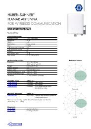
Description of the adjustment mechanism (protective cap removed):<br />
1<br />
1<br />
2<br />
2<br />
➀ Adjustment wheel with<br />
twist-lock function.<br />
➁ Downtilt spindle with integrated<br />
scale.<br />
➀ Thread for fixing the protective<br />
cap or the RCU<br />
(Remote Control Unit).<br />
➁ Gearwheel for RCU power<br />
drive.<br />
To set the downtilt angle<br />
exactly, you must look horizontally<br />
at the scale. The<br />
lower edge of the gearwheel<br />
must be used for alignment.<br />
Manual adjustment procedure:<br />
0° – max.°<br />
max.° – 0°<br />
Remove the protective cap.<br />
Set downtilt angle by rotating<br />
the adjustment wheel.<br />
Screw on the protective cap<br />
again.<br />
For antennas without RET, the interface looks<br />
different. In this case you just have to rotate the<br />
adjustment wheel in order to set the downtilt.<br />
Remote Electrical Tilt (RET) For further technical information please see “RET”, page 182...<br />
11
Kathrein <strong>Antennas</strong><br />
Product Description (Type)<br />
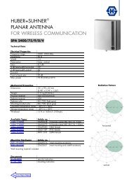
XXPol A-Panel 870–960/1710–1880 C 65°/60° 17/18dBi 2°–8°T/2°T<br />
Polarization(s):<br />
(X) Dual +45°/–45°<br />
(V) Vertical<br />
Antenna Family<br />
Frequency Range(s)<br />
Integrated Combiner<br />
Horizontal<br />
Half-power Beam Width(s)<br />
Gain Value(s)<br />
Variable / Fixed Electrical Tilt(s)<br />
12
Summary – Directional <strong>Antennas</strong><br />
Dual Polarization +45°/–45°<br />
GSM 900 / GSM-R / GSM 850 / CDMA 800<br />
GSM 900<br />
XPol<br />
Dual Polarization +45°/–45°<br />
Type Type No. Height Connector Page<br />
[mm] position<br />
XPol A-Panel 870–960 30° 15.5dBi 741 717 656 bottom 14<br />
XPol A-Panel 806–960 30° 18.5dBi 800 10141 1296 bottom 14<br />
XPol A-Panel 870–960 30° 21dBi 741 785 2580 bottom 15<br />
XPol C-Panel 806–960 33° 21dBi 800 10302 2254 rearside 16<br />
XPol A-Panel 806–960 65° 9dBi 739 619 256 bottom or top 17<br />
XPol A-Panel 806–960 65° 12.5dBi 739 620 656 bottom or top 17<br />
XPol C-Panel 806–960 65° 15.5dBi 800 10202 1294 bottom 18<br />
XPol A-Panel 806–960 65° 15.5dBi 739 622 1296 bottom or top 19<br />
XPol A-Panel 806–960 65° 15dBi 6°T 739 632 1296 bottom 19<br />
XPol C-Panel 806–960 65° 15dBi 6°T 800 10207 1294 bottom 20<br />
XPol C-Panel 806–960 65° 17.5dBi 0°–8°T 800 10305 2254 rearside 21<br />
XPol C-Panel 806–960 65° 16.3dBi 0°–10°T 800 10304 1694 rearside 22<br />
XPol A-Panel 806–960 65° 15dBi 12°T 739 633 1296 bottom 23<br />
XPol A-Panel 806–960 65° 15dBi 0°–14°T 739 684 1296 bottom 24<br />
XPol C-Panel 806–960 65° 15dBi 0°–14°T 800 10303 1294 rearside 25<br />
XPol C-Panel 806–960 65° 17dBi 800 10203 1934 rearside 26<br />
XPol A-Panel 806–960 65° 17dBi 739 623 1936 bottom or top 27<br />
XPol C-Panel 806–960 65° 17dBi 3°T 800 10293 1934 rearside 28<br />
XPol A-Panel 806–960 65° 17dBi 6°T 739 634 1936 bottom 29<br />
XPol C-Panel 806–960 65° 17dBi 6°T 800 10294 1934 rearside 30<br />
XPol A-Panel 824–960 65° 17dBi 9°T 741 622 1936 bottom 31<br />
XPol A-Panel 824–960 65° 16.5dBi 0°–10°T 739 685 1996 bottom 32<br />
XPol A-Panel 870–960 65° 18dBi 739 630 2580 bottom or top 33<br />
XPol A-Panel 806–960 65° 18dBi 739 624 2580 bottom or top 33<br />
XPol C-Panel 806–960 65° 18dBi 800 10204 2254 rearside 34<br />
XPol A-Panel 806–960 65° 18dBi 6°T 739 636 2580 bottom 35<br />
XPol A-Panel 806–960 65° 18dBi 9°T 739 637 2580 bottom 35<br />
XPol A-Panel 806–960 65° 17.5dBi 0°–7°T 739 686 2580 bottom 36<br />
XPol A-Panel 806–960 88° 13.5dBi 739 648 1296 bottom or top 37<br />
XPol A-Panel 806–960 88° 14dBi 6°T 739 658 1296 bottom 38<br />
XPol A-Panel 824–960 88° 13.5dBi 0°–14°T 739 664 1296 bottom 39<br />
XPol A-Panel 870–960 90° 15.5dBi 739 655 1936 bottom or top 40<br />
XPol A-Panel 806–960 88° 15.5dBi 739 649 1936 bottom or top 41<br />
XPol A-Panel 806–960 88° 15.5dBi 6°T 739 660 1936 bottom 41<br />
XPol A-Panel 806–960 88° 15dBi 0°–10°T 739 665 1996 bottom 42<br />
XPol A-Panel 806–960 88° 17dBi 739 650 2580 bottom or top 43<br />
XPol C-Panel 806–960 88° 17dBi 800 10213 2254 rearside 44<br />
XPol A-Panel 806–960 88° 17dBi 6°T 739 662 2580 bottom 45<br />
XPol A-Panel 806–960 88° 16dBi 0°–7°T 739 666 2580 bottom 46<br />
13
dB<br />
dB<br />
dB<br />
dB<br />
GSM 900<br />
XPol<br />
A-Panel<br />
Dual Polarization<br />
Half-power Beam Width<br />
800/900<br />
X<br />
30°<br />
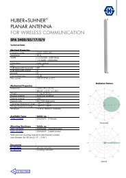
XPol A-Panel 870–960 30° 15.5dBi<br />
Type No.<br />
Frequency range<br />
741 717<br />
870 – 960 <strong>MHz</strong><br />
Polarization +45°, –45°<br />
Gain<br />
2 x 15.5 dBi<br />
Half-power beam width Horizontal: 30°<br />
Copolar +45°/ –45° Vertical: 27°<br />
Front-to-back ratio, copolar<br />
> 30 dB<br />
Isolation<br />
> 30 dB<br />
Impedance<br />
50 Ω<br />
VSWR < 1.5<br />
Intermodulation IM3<br />
< –150 dBc<br />
(2 x 43 dBm carrier)<br />
Max. power per input<br />
500 W (at 50 °C ambient temperature)<br />
Input<br />
2 x 7-16 female<br />
Connector position<br />
Bottom<br />
Weight<br />
13 kg<br />
Wind load (at 150 km/h)<br />
Frontal / Lateral / Rearside:<br />
330 N / 60 N / 470 N<br />
Max. wind velocity<br />
200 km/h<br />
Height/width/depth<br />
656 / 560 / 116 mm<br />
10<br />
3<br />
0<br />
Horizontal Pattern<br />
10<br />
3<br />
0<br />
Vertical Pattern<br />
30°<br />
27°<br />
800/900<br />
–45°<br />
800/900<br />
+45°<br />
XPol A-Panel 806–960 30° 18.5dBi<br />
Type No.<br />
800 10141<br />
Frequency range<br />
806–960<br />
806 – 894 <strong>MHz</strong> 880 – 960 <strong>MHz</strong><br />
Polarization +45°, –45° +45°, –45°<br />
Gain 2 x 18 dBi 2 x 18.5 dBi<br />
Half-power beam width Horizontal: 31° Horizontal: 29°<br />
Copolar +45°/ –45° Vertical: 15° Vertical: 14°<br />
Front-to-back ratio, copolar > 25 dB > 29 dB<br />
Isolation > 30 dB > 30 dB<br />
Impedance 50 Ω 50 Ω<br />
VSWR < 1.5 < 1.5<br />
Intermodulation IM3<br />
< –150 dBc<br />
(2 x 43 dBm carrier)<br />
Max. power per input<br />
500 W (at 50 °C ambient temperature)<br />
Input<br />
2 x 7-16 female<br />
Connector position<br />
Bottom<br />
Weight<br />
22 kg<br />
Wind load (at 150 km/h)<br />
Frontal / Lateral / Rearside:<br />
680 N / 130 N / 970 N<br />
Max. wind velocity<br />
200 km/h<br />
Height/width/depth<br />
1296 / 560 / 116 mm<br />
10<br />
3<br />
0<br />
7-16 7-16<br />
29°<br />
Horizontal Pattern<br />
14°<br />
10<br />
3<br />
0<br />
Vertical Pattern<br />
14 Mounting accessories are not included in the scope of delivery (see page 227)
dB<br />
dB<br />
A-Panel<br />
Dual Polarization<br />
Half-power Beam Width<br />
870–960<br />
X<br />
30°<br />
GSM 900<br />
XPol<br />
XPol A-Panel 870–960 30° 21dBi<br />
Type No.<br />
Frequency range<br />
741 785<br />
870 – 960 <strong>MHz</strong><br />
Polarization +45°, –45°<br />
Gain<br />
2 x 21 dBi<br />
Half-power beam width Horizontal: 30°<br />
Copolar +45°/ –45° Vertical: 7°<br />
Front-to-back ratio, copolar<br />
> 30 dB<br />
Isolation<br />
> 30 dB<br />
Impedance<br />
50 Ω<br />
VSWR < 1.5<br />
Intermodulation IM3<br />
< –150 dBc<br />
(2 x 43 dBm carrier)<br />
Max. power per input<br />
400 W (at 50 °C ambient temperature)<br />
Input<br />
2 x 7-16 female<br />
Connector position<br />
Bottom<br />
Weight<br />
40 kg<br />
Wind load (at 150 km/h)<br />
Frontal / Lateral / Rearside:<br />
1460 N / 280 N / 2090 N<br />
Max. wind velocity<br />
200 km/h<br />
Height/width/depth<br />
2580 / 560 / 116 mm<br />
10<br />
3<br />
0<br />
Horizontal Pattern<br />
10<br />
3<br />
0<br />
Vertical Pattern<br />
30°<br />
7°<br />
870–960<br />
–45°<br />
870–960<br />
+45°<br />
7-16 7-16<br />
Mounting accessories are not included in the scope of delivery (see page 227)<br />
15
dB<br />
dB<br />
dB<br />
dB<br />
dB<br />
dB<br />
GSM 900<br />
XPol<br />
Compact Panel<br />
Dual Polarization<br />
Half-power Beam Width<br />
Fixed Electrical Downtilt<br />
806–960<br />
X<br />
33°<br />
0°<br />
XPol C-Panel 806–960 33° 21dBi 0°T<br />
Type No.<br />
800 10302<br />
Frequency range<br />
806–960<br />
806 – 866 <strong>MHz</strong> 824 – 894 <strong>MHz</strong> 880 – 960 <strong>MHz</strong><br />
Polarization +45°, –45° +45°, –45° +45°, –45°<br />
Gain 2 x 20.2 dBi 2 x 20.4 dBi 2 x 20.8 dBi<br />
Half-power beam width Horizontal: 34° Horizontal: 33° Horizontal: 30°<br />
Copolar +45°/ –45° Vertical: 8.5° Vertical: 8.2° Vertical: 7.5°<br />
Sidelobe suppression for:<br />
first sidelobe above horizon > 15 dB > 15 dB > 15 dB<br />
sector 0°– 30° above horizon > 15 dB > 15 dB > 15 dB<br />
Front-to-back ratio, copolar > 24 dB > 24 dB > 24 dB<br />
Isolation > 30 dB > 30 dB > 30 dB<br />
Crosspolar ratio<br />
Maindirection 0° > 25 dB > 25 dB > 25 dB<br />
Impedance 50 Ω 50 Ω 50 Ω<br />
VSWR < 1.5 < 1.5 < 1.5<br />
Intermodulation IM3<br />
< –150 dBc<br />
(2 x 43 dBm carrier)<br />
Max. power per input<br />
500 W (at 50 °C ambient temperature)<br />
880 – 960 <strong>MHz</strong>: +45°/–45° Polarization<br />
52°<br />
30°<br />
7.5°<br />
10<br />
10<br />
3<br />
3<br />
0<br />
0<br />
Horizontal Pattern Vertical Pattern<br />
824 – 894 <strong>MHz</strong>: +45°/–45° Polarization<br />
806–960<br />
–45°<br />
806–960<br />
+45°<br />
56°<br />
33°<br />
8.2°<br />
7-16 7-16<br />
10<br />
10<br />
3<br />
3<br />
0<br />
0<br />
Horizontal Pattern Vertical Pattern<br />
806 – 866 <strong>MHz</strong>: +45°/–45° Polarization<br />
58° 34°<br />
8.5°<br />
10<br />
10<br />
3<br />
3<br />
0<br />
0<br />
Horizontal Pattern Vertical Pattern<br />
Mechanical specifications<br />
Input<br />
2 x 7-16 female<br />
Connector position Rearside, pointing downwards<br />
Weight<br />
30 kg<br />
Wind load Frontal: 1275 N (at 150 km/h)<br />
Lateral: 260 N (at 150 km/h)<br />
Rearside: 1750 N (at 150 km/h)<br />
Max. wind velocity<br />
200 km/h<br />
Packing size<br />
2416 x 564 x 204 mm<br />
Height/width/depth<br />
2254 / 527 / 99 mm<br />
16 Mounting accessories are not included in the scope of delivery (see page 227)
dB<br />
dB<br />
dB<br />
dB<br />
A-Panel<br />
Dual Polarization<br />
Half-power Beam Width<br />
806–960<br />
X<br />
65°<br />
GSM 900<br />
XPol<br />
XPol A-Panel 806–960 65° 9dBi<br />
Type No.<br />
739 619<br />
Frequency range<br />
806–960<br />
806 – 880 <strong>MHz</strong> 880 – 960 <strong>MHz</strong><br />
Polarization +45°, –45° +45°, –45°<br />
Gain 2 x 8.5 dBi 2 x 9 dBi<br />
Half-power beam width Horizontal: 70° Horizontal: 65°<br />
Copolar +45°/ –45° Vertical: 70° Vertical: 68°<br />
Front-to-back ratio, copolar > 27 dB > 27 dB<br />
Cross polar ratio<br />
Maindirection 0° Typically: 25 dB Typically: 25 dB<br />
Sector ±60° > 10 dB > 10 dB<br />
Isolation<br />
> 30 dB<br />
Impedance<br />
50 Ω<br />
VSWR < 1.5<br />
Intermodulation IM3<br />
< –150 dBc<br />
(2 x 43 dBm carrier)<br />
Max. power per input<br />
350 W (at 50 °C ambient temperature)<br />
Input<br />
2 x 7-16 female<br />
Connector position<br />
Bottom or top<br />
Weight<br />
3 kg<br />
Wind load (at 150 km/h)<br />
Frontal / Lateral / Rearside:<br />
40 N / 25 N / 90 N<br />
Max. wind velocity<br />
200 km/h<br />
Height/width/depth<br />
256 / 262 / 116 mm<br />
10<br />
3<br />
0<br />
125°<br />
Horizontal Pattern<br />
10<br />
3<br />
0<br />
Vertical Pattern<br />
806–960<br />
–45°<br />
65°<br />
68°<br />
806–960<br />
+45°<br />
XPol A-Panel 806–960 65° 12.5dBi<br />
Type No.<br />
739 620<br />
Frequency range<br />
806–960<br />
806 – 880 <strong>MHz</strong> 880 – 960 <strong>MHz</strong><br />
Polarization +45°, –45° +45°, –45°<br />
Gain 2 x 12 dBi 2 x 12.5 dBi<br />
Half-power beam width Horizontal: 68° Horizontal: 65°<br />
Copolar +45°/ –45° Vertical: 29° Vertical: 27°<br />
Front-to-back ratio, copolar<br />
> 30 dB<br />
Isolation<br />
> 30 dB<br />
Impedance<br />
50 Ω<br />
VSWR < 1.5<br />
Intermodulation IM3<br />
< –150 dBc<br />
(2 x 43 dBm carrier)<br />
Max. power per input<br />
500 W (at 50 °C ambient temperature)<br />
Input<br />
2 x 7-16 female<br />
Connector position<br />
Bottom or top<br />
Weight<br />
6 kg<br />
Wind load (at 150 km/h)<br />
Frontal / Lateral / Rearside:<br />
110 N / 60 N / 240 N<br />
Max. wind velocity<br />
200 km/h<br />
Height/width/depth<br />
656 / 262 / 116 mm<br />
7-16 7-16<br />
65°<br />
120°<br />
10<br />
3<br />
0<br />
Horizontal Pattern<br />
27°<br />
10<br />
3<br />
0<br />
Vertical Pattern<br />
Mounting accessories are not included in the scope of delivery (see page 228 – 233)<br />
17
dB<br />
dB<br />
dB<br />
dB<br />
dB<br />
dB<br />
GSM 900<br />
XPol<br />
Compact Panel<br />
Dual Polarization<br />
Half-power Beam Width<br />
Fixed Electrical Downtilt<br />
806–960<br />
X<br />
65°<br />
0°<br />
XPol C-Panel 806–960 65° 15.5dBi 0°T<br />
Type No.<br />
800 10202<br />
Frequency range<br />
806–960<br />
806 – 866 <strong>MHz</strong> 824 – 894 <strong>MHz</strong> 880 – 960 <strong>MHz</strong><br />
Polarization +45°, –45° +45°, –45° +45°, –45°<br />
Gain 2 x 14.7 dBi 2 x 15 dBi 2 x 15.3 dBi<br />
Half-power beam width Horizontal: 67° Horizontal: 66° Horizontal: 64°<br />
Copolar +45°/ –45° Vertical: 15.5° Vertical: 14.8° Vertical: 14°<br />
Sidelobe suppression for:<br />
first sidelobe above horizon > 15 dB > 15 dB > 14 dB<br />
sector 0°– 30° above horizon > 15 dB > 15 dB > 14 dB<br />
Front-to-back ratio, copolar > 30 dB > 30 dB > 30 dB<br />
Isolation > 30 dB > 30 dB > 30 dB<br />
Crosspolar ratio<br />
Maindirection 0° > 20 dB > 20 dB > 20 dB<br />
Sector ±30° > 19 dB > 19 dB > 20 dB<br />
Sector ±60° > 11 dB > 11 dB > 11 dB<br />
Impedance 50 Ω 50 Ω 50 Ω<br />
VSWR < 1.5 < 1.4 < 1.3<br />
Intermodulation IM3<br />
< –150 dBc<br />
(2 x 43 dBm carrier)<br />
Max. power per input<br />
500 W (at 50 °C ambient temperature)<br />
880 – 960 <strong>MHz</strong>: +45°/–45° Polarization<br />
120°<br />
64°<br />
14°<br />
10<br />
10<br />
3<br />
3<br />
0<br />
0<br />
Horizontal Pattern Vertical Pattern<br />
824 – 894 <strong>MHz</strong>: +45°/–45° Polarization<br />
806–960<br />
–45°<br />
806–960<br />
+45°<br />
124°<br />
66°<br />
14.8°<br />
7-16 7-16<br />
10<br />
10<br />
3<br />
0<br />
Horizontal Pattern Vertical Pattern<br />
806 – 866 <strong>MHz</strong>: +45°/–45° Polarization<br />
10<br />
3<br />
0<br />
67°<br />
127°<br />
15.5°<br />
Horizontal Pattern Vertical Pattern<br />
3<br />
0<br />
10<br />
3<br />
0<br />
Mechanical specifications<br />
Input<br />
2 x 7-16 female<br />
Connector position<br />
Bottom<br />
Weight<br />
7.5 kg<br />
Wind load Frontal: 220 N (at 150 km/h)<br />
Lateral: 140 N (at 150 km/h)<br />
Rearside: 490 N (at 150 km/h)<br />
Max. wind velocity<br />
200 km/h<br />
Packing size<br />
1436 x 292 x 138 mm<br />
Height/width/depth<br />
1294 / 259 / 99 mm<br />
18 Mounting accessories are not included in the scope of delivery (see page 228 – 233)
dB<br />
dB<br />
dB<br />
dB<br />
A-Panel<br />
Dual Polarization<br />
Half-power Beam Width<br />
806–960<br />
X<br />
65°<br />
GSM 900<br />
XPol<br />
XPol A-Panel 806–960 65° 15.5dBi<br />
Type No.<br />
739 622<br />
Frequency range<br />
806–960<br />
806 – 880 <strong>MHz</strong> 880 – 960 <strong>MHz</strong><br />
Polarization +45°, –45° +45°, –45°<br />
Gain 2 x 15 dBi 2 x 15.5 dBi<br />
Half-power beam width Horizontal: 68° Horizontal: 65°<br />
Copolar +45°/ –45° Vertical: 16° Vertical: 15°<br />
Front-to-back ratio, copolar<br />
> 30 dB<br />
Isolation<br />
> 30 dB<br />
Impedance<br />
50 Ω<br />
VSWR < 1.4<br />
Intermodulation IM3<br />
< –150 dBc<br />
(2 x 43 dBm carrier)<br />
Max. power per input<br />
600 W (at 50 °C ambient temperature)<br />
Input<br />
2 x 7-16 female<br />
Connector position<br />
Bottom or top<br />
Weight<br />
11 kg<br />
Wind load (at 150 km/h)<br />
Frontal / Lateral / Rearside:<br />
230 N / 130 N / 500 N<br />
Max. wind velocity<br />
200 km/h<br />
Height/width/depth<br />
1296 / 262 / 116 mm<br />
65°<br />
120°<br />
10<br />
3<br />
0<br />
Horizontal Pattern<br />
15°<br />
10<br />
3<br />
0<br />
Vertical Pattern<br />
806–960<br />
–45°<br />
806–960<br />
+45°<br />
XPol A-Panel 806–960 65° 15dBi 6°T<br />
Type No.<br />
739 632<br />
Frequency range<br />
806–960<br />
806 – 880 <strong>MHz</strong> 880 – 960 <strong>MHz</strong><br />
Polarization +45°, –45° +45°, –45°<br />
Gain 2 x 14.5 dBi 2 x 15 dBi<br />
Half-power beam width Horizontal: 68° Horizontal: 65°<br />
Copolar +45°/ –45° Vertical: 16° Vertical: 15°<br />
Electrical tilt 6°, fixed 6°, fixed<br />
Sidelobe suppression for ≥ 14 dB ≥ 16 dB<br />
first sidelobe above horizon<br />
Front-to-back ratio, copolar > 28 dB > 30 dB<br />
Isolation > 30 dB > 32 dB<br />
Impedance 50 Ω 50 Ω<br />
VSWR < 1.5 < 1.3<br />
Intermodulation IM3<br />
< –150 dBc<br />
(2 x 43 dBm carrier)<br />
Max. power per input<br />
600 W (at 50 °C ambient temperature)<br />
Input<br />
2 x 7-16 female<br />
Connector position<br />
Bottom<br />
Weight<br />
11 kg<br />
Wind load (at 150 km/h)<br />
Frontal / Lateral / Rearside:<br />
230 N / 130 N / 500 N<br />
Max. wind velocity<br />
200 km/h<br />
Height/width/depth<br />
1296 / 262 / 116 mm<br />
Mounting accessories are not included in the scope of delivery (see page 228 – 233)<br />
10<br />
3<br />
0<br />
120°<br />
Horizontal Pattern<br />
10<br />
3<br />
0<br />
7-16 7-16<br />
65°<br />
Vertical Pattern<br />
6° electrical downtilt<br />
15°<br />
19
dB<br />
dB<br />
dB<br />
dB<br />
dB<br />
dB<br />
GSM 900<br />
XPol<br />
Compact Panel<br />
Dual Polarization<br />
Half-power Beam Width<br />
Fixed Electrical Downtilt<br />
XPol C-Panel 806–960 65° 15dBi 6°T<br />
Type No.<br />
806–960<br />
X<br />
65°<br />
6°<br />
800 10207<br />
Frequency range<br />
806–960<br />
806 – 866 <strong>MHz</strong> 824 – 894 <strong>MHz</strong> 880 – 960 <strong>MHz</strong><br />
Polarization +45°, –45° +45°, –45° +45°, –45°<br />
Gain 2 x 14.5 dBi 2 x 14.7 dBi 2 x 15 dBi<br />
Half-power beam width Horizontal: 66° Horizontal: 65° Horizontal: 63°<br />
Copolar +45°/ –45° Vertical: 16° Vertical: 15.7° Vertical: 14.6°<br />
Electrical tilt 6°, fixed 6°, fixed 6°, fixed<br />
Sidelobe suppression for:<br />
first sidelobe above horizon > 13 dB > 14 dB > 16 dB<br />
sector 0°–30° above horizon > 13 dB > 14 dB > 14 dB<br />
Front-to-back ratio, copolar > 30 dB > 30 dB > 30 dB<br />
Isolation > 30 dB > 30 dB > 30 dB<br />
Cross polar ratio<br />
Maindirection 0° Tpyically: > 20 dB Typically: > 20 dB Typically: > 20 dB<br />
Sector ±60° Typically: > 10 dB Typically: > 10 dB Typically: > 10 dB<br />
Impedance 50 Ω 50 Ω 50 Ω<br />
VSWR < 1.3 < 1.3 < 1.3<br />
Intermodulation IM3<br />
< –150 dBc<br />
(2 x 43 dBm carrier)<br />
Max. power per input<br />
500 W (at 50 °C ambient temperature)<br />
880 – 960 <strong>MHz</strong>: +45°/–45° Polarization<br />
118°<br />
63°<br />
14.6°<br />
10<br />
10<br />
3<br />
3<br />
0<br />
Horizontal Pattern<br />
0<br />
Vertical Pattern<br />
6° electrical downtilt<br />
824 – 894 <strong>MHz</strong>: +45°/–45° Polarization<br />
123°<br />
65°<br />
806–960<br />
–45°<br />
806–960<br />
+45°<br />
15.7°<br />
10<br />
3<br />
10<br />
3<br />
7-16 7-16<br />
0<br />
Horizontal Pattern<br />
Horizontal Pattern<br />
0<br />
Vertical Pattern<br />
6° electrical downtilt<br />
806 – 866 <strong>MHz</strong>: +45°/–45° Polarization<br />
10<br />
3<br />
0<br />
125°<br />
66°<br />
10<br />
3<br />
0<br />
16°<br />
Vertical Pattern<br />
6° electrical downtilt<br />
Mechanical specifications<br />
Input<br />
2 x 7-16 female<br />
Connector position<br />
Bottom<br />
Weight<br />
7.5 kg<br />
Wind load Frontal: 220 N (at 150 km/h)<br />
Lateral: 140 N (at 150 km/h)<br />
Rearside: 490 N (at 150 km/h)<br />
Max. wind velocity<br />
200 km/h<br />
Packing size<br />
1436 x 292 x 138 mm<br />
Height/width/depth<br />
1294 / 259 / 99 mm<br />
20 Mounting accessories are not included in the scope of delivery (see page 228 – 233)
dB<br />
dB<br />
dB<br />
dB<br />
dB<br />
dB<br />
Compact Panel<br />
Dual Polarization<br />
Half-power Beam Width<br />
Adjust. Electrical Downtilt<br />
0°–8°<br />
set by hand or by optional RCU (Remote Control Unit)<br />
XPol C-Panel 806–960 65° 17.5dBi 0°–8°T<br />
Type No.<br />
806–960<br />
X<br />
65°<br />
800 10305<br />
Frequency range<br />
806–960<br />
806 – 866 <strong>MHz</strong> 824 – 894 <strong>MHz</strong> 880 – 960 <strong>MHz</strong><br />
Polarization +45°, –45° +45°, –45° +45°, –45°<br />
Average gain (dBi) 16.8 ... 17 ... 16.7 16.9 ... 17.1 ... 16.9 17.2 ... 17.4 ... 17.1<br />
Tilt 0° ... 4° ... 8° 0° ... 4° ... 8° 0° ... 4° ... 8°<br />
Half-power beam width Horizontal: 69° Horizontal: 67° Horizontal: 65°<br />
Copolar +45°/ –45° Vertical: 9.1° Vertical: 8.8° Vertical: 8.5°<br />
Electrical tilt 0°–8° 0°–8° 0°–8°<br />
continuously adjustable<br />
Vertical Pattern – sidelobe 0° ... 2° ... 4° ... 8° T 0° ... 2° ... 4° ... 8° T 0° ... 2° ... 4° ... 8° T<br />
suppression for first sidelobe 17 ... 16 ... 15 ... 14 dB 17 ... 16 ... 15 ... 14 dB 20 ... 18 ... 17 ... 15 dB<br />
above main beam<br />
Front-to-back ratio, copolar > 25 dB > 25 dB > 25 dB<br />
Isolation, between ports > 30 dB > 30 dB > 30 dB<br />
Cross polar ratio<br />
Maindirection 0° Typically: 25 dB Typically: 25 dB Typically: 25 dB<br />
Sector ±60° Typically: > 10 dB Typically: > 10 dB Typically: > 10 dB<br />
Impedance 50 Ω 50 Ω 50 Ω<br />
VSWR < 1.5 < 1.5 < 1.5<br />
Intermodulation IM3<br />
< –150 dBc<br />
(2 x 43 dBm carrier)<br />
Max. power per input<br />
500 W (at 50 °C ambient temperature)<br />
GSM 900<br />
XPol<br />
880 – 960 <strong>MHz</strong>: +45°/–45° Polarization<br />
122°<br />
65°<br />
8.5°<br />
10<br />
10<br />
3<br />
3<br />
0<br />
Horizontal Pattern Vertical Pattern<br />
0°–8° electrical downtilt<br />
824 – 894 <strong>MHz</strong>: +45°/–45° Polarization<br />
0<br />
806–960<br />
–45°<br />
806–960<br />
+45°<br />
130°<br />
67°<br />
8.8°<br />
7-16 7-16<br />
10<br />
10<br />
Mechanical specifications<br />
3<br />
0<br />
Horizontal Pattern Vertical Pattern<br />
0°–8° electrical downtilt<br />
806 – 866 <strong>MHz</strong>: +45°/–45° Polarization<br />
10<br />
3<br />
0<br />
135°<br />
69°<br />
Horizontal Pattern<br />
3<br />
0<br />
10<br />
3<br />
0<br />
9.1°<br />
Vertical Pattern<br />
0°–8° electrical downtilt<br />
Input<br />
2 x 7-16 female<br />
Connector position Rearside, pointing downwards<br />
Adjustment<br />
1x, Position bottom<br />
mechanism<br />
continuously adjustable<br />
Weight<br />
16 kg<br />
Wind load Frontal: 400 N (at 150 km/h)<br />
Lateral: 260 N (at 150 km/h)<br />
Rearside: 890 N (at 150 km/h)<br />
Max. wind velocity<br />
200 km/h<br />
Packing size<br />
2536 x 292 x 192 mm<br />
Height/width/depth<br />
2254 / 259 / 99 mm<br />
Mounting accessories are not included in the scope of delivery (see page 228 – 233)<br />
For more information about downtilt adjustment and preparation for Remote Control Unit (RCU) refer to pages 182 – 191<br />
21
dB<br />
dB<br />
dB<br />
dB<br />
dB<br />
dB<br />
GSM 900<br />
XPol<br />
Compact Panel<br />
Dual Polarization<br />
Half-power Beam Width<br />
Adjust. Electr. Downtilt<br />
806–960<br />
0°– 10°<br />
set by hand or by optional RCU (Remote Control Unit)<br />
XPol C-Panel 806–960 65° 16.3dBi 0°–10°T<br />
Type No.<br />
X<br />
65°<br />
800 10304<br />
Frequency range<br />
806–960<br />
806 – 866 <strong>MHz</strong> 824 – 894 <strong>MHz</strong> 880 – 960 <strong>MHz</strong><br />
Polarization +45°, –45° +45°, –45 +45°, –45°<br />
Average gain (dBi) 15.6 ... 15.8 ... 15.5 15.7 ... 16.1 ... 15.7 16 ... 16.3 ... 15.9<br />
Tilt 0° ... 5° ... 10° 0° ... 5° ... 10° 0° ... 5° ... 10°<br />
Half-power beam width Horizontal: 69° Horizontal: 67° Horizontal: 65°<br />
Copolar +45°/ –45° Vertical: 12.5° Vertical: 12° Vertical: 11.5°<br />
Electrical tilt 0°– 10° 0°– 10° 0°– 10°<br />
continuously adjustable<br />
Sidelobe suppression for 0° ... 3° ... 6° ... 10°T 0° ... 3° ... 6° ... 10°T 0° ... 3° ... 6° ... 10°T<br />
first sidelobe above horizon 15 ... 14 ... 12 ... 12 dB 15 ... 15 ... 15 ... 14 dB 15 ... 15 ... 15 ... 14 dB<br />
Front-to-back ratio, copolar > 25 dB > 25 dB > 25 dB<br />
Cross polar ratio<br />
Maindirection 0° Typically: 25 dB Typically: 25 dB Typically: 25 dB<br />
Sector ±60° > 10 dB > 10 dB > 10 dB<br />
Isolation, between ports > 30 dB > 30 dB > 30 dB<br />
Impedance 50 Ω 50 Ω 50 Ω<br />
VSWR < 1.5 < 1.5 < 1.5<br />
Intermodulation IM3<br />
< –150 dBc<br />
(2 x 43 dBm carrier)<br />
Max. power per input<br />
400 W (at 50 °C ambient temperature)<br />
880 – 960 <strong>MHz</strong>: +45°/–45° Polarization<br />
122°<br />
65°<br />
11.5°<br />
10<br />
10<br />
3<br />
3<br />
0<br />
Horizontal Pattern<br />
0<br />
Vertical Pattern<br />
0°–10° electrical downtilt<br />
824 – 894 <strong>MHz</strong>: +45°/–45° Polarization<br />
806–960<br />
–45°<br />
806–960<br />
+45°<br />
130°<br />
67°<br />
12°<br />
7-16 7-16<br />
10<br />
10<br />
Mechanical specifications<br />
3<br />
0<br />
Horizontal Pattern<br />
10<br />
3<br />
0<br />
135°<br />
69°<br />
Horizontal Pattern<br />
3<br />
0<br />
Vertical Pattern<br />
0°–10° electrical downtilt<br />
806 – 866 <strong>MHz</strong>: +45°/–45° Polarization<br />
10<br />
3<br />
0<br />
12.5°<br />
Vertical Pattern<br />
0°–10° electrical downtilt<br />
Input<br />
2 x 7-16 female<br />
Connector position Rearside, pointing downwards<br />
Adjustment<br />
1x, Position bottom<br />
mechanism<br />
continuously adjustable<br />
Weight<br />
13 kg<br />
Wind load Frontal: 300 N (at 150 km/h)<br />
Lateral: 195 N (at 150 km/h)<br />
Rearside: 660 N (at 150 km/h)<br />
Max. wind velocity<br />
200 km/h<br />
Packing size<br />
1976 x 292 x 192 mm<br />
Height/width/depth<br />
1694 / 259 / 99 mm<br />
22 Mounting accessories are not included in the scope of delivery (see page 228 – 233)<br />
For more information about downtilt adjustment and preparation for Remote Control Unit (RCU) refer to pages 182 – 191
dB<br />
dB<br />
A-Panel<br />
Dual Polarization<br />
Half-power Beam Width<br />
806–960<br />
X<br />
65°<br />
GSM 900<br />
XPol<br />
XPol A-Panel 806–960 65° 15dBi 12°T<br />
Type No.<br />
739 633<br />
Frequency range<br />
806–960<br />
806 – 880 <strong>MHz</strong> 880 – 960 <strong>MHz</strong><br />
Polarization +45°, –45° +45°, –45°<br />
Gain 2 x 14.5 dBi 2 x 15 dBi<br />
Half-power beam width Horizontal: 68° Horizontal: 65°<br />
Copolar +45°/ –45° Vertical: 17° Vertical: 16°<br />
Electrical tilt 12°, fixed 12°, fixed<br />
Sidelobe suppression for ≥ 14 dB ≥ 16 dB<br />
first sidelobe above horizon<br />
Front-to-back ratio, copolar > 28 dB > 30 dB<br />
Isolation > 30 dB > 30 dB<br />
Impedance 50 Ω 50 Ω<br />
VSWR < 1.5 < 1.3<br />
Intermodulation IM3<br />
< –150 dBc<br />
(2 x 43 dBm carrier)<br />
Max. power per input<br />
600 W (at 50 °C ambient temperature)<br />
Input<br />
2 x 7-16 female<br />
Connector position<br />
Bottom<br />
Weight<br />
8 kg<br />
Wind load (at 150 km/h)<br />
Frontal / Lateral / Rearside:<br />
230 N / 130 N / 500 N<br />
Max. wind velocity<br />
200 km/h<br />
Height/width/depth<br />
1296 / 262 / 116 mm<br />
10<br />
3<br />
0<br />
120°<br />
Horizontal Pattern<br />
10<br />
3<br />
0<br />
65°<br />
Vertical Pattern<br />
12° electrical downtilt<br />
806–960<br />
–45°<br />
16°<br />
806–960<br />
+45°<br />
7-16 7-16<br />
Mounting accessories are not included in the scope of delivery (see page 228 – 233)<br />
23
dB<br />
dB<br />
dB<br />
dB<br />
dB<br />
dB<br />
GSM 900<br />
XPol<br />
A-Panel<br />
Dual Polarization<br />
Half-power Beam Width<br />
Adjust. Electr. Downtilt<br />
806–960<br />
0°–14°<br />
set by hand or by optional RCU (Remote Control Unit)<br />
X<br />
65°<br />
XPol A-Panel 806–960 65° 15dBi 0°–14°T<br />
Type No.<br />
880 – 960 <strong>MHz</strong>: +45°/–45° Polarization<br />
739 684<br />
Frequency range<br />
806–960<br />
806 – 866 <strong>MHz</strong> 824 – 894 <strong>MHz</strong> 880 – 960 <strong>MHz</strong><br />
Polarization +45°, –45° +45°, –45° +45°, –45°<br />
Gain 14.5 dBi 14.7 dBi 15 dBi<br />
Half-power beam width Horizontal: 70° Horizontal: 68° Horizontal: 65°<br />
Copolar +45°/ –45° Vertical: 16° Vertical: 15.5° Vertical: 15°<br />
Electrical tilt 0°–14° 0°–14° 0°–14°<br />
continuously adjustable<br />
Vertical Pattern – sidelobe<br />
suppression for sector 0°–30°<br />
above main beam 14 dB 15 dB 15 dB<br />
Front-to-back ratio, copolar > 25 dB > 25 dB > 25 dB<br />
Cross polar ratio<br />
Maindirection 0° Typically: 25 dB Typically: 25 dB Typically: 25 dB<br />
Sector ±60° > 10 dB > 10 dB > 10 dB<br />
Isolation, between ports > 30 dB > 30 dB > 30 dB<br />
Impedance 50 Ω 50 Ω 50 Ω<br />
VSWR < 1.5 < 1.5 < 1.5<br />
Intermodulation IM3<br />
< –150 dBc<br />
(2 x 43 dBm carrier)<br />
Max. power per input<br />
400 W (at 50 °C ambient temperature)<br />
125°<br />
65°<br />
15°<br />
10<br />
10<br />
3<br />
3<br />
0<br />
Horizontal Pattern<br />
Vertical Pattern<br />
0°–14° electrical downtilt<br />
824 – 894 <strong>MHz</strong>: +45°/–45° Polarization<br />
0<br />
806–960<br />
–45°<br />
806–960<br />
+45°<br />
130°<br />
68°<br />
15.5°<br />
7-16 7-16<br />
10<br />
10<br />
Mechanical specifications<br />
3<br />
0<br />
Horizontal Pattern<br />
10<br />
3<br />
135°<br />
70°<br />
Vertical Pattern<br />
0°–14° electrical downtilt<br />
806 – 866 <strong>MHz</strong>: +45°/–45° Polarization<br />
3<br />
0<br />
10<br />
3<br />
16°<br />
Input<br />
2 x 7-16 female<br />
Connector position<br />
Bottom<br />
Adjustment<br />
1x, Position bottom<br />
mechanism<br />
continuously adjustable<br />
Weight<br />
14 kg<br />
Wind load Frontal: 230 N (at 150 km/h)<br />
Lateral: 130 N (at 150 km/h)<br />
Rearside: 500 N (at 150 km/h)<br />
Max. wind velocity<br />
200 km/h<br />
Packing size<br />
1562 x 287 x 165 mm<br />
Height/width/depth 1296 / 262 / 116 mm<br />
0<br />
Horizontal Pattern<br />
0<br />
Vertical Pattern<br />
0°–14° electrical downtilt<br />
24 Mounting accessories are not included in the scope of delivery (see page 228 – 233)<br />
For more information about downtilt adjustment and preparation for Remote Control Unit (RCU) refer to pages 182 – 191
dB<br />
dB<br />
dB<br />
dB<br />
dB<br />
dB<br />
Compact Panel<br />
Dual Polarization<br />
Half-power Beam Width<br />
Adjust. Electr. Downtilt<br />
806–960<br />
0°–14°<br />
set by hand or by optional RCU (Remote Control Unit)<br />
X<br />
65°<br />
GSM 900<br />
XPol<br />
XPol C-Panel 806–960 65° 15dBi 0°–14°T<br />
Type No.<br />
880 – 960 <strong>MHz</strong>: +45°/–45° Polarization<br />
800 10303<br />
Frequency range<br />
806–960<br />
806 – 866 <strong>MHz</strong> 824 – 894 <strong>MHz</strong> 880 – 960 <strong>MHz</strong><br />
Polarization +45°, –45° +45°, –45° +45°, –45°<br />
Average gain (dBi) 14.5 ... 14.5 ... 14.2 14.7 ... 14.7 ... 14.5 15 ... 15.1 ... 14.8<br />
Tilt 0° ... 7° ... 14° 0° ... 7° ... 14° 0° ... 7° ... 14°<br />
Half-power beam width Horizontal: 69° Horizontal: 67° Horizontal: 65°<br />
Copolar +45°/ –45° Vertical: 16° Vertical: 15.5° Vertical: 15°<br />
Electrical tilt 0°–14° 0°–14° 0°–14°<br />
continuously adjustable<br />
Sidelobe suppression for 0° ... 7° ... 14° 0° ... 7° ... 14° 0° ... 7° ... 14°<br />
first sidelobe above horizon 14 ... 14 ... 13 dB 15 ... 15 ... 14 dB 15 ... 15 ... 15 dB<br />
Front-to-back ratio, copolar > 25 dB > 25 dB > 25 dB<br />
Cross polar ratio<br />
Maindirection 0° Typically: 25 dB Typically: 25 dB Typically: 25 dB<br />
Sector ±60° > 10 dB > 10 dB > 10 dB<br />
Isolation, between ports > 30 dB > 30 dB > 30 dB<br />
Impedance 50 Ω 50 Ω 50 Ω<br />
VSWR < 1.5 < 1.5 < 1.5<br />
Intermodulation IM3<br />
< –150 dBc<br />
(2 x 43 dBm carrier)<br />
Max. power per input<br />
400 W (at 50 °C ambient temperature)<br />
122°<br />
65°<br />
15°<br />
10<br />
10<br />
3<br />
3<br />
0<br />
Horizontal Pattern<br />
Vertical Pattern<br />
0°–14° electrical downtilt<br />
824 – 894 <strong>MHz</strong>: +45°/–45° Polarization<br />
0<br />
806–960<br />
–45°<br />
806–960<br />
+45°<br />
130°<br />
67°<br />
7-16 7-16<br />
15.5°<br />
10<br />
3<br />
0<br />
Horizontal Pattern<br />
10<br />
3<br />
0<br />
135°<br />
69°<br />
Horizontal Pattern<br />
Vertical Pattern<br />
0°–14° electrical downtilt<br />
806 – 866 <strong>MHz</strong>: +45°/–45° Polarization<br />
10<br />
3<br />
0<br />
10<br />
3<br />
0<br />
16°<br />
Vertical Pattern<br />
0°–14° electrical downtilt<br />
Mechanical specifications<br />
Input<br />
2 x 7-16 female<br />
Connector position<br />
Bottom<br />
Adjustment<br />
1x, Position bottom<br />
mechanism<br />
continuously adjustable<br />
Weight<br />
10 kg<br />
Wind load Frontal: 220 N (at 150 km/h)<br />
Lateral: 140 N (at 150 km/h)<br />
Rearside: 490 N (at 150 km/h)<br />
Max. wind velocity<br />
200 km/h<br />
Packing size<br />
1586 x 292 x 138 mm<br />
Height/width/depth<br />
1294 / 259 / 99 mm<br />
Mounting accessories are not included in the scope of delivery (see page 228 – 233)<br />
For more information about downtilt adjustment and preparation for Remote Control Unit (RCU) refer to pages 182 – 191<br />
25
dB<br />
dB<br />
dB<br />
dB<br />
dB<br />
dB<br />
GSM 900<br />
XPol<br />
Compact Panel<br />
Dual Polarization<br />
Half-power Beam Width<br />
Fixed Electrical Downtilt<br />
806–960<br />
X<br />
65°<br />
0°<br />
XPol C-Panel 806–960 65° 17dBi 0°T<br />
Type No.<br />
800 10203<br />
Frequency range<br />
806–960<br />
806 – 866 <strong>MHz</strong> 824 – 894 <strong>MHz</strong> 880 – 960 <strong>MHz</strong><br />
Polarization +45°, –45° +45°, –45° +45°, –45°<br />
Gain 2 x 16.5 dBi 2 x 16.7 dBi 2 x 17 dBi<br />
Half-power beam width Horizontal: 68° Horizontal: 66° Horizontal: 65°<br />
Copolar +45°/ –45° Vertical: 10.2° Vertical: 10° Vertical: 9.3°<br />
Sidelobe suppression for:<br />
first sidelobe above horizon > 17 dB > 17 dB > 17 dB<br />
sector 0°–30° above horizon > 15 dB > 15 dB > 15 dB<br />
Front-to-back ratio, copolar > 30 dB > 30 dB > 30 dB<br />
Isolation > 30 dB > 30 dB > 30 dB<br />
Cross polar ratio<br />
Maindirection 0° > 20 dB > 20 dB > 20 dB<br />
Sector ±30° > 18 dB > 18 dB > 18 dB<br />
Sector ±60° > 12 dB > 12 dB > 12 dB<br />
Impedance 50 Ω 50 Ω 50 Ω<br />
VSWR < 1.5 < 1.4 < 1.3<br />
Intermodulation IM3<br />
< –150 dBc<br />
(2 x 43 dBm carrier)<br />
Max. power per input<br />
500 W (at 50 °C ambient temperature)<br />
880 – 960 <strong>MHz</strong>: +45°/–45° Polarization<br />
120°<br />
65°<br />
9.3°<br />
10<br />
10<br />
3<br />
3<br />
0<br />
Horizontal Pattern<br />
0<br />
Vertical Pattern<br />
824 – 894 <strong>MHz</strong>: +45°/–45° Polarization<br />
127°<br />
66°<br />
806–960<br />
–45°<br />
806–960<br />
+45°<br />
10°<br />
7-16 7-16<br />
10<br />
3<br />
10<br />
3<br />
Mechanical specifications<br />
0<br />
0<br />
Horizontal Pattern Vertical Pattern<br />
806 – 866 <strong>MHz</strong>: +45°/–45° Polarization<br />
10<br />
3<br />
0<br />
68°<br />
130°<br />
10.2°<br />
Horizontal Pattern Vertical Pattern<br />
10<br />
3<br />
0<br />
Input<br />
2 x 7-16 female<br />
Connector position<br />
Rearside<br />
Weight<br />
11 kg<br />
Wind load Frontal: 340 N (at 150 km/h)<br />
Lateral: 220 N (at 150 km/h)<br />
Rearside: 750 N (at 150 km/h)<br />
Max. wind velocity<br />
200 km/h<br />
Packing size<br />
2066 x 292 x 192 mm<br />
Height/width/depth<br />
1934 / 259 / 99 mm<br />
26 Mounting accessories are not included in the scope of delivery (see page 228 – 233)
dB<br />
dB<br />
A-Panel<br />
Dual Polarization<br />
Half-power Beam Width<br />
806–960<br />
X<br />
65°<br />
GSM 900<br />
XPol<br />
XPol A-Panel 806–960 65° 17dBi<br />
Type No.<br />
739 623<br />
Frequency range<br />
806–960<br />
806 – 894 <strong>MHz</strong> 880 – 960 <strong>MHz</strong><br />
Polarization +45°, –45° +45°, –45°<br />
Gain 2 x 16.5 dBi 2 x 17 dBi<br />
Half-power beam width Horizontal: 68° Horizontal: 65°<br />
Copolar +45°/ –45° Vertical: 10° Vertical: 9.5°<br />
Sidelobe suppression for<br />
≥ 15 dB<br />
first sidelobe above horizon<br />
Front-to-back ratio, copolar<br />
Isolation<br />
Impedance<br />
> 30 dB<br />
> 30 dB<br />
50 Ω<br />
VSWR < 1.5<br />
Intermodulation IM3<br />
< –150 dBc<br />
(2 x 43 dBm carrier)<br />
Max. power per input<br />
600 W (at 50 °C ambient temperature)<br />
Input<br />
2 x 7-16 female<br />
Connector position<br />
Bottom or top<br />
Weight<br />
12 kg<br />
Wind load (at 150 km/h)<br />
Frontal / Lateral / Rearside:<br />
330 N / 200 N / 770 N<br />
Max. wind velocity<br />
200 km/h<br />
Height/width/depth<br />
1936 / 262 / 116 mm<br />
10<br />
3<br />
0<br />
120°<br />
Horizontal Pattern<br />
10<br />
3<br />
0<br />
65°<br />
9.5°<br />
Vertical Pattern<br />
first null-fill below horizon<br />
better or equal –25 dB<br />
below maximum gain<br />
806–960<br />
–45°<br />
806–960<br />
+45°<br />
7-16 7-16<br />
Mounting accessories are not included in the scope of delivery (see page 228 – 233)<br />
27
dB<br />
dB<br />
dB<br />
dB<br />
dB<br />
dB<br />
GSM 900<br />
XPol<br />
Compact Panel<br />
Dual Polarization<br />
Half-power Beam Width<br />
Fixed Electrical Downtilt<br />
XPol C-Panel 806–960 65° 17dBi 3°T<br />
Type No.<br />
806–960<br />
X<br />
65°<br />
3°<br />
800 10293<br />
Frequency range<br />
806–960<br />
806 – 866 <strong>MHz</strong> 824 – 894 <strong>MHz</strong> 880 – 960 <strong>MHz</strong><br />
Polarization +45°, –45° +45°, –45° +45°, –45°<br />
Gain 2 x 16.5 dBi 2 x 16.7 dBi 2 x 17 dBi<br />
Half-power beam width Horizontal: 68° Horizontal: 66° Horizontal: 64°<br />
Copolar +45°/ –45° Vertical: 10.2° Vertical: 10° Vertical: 9.3°<br />
Electrical tilt 3°, fixed 3°, fixed 3°, fixed<br />
Sidelobe suppression for:<br />
first sidelobe above horizon > 15 dB > 15 dB > 15 dB<br />
sector 0°–30° above horizon > 15 dB > 15 dB > 15 dB<br />
Front-to-back ratio, copolar > 30 dB > 30 dB > 30 dB<br />
Isolation > 30 dB > 30 dB > 30 dB<br />
Cross polar ratio<br />
Maindirection 0° > 20 dB > 20 dB > 20 dB<br />
Sector ±30° > 17 dB > 17 dB > 17 dB<br />
Sector ±60° > 10 dB > 10 dB > 10 dB<br />
Impedance 50 Ω 50 Ω 50 Ω<br />
VSWR < 1.5 < 1.4 < 1.3<br />
Intermodulation IM3<br />
< –150 dBc<br />
(2 x 43 dBm carrier)<br />
Max. power per input<br />
500 W (at 50 °C ambient temperature)<br />
880 – 960 <strong>MHz</strong>: +45°/–45° Polarization<br />
120°<br />
64°<br />
9.3°<br />
10<br />
10<br />
3<br />
3<br />
0<br />
Horizontal Pattern<br />
0<br />
Vertical Pattern<br />
3° electrical downtilt<br />
824 – 894 <strong>MHz</strong>: +45°/–45° Polarization<br />
127°<br />
66°<br />
806–960<br />
–45°<br />
806–960<br />
+45°<br />
10<br />
10<br />
10°<br />
7-16 7-16<br />
3<br />
0<br />
Horizontal Pattern<br />
3<br />
0<br />
Vertical Pattern<br />
3° electrical downtilt<br />
806 – 866 <strong>MHz</strong>: +45°/–45° Polarization<br />
10<br />
3<br />
130°<br />
68°<br />
10<br />
3<br />
10.2°<br />
Mechanical specifications<br />
Input<br />
2 x 7-16 female<br />
Connector position<br />
Rearside<br />
Weight<br />
11 kg<br />
Wind load Frontal: 340 N (at 150 km/h)<br />
Lateral: 220 N (at 150 km/h)<br />
Rearside: 750 N (at 150 km/h)<br />
Max. wind velocity<br />
200 km/h<br />
Packing size<br />
2066 x 292 x 192 mm<br />
Height/width/depth<br />
1934 / 259 / 99 mm<br />
0<br />
Horizontal Pattern<br />
0<br />
Vertical Pattern<br />
3° electrical downtilt<br />
28 Mounting accessories are not included in the scope of delivery (see page 228 – 233)
dB<br />
dB<br />
A-Panel<br />
Dual Polarization<br />
Half-power Beam Width<br />
806–960<br />
X<br />
65°<br />
GSM 900<br />
XPol<br />
XPol A-Panel 806–960 65° 17dBi 6°T<br />
Type No.<br />
739 634<br />
Frequency range<br />
806–960<br />
806 – 894 <strong>MHz</strong> 880 – 960 <strong>MHz</strong><br />
Polarization +45°, –45° +45°, –45°<br />
Gain 2 x 16.5 dBi 2 x 17 dBi<br />
Half-power beam width Horizontal: 68° Horizontal: 65°<br />
Copolar +45°/ –45° Vertical: 10° Vertical: 9.5°<br />
Electrical tilt 6°, fixed 6°, fixed<br />
Sidelobe suppression for ≥ 14 dB ≥ 18 dB<br />
first sidelobe above horizon<br />
Front-to-back ratio, copolar > 30 dB > 30 dB<br />
Isolation > 32 dB > 32 dB<br />
Impedance 50 Ω 50 Ω<br />
VSWR < 1.5 < 1.3<br />
Intermodulation IM3<br />
< –150 dBc<br />
(2 x 43 dBm carrier)<br />
Max. power per input<br />
600 W (at 50 °C ambient temperature)<br />
Input<br />
7-16 female<br />
Connector position<br />
Bottom<br />
Weight<br />
12 kg<br />
Wind load (at 150 km/h)<br />
Frontal / Lateral / Rearside:<br />
350 N / 200 N / 770 N<br />
Max. wind velocity<br />
200 km/h<br />
Height/width/depth<br />
1936 / 262 / 116 mm<br />
10<br />
3<br />
0<br />
120°<br />
Horizontal Pattern<br />
10<br />
3<br />
0<br />
65°<br />
Vertical Pattern<br />
6° electrical downtilt<br />
806–960<br />
–45°<br />
9.5°<br />
806–960<br />
+45°<br />
7-16 7-16<br />
Mounting accessories are not included in the scope of delivery (see page 228 – 233)<br />
29
dB<br />
dB<br />
dB<br />
dB<br />
dB<br />
dB<br />
GSM 900<br />
XPol<br />
Compact Panel<br />
Dual Polarization<br />
Half-power Beam Width<br />
Fixed Electrical Downtilt<br />
XPol C-Panel 806–960 65° 17dBi 6°T<br />
Type No.<br />
806–960<br />
X<br />
65°<br />
6°<br />
800 10294<br />
Frequency range<br />
806–960<br />
806 – 866 <strong>MHz</strong> 824 – 894 <strong>MHz</strong> 880 – 960 <strong>MHz</strong><br />
Polarization +45°, –45° +45°, –45° +45°, –45°<br />
Gain 2 x 16.5 dBi 2 x 16.7 dBi 2 x 17 dBi<br />
Half-power beam width Horizontal: 68° Horizontal: 66° Horizontal: 64°<br />
Copolar +45°/ –45° Vertical: 10.2° Vertical: 10° Vertical: 9.3°<br />
Electrical tilt 6°, fixed 6°, fixed 6°, fixed<br />
Sidelobe suppression for:<br />
first sidelobe above horizon > 14 dB > 15 dB > 15 dB<br />
sector 0°–30° above horizon > 14 dB > 14 dB > 14 dB<br />
Front-to-back ratio, copolar > 30 dB > 30 dB > 30 dB<br />
Isolation > 30 dB > 30 dB > 30 dB<br />
Cross polar ratio<br />
Maindirection 0° Typ. > 20 dB Typ. > 20 dB Typ. > 20 dB<br />
Sector ±60° Typ. > 10 dB Typ. > 10 dB Typ. > 10 dB<br />
Impedance 50 Ω 50 Ω 50 Ω<br />
VSWR < 1.4 < 1.3 < 1.3<br />
Intermodulation IM3<br />
< –150 dBc<br />
(2 x 43 dBm carrier)<br />
Max. power per input<br />
500 W (at 50 °C ambient temperature)<br />
880 – 960 <strong>MHz</strong>: +45°/–45° Polarization<br />
120°<br />
64°<br />
9.3°<br />
10<br />
10<br />
3<br />
3<br />
0<br />
Horizontal Pattern<br />
0<br />
Vertical Pattern<br />
6° electrical downtilt<br />
824 – 894 <strong>MHz</strong>: +45°/–45° Polarization<br />
127°<br />
66°<br />
806–960<br />
–45°<br />
806–960<br />
+45°<br />
10<br />
10<br />
10°<br />
7-16 7-16<br />
3<br />
0<br />
Horizontal Pattern<br />
3<br />
0<br />
Vertical Pattern<br />
6° electrical downtilt<br />
806 – 866 <strong>MHz</strong>: +45°/–45° Polarization<br />
10<br />
3<br />
130°<br />
68°<br />
10<br />
3<br />
10.2°<br />
Mechanical specifications<br />
Input<br />
2 x 7-16 female<br />
Connector position<br />
Rearside<br />
Weight<br />
11 kg<br />
Wind load Frontal: 340 N (at 150 km/h)<br />
Lateral: 220 N (at 150 km/h)<br />
Rearside: 750 N (at 150 km/h)<br />
Max. wind velocity<br />
200 km/h<br />
Packing size<br />
2066 x 292 x 192 mm<br />
Height/width/depth<br />
1934 / 259 / 99 mm<br />
0<br />
Horizontal Pattern<br />
0<br />
Vertical Pattern<br />
6° electrical downtilt<br />
30 Mounting accessories are not included in the scope of delivery (see page 228 – 233)
dB<br />
dB<br />
A-Panel<br />
Dual Polarization<br />
Half-power Beam Width<br />
824–960<br />
X<br />
65°<br />
GSM 900<br />
XPol<br />
XPol A-Panel 824–960 65° 17dBi 9°T<br />
Type No.<br />
741 622<br />
Frequency range<br />
824–960<br />
824 – 880 <strong>MHz</strong> 880 – 960 <strong>MHz</strong><br />
Polarization +45°, –45° +45°, –45°<br />
Gain 2 x 16.5 dBi 2 x 17 dBi<br />
Half-power beam width Horizontal: 68° Horizontal: 65°<br />
Copolar +45°/ –45° Vertical: 10° Vertical: 9.5°<br />
Electrical tilt 9°, fixed 9°, fixed<br />
Sidelobe suppression for ≥ 14 dB ≥ 16 dB<br />
first sidelobe above horizon<br />
Front-to-back ratio, copolar > 30 dB > 30 dB<br />
Isolation > 32 dB > 32 dB<br />
Impedance 50 Ω 50 Ω<br />
VSWR < 1.5 < 1.3<br />
Intermodulation IM3<br />
< –150 dBc<br />
(2 x 43 dBm carrier)<br />
Max. power per input<br />
500 W (at 50 °C ambient temperature)<br />
Input<br />
2 x 7-16 female<br />
Connector position<br />
Bottom<br />
Weight<br />
12 kg<br />
Wind load (at 150 km/h)<br />
Frontal / Lateral / Rearside:<br />
330 N / 200 N / 770 N<br />
Max. wind velocity<br />
200 km/h<br />
Height/width/depth<br />
1936 / 262 / 116 mm<br />
10<br />
3<br />
0<br />
120°<br />
Horizontal Pattern<br />
10<br />
3<br />
0<br />
824–960<br />
–45°<br />
65°<br />
Vertical Pattern<br />
9° electrical downtilt<br />
9.5°<br />
824–960<br />
+45°<br />
7-16 7-16<br />
Mounting accessories are not included in the scope of delivery (see page 228 – 233)<br />
31
dB<br />
dB<br />
dB<br />
dB<br />
dB<br />
dB<br />
GSM 900<br />
XPol<br />
A-Panel<br />
Dual Polarization<br />
Half-power Beam Width<br />
Adjust. Electr. Downtilt<br />
806–960<br />
X<br />
65°<br />
0°– 10°<br />
set by hand or by optional RCU (Remote Control Unit)<br />
XPol A-Panel 806–960 65° 16.5dBi 0°–10°T<br />
Type No.<br />
739 685<br />
Frequency range<br />
806–960<br />
806 – 866 <strong>MHz</strong> 824 – 894 <strong>MHz</strong> 880 – 960 <strong>MHz</strong><br />
Polarization +45°, –45° +45°, –45 +45°, –45°<br />
Gain 2 x 16 dBi 2 x 16 dBi 2 x 16.5 dBi<br />
Half-power beam width Horizontal: 70° Horizontal: 68° Horizontal: 65°<br />
Copolar +45°/ –45° Vertical: 10° Vertical: 10° Vertical: 9.5°<br />
Electrical tilt 0.5°– 10° 0.5°– 10° 0.5°– 10°<br />
continuously adjustable<br />
Vertical Pattern – sidelobe<br />
suppression for 0° ... 3° ... 6° ... 10°T 0° ... 3° ... 6° ... 10°T 0° ... 3° ... 6° ... 10°T<br />
first sidelobe above main beam: 15 ... 14 ... 12 ... 12 dB 15 ... 15 ... 15 ... 14 dB 17 ... 17 ... 17 ... 17 dB<br />
sector 0°–30° above main beam: 12 dB 13 dB 15 dB<br />
Front-to-back ratio, copolar > 25 dB > 25 dB > 25 dB<br />
Cross polar ratio<br />
Maindirection 0° Typically: 25 dB Typically: 25 dB Typically: 25 dB<br />
Sector ±60° > 10 dB > 10 dB > 10 dB<br />
Isolation, between ports > 30 dB > 30 dB > 30 dB<br />
Impedance 50 Ω 50 Ω 50 Ω<br />
VSWR < 1.5 < 1.5 < 1.5<br />
Intermodulation IM3<br />
< –150 dBc<br />
(2 x 43 dBm carrier)<br />
Max. power per input<br />
400 W (at 50 °C ambient temperature)<br />
880 – 960 <strong>MHz</strong>: +45°/–45° Polarization<br />
125°<br />
65°<br />
9.5°<br />
10<br />
10<br />
3<br />
3<br />
0<br />
Horizontal Pattern<br />
Vertical Pattern<br />
0.5°–10° electrical downtilt<br />
824 – 894 <strong>MHz</strong>: +45°/–45° Polarization<br />
0<br />
806–960<br />
–45°<br />
806–960<br />
+45°<br />
130°<br />
68°<br />
10°<br />
7-16 7-16<br />
10<br />
10<br />
Mechanical specifications<br />
3<br />
0<br />
Horizontal Pattern<br />
Horizontal Pattern<br />
3<br />
0<br />
Vertical Pattern<br />
0.5°–10° electrical downtilt<br />
806 – 866 <strong>MHz</strong>: +45°/–45° Polarization<br />
10<br />
3<br />
0<br />
135°<br />
70°<br />
10<br />
3<br />
0<br />
10°<br />
Vertical Pattern<br />
0.5°–10° electrical downtilt<br />
Input<br />
2 x 7-16 female<br />
Connector position<br />
Bottom<br />
Adjustment<br />
1x, Position bottom<br />
mechanism<br />
continuously adjustable<br />
Weight<br />
18 kg<br />
Wind load Frontal: 330 N (at 150 km/h)<br />
Lateral: 200 N (at 150 km/h)<br />
Rearside: 770 N (at 150 km/h)<br />
Max. wind velocity<br />
200 km/h<br />
Packing size<br />
2262 x 287 x 165 mm<br />
Height/width/depth 1996 / 262 / 116 mm<br />
32 Mounting accessories are not included in the scope of delivery (see page 228 – 233)<br />
For more information about downtilt adjustment and preparation for Remote Control Unit (RCU) refer to pages 182 – 191
dB<br />
dB<br />
dB<br />
dB<br />
A-Panel<br />
Dual Polarization<br />
Half-power Beam Width<br />
800/900<br />
X<br />
65°<br />
GSM 900<br />
XPol<br />
XPol A-Panel 870–960 65° 18dBi<br />
Type No.<br />
Frequency range<br />
739 630<br />
870 – 960 <strong>MHz</strong><br />
Polarization +45°, –45°<br />
Gain<br />
2 x 18 dBi<br />
Half-power beam width Horizontal: 65°<br />
Copolar +45°/ –45° Vertical: 7°<br />
Sidelobe suppression for<br />
≥ 15 dB<br />
first sidelobe above horizon<br />
Front-to-back ratio, copolar<br />
Isolation<br />
Impedance<br />
> 30 dB<br />
> 32 dB<br />
50 Ω<br />
VSWR < 1.3<br />
Intermodulation IM3<br />
< –150 dBc<br />
(2 x 43 dBm carrier)<br />
Max. power per input<br />
600 W (at 50 °C ambient temperature)<br />
Input<br />
2 x 7-16 female<br />
Connector position<br />
Bottom or top<br />
Weight<br />
19 kg<br />
Wind load (at 150 km/h)<br />
Frontal / Lateral / Rearside:<br />
470 N / 280 N / 1040 N<br />
Max. wind velocity<br />
200 km/h<br />
Height/width/depth<br />
2580 / 262 / 116 mm<br />
10<br />
3<br />
0<br />
120°<br />
Horizontal Pattern<br />
10<br />
3<br />
0<br />
800/900<br />
–45°<br />
65°<br />
7°<br />
Vertical Pattern<br />
first null-fill below horizon<br />
better or equal –25 dB<br />
below maximum gain<br />
800/900<br />
+45°<br />
XPol A-Panel 806–960 65° 18dBi<br />
Type No.<br />
739 624<br />
Frequency range<br />
806–960<br />
806 – 880 <strong>MHz</strong> 880 – 960 <strong>MHz</strong><br />
Polarization +45°, –45° +45°, –45°<br />
Gain 2 x 17.5 dBi 2 x 18 dBi<br />
Half-power beam width Horizontal: 68° Horizontal: 65°<br />
Copolar +45°/ –45° Vertical: 7.5° Vertical: 7°<br />
Front-to-back ratio, copolar > 30 dB > 30 dB<br />
Isolation > 30 dB > 32 dB<br />
Impedance<br />
50 Ω<br />
VSWR < 1.5<br />
Intermodulation IM3<br />
< –150 dBc<br />
(2 x 43 dBm carrier)<br />
Max. power per input<br />
600 W (at 50 °C ambient temperature)<br />
Input<br />
2 x 7-16 female<br />
Connector position<br />
Bottom or top<br />
Weight<br />
19 kg<br />
Wind load (at 150 km/h)<br />
Frontal / Lateral / Rearside:<br />
470 N / 280 N / 1040 N<br />
Max. wind velocity<br />
200 km/h<br />
Height/width/depth<br />
2580 / 262 / 116 mm<br />
7-16 7-16<br />
65°<br />
120°<br />
10<br />
3<br />
0<br />
Horizontal Pattern<br />
7°<br />
10<br />
3<br />
0<br />
Vertical Pattern<br />
Mounting accessories are not included in the scope of delivery (see page 228 – 233)<br />
33
dB<br />
dB<br />
dB<br />
dB<br />
dB<br />
dB<br />
GSM 900<br />
XPol<br />
Compact Panel<br />
Dual Polarization<br />
Half-power Beam Width<br />
Fixed Electrical Downtilt<br />
806–960<br />
X<br />
65°<br />
0°<br />
XPol C-Panel 806–960 65° 18dBi 0°T<br />
Type No.<br />
800 10204<br />
Frequency range<br />
806–960<br />
806 – 866 <strong>MHz</strong> 824 – 894 <strong>MHz</strong> 880 – 960 <strong>MHz</strong><br />
Polarization +45°, –45° +45°, –45° +45°, –45°<br />
Gain 2 x 17.4 dBi 2 x 17.6 dBi 2 x 17.8 dBi<br />
Half-power beam width Horizontal: 68° Horizontal: 66° Horizontal: 64°<br />
Copolar +45°/ –45° Vertical: 8.5° Vertical: 8.3° Vertical: 7.8°<br />
Sidelobe suppression for:<br />
first sidelobe above horizon > 15 dB > 15 dB > 15 dB<br />
sector 0°–30° above horizon > 15 dB > 15 dB > 14 dB<br />
Front-to-back ratio, copolar > 30 dB > 30 dB > 30 dB<br />
Isolation > 30 dB > 30 dB > 30 dB<br />
Cross polar ratio<br />
Maindirection 0° > 18 dB > 19 dB > 20 dB<br />
Sector ±30° > 16 dB > 16 dB > 17 dB<br />
Sector ±60° > 10 dB > 10 dB > 11 dB<br />
Impedance 50 Ω 50 Ω 50 Ω<br />
VSWR < 1.5 < 1.4 < 1.3<br />
Intermodulation IM3<br />
< –150 dBc<br />
(2 x 43 dBm carrier)<br />
Max. power per input<br />
500 W (at 50 °C ambient temperature)<br />
880 – 960 <strong>MHz</strong>: +45°/–45° Polarization<br />
120°<br />
64°<br />
7.8°<br />
10<br />
10<br />
3<br />
3<br />
0<br />
Horizontal Pattern<br />
0<br />
Vertical Pattern<br />
824 – 894 <strong>MHz</strong>: +45°/–45° Polarization<br />
806–960<br />
–45°<br />
806–960<br />
+45°<br />
127°<br />
66°<br />
8.3°<br />
7-16 7-16<br />
10<br />
10<br />
3<br />
3<br />
Mechanical specifications<br />
0<br />
0<br />
Horizontal Pattern Vertical Pattern<br />
806 – 866 <strong>MHz</strong>: +45°/–45° Polarization<br />
10<br />
3<br />
0<br />
68°<br />
130°<br />
8.5°<br />
Horizontal Pattern Vertical Pattern<br />
10<br />
3<br />
0<br />
Input<br />
2 x 7-16 female<br />
Connector position<br />
Rearside<br />
Weight<br />
12.5 kg<br />
Wind load Frontal: 400 N (at 150 km/h)<br />
Lateral: 260 N (at 150 km/h)<br />
Rearside: 890 N (at 150 km/h)<br />
Max. wind velocity<br />
200 km/h<br />
Packing size<br />
2386 x 292 x 192 mm<br />
Height/width/depth<br />
2254 / 259 / 99 mm<br />
34 Mounting accessories are not included in the scope of delivery (see page 228 – 233)
dB<br />
dB<br />
dB<br />
dB<br />
A-Panel<br />
Dual Polarization<br />
Half-power Beam Width<br />
806–960<br />
X<br />
65°<br />
GSM 900<br />
XPol<br />
XPol A-Panel 806–960 65° 18dBi 6°T<br />
Type No.<br />
739 636<br />
Frequency range<br />
806–960<br />
806 – 880 <strong>MHz</strong> 880 – 960 <strong>MHz</strong><br />
Polarization +45°, –45° +45°, –45°<br />
Gain 2 x 17.5 dBi 2 x 18 dBi<br />
Half-power beam width Horizontal: 68° Horizontal: 65°<br />
Copolar +45°/ –45° Vertical: 7.5° Vertical: 7°<br />
Electrical tilt<br />
6°, fixed<br />
Sidelobe suppression for<br />
≥ 18 dB<br />
first sidelobe above horizon<br />
Front-to-back ratio, copolar<br />
Isolation<br />
Impedance<br />
> 30 dB<br />
> 32 dB<br />
50 Ω<br />
VSWR < 1.5 < 1.3<br />
Intermodulation IM3<br />
< –150 dBc<br />
(2 x 43 dBm carrier)<br />
Max. power per input<br />
500 W (at 50 °C ambient temperature)<br />
Input<br />
2 x 7-16 female<br />
Connector position<br />
Bottom<br />
Weight<br />
19 kg<br />
Wind load (at 150 km/h)<br />
Frontal / Lateral / Rearside:<br />
470 N / 280 N / 1040 N<br />
Max. wind velocity<br />
200 km/h<br />
Height/width/depth<br />
2580 / 262 / 116 mm<br />
XPol A-Panel 806–960 65° 18dBi 9°T<br />
Type No.<br />
739 637<br />
Frequency range<br />
806–960<br />
806 – 870 <strong>MHz</strong> 870 – 960 <strong>MHz</strong><br />
Polarization +45°, –45° +45°, –45°<br />
Gain 2 x 17.5 dBi 2 x 18 dBi<br />
Half-power beam width Horizontal: 65°<br />
Copolar +45°/ –45° Vertical: 7.5°<br />
Electrical tilt<br />
9°, fixed<br />
Sidelobe suppression for<br />
better 18 dB below maximum gain<br />
first sidelobe above horizon<br />
Front-to-back ratio, copolar<br />
> 30 dB<br />
Isolation<br />
> 32 dB<br />
Impedance<br />
50 Ω<br />
VSWR < 1.5 < 1.3<br />
Intermodulation IM3<br />
< –150 dBc<br />
(2 x 43 dBm carrier)<br />
Max. power per input<br />
500 W (at 50 °C ambient temperature)<br />
Input<br />
2 x 7-16 female<br />
Connector position<br />
Bottom<br />
Weight<br />
19 kg<br />
Wind load (at 150 km/h)<br />
Frontal / Lateral / Rearside:<br />
470 N / 280 N / 1040 N<br />
Max. wind velocity<br />
200 km/h<br />
Height/width/depth<br />
2580 / 262 / 116 mm<br />
Mounting accessories are not included in the scope of delivery (see page 228 – 233)<br />
10<br />
3<br />
0<br />
120°<br />
Horizontal Pattern<br />
10<br />
3<br />
0<br />
806–960<br />
–45°<br />
65°<br />
Vertical Pattern<br />
6° electrical downtilt<br />
10<br />
3<br />
0<br />
120°<br />
Horizontal Pattern<br />
10<br />
3<br />
0<br />
7°<br />
806–960<br />
+45°<br />
7-16 7-16<br />
65°<br />
Vertical Pattern<br />
9° electrical downtilt<br />
7.5°<br />
35
dB<br />
dB<br />
dB<br />
dB<br />
dB<br />
dB<br />
GSM 900<br />
XPol<br />
A-Panel<br />
Dual Polarization<br />
Half-power Beam Width<br />
Adjust. Electr. Downtilt<br />
806–960<br />
X<br />
65°<br />
0°– 7°<br />
set by hand or by optional RCU (Remote Control Unit)<br />
XPol A-Panel 806–960 65° 17.5dBi 0°–7°T<br />
Type No.<br />
739 686<br />
Frequency range<br />
806–960<br />
806 – 866 <strong>MHz</strong> 824 – 894 <strong>MHz</strong> 880 – 960 <strong>MHz</strong><br />
Polarization +45°, –45° +45°, –45 +45°, –45°<br />
Gain 2 x 17 dBi 2 x 17.2 dBi 2 x 17.5 dBi<br />
Half-power beam width Horizontal: 70° Horizontal: 68° Horizontal: 65°<br />
Copolar +45°/ -45° Vertical: 7.9° Vertical: 7.7° Vertical: 7.5°<br />
Electrical tilt 0°– 7° 0°– 7° 0°– 7°<br />
continuously adjustable<br />
Vertical Pattern – sidelobe<br />
suppression for 0° ... 2° ... 4° ... 7° T 0° ... 2° ... 4° ... 7° T 0° ... 2° ... 4° ... 7° T<br />
first sidelobe above main beam: 17 ... 17 ... 17 ... 17 dB 18 ... 18 ... 18 ... 18 dB 18 ... 18 ... 18 ... 18 dB<br />
sector 0°–30° above main beam: 14 ... 14 ... 14 ... 14 dB 15 ... 15 ... 15 ... 15 dB 17 ... 17 ... 17 ... 17 dB<br />
Front-to-back ratio, copolar > 25 dB > 25 dB > 25 dB<br />
Cross polar ratio<br />
Maindirection 0° Typically: 25 dB Typically: 25 dB Typically: 25 dB<br />
Sector ±60° > 10 dB > 10 dB > 10 dB<br />
Isolation > 30 dB > 30 dB > 30 dB<br />
Impedance 50 Ω 50 Ω 50 Ω<br />
VSWR < 1.5 < 1.5 < 1.5<br />
Intermodulation IM3<br />
< –150 dBc<br />
(2 x 43 dBm carrier)<br />
Max. power per input<br />
500 W (at 50 °C ambient temperature)<br />
880 – 960 <strong>MHz</strong>: +45°/–45° Polarization<br />
125°<br />
65°<br />
7.5°<br />
10<br />
10<br />
3<br />
3<br />
0<br />
Horizontal Pattern<br />
Vertical Pattern<br />
0°–7° electrical downtilt<br />
824 – 894 <strong>MHz</strong>: +45°/–45° Polarization<br />
0<br />
806–960<br />
–45°<br />
806–960<br />
+45°<br />
130°<br />
68°<br />
7.7°<br />
7-16 7-16<br />
10<br />
10<br />
Mechanical specifications<br />
3<br />
0<br />
Horizontal Pattern<br />
Horizontal Pattern<br />
3<br />
0<br />
Vertical Pattern<br />
0°–7° electrical downtilt<br />
806 – 866 <strong>MHz</strong>: +45°/–45° Polarization<br />
10<br />
3<br />
0<br />
135°<br />
70°<br />
10<br />
3<br />
0<br />
7.9°<br />
Vertical Pattern<br />
0°–7° electrical downtilt<br />
Input<br />
2 x 7-16 female<br />
Connector position<br />
Bottom<br />
Adjustment<br />
1x, Position bottom<br />
mechanism<br />
continuously adjustable<br />
Weight<br />
22 kg<br />
Wind load Frontal: 470 N (at 150 km/h)<br />
Lateral: 280 N (at 150 km/h)<br />
Rearside: 1040 N (at 150 km/h)<br />
Max. wind velocity<br />
200 km/h<br />
Packing size<br />
2846 x 287 x 165 mm<br />
Height/width/depth 2580 / 262 / 116 mm<br />
36 Mounting accessories are not included in the scope of delivery (see page 228 – 233)<br />
For more information about downtilt adjustment and preparation for Remote Control Unit (RCU) refer to pages 182 – 191
dB<br />
A-Panel<br />
Dual Polarization<br />
Half-power Beam Width<br />
806–960<br />
X<br />
88°<br />
GSM 900<br />
XPol<br />
XPol A-Panel 806–960 88° 13.5dBi<br />
Type No.<br />
Frequency range<br />
739 648<br />
806–960<br />
806 – 894 <strong>MHz</strong> 880 – 960 <strong>MHz</strong><br />
165°<br />
88°<br />
Polarization +45°, –45° +45°, –45°<br />
Gain 2 x 13 dBi 2 x 13.5 dBi<br />
Half-power beam width Horizontal: 85° Horizontal: 88°<br />
Copolar +45°/ –45° Vertical: 16° Vertical: 15°<br />
Sidelobe suppression for<br />
≥ 16 dB<br />
first sidelobe above horizon<br />
10<br />
3<br />
0<br />
dB<br />
Horizontal Pattern<br />
Front-to-back ratio, copolar<br />
> 25 dB<br />
Isolation<br />
> 30 dB<br />
Impedance<br />
50 Ω<br />
VSWR < 1.5<br />
15°<br />
Intermodulation IM3<br />
(2 x 43 dBm carrier)<br />
< –150 dBc<br />
10<br />
Max. power per input<br />
600 W (at 50 °C ambient temperature)<br />
3<br />
Input<br />
Connector position<br />
2 x 7-16 female<br />
Bottom or top<br />
0<br />
Vertical Pattern<br />
Weight<br />
8.3 kg<br />
Wind load (at 150 km/h)<br />
Frontal / Lateral / Rearside:<br />
230 N / 130 N / 500 N<br />
Max. wind velocity<br />
Height/width/depth<br />
200 km/h<br />
1296 / 262 / 116 mm<br />
806–960<br />
–45°<br />
806–960<br />
+45°<br />
7-16 7-16<br />
Mounting accessories are not included in the scope of delivery (see page 228 – 233)<br />
37
dB<br />
dB<br />
dB<br />
GSM 900<br />
XPol<br />
A-Panel<br />
Dual Polarization<br />
Half-power Beam Width<br />
Fixed Electrical Downtilt<br />
806–960<br />
X<br />
88°<br />
6°<br />
XPol A-Panel 806–960 88° 14dBi 6°T<br />
Type No.<br />
739 658<br />
Frequency range<br />
806–960<br />
806 – 866 <strong>MHz</strong> 824 – 894 <strong>MHz</strong> 880 – 960 <strong>MHz</strong><br />
Polarization +45°, –45° +45°, –45 +45°, –45°<br />
Gain 2 x 13.3 dBi 2 x 13.5 dBi 2 x 13.7 dBi<br />
Half-power beam width Horizontal: 85° Horizontal: 85° Horizontal: 88°<br />
Copolar +45°/ –45° Vertical: 17° Vertical: 16.5° Vertical: 15.5°<br />
Electrical tilt 6°, fixed 6°, fixed 6°, fixed<br />
Sidelobe suppression for<br />
sector 0°–30° above horizon 16 dB 16 dB 16 dB<br />
Front-to-back ratio, copolar > 25 dB > 25 dB > 25 dB<br />
Isolation > 30 dB > 30 dB > 30 dB<br />
Cross polar ratio<br />
Maindirection 0° > 18 dB > 20 dB > 20 dB<br />
Sector ±60° > 14 dB > 14 dB > 14 dB<br />
Impedance 50 Ω 50 Ω 50 Ω<br />
VSWR < 1.5 < 1.5 < 1.3<br />
Intermodulation IM3<br />
< –150 dBc<br />
(2 x 43 dBm carrier)<br />
Max. power per input<br />
500 W (at 50 °C ambient temperature)<br />
880 – 960 <strong>MHz</strong>: +45°/–45° Polarization<br />
165°<br />
88°<br />
15.5°<br />
10<br />
3<br />
dB<br />
10<br />
3<br />
0<br />
Horizontal Pattern<br />
0<br />
Vertical Pattern<br />
6° electrical downtilt<br />
824 – 894 <strong>MHz</strong>: +45°/–45° Polarization<br />
806–960<br />
–45°<br />
806–960<br />
+45°<br />
160°<br />
85°<br />
7-16 7-16<br />
16.5°<br />
10<br />
10<br />
3<br />
0<br />
dB<br />
Horizontal Pattern<br />
3<br />
0<br />
Vertical Pattern<br />
6° electrical downtilt<br />
806 – 866 <strong>MHz</strong>: +45°/–45° Polarization<br />
160°<br />
10<br />
3<br />
0<br />
dB<br />
85°<br />
Horizontal Pattern<br />
10<br />
3<br />
0<br />
17°<br />
Vertical Pattern<br />
6° electrical downtilt<br />
Mechanical specifications<br />
Input<br />
2 x 7-16 female<br />
Connector position<br />
Bottom<br />
Weight<br />
8.3 kg<br />
Wind load Frontal: 230 N (at 150 km/h)<br />
Lateral: 130 N (at 150 km/h)<br />
Rearside: 500 N (at 150 km/h)<br />
Max. wind velocity<br />
200 km/h<br />
Packing size<br />
1425 x 302 x 172 mm<br />
Height/width/depth 1296 / 262 / 116 mm<br />
38 Mounting accessories are not included in the scope of delivery (see page 228 – 233)
dB<br />
dB<br />
A-Panel<br />
Dual Polarization<br />
Half-power Beam Width<br />
Adjust. Electr. Downtilt<br />
824–960<br />
0°–14°<br />
set by hand or by optional RCU (Remote Control Unit)<br />
X<br />
88°<br />
GSM 900<br />
XPol<br />
XPol A-Panel 824–960 88° 13.5dBi 0°–14°T<br />
Type No.<br />
739 664<br />
Frequency range<br />
824–960<br />
824 – 894 <strong>MHz</strong> 880 – 960 <strong>MHz</strong><br />
Polarization +45°, –45° +45°, –45°<br />
Gain 13.5 dBi 13.5 dBi<br />
Half-power beam width Horizontal: 85° Horizontal: 88°<br />
Copolar +45°/ –45° Vertical: 15.5° Vertical: 15°<br />
Electrical tilt 0°–14° 0°–14°<br />
continuously adjustable<br />
Vertical Pattern – sidelobe 0° ... 4° ... 8° ... 14° T 0° ... 4° ... 8° ... 14° T<br />
suppression for first sidelobe 16 ... 16 ... 16 ... 16 dB 15 ... 16 ... 16 ... 16 dB<br />
above main beam<br />
Front-to-back ratio, copolar > 23 dB > 23 dB<br />
Cross polar ratio<br />
Maindirection 0° Typically: 25 dB Typically: 25 dB<br />
Sector ±60° > 10 dB > 10 dB<br />
Isolation<br />
> 30 dB<br />
Impedance<br />
50 Ω<br />
VSWR < 1.5<br />
Intermodulation IM3<br />
< –150 dBc<br />
(2 x 43 dBm carrier)<br />
Max. power per input<br />
400 W (at 50 °C ambient temperature)<br />
880 – 960 <strong>MHz</strong>: +45°/–45° Polarization<br />
170°<br />
88°<br />
10<br />
10<br />
15°<br />
824–960<br />
–45°<br />
824–960<br />
+45°<br />
3<br />
0<br />
dB<br />
Horizontal Pattern<br />
170°<br />
10<br />
3<br />
0<br />
dB<br />
85°<br />
Horizontal Pattern<br />
3<br />
0<br />
Vertical Pattern<br />
0°–14° electrical downtilt<br />
continuously adjustable<br />
824 – 894 <strong>MHz</strong>: +45°/–45° Polarization<br />
10<br />
3<br />
0<br />
Vertical Pattern<br />
0°–14° electrical downtilt<br />
continuously adjustable<br />
15.5°<br />
7-16 7-16<br />
Mechanical specifications<br />
Input<br />
2 x 7-16 female<br />
Connector position<br />
Bottom<br />
Adjustment<br />
1x, Position bottom<br />
mechanism<br />
continuously adjustable<br />
Weight<br />
14 kg<br />
Wind load Frontal: 230 N (at 150 km/h)<br />
Lateral: 130 N (at 150 km/h)<br />
Rearside: 500 N (at 150 km/h)<br />
Max. wind velocity<br />
200 km/h<br />
Packing size<br />
1562 x 287 x 165 mm<br />
Height/width/depth 1296 / 262 / 116 mm<br />
Mounting accessories are not included in the scope of delivery (see page 228 – 233)<br />
For more information about downtilt adjustment and preparation for Remote Control Unit (RCU) refer to pages 182 – 191<br />
39
dB<br />
dB<br />
GSM 900<br />
XPol<br />
A-Panel<br />
Dual Polarization<br />
Half-power Beam Width<br />
870–960<br />
X<br />
90°<br />
XPol A-Panel 870–960 90° 15.5dBi<br />
Type No.<br />
Frequency range<br />
739 655<br />
870 – 960 <strong>MHz</strong><br />
Polarization +45°, –45°<br />
Gain<br />
2 x 15.5 dBi<br />
Half-power beam width Horizontal: 90°<br />
Copolar +45°/ –45° Vertical: 10°<br />
Sidelobe suppression for<br />
≥ 15 dB<br />
first sidelobe above horizon<br />
Front-to-back ratio, copolar<br />
Isolation<br />
Impedance<br />
> 25 dB<br />
> 32 dB<br />
50 Ω<br />
VSWR < 1.3<br />
Intermodulation IM3<br />
< –150 dBc<br />
(2 x 43 dBm carrier)<br />
Max. power per input<br />
600 W (at 50 °C ambient temperature)<br />
Input<br />
2 x 7-16 female<br />
Connector position<br />
Bottom or top<br />
Weight<br />
14 kg<br />
Wind load (at 150 km/h)<br />
Frontal / Lateral / Rearside:<br />
330 N / 200 N / 770 N<br />
Max. wind velocity<br />
200 km/h<br />
Height/width/depth<br />
1936 / 262 / 116 mm<br />
170°<br />
3<br />
0<br />
90°<br />
Horizontal Pattern<br />
10<br />
3<br />
0<br />
10°<br />
Vertical Pattern<br />
first null-fill below horizon<br />
better or equal –25 dB<br />
below maximum gain<br />
870–960<br />
–45°<br />
870–960<br />
+45°<br />
7-16 7-16<br />
40 Mounting accessories are not included in the scope of delivery (see page 228 – 233)
dB<br />
dB<br />
A-Panel<br />
Dual Polarization<br />
Half-power Beam Width<br />
806–960<br />
X<br />
88°<br />
GSM 900<br />
XPol<br />
XPol A-Panel 806–960 88° 15.5dBi<br />
Type No.<br />
739 649<br />
Frequency range<br />
806–960<br />
806 – 894 <strong>MHz</strong> 880 – 960 <strong>MHz</strong><br />
Polarization +45°, –45° +45°, –45°<br />
Gain 2 x 15 dBi 2 x 15.5 dBi<br />
Half-power beam width Horizontal: 85° Horizontal: 88°<br />
Copolar +45°/ –45° Vertical: 10.5° Vertical: 10°<br />
Sidelobe suppression for<br />
≥ 18 dB<br />
first sidelobe above horizon<br />
Front-to-back ratio, copolar<br />
Isolation<br />
Impedance<br />
> 25 dB<br />
> 30 dB<br />
50 Ω<br />
VSWR < 1.5<br />
Intermodulation IM3<br />
< –150 dBc<br />
(2 x 43 dBm carrier)<br />
Max. power per input<br />
600 W (at 50 °C ambient temperature)<br />
Input<br />
2 x 7-16 female<br />
Connector position<br />
Bottom or top<br />
Weight<br />
17.1 kg<br />
Wind load (at 150 km/h)<br />
Frontal / Lateral / Rearside:<br />
330 N / 200 N / 770 N<br />
Max. wind velocity<br />
200 km/h<br />
Height/width/depth<br />
1936 / 262 / 116 mm<br />
165°<br />
10<br />
3<br />
0<br />
dB<br />
88°<br />
Horizontal Pattern<br />
10<br />
3<br />
0<br />
10°<br />
Vertical Pattern<br />
first null-fill below horizon<br />
better or equal –25 dB<br />
below maximum gain<br />
806–960<br />
–45°<br />
806–960<br />
+45°<br />
XPol A-Panel 806–960 88° 15.5dBi 6°T<br />
Type No.<br />
739 660<br />
Frequency range<br />
806–960<br />
806 – 894 <strong>MHz</strong> 880 – 960 <strong>MHz</strong><br />
Polarization +45°, –45° +45°, –45°<br />
Gain 2 x 15 dBi 2 x 15.5 dBi<br />
Half-power beam width Horizontal: 85° Horizontal: 88°<br />
Copolar +45°/ –45° Vertical: 10.5° Vertical: 10°<br />
Electrical tilt<br />
6°, fixed<br />
Sidelobe suppression for<br />
≥ 18 dB<br />
first sidelobe above horizon<br />
Front-to-back ratio, copolar<br />
Isolation<br />
Impedance<br />
> 25 dB<br />
> 30 dB<br />
50 Ω<br />
VSWR < 1.3 < 1.3<br />
Intermodulation IM3<br />
< –150 dBc<br />
(2 x 43 dBm carrier)<br />
Max. power per input<br />
600 W (at 50 °C ambient temperature)<br />
Input<br />
2 x 7-16 female<br />
Connector position<br />
Bottom<br />
Weight<br />
17 kg<br />
Wind load (at 150 km/h)<br />
Frontal / Lateral / Rearside:<br />
330 N / 200 N / 770 N<br />
Max. wind velocity<br />
200 km/h<br />
Height/width/depth<br />
1936 / 262 / 116 mm<br />
Mounting accessories are not included in the scope of delivery (see page 228 – 233)<br />
165°<br />
10<br />
3<br />
0<br />
dB<br />
88°<br />
Horizontal Pattern<br />
10<br />
3<br />
0<br />
Vertical Pattern<br />
6° electrical downtilt<br />
7-16 7-16<br />
10°<br />
41
dB<br />
dB<br />
dB<br />
GSM 900<br />
XPol<br />
A-Panel<br />
Dual Polarization<br />
Half-power Beam Width<br />
Adjust. Electr. Downtilt<br />
806–960<br />
X<br />
88°<br />
0°– 10°<br />
set by hand or by optional RCU (Remote Control Unit)<br />
XPol A-Panel 806–960 88° 15dBi 0°–10°T<br />
Type No.<br />
739 665<br />
Frequency range<br />
806–960<br />
806 – 866 <strong>MHz</strong> 824 – 894 <strong>MHz</strong> 880 – 960 <strong>MHz</strong><br />
Polarization +45°, –45° +45°, –45 +45°, –45°<br />
Gain 2 x 15 dBi 2 x 15 dBi 2 x 15 dBi<br />
Half-power beam width Horizontal: 85° Horizontal: 85° Horizontal: 88°<br />
Copolar +45°/ –45° Vertical: 10.5° Vertical: 10.2° Vertical: 10°<br />
Electrical tilt 0.5°– 10° 0.5°– 10° 0.5°– 10°<br />
continuously adjustable<br />
Vertical Pattern – sidelobe 0° ... 4° ... 8° ... 10° T 0° ... 4° ... 8° ... 10° T 0° ... 4° ... 8° ... 10° T<br />
suppression for first sidelobe 16 ... 16 ... 17 ... 17 dB 16 ... 16 ... 17 ... 17 dB 16 ... 16 ... 18 ... 18 dB<br />
above main beam<br />
Front-to-back ratio, copolar > 25 dB > 25 dB > 25 dB<br />
Cross polar ratio<br />
Maindirection 0° Typically: 25 dB Typically: 25 dB Typically: 25 dB<br />
Sector ±60° > 10 dB > 10 dB > 10 dB<br />
Isolation > 30 dB > 30 dB > 30 dB<br />
Impedance 50 Ω 50 Ω 50 Ω<br />
VSWR < 1.5 < 1.5 < 1.5<br />
Intermodulation IM3<br />
< –150 dBc<br />
(2 x 43 dBm carrier)<br />
Max. power per input<br />
400 W (at 50 °C ambient temperature)<br />
880 – 960 <strong>MHz</strong>: +45°/–45° Polarization<br />
88°<br />
160°<br />
10°<br />
10<br />
3<br />
dB<br />
10<br />
3<br />
0<br />
Horizontal Pattern<br />
Vertical Pattern<br />
0.5°–10° electrical downtilt<br />
824 – 894 <strong>MHz</strong>: +45°/–45° Polarization<br />
85°<br />
0<br />
806–960<br />
–45°<br />
806–960<br />
+45°<br />
160°<br />
10.2°<br />
7-16 7-16<br />
10<br />
3<br />
0<br />
dB<br />
Horizontal Pattern<br />
10<br />
3<br />
0<br />
Vertical Pattern<br />
0.5°–10° electrical downtilt<br />
806 – 866 <strong>MHz</strong>: +45°/–45° Polarization<br />
160°<br />
10<br />
3<br />
0<br />
dB<br />
85°<br />
Horizontal Pattern<br />
10<br />
3<br />
0<br />
10.5°<br />
Vertical Pattern<br />
0.5°–10° electrical downtilt<br />
Mechanical specifications<br />
Input<br />
2 x 7-16 female<br />
Connector position<br />
Bottom<br />
Adjustment<br />
1x, Position bottom<br />
mechanism<br />
continuously adjustable<br />
Weight<br />
18 kg<br />
Wind load Frontal: 330 N (at 150 km/h)<br />
Lateral: 200 N (at 150 km/h)<br />
Rearside: 770 N (at 150 km/h)<br />
Max. wind velocity<br />
200 km/h<br />
Packing size<br />
2262 x 287 x 165 mm<br />
Height/width/depth 1996 / 262 / 116 mm<br />
42 Mounting accessories are not included in the scope of delivery (see page 228 – 233)<br />
For more information about downtilt adjustment and preparation for Remote Control Unit (RCU) refer to pages 182 – 191
dB<br />
A-Panel<br />
Dual Polarization<br />
Half-power Beam Width<br />
806–960<br />
X<br />
88°<br />
GSM 900<br />
XPol<br />
XPol A-Panel 806–960 88° 17dBi<br />
Type No.<br />
739 650<br />
Frequency range<br />
806–960<br />
806 – 894 <strong>MHz</strong> 880 – 960 <strong>MHz</strong><br />
Polarization +45°, –45° +45°, –45°<br />
Gain 2 x 16.5 dBi 2 x 16.7 dBi<br />
Half-power beam width Horizontal: 85° Horizontal: 88°<br />
Copolar +45°/ –45° Vertical: 8.5° Vertical: 8°<br />
Sidelobe suppression for<br />
≥ 18 dB<br />
first sidelobe above horizon<br />
Front-to-back ratio, copolar<br />
Isolation<br />
Impedance<br />
> 25 dB<br />
> 30 dB<br />
50 Ω<br />
VSWR < 1.5<br />
Intermodulation IM3<br />
< –150 dBc<br />
(2 x 43 dBm carrier)<br />
Max. power per input<br />
600 W (at 50 °C ambient temperature)<br />
Input<br />
2 x 7-16 female<br />
Connector position<br />
Bottom or top<br />
Weight<br />
22.6 kg<br />
Wind load (at 150 km/h)<br />
Frontal / Lateral / Rearside:<br />
470 N / 280 N / 1040 N<br />
Max. wind velocity<br />
200 km/h<br />
Height/width/depth<br />
2580 / 262 / 116 mm<br />
165°<br />
10<br />
3<br />
0<br />
dB<br />
88°<br />
Horizontal Pattern<br />
10<br />
3<br />
0<br />
8°<br />
Vertical Pattern<br />
first null-fill below horizon<br />
better or equal –25 dB<br />
below maximum gain<br />
806–960<br />
–45°<br />
806–960<br />
+45°<br />
7-16 7-16<br />
Mounting accessories are not included in the scope of delivery (see page 228 – 233)<br />
43
dB<br />
dB<br />
dB<br />
GSM 900<br />
XPol<br />
Compact Panel<br />
Dual Polarization<br />
Half-power Beam Width<br />
Fixed Electrical Downtilt<br />
806–960<br />
X<br />
88°<br />
0°<br />
XPol C-Panel 806–960 88° 17dBi 0°T<br />
Type No.<br />
800 10213<br />
Frequency range<br />
806–960<br />
806 – 866 <strong>MHz</strong> 824 – 894 <strong>MHz</strong> 880 – 960 <strong>MHz</strong><br />
Polarization +45°, –45° +45°, –45° +45°, –45°<br />
Gain 2 x 16.5 dBi 2 x 16.6 dBi 2 x 16.8 dBi<br />
Half-power beam width Horizontal: 85° Horizontal: 85° Horizontal: 88°<br />
Copolar +45°/ –45° Vertical: 8.7° Vertical: 8.5° Vertical: 8°<br />
Electrical tilt 0°, fixed 0°, fixed 0°, fixed<br />
Sidelobe suppression for > 18 dB > 18 dB > 18 dB<br />
first sidelobe above horizon<br />
Front-to-back ratio, copolar > 28 dB > 28 dB > 27 dB<br />
Isolation > 30 dB > 30 dB > 30 dB<br />
Cross polar ratio<br />
Maindirection 0° Typically: 20 dB Typically: 20 dB Typically: 20 dB<br />
Sector ±30° > 20 dB > 20 dB > 17 dB<br />
Sector ±60° > 15 dB > 15 dB > 14 dB<br />
Impedance<br />
50 Ω<br />
VSWR < 1.5<br />
Intermodulation IM3<br />
Max. power per input<br />
< –150 dBc (2 x 43 dBm carrier)<br />
500 W (at 50 °C ambient temperature)<br />
880 – 960 <strong>MHz</strong>: +45°/–45° Polarization<br />
162°<br />
88°<br />
8°<br />
10<br />
3<br />
dB<br />
10<br />
3<br />
0<br />
Horizontal Pattern<br />
0<br />
Vertical Pattern<br />
824 – 894 <strong>MHz</strong>: +45°/–45° Polarization<br />
157°<br />
85°<br />
806–960<br />
+45°<br />
806–960<br />
–45°<br />
8.5°<br />
7-16 7-16<br />
10<br />
10<br />
3<br />
0<br />
dB<br />
Horizontal Pattern Vertical Pattern<br />
806 – 866 <strong>MHz</strong>: +45°/–45° Polarization<br />
85°<br />
155°<br />
8.7°<br />
10<br />
10<br />
3<br />
0<br />
dB<br />
Horizontal Pattern Vertical Pattern<br />
3<br />
0<br />
3<br />
0<br />
Mechanical specifications<br />
Input<br />
2 x 7-16 female<br />
Connector position<br />
Rearside<br />
Weight<br />
17 kg<br />
Wind load Frontal: 400 N (at 150 km/h)<br />
Lateral: 260 N (at 150 km/h)<br />
Rearside: 890 N (at 150 km/h)<br />
Max. wind velocity<br />
200 km/h<br />
Packing size<br />
2400 x 292 x 192 mm<br />
Height/width/depth<br />
2254 / 259 / 99 mm<br />
44 Mounting accessories are not included in the scope of delivery (see page 228 – 233)
dB<br />
dB<br />
dB<br />
A-Panel<br />
Dual Polarization<br />
Half-power Beam Width<br />
Fixed Electrical Downtilt<br />
806–960<br />
X<br />
88°<br />
6°<br />
GSM 900<br />
XPol<br />
XPol A-Panel 806–960 88° 17dBi 6°T<br />
Type No.<br />
739 662<br />
Frequency range<br />
806–960<br />
806 – 866 <strong>MHz</strong> 824 – 894 <strong>MHz</strong> 880 – 960 <strong>MHz</strong><br />
Polarization +45°, –45° +45°, –45 +45°, –45°<br />
Gain 2 x 16.3 dBi 2 x 16.5 dBi 2 x 16.7 dBi<br />
Half-power beam width Horizontal: 85° Horizontal: 85° Horizontal: 88°<br />
Copolar +45°/ –45° Vertical: 8.3° Vertical: 7.9° Vertical: 7.5°<br />
Electrical tilt 6°, fixed 6°, fixed 6°, fixed<br />
Sidelobe suppression for<br />
first sidelobe above horizon 16 dB 16 dB 17 dB<br />
Front-to-back ratio, copolar > 25 dB > 25 dB > 25 dB<br />
Isolation > 32 dB > 32 dB > 32 dB<br />
Cross polar ratio<br />
Maindirection 0° > 23 dB > 23 dB > 23 dB<br />
Sector ±60° > 14 dB > 14 dB > 14 dB<br />
Impedance 50 Ω 50 Ω 50 Ω<br />
VSWR < 1.5 < 1.5 < 1.3<br />
Intermodulation IM3<br />
< –150 dBc<br />
(2 x 43 dBm carrier)<br />
Max. power per input<br />
500 W (at 50 °C ambient temperature)<br />
880 – 960 <strong>MHz</strong>: +45°/–45° Polarization<br />
165°<br />
88°<br />
7.5°<br />
10<br />
3<br />
dB<br />
10<br />
3<br />
0<br />
Horizontal Pattern<br />
Vertical Pattern<br />
6° electrical downtilt<br />
824 – 894 <strong>MHz</strong>: +45°/–45° Polarization<br />
85°<br />
0<br />
806–960<br />
–45°<br />
806–960<br />
+45°<br />
160°<br />
7.9°<br />
7-16 7-16<br />
10<br />
10<br />
3<br />
0<br />
dB<br />
Horizontal Pattern<br />
Vertical Pattern<br />
6° electrical downtilt<br />
806 – 866 <strong>MHz</strong>: +45°/–45° Polarization<br />
160°<br />
10<br />
3<br />
0<br />
dB<br />
85°<br />
Horizontal Pattern<br />
3<br />
0<br />
10<br />
3<br />
0<br />
8.3°<br />
Vertical Pattern<br />
6° electrical downtilt<br />
Mechanical specifications<br />
Input<br />
2 x 7-16 female<br />
Connector position<br />
Bottom<br />
Weight<br />
21.4 kg<br />
Wind load Frontal: 470 N (at 150 km/h)<br />
Lateral: 280 N (at 150 km/h)<br />
Rearside: 1040 N (at 150 km/h)<br />
Max. wind velocity<br />
200 km/h<br />
Packing size<br />
2721 x 302 x 172 mm<br />
Height/width/depth 2580 / 262 / 116 mm<br />
Mounting accessories are not included in the scope of delivery (see page 228 – 233)<br />
45
dB<br />
dB<br />
dB<br />
GSM 900<br />
XPol<br />
A-Panel<br />
Dual Polarization<br />
Half-power Beam Width<br />
Adjust. Electr. Downtilt<br />
806–960<br />
X<br />
88°<br />
0°– 7°<br />
set by hand or by optional RCU (Remote Control Unit)<br />
XPol A-Panel 806–960 88° 16dBi 0°–7°T<br />
Type No.<br />
739 666<br />
Frequency range<br />
806–960<br />
806 – 866 <strong>MHz</strong> 824 – 894 <strong>MHz</strong> 880 – 960 <strong>MHz</strong><br />
Polarization +45°, –45° +45°, –45 +45°, –45°<br />
Gain 2 x 16 dBi 2 x 16.1 dBi 2 x 16.2 dBi<br />
Half-power beam width Horizontal: 85° Horizontal: 85° Horizontal: 88°<br />
Copolar +45°/ –45° Vertical: 8.2° Vertical: 8° Vertical: 7.5°<br />
Electrical tilt 0°– 7° 0°– 7° 0°– 7°<br />
continuously adjustable<br />
Vertical Pattern – sidelobe 0° ... 2° ... 4° ... 7° T 0° ... 2° ... 4° ... 7° T 0° ... 2° ... 4° ... 7° T<br />
suppression for first sidelobe 17 ... 17 ... 17 ... 17 dB 17 ... 17 ... 17 ... 17 dB 17 ... 17 ... 17 ... 17 dB<br />
above main beam<br />
Front-to-back ratio Copolar: > 25 dB Copolar: > 25 dB Copolar: > 25 dB<br />
(180° ± 30°) Total power: > 25 dB Total power: > 25 dB Total power: > 25 dB<br />
Cross polar ratio<br />
Maindirection 0° Typically: 25 dB Typically: 25 dB Typically: 25 dB<br />
Sector ±60° > 15 dB > 15 dB > 15 dB<br />
Isolation > 30 dB > 30 dB > 30 dB<br />
Impedance 50 Ω 50 Ω 50 Ω<br />
VSWR < 1.5 < 1.5 < 1.5<br />
Intermodulation IM3<br />
< –150 dBc<br />
(2 x 43 dBm carrier)<br />
Max. power per input<br />
400 W (at 50 °C ambient temperature)<br />
880 – 960 <strong>MHz</strong>: +45°/–45° Polarization<br />
160°<br />
88°<br />
7.5°<br />
10<br />
3<br />
dB<br />
10<br />
3<br />
0<br />
Horizontal Pattern<br />
Vertical Pattern<br />
0°–7° electrical downtilt<br />
824 – 894 <strong>MHz</strong>: +45°/–45° Polarization<br />
85°<br />
0<br />
806–960<br />
–45°<br />
806–960<br />
+45°<br />
160°<br />
8°<br />
7-16 7-16<br />
10<br />
3<br />
0<br />
dB<br />
Horizontal Pattern<br />
10<br />
3<br />
0<br />
Vertical Pattern<br />
0°–7° electrical downtilt<br />
806 – 866 <strong>MHz</strong>: +45°/–45° Polarization<br />
160°<br />
10<br />
3<br />
0<br />
dB<br />
85°<br />
Horizontal Pattern<br />
10<br />
3<br />
0<br />
8.2°<br />
Vertical Pattern<br />
0°–7° electrical downtilt<br />
Mechanical specifications<br />
Input<br />
2 x 7-16 female<br />
Connector position<br />
Bottom<br />
Adjustment<br />
1x, Position bottom<br />
mechanism<br />
continuously adjustable<br />
Weight<br />
22 kg<br />
Wind load Frontal: 470 N (at 150 km/h)<br />
Lateral: 280 N (at 150 km/h)<br />
Rearside: 1040 N (at 150 km/h)<br />
Max. wind velocity<br />
200 km/h<br />
Packing size<br />
2846 x 287 x 165 mm<br />
Height/width/depth 2580 / 262 / 116 mm<br />
46 Mounting accessories are not included in the scope of delivery (see page 228 – 233)<br />
For more information about downtilt adjustment and preparation for Remote Control Unit (RCU) refer to pages 182 – 191
Summary – Directional <strong>Antennas</strong><br />
Vertical Polarization<br />
GSM 900 / GSM-R / GSM 850 / CDMA 800<br />
GSM 900<br />
VPol<br />
Vertical Polarization – 800/900<br />
Type Type No. Height Connector Page<br />
[mm] position<br />
VPol Panel 870–960 20° 16.5dBi 735 727 492 bottom 48<br />
VPol ParPanel 870–960 36° 20dBi K 73 45 64 7 2250 bottom 49<br />
VPol LogPer <strong>790</strong>–960 51° 12dBi K 73 22 67 300 bottom 50<br />
VPol Panel 860–960 65° 9dBi 730 677 264 bottom or top 51<br />
VPol Panel 870–960 65° 15.5dBi 730 368 1294 bottom 51<br />
VPol Panel 806–960 65° 15.5dBi 6°T 732 691 1294 bottom 52<br />
VPol Panel 870–960 65° 17dBi 730 691 1934 rearside 52<br />
VPol Panel 870–960 65° 17dBi 9°T 737 547 1934 rearside 53<br />
VPol Panel 870–960 65° 18dBi 739 854 2254 rearside 53<br />
VPol Panel 870–960 65° 18.5dBi 730 376 2574 rearside 54<br />
VPol Panel 870–960 65° 18.5dBi 6°T 732 689 2574 rearside 54<br />
VPol F-Panel 872–960 90° 7.5dBi 736 854 262 bottom or top 55<br />
VPol Panel 870–960 90° 17dBi 730 378 2574 rearside 56<br />
VPol Panel 870–960 120° 16dBi 730 382 2574 rearside 57<br />
Additional versions on request<br />
47
dB<br />
GSM 900<br />
VPol<br />
Panel<br />
Vertical Polarization<br />
Half-power Beam Width<br />
870–960<br />
V<br />
20°<br />
VPol Panel 870–960 20° 16.5dBi<br />
Type No.<br />
735 727<br />
Input<br />
7-16 female<br />
Frequency range<br />
870 – 960 <strong>MHz</strong><br />
VSWR < 1.3<br />
Gain<br />
16.5 dBi<br />
Impedance<br />
50 Ω<br />
Polarization<br />
Vertical<br />
Front-to-back ratio<br />
> 24 dB<br />
Half-power Beam Width H-plane: 20°/ E-plane: 33°<br />
Intermodulation IM3<br />
< –150 dBc<br />
(2 x 43 dBm carrier)<br />
Max. power<br />
500 W (at 50 °C ambient temperature)<br />
Weight<br />
10 kg<br />
Wind load Frontal: 500 N (at 150 km/h)<br />
Lateral: 110 N (at 150 km/h)<br />
Rearside: 715 N (at 150 km/h)<br />
Max. wind velocity<br />
230 km/h<br />
Packing size<br />
1062 x 562 x 275 mm<br />
Height/width/depth<br />
492 / 992 / 190 mm<br />
Material:<br />
Radiator: Aluminum.<br />
Reflector screen: Weather-proof aluminum.<br />
Radome: Fiberglass, colour: White.<br />
All screws and nuts: Stainless steel.<br />
Ice protection:<br />
Due to the very sturdy antenna construction and<br />
the protection of the radiating system by the<br />
radome, the antenna remains operational even<br />
under icy conditions.<br />
Grounding:<br />
All metal parts of the antenna as well as<br />
the inner conductor are DC grounded.<br />
Accessories (order separately)<br />
Type No. Description Remarks<br />
K 61 14 02 2 clamps Mast: 60 – 115 mm diameter<br />
K 61 14 03 2 clamps Mast: 115 – 210 mm diameter<br />
K 61 14 04 2 clamps Mast: 210 – 380 mm diameter<br />
K 61 14 05 2 clamps Mast: 380 – 521 mm diameter<br />
20° 33°<br />
10<br />
10<br />
3<br />
dB<br />
3<br />
K 61 14 03<br />
0<br />
Horizontal Pattern<br />
0<br />
Vertical Pattern<br />
48
dB<br />
dB<br />
Parabolic Panel<br />
Vertical Polarization<br />
Half-power Beam Width<br />
870–960<br />
V<br />
36°<br />
GSM 900<br />
VPol<br />
VPol ParPanel 870–960 36° 20dBi<br />
Type No.<br />
K 73 45 64 7<br />
Input<br />
7-16 female<br />
Frequency range<br />
870 – 960 <strong>MHz</strong><br />
VSWR < 1.3<br />
Gain<br />
20 dBi<br />
Impedance<br />
50 Ω<br />
Polarization<br />
Vertical<br />
Front-to-back ratio<br />
> 30 dB<br />
Half-power Beam Width Horizontal: 36°/ Vertical: 8°<br />
Intermodulation IM3<br />
< –150 dBc<br />
(2 x 43 dBm carrier)<br />
Max. power<br />
500 W (at 50 °C ambient temperature)<br />
Weight<br />
30 kg<br />
Wind load Frontal: 950 N (at 150 km/h)<br />
Lateral: 600 N (at 150 km/h)<br />
Rearside: 950 N (at 150 km/h)<br />
Max. wind velocity<br />
200 km/h<br />
Packing size<br />
2420 x 640 x 465 mm<br />
Height/width/depth<br />
2250 / 591 / 406 mm<br />
Material:<br />
Radiator: Weather-proof aluminum.<br />
Reflector screen: Weather-proof aluminum.<br />
Radome: Fiberglass, colour: Grey.<br />
All screws and nuts: Stainless steel.<br />
429<br />
Ice protection:<br />
Due to the very sturdy antenna construction and<br />
the protection of the radiating system by the<br />
radome, the antenna remains operational even<br />
under icy conditions.<br />
Grounding:<br />
All metal parts of the antenna are DC grounded.<br />
The inner conductor is coupled capacitively.<br />
2250<br />
2300<br />
2360<br />
Accessories (order separately)<br />
Type No. Description Remarks<br />
∅11<br />
733 736 2 clamps Mast: 50 – 125 mm diameter<br />
K 61 14 03 2 clamps Mast: 115 – 210 mm diameter<br />
K 61 14 04 2 clamps Mast: 210 – 380 mm diameter<br />
K 61 14 05 2 clamps Mast: 380 – 521 mm diameter<br />
733 695 1 downtilt kit Downtilt angle: 0° – 10°<br />
Use the downtilt kit together<br />
with 2 clamps suitable for<br />
the mast diameter.<br />
591<br />
∅13<br />
140<br />
406<br />
36°<br />
8°<br />
10<br />
10<br />
3<br />
3<br />
0<br />
Horizontal Pattern<br />
0<br />
Vertical Pattern<br />
K 61 14 03<br />
49
dB<br />
dB<br />
GSM 900<br />
VPol<br />
Logarithmic periodic<br />
Vertical Polarization<br />
Half-power Beam Width<br />
<strong>790</strong>–960<br />
V<br />
51°<br />
VPol LogPer <strong>790</strong>–960 51° 12dBi<br />
Type No.<br />
K 73 22 67<br />
Input<br />
7-16 female<br />
Frequency range<br />
<strong>790</strong> – 960 <strong>MHz</strong><br />
VSWR < 1.4<br />
Gain<br />
12 dBi<br />
Impedance<br />
50 Ω<br />
Polarization<br />
Vertical<br />
Side-lobe supression<br />
> 25 dB<br />
Front-to-back ratio<br />
> 30 dB<br />
Half-power Beam Width Horizontal: 51°/ Vertical: 45°<br />
Intermodulation IM3<br />
< –150 dBc<br />
(2 x 43 dBm carrier)<br />
Max. power<br />
500 W (at 50 °C ambient temperature)<br />
Weight<br />
6.3 kg<br />
Wind load Frontal: 20 N (at 150 km/h)<br />
Lateral: 260 N (at 150 km/h)<br />
Rearside: 30 N (at 150 km/h)<br />
Max. wind velocity<br />
200 km/h<br />
Packing size<br />
1000 x 360 x 175 mm<br />
Height/width/depth<br />
300 / 155 / 785 mm<br />
Material:<br />
Radiator: Weather-proof aluminum.<br />
Reflector screen: Weather-proof aluminum.<br />
Radome: Fiberglass, colour: Grey.<br />
All screws and nuts: Stainless steel.<br />
Mounting:<br />
The antenna can be mounted on tubular mast<br />
with a diameter of 30 – 70 mm with supplied<br />
clamps.<br />
Ice protection:<br />
Due to the very sturdy antenna construction and<br />
the protection of the radiating system by the<br />
radome, the antenna remains operational even<br />
under icy conditions.<br />
Grounding:<br />
All metal parts of the antenna as well as<br />
the inner conductor are DC grounded.<br />
51°<br />
45°<br />
10<br />
10<br />
3<br />
3<br />
0<br />
Horizontal Pattern<br />
0<br />
Vertical Pattern<br />
50
dB<br />
dB<br />
dB<br />
dB<br />
Eurocell Panel<br />
Vertical Polarization<br />
Half-power Beam Width<br />
900<br />
V<br />
65°<br />
GSM 900<br />
VPol<br />
VPol Panel 860–960 65° 9dBi<br />
Type No.<br />
Frequency range<br />
Polarization<br />
730 677<br />
860 – 960 <strong>MHz</strong><br />
Vertical<br />
Gain<br />
9 dBi<br />
Half-power beam width H-plane: 65°<br />
E-plane: 70°<br />
Front-to-back ratio<br />
> 25 dB (890 – 960 <strong>MHz</strong>)<br />
> 20 dB (860 – 890 <strong>MHz</strong>)<br />
Impedance<br />
50 Ω<br />
VSWR < 1.3<br />
Intermodulation IM3<br />
< –150 dBc<br />
(2 x 43 dBm carrier)<br />
Max. power<br />
350 W (at 50 °C ambient temperature)<br />
Input<br />
N female<br />
Connector position<br />
Bottom or top<br />
Weight<br />
1.2 kg<br />
Wind load (at 150 km/h)<br />
Frontal / Lateral / Rearside:<br />
40 N / 25 N / 90 N<br />
Max. wind velocity<br />
230 km/h<br />
Height/width/depth<br />
264 / 258 / 103 mm<br />
65°<br />
120°<br />
10<br />
3<br />
0<br />
Horizontal Pattern<br />
70°<br />
10<br />
3<br />
0<br />
Vertical Pattern<br />
VPol Panel 870–960 65° 15.5dBi<br />
Type No.<br />
Frequency range<br />
Polarization<br />
730 368<br />
870 – 960 <strong>MHz</strong><br />
Vertical<br />
Gain<br />
15.5 dBI<br />
Half-power beam width H-plane: 65°<br />
E-plane: 13°<br />
Front-to-back ratio<br />
> 25 dB<br />
Impedance<br />
50 Ω<br />
VSWR < 1.3<br />
Intermodulation IM3<br />
< –150 dBc<br />
(2 x 43 dBm carrier)<br />
Max. power<br />
500 W (at 50 °C ambient temperature)<br />
Input<br />
7-16 female<br />
Connector position<br />
Bottom<br />
Weight<br />
6 kg<br />
Wind load (at 150 km/h)<br />
Frontal / Lateral / Rearside:<br />
220 N / 140 N / 490 N<br />
Max. wind velocity<br />
200 km/h<br />
Height/width/depth<br />
1294 / 258 / 103 mm<br />
65°<br />
120°<br />
10<br />
3<br />
0<br />
Horizontal Pattern<br />
13°<br />
10<br />
3<br />
0<br />
Vertical Pattern<br />
Mounting accessories are not included in the scope of delivery (see page 228 – 233)<br />
51
dB<br />
dB<br />
dB<br />
dB<br />
GSM 900<br />
VPol<br />
Eurocell Panel<br />
Vertical Polarization<br />
Half-power Beam Width<br />
800/900<br />
V<br />
65°<br />
VPol Panel 806–960 65° 15.5dBi 6°T<br />
Type No.<br />
Frequency range<br />
Polarization<br />
732 691<br />
806 – 960 <strong>MHz</strong><br />
Vertical<br />
Gain<br />
15.5 dBi<br />
Half-power beam width H-plane: 65°<br />
E-plane: 13°<br />
Electrical downtilt<br />
6°, fixed<br />
Front-to-back ratio<br />
> 25 dB<br />
Impedance<br />
50 Ω<br />
VSWR < 1.3<br />
Intermodulation IM3<br />
< –150 dBc<br />
(2 x 43 dBm carrier)<br />
Max. power<br />
500 W (at 50 °C ambient temperature)<br />
Input<br />
7-16 female<br />
Connector position<br />
Bottom<br />
Weight<br />
6 kg<br />
Wind load (at 150 km/h)<br />
Frontal / Lateral / Rearside:<br />
220 N / 140 N / 490 N<br />
Max. wind velocity<br />
200 km/h<br />
Height/width/depth<br />
1294 / 258 / 103 mm<br />
10<br />
3<br />
0<br />
10<br />
3<br />
0<br />
120°<br />
Horizontal Pattern<br />
65°<br />
Vertical Pattern<br />
6° electrical downtilt<br />
13°<br />
VPol Panel 870–960 65° 17dBi<br />
Type No.<br />
730 691<br />
Frequency range<br />
870 – 960 <strong>MHz</strong><br />
Polarization<br />
Vertical<br />
Gain<br />
17 dBi<br />
Half-power beam width H-plane: 65°<br />
E-plane: 8.5°<br />
Front-to-back ratio<br />
> 25 dB<br />
Impedance<br />
50 Ω<br />
VSWR < 1.3<br />
Intermodulation IM3<br />
< –150 dBc<br />
(2 x 43 dBm carrier)<br />
Max. power<br />
500 W (at 50 °C ambient temperature)<br />
Input<br />
7-16 female<br />
Connector position<br />
Rearside<br />
Weight<br />
9 kg<br />
Wind load (at 150 km/h)<br />
Frontal / Lateral / Rearside:<br />
340 N / 220 N / 750 N<br />
Max. wind velocity<br />
200 km/h<br />
Height/width/depth<br />
1934 / 258 / 103 mm<br />
65°<br />
120°<br />
10<br />
3<br />
0<br />
Horizontal Pattern<br />
8.5°<br />
10<br />
3<br />
0<br />
Vertical Pattern<br />
52 Mounting accessories are not included in the scope of delivery (see page 228 – 233)
dB<br />
dB<br />
dB<br />
dB<br />
Eurocell Panel<br />
Vertical Polarization<br />
Half-power Beam Width<br />
870–960<br />
V<br />
65°<br />
GSM 900<br />
VPol<br />
VPol Panel 870–960 65° 17dBi 9°T<br />
Type No.<br />
Frequency range<br />
Polarization<br />
737 547<br />
870 – 960 <strong>MHz</strong><br />
Vertical<br />
Gain<br />
17 dBi<br />
Half-power beam width H-plane: 65°<br />
E-plane: 8.5°<br />
Electrical downtilt<br />
9°, fixed<br />
Front-to-back ratio<br />
> 25 dB<br />
Impedance<br />
50 Ω<br />
VSWR < 1.3<br />
Intermodulation IM3<br />
< –150 dBc<br />
(2 x 43 dBm carrier)<br />
Max. power<br />
500 W (at 50 °C ambient temperature)<br />
Input<br />
7-16 female<br />
Connector position<br />
Rearside<br />
Weight<br />
9 kg<br />
Wind load (at 150 km/h)<br />
Frontal / Lateral / Rearside:<br />
340 N / 220 N / 750 N<br />
Max. wind velocity<br />
200 km/h<br />
Height/width/depth<br />
1934 / 258 / 103 mm<br />
10<br />
3<br />
0<br />
10<br />
3<br />
0<br />
120°<br />
Horizontal Pattern<br />
65°<br />
Vertical Pattern<br />
9° electrical downtilt<br />
9°<br />
VPol Panel 870–960 65° 18dBi<br />
Type No.<br />
Frequency range<br />
Polarization<br />
739 854<br />
870 – 960 <strong>MHz</strong><br />
Vertical<br />
Gain<br />
18 dBi<br />
Half-power beam width H-plane: 65°<br />
E-plane: 7.5°<br />
Front-to-back ratio<br />
> 25 dB<br />
Impedance<br />
50 Ω<br />
VSWR < 1.3<br />
Intermodulation IM3<br />
< –150 dBc<br />
(2 x 43 dBm carrier)<br />
Max. power<br />
400 W (at 50 °C ambient temperature)<br />
Input<br />
7-16 female<br />
Connector position<br />
Rearside<br />
Weight<br />
10.5 kg<br />
Wind load (at 150 km/h)<br />
Frontal / Lateral / Rearside:<br />
400 N / 260 N / 890 N<br />
Max. wind velocity<br />
180 km/h<br />
Height/width/depth<br />
2254 / 258 / 103 mm<br />
65°<br />
120°<br />
10<br />
3<br />
0<br />
Horizontal Pattern<br />
7.5°<br />
10<br />
3<br />
0<br />
Vertical Pattern<br />
Mounting accessories are not included in the scope of delivery (see page 228 – 233)<br />
53
dB<br />
dB<br />
dB<br />
dB<br />
GSM 900<br />
VPol<br />
Eurocell Panel<br />
Vertical Polarization<br />
Half-power Beam Width<br />
870–960<br />
V<br />
65°<br />
VPol Panel 870–960 65° 18.5dBi<br />
Type No.<br />
Frequency range<br />
Polarization<br />
730 376<br />
870 – 960 <strong>MHz</strong><br />
Vertical<br />
Gain<br />
18.5 dBi<br />
Half-power beam width H-plane: 65°<br />
E-plane: 6.5°<br />
Front-to-back ratio<br />
> 25 dB<br />
Impedance<br />
50 Ω<br />
VSWR < 1.3<br />
Intermodulation IM3<br />
< –150 dBc<br />
(2 x 43 dBm carrier)<br />
Max. power<br />
500 W (at 50 °C ambient temperature)<br />
Input<br />
7-16 female<br />
Connector position<br />
Rearside<br />
Weight<br />
12 kg<br />
Wind load (at 150 km/h)<br />
Frontal / Lateral / Rearside:<br />
460 N / 300 N / 1020 N<br />
Max. wind velocity<br />
200 km/h<br />
Height/width/depth<br />
2574 / 258 / 103 mm<br />
65°<br />
120°<br />
10<br />
3<br />
0<br />
Horizontal Pattern<br />
6.5°<br />
10<br />
3<br />
0<br />
Vertical Pattern<br />
VPol Panel 870–960 65° 18.5dBi 6°T<br />
Type No.<br />
Frequency range<br />
Polarization<br />
732 689<br />
870 – 960 <strong>MHz</strong><br />
Vertical<br />
Gain<br />
18.5 dBi<br />
Half-power beam width H-plane: 65°<br />
E-plane: 6.5°<br />
Electrical downtilt<br />
6°, fixed<br />
Front-to-back ratio<br />
> 25 dB<br />
Impedance<br />
50 Ω<br />
VSWR < 1.3<br />
Intermodulation IM3<br />
< –150 dBc<br />
(2 x 43 dBm carrier)<br />
Max. power<br />
500 W (at 50 °C ambient temperature)<br />
Input<br />
7-16 female<br />
Connector position<br />
Rearside<br />
Weight<br />
12 kg<br />
Wind load (at 150 km/h)<br />
Frontal / Lateral / Rearside:<br />
460 N / 300 N / 1020 N<br />
Max. wind velocity<br />
200 km/h<br />
Height/width/depth<br />
2574 / 258 / 103 mm<br />
10<br />
3<br />
0<br />
10<br />
3<br />
0<br />
120°<br />
Horizontal Pattern<br />
65°<br />
Vertical Pattern<br />
6° electrical downtilt<br />
6.5°<br />
54 Mounting accessories are not included in the scope of delivery (see page 228 – 233)
dB<br />
dB<br />
F-Panel<br />
Vertical Polarization<br />
Half-power Beam Width<br />
872–960<br />
V<br />
90°<br />
GSM 900<br />
VPol<br />
VPol F-Panel 872–960 90° 7.5dBi<br />
Type No.<br />
Frequency range<br />
Polarization<br />
736 854<br />
872 – 960 <strong>MHz</strong><br />
Vertical<br />
Gain<br />
7.5 dBi<br />
Half-power beam width H-plane: 90°<br />
E-plane: 70°<br />
Front-to-back ratio<br />
> 20 dB<br />
Impedance<br />
50 Ω<br />
VSWR < 1.5<br />
Intermodulation IM3<br />
< –140 dBc<br />
(2 x 43 dBm carrier)<br />
Max. power<br />
350 W (at 50 °C ambient temperature)<br />
Input<br />
N female<br />
Connector position<br />
Bottom or top<br />
Weight<br />
1.5 kg<br />
Wind load (at 150 km/h)<br />
Frontal / Lateral / Rearside:<br />
45 N / 20 N / 60 N (at 150 km/h)<br />
Max. wind velocity<br />
200 km/h<br />
Height/width/depth<br />
262 / 155 / 49 mm<br />
90°<br />
180°<br />
10<br />
3<br />
0<br />
Horizontal Pattern<br />
70°<br />
10<br />
3<br />
0<br />
Vertical Pattern<br />
Mounting accessories are not included in the scope of delivery (see page 236 – 239)<br />
55
dB<br />
dB<br />
GSM 900<br />
VPol<br />
Eurocell Panel<br />
Vertical Polarization<br />
Half-power Beam Width<br />
870–960<br />
V<br />
90°<br />
VPol Panel 870–960 90° 17dBi<br />
Type No.<br />
Frequency range<br />
Polarization<br />
730 378<br />
870 – 960 <strong>MHz</strong><br />
Vertical<br />
Gain<br />
17 dBi<br />
Half-power beam width H-plane: 90°<br />
E-plane: 6.5°<br />
Front-to-back ratio<br />
> 23 dB<br />
Impedance<br />
50 Ω<br />
VSWR < 1.3<br />
Intermodulation IM3<br />
< –150 dBc<br />
(2 x 43 dBm carrier)<br />
Max. power<br />
500 W (at 50 °C ambient temperature)<br />
Input<br />
7-16 female<br />
Connector position<br />
Rearside<br />
Weight<br />
12 kg<br />
Wind load (at 150 km/h)<br />
Frontal / Lateral / Rearside:<br />
460 N / 300 N / 1020 N<br />
Max. wind velocity<br />
200 km/h<br />
Height/width/depth<br />
2574 / 258 / 103 mm<br />
90°<br />
180°<br />
10<br />
3<br />
0<br />
Horizontal Pattern<br />
10<br />
3<br />
0<br />
Vertical Pattern<br />
6.5°<br />
56 Mounting accessories are not included in the scope of delivery (see page 228 – 233)
dB<br />
Eurocell Panel<br />
Vertical Polarization<br />
Half-power Beam Width<br />
870–960<br />
V<br />
120°<br />
GSM 900<br />
VPol<br />
VPol Panel 870–960 120° 16dBi<br />
Type No.<br />
Frequency range<br />
Polarization<br />
730 382<br />
870 – 960 <strong>MHz</strong><br />
Vertical<br />
Gain<br />
16 dBi<br />
Half-power beam width H-plane: 120°<br />
E-plane: 6.5°<br />
Front-to-back ratio<br />
> 20 dB<br />
Impedance<br />
50 Ω<br />
VSWR < 1.3<br />
Intermodulation IM3<br />
< –150 dBc<br />
(2 x 43 dBm carrier)<br />
Max. power<br />
500 W (at 50 °C ambient temperature)<br />
Input<br />
7-16 female<br />
Connector position<br />
Rearside<br />
Weight<br />
12 kg<br />
Wind load (at 150 km/h)<br />
Frontal / Lateral / Rearside:<br />
460 N / 300 N / 1020 N<br />
Max. wind velocity<br />
200 km/h<br />
Height/width/depth<br />
2574 / 258 / 103 mm<br />
120°<br />
215°<br />
10<br />
3<br />
0<br />
10<br />
3<br />
0<br />
dB<br />
Horizontal Pattern<br />
Vertical Pattern<br />
6.5°<br />
Mounting accessories are not included in the scope of delivery (see page 228 – 233)<br />
57
Summary – Directional <strong>Antennas</strong><br />
Dual Polarization +45°/–45°<br />
GSM 1800 / GSM 1900 / PCS<br />
Dual Polarization +45°/–45° – 1800/1900<br />
Type Type No. Height Connector Page<br />
[mm] position<br />
GSM 1800<br />
XPol<br />
XPol F-Panel 1710–1880 33° 19.5dBi 2°T 739 927 982 bottom 60<br />
XPol F-Panel 1710–1880 33° 22dBi 2°T 741 623 1942 bottom 60<br />
XPol F-Panel 1710–1880 65° 15.5dBi 739 490 662 bottom or top 61<br />
XPol F-Panel 1710–1880 65° 15.5dBi 6°T 739 491 662 bottom 61<br />
XPol F-Panel 1710–1880 65° 18dBi 739 494 1302 bottom or top 62<br />
XPol F-Panel 1710–1990 65° 18dBi 2°T 739 495 1302 bottom 62<br />
XPol F-Panel 1710–1990 65° 18dBi 6°T 739 496 1302 bottom 63<br />
XPol F-Panel 1710–1990 65° 19.5dBi 2°T 739 498 1942 bottom 63<br />
XPol F-Panel 1710–1990 90° 8dBi 739 695 174 bottom or top 64<br />
XPol F-Panel 1710–1880 90° 16.5dBi 2°T 739 707 1302 bottom 65<br />
XPol F-Panel 1710–1880 90° 17.5dBi 2°T 739 710 1902 bottom 65<br />
59
dB<br />
dB<br />
dB<br />
GSM 1800<br />
XPol<br />
F-Panel<br />
Dual Polarization<br />
Half-power Beam Width<br />
Fixed Electrical Downtilt<br />
XPol F-Panel 1710–1880 33° 19.5dBi 2°T<br />
Type No.<br />
Frequency range<br />
739 927<br />
1710 – 1880 <strong>MHz</strong><br />
Polarization +45°, –45°<br />
1710–1880<br />
Gain<br />
2 x 19.5 dBi<br />
Half-power beam width +45° –45°<br />
Copolar Horizontal: 33° Horizontal: 33°<br />
Vertical: 9° Vertical: 9°<br />
Electrical tilt<br />
2°, fixed<br />
Sidelobe suppression<br />
above horizon for first sidelobe<br />
better or equal 14 dB below maximum gain<br />
Front-to-back ratio, copolar<br />
> 30 dB<br />
Isolation<br />
> 30 dB<br />
Impedance<br />
50 Ω<br />
VSWR < 1.5<br />
Intermodulation IM3<br />
< –150 dBc<br />
(2 x 43 dBm carrier)<br />
Max. power per input<br />
200 W (at 50 °C ambient temperature)<br />
Input<br />
2 x 7-16 female<br />
Connector position<br />
Bottom<br />
Weight<br />
7 kg<br />
Wind load (at 150 km/h)<br />
Frontal / Lateral / Rearside:<br />
260 N / 95 N / 370 N<br />
Max. wind velocity<br />
200 km/h<br />
Height/width/depth<br />
982 / 262 / 59 mm<br />
XPol F-Panel 1710–1880 33° 22dBi 2°T<br />
Type No.<br />
Frequency range<br />
741 623<br />
1710 – 1880 <strong>MHz</strong><br />
Polarization +45°, –45°<br />
Horizontal Pattern<br />
60 Mounting accessories are not included in the scope of delivery (see page 236 – 239)<br />
X<br />
33°<br />
Gain<br />
2 x 22 dBi<br />
Half-power beam width +45° –45°<br />
Copolar Horizontal: 33° Horizontal: 33°<br />
Vertical: 5° Vertical: 5°<br />
Electrical tilt<br />
2°, fixed<br />
Sidelobe suppression<br />
above horizon for first sidelobe<br />
better or equal 14 dB below maximum gain<br />
Front-to-back ratio, copolar<br />
> 30 dB<br />
Isolation<br />
> 30 dB<br />
Impedance<br />
50 Ω<br />
VSWR < 1.5<br />
Intermodulation IM3<br />
< –150 dBc<br />
(2 x 43 dBm carrier)<br />
Max. power per input<br />
200 W (at 50 °C ambient temperature)<br />
Input<br />
2 x 7-16 female<br />
Connector position<br />
Bottom<br />
Weight<br />
11 kg<br />
Wind load (at 150 km/h)<br />
Frontal / Lateral / Rearside:<br />
540 N / 210 N / 770 N<br />
Max. wind velocity<br />
200 km/h<br />
Height/width/depth<br />
1942 / 262 / 59 mm<br />
2°<br />
10<br />
3<br />
0<br />
10<br />
3<br />
0<br />
dB<br />
33°<br />
9°<br />
Vertical Pattern<br />
– 2° electrical downtilt<br />
– first null-fill below horizon<br />
better or equal –25 dB<br />
below maximum gain<br />
10<br />
3<br />
0<br />
1710–1880<br />
–45°<br />
Horizontal Pattern<br />
10<br />
3<br />
0<br />
Vertical Pattern<br />
2° electrical downtilt<br />
1710–1880<br />
+45°<br />
7-16 7-16<br />
33°<br />
5°
dB<br />
dB<br />
dB<br />
dB<br />
F-Panel<br />
Dual Polarization<br />
Half-power Beam Width<br />
1710–1880<br />
X<br />
65°<br />
XPol F-Panel 1710–1880 65° 15.5dBi<br />
Type No.<br />
Frequency range<br />
739 490<br />
1710 – 1880 <strong>MHz</strong><br />
Polarization +45°, –45°<br />
Gain<br />
2 x 15.5 dBi<br />
Half-power beam width Horizontal: 65°<br />
Copolar +45°/ –45° Vertical: 13°<br />
Front-to-back ratio, copolar<br />
> 30 dB<br />
Isolation, between ports<br />
> 30 dB<br />
Impedance<br />
50 Ω<br />
VSWR < 1.5<br />
Intermodulation IM3<br />
< –150 dBc<br />
(2 x 43 dBm carrier)<br />
Max. power per input<br />
200 W (at 50 °C ambient temperature)<br />
Input<br />
2 x 7-16 female<br />
Connector position<br />
Bottom or top<br />
Weight<br />
3.5 kg<br />
Wind load (at 150 km/h)<br />
Frontal / Lateral / Rearside:<br />
150 N / 55 N / 120 N<br />
Max. wind velocity<br />
200 km/h<br />
Height/width/depth<br />
662 / 155 / 49 mm<br />
65°<br />
120°<br />
10<br />
3<br />
0<br />
Horizontal Pattern<br />
13°<br />
10<br />
3<br />
0<br />
Vertical Pattern<br />
GSM 1800<br />
XPol<br />
1710–1880<br />
–45°<br />
1710–1880<br />
+45°<br />
XPol F-Panel 1710–1880 65° 15.5dBi 6°T<br />
Type No.<br />
739 491<br />
Frequency range<br />
1710 – 1880 <strong>MHz</strong><br />
Polarization +45°, –45°<br />
Gain<br />
2 x 15.5 dBi<br />
Half-power beam width Horizontal: 65°<br />
Copolar +45°/ –45° Vertical: 14°<br />
Electrical tilt<br />
6°, fixed<br />
Front-to-back ratio, copolar<br />
> 30 dB<br />
Isolation, between ports<br />
> 30 dB<br />
Impedance<br />
50 Ω<br />
VSWR < 1.5<br />
Intermodulation IM3<br />
< –150 dBc<br />
(2 x 43 dBm carrier)<br />
Max. power per input<br />
200 W (at 50 °C ambient temperature)<br />
Input<br />
2 x 7-16 female<br />
Connector position<br />
Bottom<br />
Weight<br />
3.5 kg<br />
Wind load (at 150 km/h)<br />
Frontal / Lateral / Rearside:<br />
150 N / 55 N / 120 N<br />
Max. wind velocity<br />
200 km/h<br />
Height/width/depth<br />
662 / 155 / 49 mm<br />
10<br />
3<br />
0<br />
120°<br />
Horizontal Pattern<br />
10<br />
3<br />
0<br />
7-16 7-16<br />
65°<br />
Vertical Pattern<br />
6° electrical downtilt<br />
14°<br />
Mounting accessories are not included in the scope of delivery (see page 236 – 239)<br />
61
dB<br />
dB<br />
dB<br />
dB<br />
F-Panel<br />
Dual Polarization<br />
Half-power Beam Width<br />
1710–1880<br />
X<br />
65°<br />
GSM 1800<br />
XPol<br />
XPol F-Panel 1710–1880 65° 18dBi<br />
Type No.<br />
Frequency range<br />
739 494<br />
1710 – 1880 <strong>MHz</strong><br />
Polarization +45°, –45°<br />
Gain<br />
2 x 18 dBi<br />
Half-power beam width Horizontal: 65°<br />
Copolar +45°/ –45° Vertical: 6.5°<br />
Front-to-back ratio, copolar<br />
> 30 dB<br />
Isolation, between ports<br />
> 30 dB<br />
Impedance<br />
50 Ω<br />
VSWR < 1.5<br />
Intermodulation IM3<br />
< –150 dBc<br />
(2 x 43 dBm carrier)<br />
Max. power per input<br />
200 W (at 50 °C ambient temperature)<br />
Input<br />
2 x 7-16 female<br />
Connector position<br />
Bottom or top<br />
Weight<br />
6 kg<br />
Wind load (at 150 km/h)<br />
Frontal / Lateral / Rearside:<br />
310 N / 110 N / 250 N<br />
Max. wind velocity<br />
200 km/h<br />
Height/width/depth<br />
1302 / 155 / 49 mm<br />
65°<br />
120°<br />
10<br />
3<br />
0<br />
Horizontal Pattern<br />
6.5°<br />
10<br />
3<br />
0<br />
Vertical Pattern<br />
1710–1880<br />
–45°<br />
1710–1880<br />
+45°<br />
XPol F-Panel 1710–1990 65° 18dBi 2°T<br />
Type No.<br />
739 495<br />
Frequency range<br />
1710 – 1990 <strong>MHz</strong><br />
Polarization +45°, –45°<br />
Gain<br />
2 x 18 dBi<br />
Half-power beam width Horizontal: 65°<br />
Copolar +45°/ –45° Vertical: 7°<br />
Electrical tilt<br />
2°, fixed<br />
Sidelobe suppression for<br />
≥ 14 dB<br />
first sidelobe above horizon<br />
Front-to-back ratio, copolar<br />
Isolation, between ports<br />
Impedance<br />
VSWR<br />
Intermodulation IM3<br />
(2 x 43 dBm carrier)<br />
Max. power per input<br />
Input<br />
Connector position<br />
Weight<br />
Wind load (at 150 km/h)<br />
Max. wind velocity<br />
Height/width/depth<br />
> 30 dB<br />
> 30 dB<br />
50 Ω<br />
< 1.4 (1710 – 1880 <strong>MHz</strong>)<br />
< 1.5 (1880 – 1990 <strong>MHz</strong>)<br />
< –150 dBc<br />
200 W (at 50 °C ambient temperature)<br />
2 x 7-16 female<br />
Bottom<br />
6 kg<br />
Frontal / Lateral / Rearside:<br />
310 N / 110 N / 250 N<br />
200 km/h<br />
1302 / 155 / 49 mm<br />
Horizontal Pattern<br />
62 Mounting accessories are not included in the scope of delivery (see page 236 – 239)<br />
10<br />
3<br />
0<br />
10<br />
3<br />
0<br />
120°<br />
7-16 7-16<br />
65°<br />
7°<br />
Vertical Pattern<br />
– 2° electrical downtilt<br />
– first null-fill below horizon<br />
better or equal –25 dB<br />
below maximum gain
dB<br />
dB<br />
dB<br />
dB<br />
F-Panel<br />
Dual Polarization<br />
Half-power Beam Width<br />
1710–1990<br />
X<br />
65°<br />
XPol F-Panel 1710–1990 65° 18dBi 6°T<br />
Type No.<br />
XPol F-Panel 1710–1990 65° 19.5dBi 2°T<br />
Type No.<br />
Frequency range<br />
739 498<br />
1710 – 1990 <strong>MHz</strong><br />
Polarization +45°, –45°<br />
Gain<br />
2 x 19.5 dBi (1880 – 1990 <strong>MHz</strong>)<br />
2 x 19 dBi (1710 – 1880 <strong>MHz</strong>)<br />
Half-power beam width Horizontal: 65°<br />
Copolar +45°/ –45° Vertical: 5°<br />
Electrical tilt<br />
2°, fixed<br />
Sidelobe suppression for<br />
≥ 14 dB<br />
first sidelobe above horizon<br />
Front-to-back ratio, copolar<br />
Isolation, between ports<br />
Impedance<br />
739 496<br />
Frequency range<br />
1710 – 1990 <strong>MHz</strong><br />
Polarization +45°, –45°<br />
Gain<br />
2 x 18 dBi<br />
Half-power beam width Horizontal: 65°<br />
Copolar +45°/ –45° Vertical: 7°<br />
Electrical tilt<br />
6°, fixed<br />
Sidelobe suppression for<br />
≥ 14 dB<br />
first sidelobe above horizon<br />
Front-to-back ratio, copolar<br />
Isolation, between ports<br />
Impedance<br />
VSWR<br />
Intermodulation IM3<br />
(2 x 43 dBm carrier)<br />
Max. power per input<br />
Input<br />
Connector position<br />
Weight<br />
Wind load (at 150 km/h)<br />
Max. wind velocity<br />
Height/width/depth<br />
> 30 dB<br />
> 30 dB<br />
50 Ω<br />
< 1.4 (1710 – 1880 <strong>MHz</strong>)<br />
< 1.5 (1880 – 1990 <strong>MHz</strong>)<br />
< –150 dBc<br />
200 W (at 50 °C ambient temperature)<br />
2 x 7-16 female<br />
Bottom<br />
6 kg<br />
Frontal / Lateral / Rearside:<br />
310 N 110 N / 250 N<br />
200 km/h<br />
1302 / 155 / 49 mm<br />
> 30 dB<br />
> 30 dB<br />
50 Ω<br />
VSWR < 1.5<br />
Intermodulation IM3<br />
< –150 dBc<br />
(2 x 43 dBm carrier)<br />
Max. power per input<br />
200 W (at 50 °C ambient temperature)<br />
Input<br />
2 x 7-16 female<br />
Connector position<br />
Bottom<br />
Weight<br />
8.5 kg<br />
Wind load (at 150 km/h)<br />
Frontal / Lateral / Rearside:<br />
480 N / 180 N / 380 N<br />
Max. wind velocity<br />
200 km/h<br />
Height/width/depth<br />
1942 / 155 / 49 mm<br />
Mounting accessories are not included in the scope of delivery (see page 236 – 239)<br />
10<br />
3<br />
0<br />
Horizontal Pattern<br />
10<br />
3<br />
0<br />
10<br />
3<br />
0<br />
1710–1990<br />
–45°<br />
120°<br />
Horizontal Pattern<br />
10<br />
3<br />
0<br />
120°<br />
65°<br />
Vertical Pattern<br />
– 6° electrical downtilt<br />
– first null-fill below horizon<br />
better or equal –25 dB<br />
below maximum gain<br />
1710–1990<br />
+45°<br />
7-16 7-16<br />
65°<br />
Vertical Pattern<br />
2° electrical downtilt<br />
7°<br />
5°<br />
63<br />
GSM 1800<br />
XPol
dB<br />
dB<br />
F-Panel<br />
Dual Polarization<br />
Half-power Beam Width<br />
1710 –1990<br />
X<br />
90°<br />
GSM 1800<br />
XPol<br />
XPol F-Panel 1710–1990 90° 8dBi<br />
Type No.<br />
Frequency range<br />
739 695<br />
1710 – 1990 <strong>MHz</strong><br />
Polarization +45°, –45°<br />
Gain<br />
2 x 8 dBi<br />
Half-power beam width Horizontal: 90°<br />
Copolar +45°/ –45° Vertical: 55°<br />
Front-to-back ratio, copolar<br />
> 20 dB<br />
Isolation, between ports<br />
> 30 dB<br />
Impedance<br />
50 Ω<br />
VSWR < 1.4<br />
Intermodulation IM3<br />
< –150 dBc<br />
(2 x 43 dBm carrier)<br />
Max. power per input<br />
200 W (at 50 °C ambient temperature)<br />
Input<br />
2 x 7-16 female<br />
Connector position<br />
Bottom or top<br />
Weight<br />
3 kg<br />
Wind load (at 150 km/h)<br />
Frontal / Lateral / Rearside:<br />
20 N / 15 N / 30 N<br />
Max. wind velocity<br />
200 km/h<br />
Height/width/depth<br />
174 / 155 / 69 mm<br />
170°<br />
3<br />
0<br />
90°<br />
Horizontal Pattern<br />
55°<br />
10<br />
3<br />
0<br />
Vertical Pattern<br />
1710–1990<br />
–45°<br />
1710–1990<br />
+45°<br />
7-16 7-16<br />
64 Mounting accessories are not included in the scope of delivery (see page 236 – 239)
dB<br />
dB<br />
dB<br />
dB<br />
F-Panel<br />
Dual Polarization<br />
Half-power Beam Width<br />
1710–1880<br />
X<br />
90°<br />
XPol F-Panel 1710–1880 90° 16.5dBi 2°T<br />
Type No.<br />
Frequency range<br />
739 707<br />
1710 – 1880 <strong>MHz</strong><br />
Polarization +45°, –45°<br />
Gain<br />
2 x 16.5 dBi<br />
Half-power beam width Horizontal: 90°<br />
Copolar +45°/ –45° Vertical: 7°<br />
Electrical tilt<br />
2°, fixed<br />
Sidelobe suppression for<br />
≥ 14 dB<br />
first sidelobe above horizon<br />
Front-to-back ratio, copolar<br />
Isolation, between ports<br />
Impedance<br />
> 27 dB<br />
> 30 dB<br />
50 Ω<br />
VSWR < 1.4<br />
Intermodulation IM3<br />
< –150 dBc<br />
(2 x 43 dBm carrier)<br />
Max. power per input<br />
200 W (at 50 °C ambient temperature)<br />
Input<br />
2 x 7-16 female<br />
Connector position<br />
Bottom<br />
Weight<br />
6 kg<br />
Wind load (at 150 km/h)<br />
Frontal / Lateral / Rearside:<br />
130 N / 110 N / 310 N<br />
Max. wind velocity<br />
200 km/h<br />
Height/width/depth<br />
1302 / 155 / 69 mm<br />
170°<br />
3<br />
0<br />
90°<br />
Horizontal Pattern<br />
10<br />
3<br />
0<br />
Vertical Pattern<br />
– 2° electrical downtilt<br />
– first null-fill below horizon<br />
better or equal –25 dB<br />
below maximum gain<br />
1710–1880<br />
–45°<br />
7°<br />
1710–1880<br />
+45°<br />
GSM 1800<br />
XPol<br />
XPol F-Panel 1710–1880 90° 17.5dBi 2°T<br />
Type No.<br />
Frequency range<br />
739 710<br />
1710 – 1880 <strong>MHz</strong><br />
Polarization +45°, –45°<br />
Gain<br />
2 x 17.5 dBi<br />
Half-power beam width Horizontal: 90°<br />
Copolar +45°/ –45° Vertical: 5°<br />
Electrical tilt<br />
2°, fixed<br />
Sidelobe suppression for<br />
≥ 14 dB<br />
first sidelobe above horizon<br />
Front-to-back ratio, copolar<br />
Isolation, between ports<br />
Impedance<br />
> 25 dB<br />
> 30 dB<br />
50 Ω<br />
VSWR < 1.4<br />
Intermodulation IM3<br />
< –150 dBc<br />
(2 x 43 dBm carrier)<br />
Max. power per input<br />
200 W (at 50 °C ambient temperature)<br />
Input<br />
2 x 7-16 female<br />
Connector position<br />
Bottom<br />
Weight<br />
9 kg<br />
Wind load (at 150 km/h)<br />
Frontal / Lateral / Rearside:<br />
190 N / 160 N / 470 N<br />
Max. wind velocity<br />
200 km/h<br />
Height/width/depth<br />
1902 / 155 / 69 mm<br />
170°<br />
3<br />
0<br />
Horizontal Pattern<br />
10<br />
3<br />
0<br />
7-16 7-16<br />
90°<br />
5°<br />
Vertical Pattern<br />
– 2° electrical downtilt<br />
– first null-fill below horizon<br />
better or equal –25 dB<br />
below maximum gain<br />
Mounting accessories are not included in the scope of delivery (see page 236 – 239)<br />
65
Summary – Directional <strong>Antennas</strong><br />
Dual-band<br />
GSM 900 / GSM 1800<br />
Dual-band 800/900 1800/2000 – Dual Polarization +45°/–45°<br />
Type Type No. Height Page<br />
[mm]<br />
XXPol A-Panel 870–960/1710–1880 C 65°/65° 12.5/13dBi 741 316 656 68<br />
XXPol A-Panel 870–960/1710–1880 C 65°/60° 15/16.5dBi 741 320 1296 69<br />
XXPol A-Panel 870–960/1710–1880 65°/60° 15/17dBi 741 326 1296 70<br />
XXPol A-Panel 824–960/1710–1880 C 65°/63° 14.5/16.5dBi 0°–10°T/2°T 742 151 1296 71<br />
GSM 1800<br />
XXPol<br />
XXPol A-Panel 870–960/1710–1880 C 65°/60° 17/18dBi 741 322 1936 72<br />
XXPol A-Panel 870–960/1710–1880 65°/60° 17/18.5dBi 741 327 1936 73<br />
XXPol A-Panel 870–960/1710–1880 C 65°/60° 18/19dBi 741 324 2580 74<br />
XXPol A-Panel 870–960/1710–1880 65°/60° 18/19.5dBi 741 328 2580 75<br />
XXPol A-Panel 870–960/1710–1880 C 65°/60° 17.5/17.5dBi 6°T 741 336 2580 76<br />
XXPol A-Panel 870–960/1710–1880 65°/60° 17.5/18dBi 6°T 741 344 2580 77<br />
XXPol A-Panel 870–960/1710–1880 C 65°/60° 17/18dBi 2°–8°T/2°T 742 047 2580 78<br />
67
dB<br />
dB<br />
dB<br />
dB<br />
Dual-band A-Panel<br />
Dual Polarization<br />
Half-power Beam Width<br />
Integrated Combiner<br />
870–960 1710–1880<br />
X<br />
X<br />
65° 65°<br />
C<br />
GSM 1800<br />
XXPol<br />
XXPol A-Panel 870–960/1710–1880 C 65°/65° 12.5/13dBi<br />
Type No.<br />
741 316<br />
Frequency range 870–960 900 1710–1880 1800<br />
870 – 960 <strong>MHz</strong> 1710 – 1880 <strong>MHz</strong><br />
Polarization +45°, –45° +45°, –45°<br />
Gain 2 x 12.5 dBi 2 x 13 dBi<br />
Half-power beam width Horizontal: 65° Horizontal: 60°<br />
Copolar +45°/ –45° Vertical: 28° Vertical: 19°<br />
Front-to-back ratio, copolar > 30 dB > 30 dB<br />
Isolation, between ports > 30 dB > 30 dB<br />
Impedance 50 Ω 50 Ω<br />
VSWR < 1.5 < 1.5<br />
Intermodulation IM3 < –150 dBc < –150 dBc<br />
(2 x 43 dBm carrier)<br />
Max. power per input 250 W 150 W<br />
(at 50 °C ambient temperature)<br />
Integrated combiner<br />
The insertion loss is included in the given<br />
antenna gain values.<br />
870–960<br />
+45°/–45° Polarization<br />
120°<br />
65°<br />
1710–1880<br />
–45°<br />
870–960<br />
–45°<br />
870–960<br />
+45°<br />
1710–1880<br />
+45°<br />
28°<br />
C<br />
C<br />
10<br />
10<br />
7-16 7-16<br />
3<br />
3<br />
0<br />
Horizontal Pattern<br />
0<br />
Vertical Pattern<br />
Mechanical specifications<br />
1710–1880 +45°/–45° Polarization<br />
120° 60°<br />
10<br />
10<br />
3<br />
3<br />
0<br />
0<br />
Horizontal Pattern<br />
Vertical Pattern<br />
19°<br />
Input<br />
Connector position*<br />
2 x 7-16 female<br />
Bottom or top<br />
Weight<br />
7 kg<br />
Wind load Frontal: 110 N (at 150 km/h)<br />
Lateral: 60 N (at 150 km/h)<br />
Rearside: 240 N (at 150 km/h)<br />
Max. wind velocity<br />
200 km/h<br />
Packing size<br />
782 x 287 x 165 mm<br />
Height/width/depth<br />
656 / 262 / 116 mm<br />
* Inverted mounting:<br />
Connector position top: Change drain hole screw.<br />
68 Mounting accessories are not included in the scope of delivery (see page 228 – 233)
dB<br />
dB<br />
dB<br />
dB<br />
Dual-band A-Panel<br />
Dual Polarization<br />
Half-power Beam Width<br />
Integrated Combiner<br />
870–960 1710–1880<br />
X<br />
X<br />
65° 60°<br />
C<br />
XXPol A-Panel 870–960/1710–1880 C 65°/60° 15/16.5dBi<br />
Type No.<br />
741 320<br />
Frequency range 870–960 900 1710–1880 1800<br />
870 – 960 <strong>MHz</strong> 1710 – 1880 <strong>MHz</strong><br />
Polarization +45°, –45° +45°, –45°<br />
Gain 2 x 15 dBi 2 x 16.5 dBi<br />
Half-power beam width Horizontal: 65° Horizontal: 60°<br />
Copolar +45°/ –45° Vertical: 14° Vertical: 8°<br />
Front-to-back ratio, copolar > 30 dB > 30 dB<br />
Isolation, between ports > 30 dB > 30 dB<br />
Impedance 50 Ω 50 Ω<br />
VSWR < 1.5 < 1.5<br />
Intermodulation IM3 < –150 dBc < –150 dBc<br />
(2 x 43 dBm carrier)<br />
Max. power per input 250 W 150 W<br />
(at 50 °C ambient temperature)<br />
GSM 1800<br />
XXPol<br />
Integrated combiner<br />
The insertion loss is included in the given<br />
antenna gain values.<br />
870–960<br />
+45°/–45° Polarization<br />
120°<br />
65°<br />
1710–1880<br />
–45°<br />
870–960<br />
–45°<br />
870–960<br />
+45°<br />
1710–1880<br />
+45°<br />
14°<br />
C<br />
C<br />
10<br />
10<br />
7-16 7-16<br />
3<br />
3<br />
0<br />
Horizontal Pattern<br />
0<br />
Vertical Pattern<br />
Mechanical specifications<br />
1710–1880 +45°/–45° Polarization<br />
115° 60°<br />
10<br />
10<br />
3<br />
3<br />
0<br />
0<br />
Horizontal Pattern<br />
Vertical Pattern<br />
8°<br />
Input<br />
Connector position*<br />
2 x 7-16 female<br />
Bottom or top<br />
Weight<br />
13 kg<br />
Wind load Frontal: 220 N (at 150 km/h)<br />
Lateral: 140 N (at 150 km/h)<br />
Rearside: 490 N (at 150 km/h)<br />
Max. wind velocity<br />
200 km/h<br />
Packing size<br />
1422 x 287 x 165 mm<br />
Height/width/depth 1296 / 262 / 116 mm<br />
* Inverted mounting:<br />
Connector position top: Change drain hole screw.<br />
Mounting accessories are not included in the scope of delivery (see page 228 – 233)<br />
69
dB<br />
dB<br />
dB<br />
dB<br />
Dual-band A-Panel<br />
Dual Polarization<br />
Half-power Beam Width<br />
870–960<br />
X<br />
65°<br />
1710–1880<br />
X<br />
60°<br />
GSM 1800<br />
XXPol<br />
XXPol A-Panel 870–960/1710–1880 65°/60° 15/17dBi<br />
Type No.<br />
741 326<br />
Frequency range 870–960 900 1710–1880 1800<br />
870 – 960 <strong>MHz</strong> 1710 – 1880 <strong>MHz</strong><br />
Polarization +45°, –45° +45°, –45°<br />
Gain 2 x 15 dBi 2 x 17 dBi<br />
Half-power beam width Horizontal: 65° Horizontal: 60°<br />
Copolar +45°/ –45° Vertical: 14° Vertical: 8°<br />
Front-to-back ratio, copolar > 30 dB > 30 dB<br />
Isolation, between ports > 30 dB (GSM 900 – GSM 900)1<br />
> 30 dB (GSM 1800 – GSM 1800)<br />
> 30 dB (GSM 900 – GSM 1800)<br />
Impedance 50 Ω 50 Ω<br />
VSWR < 1.5 < 1.5<br />
Intermodulation IM3 < –150 dBc < –150 dBc<br />
(2 x 43 dBm carrier)<br />
Max. power per input 400 W 200 W<br />
(at 50 °C ambient temperature)<br />
870–960<br />
+45°/–45° Polarization<br />
120°<br />
65°<br />
1710–1880<br />
–45°<br />
870–960<br />
–45°<br />
870–960<br />
+45°<br />
1710–1880<br />
+45°<br />
14°<br />
7-16<br />
7-16 7-16<br />
7-16<br />
10<br />
10<br />
3<br />
3<br />
0<br />
Horizontal Pattern<br />
0<br />
Vertical Pattern<br />
Mechanical specifications<br />
1710–1880 +45°/–45° Polarization<br />
115° 60°<br />
10<br />
10<br />
3<br />
3<br />
0<br />
0<br />
Horizontal Pattern<br />
Vertical Pattern<br />
8°<br />
Input<br />
Connector position*<br />
4 x 7-16 female<br />
Bottom or top<br />
Weight<br />
13 kg<br />
Wind load Frontal: 220 N (at 150 km/h)<br />
Lateral: 140 N (at 150 km/h)<br />
Rearside: 490 N (at 150 km/h)<br />
Max. wind velocity<br />
200 km/h<br />
Packing size<br />
1422 x 287 x 165 mm<br />
Height/width/depth 1296 / 262 / 116 mm<br />
* Inverted mounting:<br />
Connector position top: Change drain hole screw.<br />
70 Mounting accessories are not included in the scope of delivery (see page 228 – 233)
dB<br />
dB<br />
dB<br />
Dual-band A-Panel<br />
Dual Polarization<br />
Half-power Beam Width<br />
Adjust. Electr. Downtilt<br />
Integrated Combiner<br />
824–960 1710–1880<br />
X<br />
X<br />
65° 63°<br />
0°–10° 2°<br />
C<br />
XXPol A-Panel 824–960/1710–1880 C 65°/63° 14.5/16.5dBi 0°–10°T/2°T<br />
Type No.<br />
742 151<br />
Frequency range<br />
824–960 1710–1880<br />
824 – 880 <strong>MHz</strong> 880 – 960 <strong>MHz</strong> 1710 – 1880 <strong>MHz</strong><br />
Polarization +45°, –45° +45°, –45° +45°, –45°<br />
Gain 2 x 14 dBi 2 x 14.5 dBi 2 x 16.5 dBi<br />
Half-power beam width Horizontal: 69° Horizontal: 65° Horizontal: 63°<br />
Copolar +45°/ –45° Vertical: 14.5° Vertical: 14° Vertical: 8.5°<br />
Electrical tilt 0°–10° 0°–10° 2°<br />
Sidelobe suppression for 0° ... 6° ... 10°T 0° ... 6° ... 10°T<br />
first sidelobe above horizon 16 ... 13 ... 12 dB 17 ... 15 ... 13 dB 16 dB<br />
Front-to-back ratio, copolar > 30 dB > 30 dB > 27 dB<br />
Cross polar ratio<br />
Maindirection 0° Typically: 20 dB Typically: 20 dB Typically: 20 dB<br />
Sector ±60° > 10 dB > 10 dB > 10 dB<br />
Isolation, between ports > 30 dB > 30 dB<br />
Impedance 50 Ω 50 Ω<br />
VSWR < 1.5 < 1.5<br />
Intermodulation IM3 < –150 dBc < –150 dBc<br />
(2 x 43 dBm carrier)<br />
Max. power per input 250 W 150 W<br />
(at 50 °C ambient temperature)<br />
GSM 1800<br />
XXPol<br />
Integrated combiner<br />
824–960<br />
The insertion loss is included in the given<br />
antenna gain values.<br />
+45°/–45° Polarization<br />
130°<br />
65°<br />
14°<br />
1710–1880<br />
–45°<br />
C<br />
824–960<br />
–45°<br />
824–960<br />
+45°<br />
C<br />
1710–1880<br />
+45°<br />
10<br />
10<br />
7-16 7-16<br />
3<br />
3<br />
0<br />
Horizontal Pattern<br />
1710–1880<br />
10<br />
3<br />
0<br />
120°<br />
Horizontal Pattern<br />
63°<br />
0<br />
Vertical Pattern<br />
0°–10° electrical downtilt<br />
continuously adjustable<br />
+45°/–45° Polarization<br />
10<br />
3<br />
0<br />
dB<br />
Vertical Pattern<br />
2° electrical downtilt<br />
8.5°<br />
Mechanical specifications<br />
Input<br />
2 x 7-16 female<br />
Connector position<br />
Bottom<br />
Adjustment<br />
1x, Position bottom<br />
mechanism<br />
continuously adjustable<br />
Weight<br />
14 kg<br />
Wind load Frontal: 230 N (at 150 km/h)<br />
Lateral: 130 N (at 150 km/h)<br />
Rearside: 500 N (at 150 km/h)<br />
Max. wind velocity<br />
200 km/h<br />
Packing size<br />
1422 x 287 x 165 mm<br />
Height/width/depth 1296 / 262 / 116 mm<br />
Mounting accessories are not included in the scope of delivery (see page 228 – 233)<br />
71
dB<br />
dB<br />
dB<br />
Dual-band A-Panel<br />
Dual Polarization<br />
Half-power Beam Width<br />
Integrated Combiner<br />
870–960 1710–1880<br />
X<br />
X<br />
65° 60°<br />
C<br />
GSM 1800<br />
XXPol<br />
XXPol A-Panel 870–960/1710–1880 C 65°/60° 17/18dBi<br />
Type No.<br />
741 322<br />
Frequency range 870–960 900 1710–1880 1800<br />
870 – 960 <strong>MHz</strong> 1710 – 1880 <strong>MHz</strong><br />
Polarization +45°, –45° +45°, –45°<br />
Gain 2 x 17 dBi 2 x 18 dBi<br />
Half-power beam width Horizontal: 65° Horizontal: 60°<br />
Copolar +45°/ –45° Vertical: 9.5° Vertical: 5.5°<br />
Sidelobe suppression for > 15 dB > 15 dB<br />
first sidelobe above horizon<br />
Front-to-back ratio, copolar > 30 dB > 30 dB<br />
Isolation, between ports > 30 dB > 30 dB<br />
Impedance 50 Ω 50 Ω<br />
VSWR < 1.5 < 1.5<br />
Intermodulation IM3 < –150 dBc < –150 dBc<br />
(2 x 43 dBm carrier)<br />
Max. power per input 250 W 150 W<br />
(at 50 °C ambient temperature)<br />
Integrated combiner<br />
The insertion loss is included in the given<br />
antenna gain values.<br />
870–960<br />
+45°/–45° Polarization<br />
120°<br />
65°<br />
9.5°<br />
1710–1880<br />
–45°<br />
870–960<br />
–45°<br />
870–960<br />
+45°<br />
1710–1880<br />
+45°<br />
10<br />
10<br />
C<br />
C<br />
3<br />
0<br />
Horizontal Pattern<br />
3<br />
0<br />
dB<br />
Vertical Pattern<br />
7-16 7-16<br />
Mechanical specifications<br />
1710–1880 +45°/–45° Polarization<br />
115° 60°<br />
10<br />
10<br />
3<br />
3<br />
0<br />
0<br />
Horizontal Pattern<br />
Vertical Pattern<br />
5.5°<br />
Input<br />
Connector position*<br />
2 x 7-16 female<br />
Bottom or top<br />
Weight<br />
19 kg<br />
Wind load Frontal: 330 N (at 150 km/h)<br />
Lateral: 200 N (at 150 km/h)<br />
Rearside: 770 N (at 150 km/h)<br />
Max. wind velocity<br />
200 km/h<br />
Packing size<br />
2057 x 287 x 165 mm<br />
Height/width/depth 1936 / 262 / 116 mm<br />
* Inverted mounting:<br />
Connector position top: Change drain hole screw.<br />
72 Mounting accessories are not included in the scope of delivery (see page 228 – 233)
dB<br />
dB<br />
dB<br />
Dual-band A-Panel<br />
Dual Polarization<br />
Half-power Beam Width<br />
870–960<br />
X<br />
65°<br />
1710–1880<br />
X<br />
60°<br />
XXPol A-Panel 870–960/1710–1880 65°/60° 17/18.5dBi<br />
Type No.<br />
741 327<br />
Frequency range 870–960 900 1710–1880 1800<br />
870 – 960 <strong>MHz</strong> 1710 – 1880 <strong>MHz</strong><br />
Polarization +45°, –45° +45°, –45°<br />
Gain 2 x 17 dBi 2 x 18.5 dBi<br />
Half-power beam width Horizontal: 65° Horizontal: 60°<br />
Copolar +45°/ –45° Vertical: 9.5° Vertical: 5.5°<br />
Sidelobe suppression for<br />
> 15 dB<br />
first sidelobe above horizon<br />
Front-to-back ratio, copolar > 30 dB > 30 dB<br />
Isolation, between ports > 30 dB (GSM 900 – GSM 900)1<br />
> 30 dB (GSM 1800 – GSM 1800)<br />
> 30 dB (GSM 900 – GSM 1800)<br />
Impedance 50 Ω 50 Ω<br />
VSWR < 1.5 < 1.5<br />
Intermodulation IM3 < –150 dBc < –150 dBc<br />
(2 x 43 dBm carrier)<br />
Max. power per input 400 W 200 W<br />
(at 50 °C ambient temperature)<br />
GSM 1800<br />
XXPol<br />
870–960<br />
+45°/–45° Polarization<br />
120°<br />
65°<br />
10<br />
10<br />
9.5°<br />
1710–1880<br />
–45°<br />
870–960<br />
–45°<br />
870–960<br />
+45°<br />
1710–1880<br />
+45°<br />
3<br />
0<br />
Horizontal Pattern<br />
3<br />
0<br />
dB<br />
Vertical Pattern<br />
7-16<br />
7-16 7-16<br />
7-16<br />
Mechanical specifications<br />
1710–1880 +45°/–45° Polarization<br />
115° 60°<br />
10<br />
10<br />
3<br />
3<br />
0<br />
0<br />
Horizontal Pattern<br />
Vertical Pattern<br />
5.5°<br />
Input<br />
Connector position*<br />
4 x 7-16 female<br />
Bottom or top<br />
Weight<br />
19 kg<br />
Wind load Frontal: 330 N (at 150 km/h)<br />
Lateral: 200 N (at 150 km/h)<br />
Rearside: 770 N (at 150 km/h)<br />
Max. wind velocity<br />
200 km/h<br />
Packing size<br />
2057 x 287 x 165 mm<br />
Height/width/depth 1936 / 262 / 116 mm<br />
* Inverted mounting:<br />
Connector position top: Change drain hole screw.<br />
Mounting accessories are not included in the scope of delivery (see page 228 – 233)<br />
73
dB<br />
dB<br />
dB<br />
Dual-band A-Panel<br />
Dual Polarization<br />
Half-power Beam Width<br />
Integrated Combiner<br />
870–960<br />
X<br />
65°<br />
1710–1880<br />
X<br />
60°<br />
C<br />
GSM 1800<br />
XXPol<br />
XXPol A-Panel 870–960/1710–1880 C 65°/60° 18/19dBi<br />
Type No.<br />
741 324<br />
Frequency range 870–960 900 1710–1880 1800<br />
870 – 960 <strong>MHz</strong> 1710 – 1880 <strong>MHz</strong><br />
Polarization +45°, –45° +45°, –45°<br />
Gain 2 x 18 dBi 2 x 19 dBi<br />
Half-power beam width Horizontal: 65° Horizontal: 60°<br />
Copolar +45°/ –45° Vertical: 7° Vertical: 4°<br />
Front-to-back ratio, copolar > 30 dB > 30 dB<br />
Isolation, between ports > 30 dB > 30 dB<br />
Impedance 50 Ω 50 Ω<br />
VSWR < 1.5 < 1.5<br />
Intermodulation IM3 < –150 dBc < –150 dBc<br />
(2 x 43 dBm carrier)<br />
Max. power per input 250 W 150 W<br />
(at 50 °C ambient temperature)<br />
Integrated combiner<br />
The insertion loss is included in the given<br />
antenna gain values.<br />
870–960<br />
+45°/–45° Polarization<br />
120°<br />
65°<br />
7°<br />
10<br />
3<br />
10<br />
3<br />
dB<br />
1710–1880<br />
–45°<br />
C<br />
870–960<br />
–45°<br />
870–960<br />
+45°<br />
C<br />
1710–1880<br />
+45°<br />
0<br />
Horizontal Pattern<br />
0<br />
Vertical Pattern<br />
7-16 7-16<br />
Mechanical specifications<br />
1710–1880 +45°/–45° Polarization<br />
115° 60°<br />
10<br />
10<br />
3<br />
3<br />
0<br />
0<br />
Horizontal Pattern<br />
Vertical Pattern<br />
4°<br />
Input<br />
Connector position*<br />
2 x 7-16 female<br />
Bottom or top<br />
Weight<br />
25 kg<br />
Wind load Frontal: 470 N (at 150 km/h)<br />
Lateral: 280 N (at 150 km/h)<br />
Rearside: 1040 N (at 150 km/h)<br />
Max. wind velocity<br />
200 km/h<br />
Packing size<br />
2692 x 287 x 165 mm<br />
Height/width/depth 2580 / 262 / 116 mm<br />
* Inverted mounting:<br />
Connector position top: Change drain hole screw.<br />
74 Mounting accessories are not included in the scope of delivery (see page 228 – 233)
dB<br />
dB<br />
dB<br />
Dual-band A-Panel<br />
Dual Polarization<br />
Half-power Beam Width<br />
870–960<br />
X<br />
65°<br />
1710–1880<br />
X<br />
60°<br />
XXPol A-Panel 870–960/1710–1880 65°/60° 18/19.5dBi<br />
Type No.<br />
741 328<br />
Frequency range 870–960 900 1710–1880 1800<br />
870 – 960 <strong>MHz</strong> 1710 – 1880 <strong>MHz</strong><br />
Polarization +45°, –45° +45°, –45°<br />
Gain 2 x 18 dBi 2 x 19.5 dBi<br />
Half-power beam width Horizontal: 65° Horizontal: 60°<br />
Copolar +45°/ –45° Vertical: 7° Vertical: 4°<br />
Front-to-back ratio, copolar > 30 dB > 30 dB<br />
Isolation, between ports > 30 dB (GSM 900 – GSM 900)1<br />
> 30 dB (GSM 1800 – GSM 1800)<br />
> 30 dB (GSM 900 – GSM 1800)<br />
Impedance 50 Ω 50 Ω<br />
VSWR < 1.5 < 1.5<br />
Intermodulation IM3 < –150 dBc < –150 dBc<br />
(2 x 43 dBm carrier)<br />
Max. power per input 400 W 200 W<br />
(at 50 °C ambient temperature)<br />
GSM 1800<br />
XXPol<br />
870–960<br />
+45°/–45° Polarization<br />
120°<br />
65°<br />
10<br />
10<br />
7°<br />
1710–1880<br />
–45°<br />
870–960<br />
–45°<br />
870–960<br />
+45°<br />
1710–1880<br />
+45°<br />
3<br />
0<br />
Horizontal Pattern<br />
3<br />
0<br />
dB<br />
Vertical Pattern<br />
7-16<br />
7-16 7-16<br />
7-16<br />
Mechanical specifications<br />
1710–1880 +45°/–45° Polarization<br />
115° 60°<br />
10<br />
10<br />
3<br />
3<br />
0<br />
0<br />
Horizontal Pattern<br />
Vertical Pattern<br />
4°<br />
Input<br />
Connector position*<br />
4 x 7-16 female<br />
Bottom or top<br />
Weight<br />
25 kg<br />
Wind load Frontal: 470 N (at 150 km/h)<br />
Lateral: 280 N (at 150 km/h)<br />
Rearside: 1040 N (at 150 km/h)<br />
Max. wind velocity<br />
200 km/h<br />
Packing size<br />
2692 x 287 x 165 mm<br />
Height/width/depth 2580 / 262 / 116 mm<br />
* Inverted mounting:<br />
Connector position top: Change drain hole screw.<br />
Mounting accessories are not included in the scope of delivery (see page 228 – 233)<br />
75
dB<br />
dB<br />
dB<br />
dB<br />
Dual-band A-Panel<br />
Dual Polarization<br />
Half-power Beam Width<br />
Fixed Electrical Downtilt<br />
Integrated Combiner<br />
870–960 1710–1880<br />
X<br />
X<br />
65° 60°<br />
6° 6°<br />
C<br />
GSM 1800<br />
XXPol<br />
XXPol A-Panel 870–960/1710–1880 C 65°/60° 17.5/17.5dBi 6°T<br />
Type No.<br />
741 336<br />
Frequency range 870–960 900 1710–1880 1800<br />
870 – 960 <strong>MHz</strong> 1710 – 1880 <strong>MHz</strong><br />
Polarization +45°, –45° +45°, –45°<br />
Gain 2 x 17.5 dBi 2 x 17.5 dBi<br />
Half-power beam width Horizontal: 65° Horizontal: 60°<br />
Copolar +45°/ –45° Vertical: 7° Vertical: 6.5°<br />
Electrical tilt 6°, fixed 6°, fixed<br />
Front-to-back ratio, copolar > 30 dB > 30 dB<br />
Isolation, between ports > 30 dB > 30 dB<br />
Impedance 50 Ω 50 Ω<br />
VSWR < 1.5 < 1.5<br />
Intermodulation IM3 < –150 dBc < –150 dBc<br />
(2 x 43 dBm carrier)<br />
Max. power per input 250 W 150 W<br />
(at 50 °C ambient temperature)<br />
Integrated combiner<br />
The insertion loss is included in the given<br />
antenna gain values.<br />
870–960<br />
+45°/–45° Polarization<br />
120°<br />
65°<br />
7°<br />
10<br />
10<br />
1710–1880<br />
–45°<br />
870–960<br />
–45°<br />
870–960<br />
+45°<br />
1710–1880<br />
+45°<br />
3<br />
3<br />
C<br />
C<br />
0<br />
Horizontal Pattern<br />
0<br />
Vertical Pattern<br />
6° electrical downtilt<br />
7-16 7-16<br />
1710–1880<br />
10<br />
3<br />
0<br />
115°<br />
Horizontal Pattern<br />
60°<br />
+45°/–45° Polarization<br />
10<br />
3<br />
0<br />
Vertical Pattern<br />
6° electrical downtilt<br />
6.5°<br />
Mechanical specifications<br />
Input<br />
2 x 7-16 female<br />
Connector position<br />
Bottom<br />
Weight<br />
25 kg<br />
Wind load Frontal: 470 N (at 150 km/h)<br />
Lateral: 280 N (at 150 km/h)<br />
Rearside: 1040 N (at 150 km/h)<br />
Max. wind velocity<br />
200 km/h<br />
Packing size<br />
2692 x 287 x 165 mm<br />
Height/width/depth 2580 / 262 / 116 mm<br />
76 Mounting accessories are not included in the scope of delivery (see page 228 – 233)
dB<br />
dB<br />
dB<br />
dB<br />
Dual-band A-Panel<br />
Dual Polarization<br />
Half-power Beam Width<br />
Fixed Electrical Downtilt<br />
870–960<br />
X<br />
65°<br />
6°<br />
1710–1880<br />
X<br />
60°<br />
6°<br />
XXPol A-Panel 870–960/1710–1880 65°/60° 17.5/18dBi 6°T<br />
Type No.<br />
Frequency range<br />
741 344<br />
870–960 1710–1880<br />
870 – 960 <strong>MHz</strong> 1710 – 1880 <strong>MHz</strong><br />
Polarization +45°, –45° +45°, –45°<br />
Gain 2 x 17.5 dBi 2 x 18 dBi<br />
Half-power beam width Horizontal: 65° Horizontal: 60°<br />
Copolar +45°/ –45° Vertical: 7° Vertical: 6.5°<br />
Electrical tilt 6°, fixed 6°, fixed<br />
Front-to-back ratio, copolar > 30 dB > 30 dB<br />
Isolation, between ports > 30 dB (GSM 900 – GSM 900)1<br />
> 30 dB (GSM 1800 – GSM 1800)<br />
> 30 dB (GSM 900 – GSM 1800)<br />
Impedance 50 Ω 50 Ω<br />
VSWR < 1.5 < 1.5<br />
Intermodulation IM3 < –150 dBc < –150 dBc<br />
(2 x 43 dBm carrier)<br />
Max. power per input 400 W 200 W<br />
(at 50 °C ambient temperature)<br />
GSM 1800<br />
XXPol<br />
870–960<br />
+45°/–45° Polarization<br />
120°<br />
65°<br />
7°<br />
10<br />
10<br />
1710–1880<br />
–45°<br />
870–960<br />
–45°<br />
870–960<br />
+45°<br />
1710–1880<br />
+45°<br />
3<br />
3<br />
0<br />
Horizontal Pattern<br />
0<br />
Vertical Pattern<br />
6° electrical downtilt<br />
7-16<br />
7-16 7-16<br />
7-16<br />
1710–1880<br />
10<br />
3<br />
0<br />
115°<br />
Horizontal Pattern<br />
60°<br />
+45°/–45° Polarization<br />
10<br />
3<br />
0<br />
Vertical Pattern<br />
6° electrical downtilt<br />
6.5°<br />
Mechanical specifications<br />
Input<br />
4 x 7-16 female<br />
Connector position<br />
Bottom<br />
Weight<br />
25 kg<br />
Wind load Frontal: 470 N (at 150 km/h)<br />
Lateral: 280 N (at 150 km/h)<br />
Rearside: 1040 N (at 150 km/h)<br />
Max. wind velocity<br />
200 km/h<br />
Packing size<br />
2692 x 287 x 165 mm<br />
Height/width/depth 2580 / 262 / 116 mm<br />
Mounting accessories are not included in the scope of delivery (see page 228 – 233)<br />
77
dB<br />
dB<br />
dB<br />
Dual-band A-Panel<br />
Dual Polarization<br />
Half-power Beam Width<br />
Adjust. Electr. Downtilt<br />
Integrated Combiner<br />
870–960 1710–1880<br />
X<br />
X<br />
65° 60°<br />
2°–8° 2°<br />
C<br />
GSM 1800<br />
XXPol<br />
XXPol A-Panel 870–960/1710–1880 C 65°/60° 17/18dBi 2°–8°T/2°T<br />
Type No.<br />
742 047<br />
Frequency range 870–960 900 1710–1880 1800<br />
870 – 960 <strong>MHz</strong> 1710 – 1880 <strong>MHz</strong><br />
Polarization +45°, –45° +45°, –45°<br />
Gain 2 x 17 dBi (–0.5 dB) 2 x 18 dBi (–0.5 dB)<br />
Half-power beam width Horizontal: 65° Horizontal: 60°<br />
Copolar +45°/ –45° Vertical: 7° Vertical: 6°<br />
Electrical tilt 2°–8°, adjustable 2°, fixed<br />
Sidelobe suppression for 2° ... 4° ... 6° ... 8° T 2° T<br />
first sidelobe above horizon 20 ... 18 ... 17 ... 15 dB 17 dB<br />
Front-to-back ratio, copolar > 30 dB > 30 dB<br />
Isolation, between ports > 30 dB > 30 dB<br />
Impedance 50 Ω 50 Ω<br />
VSWR < 1.5 < 1.5<br />
Intermodulation IM3 < –150 dBc < –150 dBc<br />
(2 x 43 dBm carrier)<br />
Max. power per input 250 W 150 W<br />
(at 50 °C ambient temperature)<br />
Integrated combiner<br />
The insertion loss is included in the given<br />
antenna gain values.<br />
870–960<br />
+45°/–45° Polarization<br />
120°<br />
65°<br />
7°<br />
10<br />
3<br />
10<br />
3<br />
dB<br />
1710–1880<br />
–45°<br />
C<br />
870–960<br />
–45°<br />
870–960<br />
+45°<br />
C<br />
1710–1880<br />
+45°<br />
0<br />
Horizontal Pattern<br />
1710–1880<br />
10<br />
3<br />
0<br />
120°<br />
Horizontal Pattern<br />
60°<br />
0<br />
Vertical Pattern<br />
2°–8° electrical downtilt<br />
continuously adjustable<br />
+45°/–45° Polarization<br />
10<br />
3<br />
0<br />
Vertical Pattern<br />
2° electrical downtilt<br />
6°<br />
7-16 7-16<br />
Mechanical specifications<br />
Input<br />
2 x 7-16 female<br />
Connector position<br />
Bottom<br />
Adjustment<br />
1x, Position bottom<br />
mechanism<br />
continuously adjustable<br />
Weight<br />
25 kg<br />
Wind load Frontal: 470 N (at 150 km/h)<br />
Lateral: 280 N (at 150 km/h)<br />
Rearside: 1040 N (at 150 km/h)<br />
Max. wind velocity<br />
200 km/h<br />
Packing size<br />
2692 x 287 x 165 mm<br />
Height/width/depth 2580 / 262 / 116 mm<br />
78 Mounting accessories are not included in the scope of delivery (see page 228 – 233)
Summary – Directional <strong>Antennas</strong><br />
Vertical Polarization<br />
GSM 1800 / GSM 1900 / PCS<br />
Vertical Polarization<br />
Type Type No. Height Connector Page<br />
[mm] position<br />
VPol F-Panel 1710–1900 65° 10dBi 734 304 182 bottom or top 80<br />
VPol F-Panel 1710–1900 65° 18dBi 2°T 735 147 1302 bottom 80<br />
VPol F-Panel 1710–1900 90° 8dBi 734 318 182 bottom or top 81<br />
GSM 1800<br />
VPol<br />
VPol F-Panel 1710–1900 90° 17.5dBi 2°T 734 330 1942 bottom 81<br />
Additional versions on request<br />
79
dB<br />
dB<br />
dB<br />
dB<br />
F-Panel<br />
Vertical Polarization<br />
Half-power Beam Width<br />
1710–1900<br />
V<br />
65°<br />
GSM 1800<br />
VPol<br />
VPol F-Panel 1710–1900 65° 10dBi<br />
Type No.<br />
Frequency range<br />
Polarization<br />
734 304<br />
1710 – 1900 <strong>MHz</strong><br />
Vertical<br />
Gain<br />
10 dBi<br />
Half-power beam width H-plane: 65°<br />
E-plane: 55°<br />
Front-to-back ratio<br />
> 25 dB<br />
Impedance<br />
50 Ω<br />
VSWR<br />
< 1.3 (1710 – 1880 <strong>MHz</strong>)<br />
< 1.5 (1880 – 1900 <strong>MHz</strong>)<br />
Intermodulation IM3<br />
< –150 dBc<br />
(2 x 43 dBm carrier)<br />
Max. power<br />
200 W (at 50 °C ambient temperature)<br />
Input<br />
7-16 female<br />
Connector position<br />
Bottom or top<br />
Weight<br />
1.3 kg<br />
Wind load (at 150 km/h)<br />
Frontal / Lateral / Rearside:<br />
30 N / 5 N / 40 N<br />
Max. wind velocity<br />
200 km/h<br />
Height/width/depth<br />
182 / 155 / 36 mm<br />
65°<br />
120°<br />
10<br />
3<br />
0<br />
Horizontal Pattern<br />
55°<br />
10<br />
3<br />
0<br />
Vertical Pattern<br />
VPol F-Panel 1710–1900 65° 18dBi 2°T<br />
Type No.<br />
Frequency range<br />
Polarization<br />
735 147<br />
1710 – 1900 <strong>MHz</strong><br />
Vertical<br />
Gain<br />
18 dBi<br />
Half-power beam width H-plane: 65°<br />
E-plane: 7°<br />
Electrical downtilt<br />
2°, fixed<br />
Side lobe suppression<br />
above horizon for first sidelobe<br />
better or equal 14 dB below maximum gain<br />
Front-to-back ratio<br />
> 25 dB<br />
Impedance<br />
50 Ω<br />
VSWR<br />
< 1.3 (1710 – 1880 <strong>MHz</strong>)<br />
< 1.5 (1880 – 1900 <strong>MHz</strong>)<br />
Intermodulation IM3<br />
< –150 dBc<br />
(2 x 43 dBm carrier)<br />
Max. power<br />
200 W (at 50 °C ambient temperature)<br />
Input<br />
7-16 female<br />
Connector position<br />
Bottom<br />
Weight<br />
4.6 kg<br />
Wind load (at 150 km/h)<br />
Frontal / Lateral / Rearside:<br />
260 N / 55 N / 310 N<br />
Max. wind velocity<br />
200 km/h<br />
Height/width/depth<br />
1302 / 155 / 36 mm<br />
10<br />
3<br />
0<br />
10<br />
3<br />
0<br />
120°<br />
Horizontal Pattern<br />
65°<br />
7°<br />
Vertical Pattern<br />
– 2° electrical downtilt<br />
– first null-fill below horizon<br />
better or equal to –25 dB<br />
below maximum gain<br />
80 Mounting accessories are not included in the scope of delivery (see page 236 – 239)
dB<br />
dB<br />
dB<br />
dB<br />
F-Panel<br />
Vertical Polarization<br />
Half-power Beam Width<br />
1710–1900<br />
V<br />
90°<br />
VPol F-Panel 1710–1900 90° 8dBi<br />
Type No.<br />
Frequency range<br />
Polarization<br />
734 318<br />
1710 – 1900 <strong>MHz</strong><br />
Vertical<br />
Gain<br />
8 dBi<br />
Half-power beam width H-plane: 90°<br />
E-plane: 55°<br />
Front-to-back ratio<br />
> 19 dB<br />
Impedance<br />
50 Ω<br />
VSWR<br />
< 1.3 (1710 – 1880 <strong>MHz</strong>)<br />
< 1.5 (1880 – 1900 <strong>MHz</strong>)<br />
Intermodulation IM3<br />
< –150 dBc<br />
(2 x 43 dBm carrier)<br />
Max. power<br />
200 W (at 50 °C ambient temperature)<br />
Input<br />
7-16 female<br />
Connector position<br />
Bottom or top<br />
Weight<br />
1.4 kg<br />
Wind load (at 150 km/h)<br />
Frontal / Lateral / Rearside:<br />
30 N / 15 N / 40 N (at 150 km/h)<br />
Max. wind velocity<br />
200 km/h<br />
Height/width/depth<br />
182 / 155 / 49 mm<br />
180°<br />
3<br />
0<br />
90°<br />
Horizontal Pattern<br />
55°<br />
10<br />
3<br />
0<br />
Vertical Pattern<br />
GSM 1800<br />
VPol<br />
VPol F-Panel 1710–1900 90° 17.5dBi 2°T<br />
Type No.<br />
734 330<br />
Frequency range<br />
1710 – 1900 <strong>MHz</strong><br />
Polarization<br />
Vertical<br />
Gain<br />
17.5 dBi<br />
Half-power beam width H-plane: 90°<br />
E-plane: 5°<br />
Electrical downtilt<br />
2°, fixed<br />
Sidelobe suppression<br />
above horizon for first sidelobe<br />
better or equal 14 dB below maximum gain<br />
Front-to-back ratio<br />
> 23 dB<br />
Impedance<br />
50 Ω<br />
VSWR<br />
< 1.3 (1710 – 1880 <strong>MHz</strong>)<br />
< 1.5 (1880 – 1900 <strong>MHz</strong>)<br />
Intermodulation IM3<br />
< –150 dBc<br />
(2 x 43 dBm carrier)<br />
Max. power<br />
200 W (at 50 °C ambient temperature)<br />
Input<br />
7-16 female<br />
Connector position<br />
Bottom<br />
Weight<br />
6.9 kg<br />
Wind load (at 150 km/h)<br />
Frontal / Lateral / Rearside:<br />
380 N / 180 N / 480 N<br />
Max. wind velocity<br />
200 km/h<br />
Height/width/depth<br />
1942 / 155 / 49 mm<br />
180°<br />
3<br />
0<br />
10<br />
3<br />
0<br />
90°<br />
Horizontal Pattern<br />
5°<br />
Vertical Pattern<br />
– 2° electrical downtilt<br />
– first null-fill below horizon<br />
better or equal to –25 dB<br />
below maximum gain<br />
Mounting accessories are not included in the scope of delivery (see page 236 – 239)<br />
81
Summary – Directional <strong>Antennas</strong><br />
Dual Polarization +45°/–45°<br />
UMTS / GSM 1800 / GSM 1900/ PCS<br />
Dual Polarization +45°/–45° – 1800/1900/2000<br />
Type Type No. Height Page<br />
[mm]<br />
XPol F-Panel 1710–2170 33° 20dBi 0°–12°T 800 10251 1032 84<br />
XPol F-Panel 1710–2170 33° 21dBi 0°–8°T 742 351 1304 85<br />
XPol F-Panel 1710–2170 45° 19.5dBi 0°–8°T 742 218 1306 86<br />
XPol F-Panel 1710–2180 45° 21.5dBi 0°–6°T 742 219 1946 87<br />
XPol F-Panel 1710–2170 65° 9dBi 0°T 742 210 155 88<br />
XPol F-Panel 1710–2170 65° 12dBi 2°T 739 489 342 89<br />
XPol F-Panel 1710–2200 65° 15.5dBi 6°T 800 10424 735 90<br />
XPol F-Panel 1710–2170 65° 15.5dBi 0°–10°T 742 211 662 91<br />
XPol F-Panel 1710–2200 65° 15.5dBi 0°–12°T 800 10247 735 92<br />
XPol F-Panel 1710–2170 65° 16dBi 0°T 742 196 735 93<br />
XPol F-Panel 1710–2200 65° 18dBi 6°T 800 10428 1302 94<br />
XPol F-Panel 1710–2200 65° 18dBi 0°–10°T 742 215 1302 95<br />
XPol F-Panel 1710–2200 65° 18dBi 0°–10°T 800 10314 1302 96<br />
XPol F-Panel IRT + ISB 1710–2200 65° 18dBi 0°–10°T 800 10414 1380 97<br />
XPol F-Panel 1710–2200 65° 18.3dBi 0°T 800 10425 1302 98<br />
XPol F-Panel 1710–2200 65° 18.3dBi 2°T 800 10426 1302 99<br />
XPol F-Panel 1710–2170 65° 19.5dBi 0°–6°T 742 213 1942 100<br />
XPol F-Panel 1710–2170 65° 20.5dBi 0°T 742 186 2160 101<br />
UMTS<br />
XPol<br />
XPol F-Panel 1710–2170 88° 11.5dBi 0°T 741 984 342 102<br />
XPol F-Panel 1710–2170 88° 14dBi 0°–10°T 741 988 662 103<br />
XPol F-Panel 1710–2200 88° 17dBi 2°T 741 987 1302 104<br />
XPol F-Panel 1710–2200 88° 17dBi 0°–8°T 741 989 1302 105<br />
XPol F-Panel 1710–2170 88° 18dBi 0°–6°T 741 990 1942 106<br />
Tri-Sector Pipe <strong>Antennas</strong><br />
XPol Tri-Sector Pipe 1710–2170 65° 15.5dBi 0°–12°T 800 10375 1241 107<br />
XPol Tri-Sector Pipe 1710–2170 65° 18dBi 0°–10°T 800 10360 1823 108<br />
XPol Tri-Sector Pipe 1710–2170 65° 18dBi 0°–10°T 800 10270 2296 109<br />
XPol Tri-Sector Pipe 1710–2170 65° 19.5dBi 0°–6°T 800 10271 2945 110<br />
Connector position: Please refer to page for details.<br />
New Products<br />
83
dB<br />
dB<br />
dB<br />
dB<br />
dB<br />
Multi-band F-Panel<br />
Dual Polarization<br />
Half-power Beam Width<br />
Adjust. Electrical Downtilt<br />
1710 –2170<br />
0°–12°<br />
set by hand or by optional RCU (Remote Control Unit)<br />
X<br />
33°<br />
UMTS<br />
XPol<br />
XPol F-Panel 1710–2170 33° 20dBi 0°–12°T<br />
Type No.<br />
800 10251<br />
Frequency range<br />
1710–2170<br />
1710 – 1880 <strong>MHz</strong> 1850 – 1990 <strong>MHz</strong> 1920 – 2170 <strong>MHz</strong><br />
Polarization +45°, –45° +45°, –45° +45°, –45°<br />
Gain 2 x 19.2 dBi 2 x 19.5 dBi 2 x 19.8 dBi<br />
Half-power beam width Horizontal: 36° Horizontal: 35° Horizontal: 33°<br />
Copolar +45°/ –45° Vertical: 9.2° Vertical: 9° Vertical: 8.5°<br />
Electrical tilt 0°–12° 0°–12° 0°–12°<br />
continuously adjustable<br />
Sidelobe suppression:<br />
Vertical Pattern – first side- 0° ... 6° ... 12° T 0° ... 6° ... 12° T 0° ... 6° ... 12° T<br />
lobe above main beam 15 ... 17 … 17 dB 15 ... 17 ... 17 dB 15 ... 17 ... 17 dB<br />
Horizontal Pattern > 18 dB > 17 dB > 15 dB<br />
Front-to-back ratio, copolar > 30 dB > 30 dB > 30 dB<br />
(180° ± 30°)<br />
Cross polar ratio<br />
Maindirection 0° Typically: 25 dB Typically: 25 dB Typically: 25 dB<br />
Sector ±30° > 10 dB > 10 dB > 10 dB<br />
Isolation, between ports > 30 dB > 30 dB > 30 dB<br />
Impedance 50 Ω 50 Ω 50 Ω<br />
VSWR < 1.5 < 1.5 < 1.5<br />
Intermodulation IM3<br />
< –150 dBc<br />
(2 x 43 dBm carrier)<br />
Max. power per input<br />
300 W (at 50 °C ambient temperature)<br />
1710 – 1880 <strong>MHz</strong>: +45°/–45° Polarization<br />
36°<br />
9.2°<br />
10<br />
10<br />
3<br />
3<br />
0<br />
Horizontal Pattern<br />
0<br />
Vertical Pattern<br />
0°–12° electrical downtilt<br />
1850 – 1990 <strong>MHz</strong>: +45°/–45° Polarization<br />
1710–2170<br />
–45°<br />
1710–2170<br />
+45°<br />
7-16 7-16<br />
35°<br />
9°<br />
10<br />
10<br />
Mechanical specifications<br />
3<br />
0<br />
dB<br />
Horizontal Pattern<br />
10<br />
3<br />
33°<br />
3<br />
0<br />
Vertical Pattern<br />
0°–12° electrical downtilt<br />
1920 – 2170 <strong>MHz</strong>: +45°/–45° Polarization<br />
10<br />
3<br />
8,5°<br />
Input<br />
2 x 7-16 female<br />
Connector position<br />
Bottom<br />
Adjustment<br />
1x, Position bottom<br />
mechanism<br />
continuously adjustable<br />
Weight<br />
11.5 kg<br />
Wind load Frontal: 460 N (at 150 km/h)<br />
Lateral: 90 N (at 150 km/h)<br />
Rearside: 460 N (at 150 km/h)<br />
Max. wind velocity<br />
200 km/h<br />
Packing size<br />
1336 x 337 x 112 mm<br />
Height/width/depth<br />
1032 / 299 / 69 mm<br />
0<br />
Horizontal Pattern<br />
0<br />
Vertical Pattern<br />
0°–12° electrical downtilt<br />
84 Mounting accessories are not included in the scope of delivery (see page 236 – 239)<br />
For more information about downtilt adjustment and preparation for Remote Control Unit (RCU) refer to pages 182 – 191
dB<br />
dB<br />
dB<br />
dB<br />
dB<br />
Multi-band F-Panel<br />
Dual Polarization<br />
Half-power Beam Width<br />
Adjust. Electrical Downtilt<br />
1710 –2170<br />
0°–8°<br />
set by hand or by optional RCU (Remote Control Unit)<br />
X<br />
33°<br />
XPol F-Panel 1710–2170 33° 21dBi 0°–8°T<br />
Type No.<br />
742 351<br />
Frequency range<br />
1710–2170<br />
1710 – 1880 <strong>MHz</strong> 1850 – 1990 <strong>MHz</strong> 1920 – 2170 <strong>MHz</strong><br />
Polarization +45°, –45° +45°, –45° +45°, –45°<br />
Gain 2 x 20.2 dBi 2 x 20.5 dBi 2 x 20.7 dBi<br />
Half-power beam width Horizontal: 36° Horizontal: 35° Horizontal: 33°<br />
Copolar +45°/ –45° Vertical: 7.4° Vertical: 7.0° Vertical: 6.7°<br />
Electrical tilt 0°–8° 0°–8° 0°–8°<br />
continuously adjustable<br />
Sidelobe suppression:<br />
Vertical Pattern – first side- 0° ... 4° ... 8° T 0° ... 4° ... 8° T 0° ... 4° ... 8° T<br />
lobe above main beam 18 ... 17 … 16 dB 18 ... 18 ... 17 dB 18 ... 17 ... 16 dB<br />
Horizontal Pattern > 14 dB > 14 dB > 14 dB<br />
Front-to-back ratio, copolar > 30 dB > 30 dB > 30 dB<br />
Cross polar ratio<br />
Maindirection 0° Typically: 20 dB Typically: 20 dB Typically: 20 dB<br />
Sector ±30° > 10 dB > 10 dB > 10 dB<br />
Isolation, between ports > 30 dB > 30 dB > 30 dB<br />
Impedance 50 Ω 50 Ω 50 Ω<br />
VSWR < 1.5 < 1.5 < 1.5<br />
Intermodulation IM3<br />
< –150 dBc<br />
(2 x 43 dBm carrier)<br />
Max. power per input<br />
300 W (at 50 °C ambient temperature)<br />
UMTS<br />
XPol<br />
1710 – 1880 <strong>MHz</strong>: +45°/–45° Polarization<br />
36°<br />
7.4°<br />
10<br />
10<br />
3<br />
3<br />
0<br />
Horizontal Pattern<br />
0<br />
Vertical Pattern<br />
0°–8° electrical downtilt<br />
1850 – 1990 <strong>MHz</strong>: +45°/–45° Polarization<br />
1710–2170<br />
–45°<br />
1710–2170<br />
+45°<br />
7-16 7-16<br />
35°<br />
7°<br />
10<br />
10<br />
Mechanical specifications<br />
3<br />
0<br />
dB<br />
Horizontal Pattern<br />
10<br />
3<br />
33°<br />
3<br />
0<br />
Vertical Pattern<br />
0°–8° electrical downtilt<br />
1920 – 2170 <strong>MHz</strong>: +45°/–45° Polarization<br />
10<br />
3<br />
6.7°<br />
Input<br />
2 x 7-16 female<br />
Connector position<br />
Bottom<br />
Adjustment<br />
1x, Position bottom<br />
mechanism<br />
continuously adjustable<br />
Weight<br />
13.5 kg<br />
Wind load Frontal: 570 N (at 150 km/h)<br />
Lateral: 110 N (at 150 km/h)<br />
Rearside: 570 N (at 150 km/h)<br />
Max. wind velocity<br />
200 km/h<br />
Packing size<br />
1589 x 322 x 108 mm<br />
Height/width/depth<br />
1304 / 299 / 69 mm<br />
0<br />
Horizontal Pattern<br />
0<br />
Vertical Pattern<br />
0°–8° electrical downtilt<br />
Mounting accessories are not included in the scope of delivery (see page 236 – 239)<br />
For more information about downtilt adjustment and preparation for Remote Control Unit (RCU) refer to pages 182 – 191<br />
85
dB<br />
dB<br />
dB<br />
dB<br />
dB<br />
dB<br />
Multi-band F-Panel<br />
Dual Polarization<br />
Half-power Beam Width<br />
Adjust. Electrical Downtilt<br />
1710 –2170<br />
0°–8°<br />
set by hand or by optional RCU (Remote Control Unit)<br />
X<br />
45°<br />
UMTS<br />
XPol<br />
XPol F-Panel 1710–2170 45° 19.5dBi 0°–8°T<br />
Type No.<br />
742 218<br />
Frequency range<br />
1710–2170<br />
1710 – 1880 <strong>MHz</strong> 1850 – 1990 <strong>MHz</strong> 1920 – 2170 <strong>MHz</strong><br />
Polarization +45°, –45° +45°, –45° +45°, –45°<br />
Gain 2 x 19 dBi 2 x 19.5 dBi 2 x 19.6 dBi<br />
Half-power beam width Horizontal: 47° Horizontal: 45° Horizontal: 44°<br />
Copolar +45°/ –45° Vertical: 7.3° Vertical: 7° Vertical: 6.7°<br />
Electrical tilt 0°–8° 0°–8° 0°–8°<br />
continuously adjustable<br />
Sidelobe suppression:<br />
Vertical Pattern – first side- 0° ... 2° ... 5° ... 8° T 0° ... 2° ... 5° ... 8° T 0° ... 2° ... 5° ... 8° T<br />
lobe above main beam 17 ... 17 ... 15 ... 15 dB 18 ... 18 ... 17 ... 17 dB 18 ... 18 ... 15 ... 15 dB<br />
Horizontal Pattern > 18 dB > 18 dB > 18 dB<br />
Front-to-back ratio Copolar: > 27 dB Copolar: > 30 dB Copolar: > 27 dB<br />
(180° ± 30°) Total power: > 25 dB Total power: > 25 dB Total power: > 25 dB<br />
Cross polar ratio<br />
Maindirection 0° Typically: 18 dB Typically: 18 dB Typically: 18 dB<br />
Sector ±30° > 13 dB > 13 dB > 13 dB<br />
Isolation, between ports > 30 dB > 30 dB > 30 dB<br />
Impedance 50 Ω 50 Ω 50 Ω<br />
VSWR < 1.5 < 1.5 < 1.5<br />
Intermodulation IM3<br />
< –150 dBc<br />
(2 x 43 dBm carrier)<br />
Max. power per input<br />
300 W (at 50 °C ambient temperature)<br />
1710 – 1880 <strong>MHz</strong>: +45°/–45° Polarization<br />
47°<br />
7.3°<br />
10<br />
10<br />
3<br />
3<br />
0<br />
Horizontal Pattern<br />
0<br />
Vertical Pattern<br />
0°–8° electrical downtilt<br />
1850 – 1990 <strong>MHz</strong>: +45°/–45° Polarization<br />
1710–2170<br />
–45°<br />
1710–2170<br />
+45°<br />
45°<br />
7-16 7-16<br />
10<br />
10<br />
7°<br />
Mechanical specifications<br />
3<br />
0<br />
Horizontal Pattern<br />
10<br />
3<br />
44°<br />
3<br />
0<br />
Vertical Pattern<br />
0°–8° electrical downtilt<br />
1920 – 2170 <strong>MHz</strong>: +45°/–45° Polarization<br />
10<br />
3<br />
6.7°<br />
Input<br />
2 x 7-16 female<br />
Connector position<br />
Bottom<br />
Adjustment<br />
1x, Position bottom<br />
mechanism<br />
continuously adjustable<br />
Weight<br />
10.2 kg<br />
Wind load Frontal: 250 N (at 150 km/h)<br />
Lateral: 110 N (at 150 km/h)<br />
Rearside: 390 N (at 150 km/h)<br />
Max. wind velocity<br />
200 km/h<br />
Packing size<br />
1604 x 221 x 107 mm<br />
Height/width/depth<br />
1306 / 199 / 69 mm<br />
0<br />
Horizontal Pattern<br />
0<br />
Vertical Pattern<br />
0°–8° electrical downtilt<br />
86 Mounting accessories are not included in the scope of delivery (see page 236 – 239)<br />
For more information about downtilt adjustment and preparation for Remote Control Unit (RCU) refer to pages 182 – 191
dB<br />
dB<br />
dB<br />
dB<br />
dB<br />
dB<br />
Multi-band F-Panel<br />
Dual Polarization<br />
Half-power Beam Width<br />
Adjust. Electrical Downtilt<br />
1710 –2180<br />
0°–6°<br />
set by hand or by optional RCU (Remote Control Unit)<br />
X<br />
45°<br />
XPol F-Panel 1710–2180 45° 21.5dBi 0°–6°T<br />
Type No.<br />
742 219<br />
Frequency range<br />
1710–2180<br />
1710 – 1880 <strong>MHz</strong> 1850 – 1990 <strong>MHz</strong> 1920 – 2180 <strong>MHz</strong><br />
Polarization +45°, –45° +45°, –45° +45°, –45°<br />
Average gain (dBi) 20.5 ... 20.5 ... 20.1 21 ... 21 ... 20.6 21.2 ... 21.4 ... 21<br />
Tilt 0° ... 3° ... 6° 0° ... 3° ... 6° 0° ... 3° ... 6°<br />
Half-power beam width Horizontal: 48° Horizontal: 45° Horizontal: 44°<br />
Copolar +45°/ –45° Vertical: 4.8° Vertical: 4.6° Vertical: 4.4°<br />
Electrical tilt 0°–6° 0°–6° 0°–6°<br />
continuously adjustable<br />
Sidelobe suppression:<br />
Vertical Pattern – first side- 0° ... 2° ... 4° ... 6°T 0° ... 2° ... 4° ... 6°T 0° ... 2° ... 4° ... 6°T<br />
lobe above main beam 18 ... 18 ... 16 ... 16 dB 18 ... 18 ... 17 ... 16 dB 18 ... 18 ... 17 ... 16 dB<br />
Horizontal Pattern > 18 dB > 18 dB > 18 dB<br />
Front-to-back ratio, copolar > 30 dB > 27 dB > 25 dB<br />
total power > 25 dB > 25 dB > 25 dB<br />
Cross polar ratio<br />
Maindirection 0° Typically: 19 dB Typically: 18 dB Typically: 17 dB<br />
Sector ±30° > 13 dB > 13 dB > 13 dB<br />
Isolation, between ports > 30 dB > 30 dB > 30 dB<br />
Impedance 50 Ω 50 Ω 50 Ω<br />
VSWR < 1.5 < 1.5 < 1.5<br />
Intermodulation IM3<br />
< –150 dBc<br />
(2 x 43 dBm carrier)<br />
Max. power per input<br />
300 W (at 50 °C ambient temperature)<br />
UMTS<br />
XPol<br />
1710 – 1880 <strong>MHz</strong>: +45°/–45° Polarization<br />
48°<br />
4.8°<br />
10<br />
10<br />
3<br />
3<br />
0<br />
Horizontal Pattern<br />
0<br />
Vertical Pattern<br />
0°–6° electrical downtilt<br />
1850 – 1990 <strong>MHz</strong>: +45°/–45° Polarization<br />
1710–2180<br />
–45°<br />
1710–2180<br />
+45°<br />
10<br />
3<br />
0<br />
45°<br />
Horizontal Pattern<br />
10<br />
3<br />
44°<br />
10<br />
3<br />
0<br />
4.6°<br />
Vertical Pattern<br />
0°–6° electrical downtilt<br />
1920 – 2180 <strong>MHz</strong>: +45°/–45° Polarization<br />
10<br />
3<br />
4.4°<br />
7-16 7-16<br />
Mechanical specifications<br />
Input<br />
2 x 7-16 female<br />
Connector position<br />
Bottom<br />
Adjustment<br />
1x, Position bottom<br />
mechanism<br />
continuously adjustable<br />
Weight<br />
14 kg<br />
Wind load Frontal: 390 N (at 150 km/h)<br />
Lateral: 180 N (at 150 km/h)<br />
Rearside: 590 N (at 150 km/h)<br />
Max. wind velocity<br />
200 km/h<br />
Packing size<br />
2244 x 221 x 107 mm<br />
Height/width/depth<br />
1946 / 199 / 69 mm<br />
0<br />
Horizontal Pattern<br />
0<br />
Vertical Pattern<br />
0°–6° electrical downtilt<br />
Mounting accessories are not included in the scope of delivery (see page 236 – 239)<br />
For more information about downtilt adjustment and preparation for Remote Control Unit (RCU) refer to pages 182 – 191<br />
87
dB<br />
dB<br />
dB<br />
Multi-band F-Panel<br />
Dual Polarization<br />
Half-power Beam Width<br />
Fixed Electrical Downtilt<br />
1710–2170<br />
X<br />
65°<br />
0°<br />
UMTS<br />
XPol<br />
XPol F-Panel 1710–2170 65° 9dBi 0°T<br />
Type No.<br />
742 210<br />
Frequency range<br />
1710–2170<br />
1710 – 1880 <strong>MHz</strong> 1850 – 1990 <strong>MHz</strong> 1920 – 2170 <strong>MHz</strong><br />
Polarization +45°, –45° +45°, –45° +45°, –45°<br />
Gain 2 x 8.5 dBi 2 x 8.6 dBi 2 x 8.7 dBi<br />
Half-power beam width Horizontal: 70° Horizontal: 68° Horizontal: 65°<br />
Copolar +45°/ –45° Vertical: 65° Vertical: 65° Vertical: 63°<br />
Electrical tilt 0°, fixed 0°, fixed 0°, fixed<br />
Front-to-back ratio, copolar > 25 dB > 30 dB > 30 dB<br />
Cross polar ratio<br />
Maindirection 0° Typically: 25 dB Typically: 25 dB Typically: 25 dB<br />
Sector ±60° > 10 dB > 10 dB > 10 dB<br />
Isolation, between ports<br />
> 30 dB<br />
Impedance<br />
50 Ω<br />
VSWR < 1.4<br />
Intermodulation IM3<br />
< –150 dBc<br />
(2 x 43 dBm carrier)<br />
Max. power per input<br />
150 W (at 50 °C ambient temperature)<br />
1710 – 1880 <strong>MHz</strong>: +45°/–45° Polarization<br />
135°<br />
70°<br />
65°<br />
10<br />
10<br />
3<br />
3<br />
dB<br />
0<br />
Horizontal Pattern<br />
0<br />
Vertical Pattern<br />
1850 – 1990 <strong>MHz</strong>: +45°/–45° Polarization<br />
1710–2170<br />
–45°<br />
1710–2170<br />
+45°<br />
130°<br />
68°<br />
65°<br />
7-16 7-16<br />
10<br />
3<br />
0<br />
Horizontal Pattern Vertical Pattern<br />
1920 – 2170 <strong>MHz</strong>: +45°/–45° Polarization<br />
10<br />
3<br />
0<br />
127°<br />
3<br />
0<br />
65°<br />
63°<br />
10<br />
Horizontal Pattern Vertical Pattern<br />
10<br />
3<br />
0<br />
dB<br />
dB<br />
Mechanical specifications<br />
Input<br />
Connector position*<br />
2 x 7-16 female<br />
Bottom or top<br />
Weight<br />
1.5 kg<br />
Wind load Frontal: 20 N (at 150 km/h)<br />
Lateral: 15 N (at 150 km/h)<br />
Rearside: 40 N (at 150 km/h)<br />
Max. wind velocity<br />
200 km/h<br />
Packing size<br />
257 x 172 x 92 mm<br />
Height/width/depth<br />
155 / 155 / 69 mm<br />
* Inverted mounting:<br />
Connector position top: Change drain hole screw.<br />
88 Mounting accessories are not included in the scope of delivery (see page 236 – 239)
dB<br />
dB<br />
dB<br />
dB<br />
dB<br />
dB<br />
Multi-band F-Panel<br />
Dual Polarization<br />
Half-power Beam Width<br />
Fixed Electrical Downtilt<br />
1710–2170<br />
X<br />
65°<br />
2°<br />
XPol F-Panel 1710–2170 65° 12dBi 2°T<br />
Type No.<br />
739 489<br />
Frequency range<br />
1710–2170<br />
1710 – 1880 <strong>MHz</strong> 1850 – 1990 <strong>MHz</strong> 1920 – 2170 <strong>MHz</strong><br />
Polarization +45°, –45° +45°, –45° +45°, –45°<br />
Gain 2 x 11.5 dBi 2 x 12 dBi 2 x 12 dBi<br />
Half-power beam width Horizontal: 67° Horizontal: 65° Horizontal: 63°<br />
Copolar +45°/ –45° Vertical: 32° Vertical: 30° Vertical: 28°<br />
Electrical tilt 3°, fixed 2°, fixed 0°, fixed<br />
Front-to-back ratio, copolar > 30 dB > 30 dB > 27 dB<br />
Cross polar ratio<br />
Maindirection 0° Typically: 25 dB Typically: 25 dB Typically: 25 dB<br />
Sector ±60° > 10 dB > 10 dB > 10 dB<br />
Isolation, between ports<br />
> 30 dB<br />
Impedance<br />
50 Ω<br />
VSWR < 1.4<br />
Intermodulation IM3<br />
< –150 dBc<br />
(2 x 43 dBm carrier)<br />
Max. power per input<br />
150 W (at 50 °C ambient temperature)<br />
UMTS<br />
XPol<br />
1710 – 1880 <strong>MHz</strong>: +45°/–45° Polarization<br />
125°<br />
67°<br />
32°<br />
10<br />
10<br />
3<br />
3<br />
0<br />
Horizontal Pattern<br />
0<br />
Vertical Pattern<br />
3° electrical downtilt<br />
1850 – 1990 <strong>MHz</strong>: +45°/–45° Polarization<br />
120°<br />
65°<br />
1710–2170<br />
–45°<br />
1710–2170<br />
+45°<br />
30°<br />
10<br />
10<br />
7-16 7-16<br />
3<br />
0<br />
Horizontal Pattern<br />
3<br />
0<br />
Vertical Pattern<br />
2° electrical downtilt<br />
1920 – 2170 <strong>MHz</strong>: +45°/–45° Polarization<br />
10<br />
3<br />
115°<br />
63°<br />
10<br />
3<br />
28°<br />
Mechanical specifications<br />
Input<br />
2 x 7-16 female<br />
Connector position<br />
Bottom<br />
Weight<br />
2 kg<br />
Wind load Frontal: 35 N (at 150 km/h)<br />
Lateral: 25 N (at 150 km/h)<br />
Rearside: 80 N (at 150 km/h)<br />
Max. wind velocity<br />
200 km/h<br />
Packing size<br />
444 x 172 x 92 mm<br />
Height/width/depth<br />
342 / 155 / 69 mm<br />
0<br />
Horizontal Pattern<br />
0<br />
Vertical Pattern<br />
0° electrical downtilt<br />
Mounting accessories are not included in the scope of delivery (see page 236 – 239)<br />
89
dB<br />
dB<br />
dB<br />
dB<br />
dB<br />
dB<br />
Multi-band F-Panel<br />
Dual Polarization<br />
Half-power Beam Width<br />
Fixed Electrical Downtilt<br />
1710–2200<br />
X<br />
65°<br />
6°<br />
UMTS<br />
XPol<br />
XPol F-Panel 1710–2200 65° 15.5dBi 6°T<br />
Type No.<br />
800 10424<br />
Frequency range<br />
1710–2200<br />
1710 – 1880 <strong>MHz</strong> 1850 – 1990 <strong>MHz</strong> 1920 – 2200 <strong>MHz</strong><br />
Polarization +45°, –45° +45°, –45° +45°, –45°<br />
Gain 2 x 15.2 dBi 2 x 15.5 dBi 2 x 15.7 dBi<br />
Horizontal Pattern:<br />
Half-power beam width 66° 66° 64°<br />
Front-to-back ratio, copolar > 30 dB > 30 dB > 30 dB<br />
Cross polar ratio 0° Typically: 19 dB Typically: 18 dB Typically: 18 dB<br />
Sector ±60° > 10 dB > 10 dB > 10 dB<br />
Vertical Pattern:<br />
Half-power beam width 13.1° 12.2° 11.1°<br />
Electrical tilt 6°, fixed 6°, fixed 6°, fixed<br />
Sidelobe suppression for first > 15 dB > 18 dB > 18 dB<br />
sidelobe above main beam<br />
First null-fill below main beam Typically: 25 dB Typically: 25 dB Typically: 25 dB<br />
Impedance<br />
50 Ω<br />
VSWR < 1.3<br />
Isolation, between ports<br />
> 30 dB<br />
Intermodulation IM3<br />
< –150 dBc (2 x 43 dBm carrier)<br />
Max. power per input<br />
250 W (at 50 °C ambient temperature)<br />
1710 – 1880 <strong>MHz</strong>: +45°/–45° Polarization<br />
125°<br />
66°<br />
13.1°<br />
10<br />
10<br />
3<br />
3<br />
0<br />
Horizontal Pattern<br />
0<br />
Vertical Pattern<br />
6° electrical downtilt<br />
1850 – 1990 <strong>MHz</strong>: +45°/–45° Polarization<br />
1710–2200<br />
–45°<br />
1710–2200<br />
+45°<br />
125°<br />
66°<br />
12.2°<br />
7-16 7-16<br />
10<br />
10<br />
3<br />
0<br />
Horizontal Pattern<br />
1920 – 2200 <strong>MHz</strong>: +45°/–45° Polarization<br />
10<br />
3<br />
0<br />
120°<br />
64°<br />
Horizontal Pattern<br />
3<br />
0<br />
Vertical Pattern<br />
6° electrical downtilt<br />
10<br />
3<br />
0<br />
11.1°<br />
Vertical Pattern<br />
6° electrical downtilt<br />
Mechanical specifications<br />
Input<br />
2 x 7-16 female<br />
Connector position<br />
Bottom<br />
Weight<br />
3.7 kg<br />
Wind load Frontal: 75 N (at 150 km/h)<br />
Lateral: 55 N (at 150 km/h)<br />
Rearside: 180 N (at 150 km/h)<br />
Max. wind velocity<br />
200 km/h<br />
Packing size<br />
1000 x 172 x 95 mm<br />
Height/width/depth<br />
735 / 155 / 69 mm<br />
90 Mounting accessories are not included in the scope of delivery (see page 236 – 239)
dB<br />
dB<br />
dB<br />
dB<br />
dB<br />
dB<br />
Multi-band F-Panel<br />
Dual Polarization<br />
Half-power Beam Width<br />
Adjust. Electrical Downtilt<br />
1710–2170<br />
0°–10°<br />
set by hand or by optional RCU (Remote Control Unit)<br />
X<br />
65°<br />
XPol F-Panel 1710–2170 65° 15.5dBi 0°–10°T<br />
Type No.<br />
742 211<br />
Frequency range<br />
1710–2170<br />
1710 – 1880 <strong>MHz</strong> 1850 – 1990 <strong>MHz</strong> 1920 – 2170 <strong>MHz</strong><br />
Polarization +45°, –45° +45°, –45° +45°, –45°<br />
Gain 2 x 14.7 dBi 2 x 15 dBi 2 x 15.2 dBi<br />
Half-power beam width Horizontal: 69° Horizontal: 67° Horizontal: 64°<br />
Copolar +45°/ –45° Vertical: 14.5° Vertical: 14° Vertical: 13°<br />
Electrical tilt 0°–10° 0°–10° 0°–10°<br />
continuously adjustable<br />
Vertical Pattern – sidelobe 0° ... 4° ... 8° ... 10°T 0° ... 4° ... 8° ... 10°T 0° ... 4° ... 8° ... 10°T<br />
suppression for first sidelobe 18 ... 16 ... 15 .... 15 dB 18 ... 18 ... 18 ... 18 dB 18 ... 18 ... 18 ... 16 dB<br />
above main beam<br />
Front-to-back ratio Copolar: > 30 dB Copolar: > 30 dB Copolar: > 30 dB<br />
Total power: > 25 dB Total power: > 25 dB Total power: > 25 dB<br />
Cross polar ratio<br />
Maindirection 0° Typically: 25 dB Typically: 25 dB Typically: 25 dB<br />
Sector ±60° > 10 dB > 10 dB > 10 dB<br />
Isolation, between ports > 30 dB > 30 dB > 30 dB<br />
Impedance 50 Ω 50 Ω 50 Ω<br />
VSWR < 1.4 < 1.4 < 1.4<br />
Intermodulation IM3<br />
< –150 dBc<br />
(2 x 43 dBm carrier)<br />
Max. power per input<br />
300 W (at 50 °C ambient temperature)<br />
1710 – 1880 <strong>MHz</strong>: +45°/–45° Polarization<br />
UMTS<br />
XPol<br />
130°<br />
69°<br />
14.5°<br />
10<br />
10<br />
3<br />
3<br />
0<br />
Horizontal Pattern<br />
Vertical Pattern<br />
0°–10° electrical downtilt<br />
1850 – 1990 <strong>MHz</strong>: +45°/–45° Polarization<br />
0<br />
1710–2170<br />
–45°<br />
1710–2170<br />
+45°<br />
128°<br />
67°<br />
14°<br />
7-16 7-16<br />
10<br />
10<br />
Mechanical specifications<br />
3<br />
0<br />
Horizontal Pattern<br />
3<br />
0<br />
Vertical Pattern<br />
0°–10° electrical downtilt<br />
1920 – 2170 <strong>MHz</strong>: +45°/–45° Polarization<br />
10<br />
3<br />
0<br />
120°<br />
64°<br />
Horizontal Pattern<br />
10<br />
3<br />
0<br />
13°<br />
Vertical Pattern<br />
0°–10° electrical downtilt<br />
Input<br />
2 x 7-16 female<br />
Connector position<br />
Bottom<br />
Adjustment<br />
1x, Position bottom<br />
mechanism<br />
continuously adjustable<br />
Weight<br />
4.5 kg<br />
Wind load Frontal: 65 N (at 150 km/h)<br />
Lateral: 50 N (at 150 km/h)<br />
Rearside: 160 N (at 150 km/h)<br />
Max. wind velocity<br />
200 km/h<br />
Packing size<br />
924 x 172 x 92 mm<br />
Height/width/depth<br />
662 / 155 / 69 mm<br />
Mounting accessories are not included in the scope of delivery (see page 236 – 239)<br />
For more information about downtilt adjustment and preparation for Remote Control Unit (RCU) refer to pages 182 – 191<br />
91
dB<br />
dB<br />
dB<br />
dB<br />
dB<br />
dB<br />
Multi-band F-Panel<br />
Dual Polarization<br />
Half-power Beam Width<br />
Adjust. Electrical Downtilt<br />
1710–2200<br />
0°–12°<br />
set by hand or by optional RCU (Remote Control Unit)<br />
X<br />
65°<br />
UMTS<br />
XPol<br />
XPol F-Panel 1710–2200 65° 15.5dBi 0°–12°T<br />
Type No.<br />
800 10247<br />
Frequency range<br />
1710–2200<br />
1710 – 1880 <strong>MHz</strong> 1850 – 1990 <strong>MHz</strong> 1920 – 2200 <strong>MHz</strong><br />
Polarization +45°, –45° +45°, –45° +45°, –45°<br />
Gain 0° ... 4° ... 8° ... 12° T 0° ... 4° ... 8° ... 12° T 0° ... 4° ... 8° ... 12° T<br />
per input 15.5 ... 15.4 ... 15.3 ...15.1 dBi 15.6 ... 15.5 ... 15.4 ...15 dBi 15.8 ... 15.7 ... 15.5 ...14.9 dBi<br />
Half-power beam width Horizontal: 67° Horizontal: 66° Horizontal: 64°<br />
Copolar +45°/ –45° Vertical: 12.9° Vertical: 12.3° Vertical: 11.5°<br />
Electrical tilt continuously adjust. 0°–12° 0°–12° 0°–12°<br />
Sidelobe suppression for first 0° ... 4° ... 8° ... 12° T 0° ... 4° ... 8° ... 12° T 0° ... 4° ... 8° ... 12° T<br />
sidelobe above main beam > 14 ... 14 ... 14 ... 14 dB > 14 ... 14 ... 14 ... 14 dB > 14 ... 14 ... 14 ... 14 dB<br />
Front-to-back ratio Copolar: > 27 dB Copolar: > 27 dB Copolar: > 27 dB<br />
Cross polar ratio<br />
Maindirection 0° Typically: 20 dB Typically: 20 dB Typically: 20 dB<br />
Sector ±60° > 10 dB > 10 dB > 10 dB<br />
Isolation, between ports<br />
> 30 dB<br />
Impedance<br />
50 Ω<br />
VSWR < 1.4<br />
Intermodulation IM3<br />
Max. power per input<br />
< –150 dBc (2 x 43 dBm carrier)<br />
300 W (at 50 °C ambient temperature)<br />
1710 – 1880 <strong>MHz</strong>: +45°/–45° Polarization<br />
122°<br />
67°<br />
12.9°<br />
10<br />
10<br />
3<br />
3<br />
0<br />
Horizontal Pattern<br />
Vertical Pattern<br />
0°–12° electrical downtilt<br />
1850 – 1990 <strong>MHz</strong>: +45°/–45° Polarization<br />
0<br />
1710–2200<br />
–45°<br />
1710–2200<br />
+45°<br />
122°<br />
66°<br />
12.3°<br />
7-16 7-16<br />
10<br />
10<br />
Mechanical specifications<br />
3<br />
0<br />
Horizontal Pattern<br />
Horizontal Pattern<br />
3<br />
0<br />
Vertical Pattern<br />
0°–12° electrical downtilt<br />
1920 – 2200 <strong>MHz</strong>: +45°/–45° Polarization<br />
10<br />
3<br />
0<br />
120°<br />
64°<br />
10<br />
3<br />
0<br />
11.5°<br />
Vertical Pattern<br />
0°–12° electrical downtilt<br />
Input<br />
2 x 7-16 female<br />
Connector position<br />
Bottom<br />
Adjustment<br />
1x, Position bottom<br />
mechanism<br />
continuously adjustable<br />
Weight<br />
4.5 kg<br />
Wind load Frontal: 75 N (at 150 km/h)<br />
Lateral: 55 N (at 150 km/h)<br />
Rearside: 180 N (at 150 km/h)<br />
Max. wind velocity<br />
200 km/h<br />
Packing size<br />
1015 x 172 x 92 mm<br />
Height/width/depth<br />
735 / 155 / 69 mm<br />
92 Mounting accessories are not included in the scope of delivery (see page 236 – 239)<br />
For more information about downtilt adjustment and preparation for Remote Control Unit (RCU) refer to pages 182 – 191
dB<br />
dB<br />
dB<br />
dB<br />
dB<br />
dB<br />
Multi-band F-Panel<br />
Dual Polarization<br />
Half-power Beam Width<br />
Fixed Electrical Downtilt<br />
XPol F-Panel 1710–2170 65° 16dBi 0°T<br />
Type No.<br />
1710–2170<br />
X<br />
65°<br />
0°<br />
742 196<br />
Frequency range<br />
1710–2170<br />
1710 – 1880 <strong>MHz</strong> 1850 – 1990 <strong>MHz</strong> 1920 – 2170 <strong>MHz</strong><br />
Polarization +45°, –45° +45°, –45° +45°, –45°<br />
Gain 2 x 15.3 dBi 2 x 15.6 dBi 2 x 15.8 dBi<br />
Half-power beam width Horizontal: 67° Horizontal: 66° Horizontal: 64°<br />
Copolar +45°/ –45° Vertical: 12.6° Vertical: 11.8° Vertical: 11°<br />
Sidelobe suppression for > 14 dB > 16 dB > 14 dB<br />
first sidelobe above horizon<br />
Front-to-back ratio Copolar: > 30 dB Copolar: > 30 dB Copolar: > 30 dB<br />
(180° ± 30°) Total power: > 25 dB Total power: > 25 dB Total power: > 25 dB<br />
Cross polar ratio<br />
Maindirection 0° Typically: 25 dB Typically: 25 dB Typically: 25 dB<br />
Sector ±60° > 10 dB > 10 dB > 10 dB<br />
Isolation, between ports<br />
> 30 dB<br />
Impedance<br />
50 Ω<br />
VSWR < 1.4<br />
Intermodulation IM3<br />
< –150 dBc<br />
(2 x 43 dBm carrier)<br />
Max. power per input<br />
300 W (at 50 °C ambient temperature)<br />
UMTS<br />
XPol<br />
1710 – 1880 <strong>MHz</strong>: +45°/–45° Polarization<br />
125°<br />
67°<br />
12.6°<br />
10<br />
10<br />
3<br />
3<br />
0<br />
Horizontal Pattern<br />
0<br />
Vertical Pattern<br />
1850 – 1990 <strong>MHz</strong>: +45°/–45° Polarization<br />
125°<br />
66°<br />
1710–2170<br />
–45°<br />
1710–2170<br />
+45°<br />
10<br />
10<br />
11.8°<br />
7-16 7-16<br />
3<br />
0<br />
Horizontal Pattern Vertical Pattern<br />
1920 – 2170 <strong>MHz</strong>: +45°/–45° Polarization<br />
10<br />
3<br />
0<br />
64°<br />
120°<br />
11.1°<br />
Horizontal Pattern Vertical Pattern<br />
3<br />
0<br />
10<br />
3<br />
0<br />
Mechanical specifications<br />
Input<br />
2 x 7-16 female<br />
Connector position<br />
Bottom or top<br />
Weight<br />
3.7 kg<br />
Wind load Frontal: 75 N (at 150 km/h)<br />
Lateral: 55 N (at 150 km/h)<br />
Rearside: 180 N (at 150 km/h)<br />
Max. wind velocity<br />
200 km/h<br />
Packing size<br />
1000 x 172 x 95 mm<br />
Height/width/depth<br />
735 / 155 / 69 mm<br />
Mounting accessories are not included in the scope of delivery (see page 236 – 239)<br />
93
dB<br />
dB<br />
dB<br />
dB<br />
dB<br />
dB<br />
Multi-band F-Panel<br />
Dual Polarization<br />
Half-power Beam Width<br />
Fixed Electrical Downtilt<br />
1710–2200<br />
X<br />
65°<br />
6°<br />
UMTS<br />
XPol<br />
XPol F-Panel 1710–2200 65° 18dBi 6°T<br />
Type No.<br />
800 10428<br />
Frequency range<br />
1710–2200<br />
1710 – 1880 <strong>MHz</strong> 1850 – 1990 <strong>MHz</strong> 1920 – 2200 <strong>MHz</strong><br />
Polarization +45°, –45° +45°, –45° +45°, –45°<br />
Gain 2 x 17.7 dBi 2 x 17.9 dBi 2 x 18.1 dBi<br />
Horizontal Pattern:<br />
Half-power beam width 67° 65° 63°<br />
Front-to-back ratio, copolar > 27 dB > 33 dB > 33 dB<br />
Cross polar ratio 0° Typically: 25 dB Typically: 25 dB Typically: 25 dB<br />
Sector ±60° > 10 dB > 10 dB > 10 dB<br />
Vertical Pattern:<br />
Half-power beam width 6.7° 6.3° 5.8°<br />
Electrical tilt 6°, fixed 6°, fixed 6°, fixed<br />
Sidelobe suppression for first > 14 dB > 14 dB > 15 dB<br />
sidelobe above main beam<br />
First null-fill below main beam Typically: 25 dB Typically: 25 dB Typically: 25 dB<br />
Impedance<br />
50 Ω<br />
VSWR < 1.3<br />
Isolation, between ports<br />
> 30 dB<br />
Intermodulation IM3<br />
< –150 dBc (2 x 43 dBm carrier)<br />
Max. power per input<br />
300 W (at 50 °C ambient temperature)<br />
1710 – 1880 <strong>MHz</strong>: +45°/–45° Polarization<br />
124°<br />
67°<br />
6.7°<br />
10<br />
10<br />
3<br />
3<br />
0<br />
Horizontal Pattern<br />
0<br />
Vertical Pattern<br />
6° electrical downtilt<br />
1850 – 1990 <strong>MHz</strong>: +45°/–45° Polarization<br />
1710–2200<br />
–45°<br />
1710–2200<br />
+45°<br />
124°<br />
65°<br />
6.3°<br />
7-16 7-16<br />
10<br />
10<br />
3<br />
0<br />
Horizontal Pattern<br />
10<br />
3<br />
0<br />
118°<br />
63°<br />
Horizontal Pattern<br />
3<br />
0<br />
Vertical Pattern<br />
6° electrical downtilt<br />
1920 – 2200 <strong>MHz</strong>: +45°/–45° Polarization<br />
10<br />
3<br />
5.8°<br />
0<br />
Vertical Pattern<br />
6° electrical downtilt<br />
Mechanical specifications<br />
Input<br />
2 x 7-16 female<br />
Connector position<br />
Bottom<br />
Weight<br />
6.6 kg<br />
Wind load Frontal: 130 N (at 150 km/h)<br />
Lateral: 110 N (at 150 km/h)<br />
Rearside: 310 N (at 150 km/h)<br />
Max. wind velocity<br />
200 km/h<br />
Packing size<br />
1404 x 172 x 92 mm<br />
Height/width/depth<br />
1302 / 155 / 69 mm<br />
94 Mounting accessories are not included in the scope of delivery (see page 236 – 239)
dB<br />
dB<br />
dB<br />
dB<br />
dB<br />
dB<br />
Multi-band F-Panel<br />
Dual Polarization<br />
Half-power Beam Width<br />
Adjust. Electrical Downtilt<br />
1710–2200<br />
X<br />
65°<br />
0°–10°<br />
set by hand or by optional RCU (Remote Control Unit)<br />
XPol F-Panel 1710–2200 65° 18dBi 0°–10°T<br />
Type No.<br />
1710 – 1880 <strong>MHz</strong>: +45°/–45° Polarization<br />
742 215<br />
Frequency range<br />
1710–2200<br />
1710 – 1880 <strong>MHz</strong> 1850 – 1990 <strong>MHz</strong> 1920 – 2200 <strong>MHz</strong><br />
Polarization +45°, –45° +45°, –45° +45°, –45°<br />
Gain 2 x 17.7 dBi 2 x 17.9 dBi 2 x 18 dBi<br />
Half-power beam width Horizontal: 67° Horizontal: 66° Horizontal: 65°<br />
Copolar +45°/ –45° Vertical: 6.8° Vertical: 6.5° Vertical: 6.2°<br />
Electrical tilt 0°–10° 0°–10° 0°–10°<br />
continuously adjustable<br />
Vertical Pattern – sidelobe 0° ... 4° ... 8° ... 10° T 0° ... 4° ... 8° ... 10° T 0° ... 4° ... 8° ... 10° T<br />
suppression for first sidelobe 18 ... 17 ... 17 ... 17 dB 18 ... 18 ... 17 ... 17 dB 18 ... 18 ... 17 ... 18 dB<br />
above main beam<br />
Front-to-back ratio Copolar: > 30 dB Copolar: > 30 dB Copolar: > 30 dB<br />
(180° ± 30°) Total power: > 25 dB Total power: > 25 dB Total power: > 25 dB<br />
Cross polar ratio<br />
Maindirection 0° Typically: 25 dB Typically: 25 dB Typically: 25 dB<br />
Sector ±60° > 10 dB > 10 dB > 10 dB<br />
Isolation, between ports > 30 dB > 30 dB > 30 dB<br />
Impedance 50 Ω 50 Ω 50 Ω<br />
VSWR < 1.5 < 1.5 < 1.5<br />
Intermodulation IM3<br />
< –150 dBc<br />
(2 x 43 dBm carrier)<br />
Max. power per input<br />
300 W (at 50 °C ambient temperature)<br />
UMTS<br />
XPol<br />
127°<br />
67°<br />
6.8°<br />
10<br />
10<br />
3<br />
3<br />
0<br />
Horizontal Pattern<br />
0<br />
Vertical Pattern<br />
0°–10° electrical downtilt<br />
1850 – 1990 <strong>MHz</strong>: +45°/–45° Polarization<br />
1710–2200<br />
–45°<br />
1710–2200<br />
+45°<br />
125°<br />
66°<br />
6.5°<br />
7-16 7-16<br />
10<br />
10<br />
Mechanical specifications<br />
3<br />
0<br />
Horizontal Pattern<br />
10<br />
3<br />
120°<br />
65°<br />
3<br />
0<br />
Vertical Pattern<br />
0°–10° electrical downtilt<br />
1920 – 2200 <strong>MHz</strong>: +45°/–45° Polarization<br />
10<br />
3<br />
6.2°<br />
Input<br />
2 x 7-16 female<br />
Connector position<br />
Bottom<br />
Adjustment<br />
1x, Position bottom<br />
mechanism<br />
continuously adjustable<br />
Weight<br />
7.5 kg<br />
Wind load Frontal: 130 N (at 150 km/h)<br />
Lateral: 110 N (at 150 km/h)<br />
Rearside: 310 N (at 150 km/h)<br />
Max. wind velocity<br />
200 km/h<br />
Packing size<br />
1574 x 172 x 92 mm<br />
Height/width/depth<br />
1302 / 155 / 69 mm<br />
0<br />
Horizontal Pattern<br />
0<br />
Vertical Pattern<br />
0°–10° electrical downtilt<br />
Mounting accessories are not included in the scope of delivery (see page 236 – 239)<br />
For more information about downtilt adjustment and preparation for Remote Control Unit (RCU) refer to pages 182 – 191<br />
95
dB<br />
dB<br />
dB<br />
dB<br />
dB<br />
dB<br />
Multi-band F-Panel<br />
Dual Polarization<br />
Half-power Beam Width<br />
Integrated Remote Tilt<br />
Adjust. Electrical Downtilt<br />
1710–2200<br />
X<br />
65°<br />
IRT<br />
0°–10°<br />
XPol F-Panel IRT 1710–2200 65° 18dBi 0°–10°T<br />
Type No.<br />
A) Antenna specifications<br />
800 10314<br />
UMTS<br />
XPol<br />
Frequency range<br />
1710–2200<br />
1710 – 1880 <strong>MHz</strong> 1850 – 1990 <strong>MHz</strong> 1920 – 2200 <strong>MHz</strong><br />
Polarization +45°, –45° +45°, –45° +45°, –45°<br />
Gain 2 x 17.7 dBi 2 x 17.9 dBi 2 x 18 dBi<br />
Horizontal Pattern:<br />
Half-power beam width 67° 66° 65°<br />
Front-to-back ratio Copolar: > 30 dB Copolar: > 30 dB Copolar: > 30 dB<br />
Total power: > 25 dB Total power: > 25 dB Total power: > 25 dB<br />
Cross polar ratio<br />
Maindirection 0° Typically: 25 dB Typically: 25 dB Typically: 25 dB<br />
Sector ±60° > 10 dB > 10 dB > 10 dB<br />
Vertical Pattern:<br />
Half-power beam width 7.1° 6.8° 6.6°<br />
Electrical tilt<br />
0°–10°, continuously adjustable<br />
Sidelobe suppression for first 0° ... 4° ... 8° ... 10° T 0° ... 4° ... 8° ... 10° T 0° ... 4° ... 8° ... 10° T<br />
sidelobe above main beam 16 ... 16 ... 16 ... 16 dB 17 ... 17 ... 17 ... 17 dB 17 ... 17 ... 17 ... 17 dB<br />
Impedance<br />
50 Ω<br />
VSWR < 1.5<br />
Isolation, between ports<br />
> 30 dB<br />
Intermodulation IM3<br />
< –150 dBc (2 x 43 dBm carrier)<br />
Max. power per input<br />
120 W (at 50 °C ambient temperature)<br />
1710 – 1880 <strong>MHz</strong>: +45°/–45° Polarization<br />
127°<br />
67°<br />
10<br />
10<br />
7.1°<br />
1710–2200<br />
–45°<br />
1710–2200<br />
+45°<br />
in<br />
IRT<br />
out<br />
3<br />
3<br />
0<br />
Horizontal Pattern<br />
10<br />
3<br />
0<br />
125°<br />
Horizontal Pattern<br />
66°<br />
0<br />
Vertical Pattern<br />
0°–10° electrical downtilt<br />
1850 – 1990 <strong>MHz</strong>: +45°/–45° Polarization<br />
10<br />
3<br />
0<br />
6.8°<br />
Vertical Pattern<br />
0°–10° electrical downtilt<br />
1920 – 2200 <strong>MHz</strong>: +45°/–45° Polarization<br />
10<br />
3<br />
0<br />
120°<br />
Horizontal Pattern<br />
65°<br />
10<br />
3<br />
0<br />
6.6°<br />
Vertical Pattern<br />
0°–10° electrical downtilt<br />
B) IRT specifications<br />
Power supply<br />
Power consumption<br />
7-16 7-16 8pin 8pin<br />
male female<br />
10 ... 30 V<br />
< 1 W (stand by)<br />
< 8.5 W (motor activated)<br />
Hardware interface 1) 2 x 8pin connector acc. IEC 60130-9;<br />
according to AISG:<br />
– IRT in (male): Control / Daisy chain in<br />
– IRT out (female): Daisy chain out<br />
Logical interface 2) HEX coded commands based on<br />
HDLC protocol; according to AISG<br />
Adjustment time<br />
40 sec.<br />
(full range)<br />
Adjustment cycles > 50,000<br />
1)<br />
Tightning torque for fixing the connector must lie between<br />
0.5 – 1.0 Nm.<br />
2)<br />
Please note: The SW of the unit, which is controlling the remote<br />
tilt unit, has to be able to handle also an integrated remote tilt<br />
unit, like Kathrein CCU with firmware 1.29 or higher and the<br />
Kathrein PCA with software 2.2 or higher.<br />
96 Mounting accessories are not included in the scope of delivery (see page 236 – 239)
dB<br />
dB<br />
dB<br />
dB<br />
dB<br />
dB<br />
Multi-band F-Panel<br />
Dual Polarization<br />
Half-power Beam Width<br />
Integrated Remote Tilt + Smart Bias-T<br />
Adjust. Electrical Downtilt<br />
XPol F-Panel IRT 1710–2200 65° 18dBi 0°–10°T<br />
Type No.<br />
A) Antenna specifications<br />
800 10414<br />
1710–2200<br />
X<br />
65°<br />
IRT + ISB<br />
0°–10°<br />
Preliminary Issue<br />
Frequency range<br />
1710–2200<br />
1710 – 1880 <strong>MHz</strong> 1850 – 1990 <strong>MHz</strong> 1920 – 2200 <strong>MHz</strong><br />
Polarization +45°, –45° +45°, –45° +45°, –45°<br />
Gain 2 x 17.7 dBi 2 x 17.9 dBi 2 x 18 dBi<br />
Horizontal Pattern:<br />
Half-power beam width 67° 66° 65°<br />
Front-to-back ratio Copolar: > 30 dB Copolar: > 30 dB Copolar: > 30 dB<br />
Total power: > 25 dB Total power: > 25 dB Total power: > 25 dB<br />
Cross polar ratio<br />
Maindirection 0° Typically: 25 dB Typically: 25 dB Typically: 25 dB<br />
Sector ±60° > 10 dB > 10 dB > 10 dB<br />
Vertical Pattern:<br />
Half-power beam width 6.8° 6.5° 6.2°<br />
Electrical tilt<br />
0°–10°, continuously adjustable<br />
Sidelobe suppression for first 0° ... 4° ... 8° ... 10° T 0° ... 4° ... 8° ... 10° T 0° ... 4° ... 8° ... 10° T<br />
sidelobe above main beam 18 ... 17 ... 17 ... 17 dB 18 ... 18 ... 17 ... 17 dB 18 ... 18 ... 17 ... 18 dB<br />
UMTS<br />
XPol<br />
Impedance<br />
50 Ω<br />
VSWR < 1.5<br />
Isolation, between ports<br />
> 30 dB<br />
Intermodulation IM3<br />
< –150 dBc (2 x 43 dBm carrier)<br />
Max. power per input<br />
75 W (at 50 °C ambient temperature)<br />
1710 – 1880 <strong>MHz</strong>: +45°/–45° Polarization<br />
127°<br />
67°<br />
6.8°<br />
10<br />
3<br />
10<br />
3<br />
IRT<br />
1710–2200<br />
–45°<br />
1710–2200<br />
+45°<br />
0<br />
Horizontal Pattern<br />
0<br />
Vertical Pattern<br />
0°–10° electrical downtilt<br />
1850 – 1990 <strong>MHz</strong>: +45°/–45° Polarization<br />
ISB<br />
7-16<br />
7-16<br />
10<br />
3<br />
0<br />
125°<br />
Horizontal Pattern<br />
10<br />
120°<br />
66°<br />
65°<br />
10<br />
3<br />
0<br />
6.5°<br />
Vertical Pattern<br />
0°–10° electrical downtilt<br />
1920 – 2200 <strong>MHz</strong>: +45°/–45° Polarization<br />
10<br />
6.2°<br />
B) IRT + ISB specifications<br />
Power supply<br />
10 ... 30 V<br />
Power consumption<br />
< 1 W (stand by)<br />
< 8.5 W (motor activated)<br />
Hardware interface IRT supply and control via integrated smart Bias-T:<br />
Input: 7-16 female (–45°)<br />
Modem carrier<br />
2.176 <strong>MHz</strong><br />
frequency<br />
Modem data rate<br />
9.6 kB<br />
Software interface<br />
HEX coded commands based on<br />
HDLC protocol; according to 3GPP<br />
Adjustment time<br />
40 sec.<br />
(full range)<br />
Adjustment cycles > 50,000<br />
3<br />
3<br />
0<br />
Horizontal Pattern<br />
0<br />
Vertical Pattern<br />
0°–10° electrical downtilt<br />
Mounting accessories are not included in the scope of delivery (see page 236 – 239)<br />
97
dB<br />
dB<br />
dB<br />
dB<br />
dB<br />
dB<br />
Multi-band F-Panel<br />
Dual Polarization<br />
Half-power Beam Width<br />
Fixed Electrical Downtilt<br />
1710–2200<br />
X<br />
65°<br />
0°<br />
UMTS<br />
XPol<br />
XPol F-Panel 1710–2200 65° 18.3dBi 0°T<br />
Type No.<br />
800 10425<br />
Frequency range<br />
1710–2200<br />
1710 – 1880 <strong>MHz</strong> 1850 – 1990 <strong>MHz</strong> 1920 – 2200 <strong>MHz</strong><br />
Polarization +45°, –45° +45°, –45° +45°, –45°<br />
Gain 2 x 17.9 dBi 2 x 18.1 dBi 2 x 18.3 dBi<br />
Horizontal Pattern:<br />
Half-power beam width 67° 66° 64°<br />
Front-to-back ratio, copolar > 30 dB > 30 dB > 30 dB<br />
Cross polar ratio 0° Typically: 20 dB Typically: 20 dB Typically: 20 dB<br />
Sector ±60° > 10 dB > 10 dB > 10 dB<br />
Vertical Pattern:<br />
Half-power beam width 6.6° 6.2° 5.8°<br />
Electrical tilt 0°, fixed 0°, fixed 0°, fixed<br />
Sidelobe suppression for first > 14 dB > 15 dB > 16 dB<br />
sidelobe above main beam<br />
First null-fill below main beam Typically: 25 dB Typically: 25 dB Typically: 25 dB<br />
Impedance<br />
50 Ω<br />
VSWR < 1.4<br />
Isolation, between ports<br />
> 30 dB<br />
Intermodulation IM3<br />
< –150 dBc (2 x 43 dBm carrier)<br />
Max. power per input<br />
300 W (at 50 °C ambient temperature)<br />
1710 – 1880 <strong>MHz</strong>: +45°/–45° Polarization<br />
125°<br />
67°<br />
6.6°<br />
10<br />
10<br />
3<br />
3<br />
0<br />
Horizontal Pattern<br />
0<br />
Vertical Pattern<br />
1850 – 1990 <strong>MHz</strong>: +45°/–45° Polarization<br />
1710–2200<br />
–45°<br />
1710–2200<br />
+45°<br />
125°<br />
66°<br />
6.2°<br />
7-16 7-16<br />
10<br />
10<br />
3<br />
0<br />
Horizontal Pattern Vertical Pattern<br />
1920 – 2200 <strong>MHz</strong>: +45°/–45° Polarization<br />
64°<br />
120°<br />
5.8°<br />
10<br />
10<br />
3<br />
3<br />
3<br />
0<br />
Mechanical specifications<br />
Input<br />
2 x 7-16 female<br />
Connector position<br />
Bottom<br />
Weight<br />
6.6 kg<br />
Wind load Frontal: 130 N (at 150 km/h)<br />
Lateral: 110 N (at 150 km/h)<br />
Rearside: 310 N (at 150 km/h)<br />
Max. wind velocity<br />
200 km/h<br />
Packing size<br />
1404 x 172 x 92 mm<br />
Height/width/depth<br />
1302 / 155 / 69 mm<br />
0<br />
Horizontal Pattern<br />
0<br />
Vertical Pattern<br />
98 Mounting accessories are not included in the scope of delivery (see page 236 – 239)
dB<br />
dB<br />
dB<br />
dB<br />
dB<br />
dB<br />
Multi-band F-Panel<br />
Dual Polarization<br />
Half-power Beam Width<br />
Fixed Electrical Downtilt<br />
1710–2200<br />
X<br />
65°<br />
2°<br />
XPol F-Panel 1710–2200 65° 18.3dBi 2°T<br />
Type No.<br />
800 10426<br />
Frequency range<br />
1710–2200<br />
1710 – 1880 <strong>MHz</strong> 1850 – 1990 <strong>MHz</strong> 1920 – 2200 <strong>MHz</strong><br />
Polarization +45°, –45° +45°, –45° +45°, –45°<br />
Gain 2 x 17.9 dBi 2 x 18.1 dBi 2 x 18.3 dBi<br />
Horizontal Pattern:<br />
Half-power beam width 66° 65° 63°<br />
Front-to-back ratio, copolar > 28 dB > 30 dB > 33 dB<br />
Cross polar ratio 0° Typically: 20 dB Typically: 20 dB Typically: 20 dB<br />
Sector ±60° > 10 dB > 10 dB > 10 dB<br />
Vertical Pattern:<br />
Half-power beam width 6.6° 6.2° 5.8°<br />
Electrical tilt 2°, fixed 2°, fixed 2°, fixed<br />
Sidelobe suppression for first > 14 dB > 15 dB > 15 dB<br />
sidelobe above main beam<br />
First null-fill below main beam Typically: 25 dB Typically: 25 dB Typically: 25 dB<br />
UMTS<br />
XPol<br />
Impedance<br />
50 Ω<br />
VSWR < 1.4<br />
Isolation, between ports<br />
> 30 dB<br />
Intermodulation IM3<br />
< –150 dBc (2 x 43 dBm carrier)<br />
Max. power per input<br />
300 W (at 50 °C ambient temperature)<br />
1710 – 1880 <strong>MHz</strong>: +45°/–45° Polarization<br />
122°<br />
66°<br />
6.6°<br />
10<br />
10<br />
3<br />
3<br />
0<br />
Horizontal Pattern<br />
0<br />
Vertical Pattern<br />
2° electrical downtilt<br />
1850 – 1990 <strong>MHz</strong>: +45°/–45° Polarization<br />
1710–2200<br />
–45°<br />
1710–2200<br />
+45°<br />
122°<br />
65°<br />
6.2°<br />
7-16 7-16<br />
10<br />
10<br />
3<br />
0<br />
Horizontal Pattern<br />
10<br />
3<br />
0<br />
118°<br />
63°<br />
Horizontal Pattern<br />
3<br />
0<br />
Vertical Pattern<br />
2° electrical downtilt<br />
1920 – 2200 <strong>MHz</strong>: +45°/–45° Polarization<br />
10<br />
3<br />
0<br />
5.8°<br />
Vertical Pattern<br />
2° electrical downtilt<br />
Mechanical specifications<br />
Input<br />
2 x 7-16 female<br />
Connector position<br />
Bottom<br />
Weight<br />
6.6 kg<br />
Wind load Frontal: 130 N (at 150 km/h)<br />
Lateral: 110 N (at 150 km/h)<br />
Rearside: 310 N (at 150 km/h)<br />
Max. wind velocity<br />
200 km/h<br />
Packing size<br />
1404 x 172 x 92 mm<br />
Height/width/depth<br />
1302 / 155 / 69 mm<br />
Mounting accessories are not included in the scope of delivery (see page 236 – 239)<br />
99
dB<br />
dB<br />
dB<br />
dB<br />
dB<br />
dB<br />
Multi-band F-Panel<br />
Dual Polarization<br />
Half-power Beam Width<br />
Adjust. Electrical Downtilt<br />
1710–2170<br />
0°–6°<br />
set by hand or by optional RCU (Remote Control Unit)<br />
X<br />
65°<br />
UMTS<br />
XPol<br />
XPol F-Panel 1710–2170 65° 19.5dBi 0°–6°T<br />
Type No.<br />
742 213<br />
Frequency range<br />
1710–2170<br />
1710 – 1880 <strong>MHz</strong> 1850 – 1990 <strong>MHz</strong> 1920 – 2170 <strong>MHz</strong><br />
Polarization +45°, –45° +45°, –45° +45°, –45°<br />
Gain 2 x 19 dBi 2 x 19.2 dBi 2 x 19.5 dBi<br />
Half-power beam width Horizontal: 67° Horizontal: 65° Horizontal: 63°<br />
Copolar +45°/ –45° Vertical: 4.7° Vertical: 4.5° Vertical: 4.3°<br />
Electrical tilt 0°–6° 0°–6° 0°–6°<br />
continuously adjustable<br />
Vertical Pattern – sidelobe 0° ... 2° ... 4° ... 6° T 0° ... 2° ... 4° ... 6° T 0° ... 2° ... 4° ... 6° T<br />
suppression for first sidelobe 18 ... 17 ... 15 .... 15 dB 18 ... 18 ... 17 ... 15 dB 18 ... 18 ... 17 ... 15 dB<br />
above main beam<br />
Front-to-back ratio Copolar: > 30 dB Copolar: > 30 dB Copolar: > 30 dB<br />
(180° ± 30°) Total power: > 25 dB Total power: > 25 dB Total power: > 25 dB<br />
Cross polar ratio<br />
Maindirection 0° Typically: 25 dB Typically: 25 dB Typically: 25 dB<br />
Sector ±60° > 10 dB > 10 dB > 10 dB<br />
Isolation, between ports > 30 dB > 30 dB > 30 dB<br />
Impedance 50 Ω 50 Ω 50 Ω<br />
VSWR < 1.5 < 1.5 < 1.5<br />
Intermodulation IM3<br />
< –150 dBc<br />
(2 x 43 dBm carrier)<br />
Max. power per input<br />
300 W (at 50 °C ambient temperature)<br />
1710 – 1880 <strong>MHz</strong>: +45°/–45° Polarization<br />
125°<br />
67°<br />
4.7°<br />
10<br />
10<br />
3<br />
3<br />
0<br />
Horizontal Pattern<br />
Vertical Pattern<br />
0°–6° electrical downtilt<br />
1850 – 1990 <strong>MHz</strong>: +45°/–45° Polarization<br />
0<br />
1710–2170<br />
–45°<br />
1710–2170<br />
+45°<br />
120°<br />
65°<br />
4.5°<br />
7-16 7-16<br />
10<br />
10<br />
Mechanical specifications<br />
3<br />
0<br />
Horizontal Pattern<br />
3<br />
0<br />
Vertical Pattern<br />
0°–6° electrical downtilt<br />
1920 – 2170 <strong>MHz</strong>: +45°/–45° Polarization<br />
10<br />
3<br />
115°<br />
63°<br />
10<br />
3<br />
4.3°<br />
Input<br />
2 x 7-16 female<br />
Connector position<br />
Bottom<br />
Adjustment<br />
1x, Position bottom<br />
mechanism<br />
continuously adjustable<br />
Weight<br />
10 kg<br />
Wind load Frontal: 195 N (at 150 km/h)<br />
Lateral: 160 N (at 150 km/h)<br />
Rearside: 480 N (at 150 km/h)<br />
Max. wind velocity<br />
200 km/h<br />
Packing size<br />
2214 x 172 x 92 mm<br />
Height/width/depth<br />
1942 / 155 / 69 mm<br />
0<br />
Horizontal Pattern<br />
0<br />
Vertical Pattern<br />
0°–6° electrical downtilt<br />
100 Mounting accessories are not included in the scope of delivery (see page 236 – 239)<br />
For more information about downtilt adjustment and preparation for Remote Control Unit (RCU) refer to pages 182 – 191
dB<br />
dB<br />
dB<br />
dB<br />
dB<br />
dB<br />
Multi-band F-Panel<br />
Dual Polarization<br />
Half-power Beam Width<br />
Fixed Electrical Downtilt<br />
1710–2170<br />
X<br />
65°<br />
0°<br />
XPol F-Panel 1710–2170 65° 20.5dBi 0°T<br />
Type No.<br />
742 186<br />
Frequency range<br />
1710–2170<br />
1710 – 1880 <strong>MHz</strong> 1850 – 1990 <strong>MHz</strong> 1920 – 2170 <strong>MHz</strong><br />
Polarization +45°, –45° +45°, –45° +45°, –45°<br />
Gain 20 dBi 20.2 dBi 20.5 dBi<br />
Half-power beam width Horizontal: 67° Horizontal: 65° Horizontal: 61°<br />
Copolar +45°/ –45° Vertical: 4° Vertical: 3.8° Vertical: 3.5°<br />
Front-to-back ratio Copolar: > 30 dB Copolar: > 30 dB Copolar: > 30 dB<br />
(180° ± 30°) Total power: > 28 dB Total power: > 28 dB Total power: > 27 dB<br />
Cross polar ratio<br />
Maindirection 0° Typically: 25 dB Typically: 25 dB Typically: 25 dB<br />
Sector ±60° > 14 dB > 14 dB > 14 dB<br />
Isolation, between ports<br />
> 30 dB<br />
Impedance<br />
50 Ω<br />
VSWR < 1.5<br />
Intermodulation IM3<br />
< –150 dBc<br />
(2 x 43 dBm carrier)<br />
Max. power per input<br />
300 W (at 50 °C ambient temperature)<br />
UMTS<br />
XPol<br />
1710 – 1880 <strong>MHz</strong>: +45°/–45° Polarization<br />
127°<br />
67°<br />
4°<br />
10<br />
10<br />
3<br />
3<br />
0<br />
Horizontal Pattern<br />
0<br />
Vertical Pattern<br />
1850 – 1990 <strong>MHz</strong>: +45°/–45° Polarization<br />
120°<br />
65°<br />
1710–2170<br />
–45°<br />
1710–2170<br />
+45°<br />
3.8°<br />
10<br />
10<br />
7-16 7-16<br />
3<br />
3<br />
0<br />
0<br />
Horizontal Pattern Vertical Pattern<br />
1920 – 2170 <strong>MHz</strong>: +45°/–45° Polarization<br />
10<br />
3<br />
0<br />
61°<br />
115°<br />
3.5°<br />
Horizontal Pattern Vertical Pattern<br />
10<br />
3<br />
0<br />
Mechanical specifications<br />
Input<br />
7-16 female<br />
Connector position<br />
Bottom<br />
Weight<br />
9.5 kg<br />
Wind load Frontal: 215 N (at 150 km/h)<br />
Lateral: 185 N (at 150 km/h)<br />
Rearside: 530 N (at 150 km/h)<br />
Max. wind velocity<br />
200 km/h<br />
Packing size<br />
2271 x 172 x 92 mm<br />
Height/width/depth<br />
2160 / 155 / 69 mm<br />
Mounting accessories are not included in the scope of delivery (see page 236 – 239)<br />
101
dB<br />
dB<br />
dB<br />
UMTS<br />
XPol<br />
Multi-band F-Panel<br />
Dual Polarization<br />
Half-power Beam Width<br />
Excellent Sidelobe Suppression<br />
XPol F-Panel 1710–2170 88° 11.5dBi<br />
Type No.<br />
741 984<br />
1710–2170<br />
X<br />
88°<br />
20 dB<br />
Frequency range<br />
1710–2170<br />
1710 – 1880 <strong>MHz</strong> 1850 – 1990 <strong>MHz</strong> 1920 – 2170 <strong>MHz</strong><br />
Polarization +45°, –45° +45°, –45° +45°, –45°<br />
Gain 2 x 11.3 dBi 2 x 11.5 dBi 2 x 11.6 dBi<br />
Half-power beam width Horizontal: 86° Horizontal: 87° Horizontal: 88°<br />
Copolar +45°/ –45° Vertical: 28° Vertical: 26° Vertical: 26°<br />
Sidelobe suppression<br />
vertical sector ±45° > 20 dB > 20 dB > 20 dB<br />
Front-to-back ratio Copolar: > 23 dB Copolar: > 23 dB Copolar: > 23 dB<br />
(180° ± 30°) Total power: > 23 dB Total power: > 23 dB Total power: > 23 dB<br />
Cross polar ratio<br />
Maindirection 0° Typically: 20 dB Typically: 25 dB Typically: 20 dB<br />
Sector ±60° > 18 dB > 18 dB > 15 dB<br />
Isolation, between ports<br />
> 30 dB<br />
Impedance<br />
50 Ω<br />
VSWR < 1.4<br />
Intermodulation IM3<br />
< –150 dBc<br />
(2 x 43 dBm carrier)<br />
Max. power per input<br />
150 W (at 50 °C ambient temperature)<br />
1710 – 1880 <strong>MHz</strong>: +45°/–45° Polarization<br />
155°<br />
86°<br />
28°<br />
10<br />
3<br />
dB<br />
10<br />
3<br />
0<br />
Horizontal Pattern<br />
0<br />
Vertical Pattern<br />
1850 – 1990 <strong>MHz</strong>: +45°/–45° Polarization<br />
87°<br />
1710–2170<br />
–45°<br />
1710–2170<br />
+45°<br />
160°<br />
26°<br />
7-16 7-16<br />
10<br />
10<br />
Mechanical specifications<br />
3<br />
0<br />
dB<br />
Horizontal Pattern<br />
Vertical Pattern<br />
1920 – 2170 <strong>MHz</strong>: +45°/–45° Polarization<br />
160°<br />
10<br />
3<br />
dB<br />
3<br />
0<br />
88°<br />
10<br />
3<br />
26°<br />
Input<br />
Connector position*<br />
2 x 7-16 female<br />
Bottom or top<br />
Weight<br />
2 kg<br />
Wind load Frontal: 35 N (at 150 km/h)<br />
Lateral: 25 N (at 150 km/h)<br />
Rearside: 80 N (at 150 km/h)<br />
Max. wind velocity<br />
200 km/h<br />
Packing size<br />
444 x 172 x 92 mm<br />
Height/width/depth<br />
342 / 155 / 69 mm<br />
* Inverted mounting:<br />
Connector position top: Change drain hole screw.<br />
0<br />
Horizontal Pattern<br />
0<br />
Vertical Pattern<br />
102 Mounting accessories are not included in the scope of delivery (see page 236 – 239)
dB<br />
dB<br />
dB<br />
Multi-band F-Panel<br />
Dual Polarization<br />
Half-power Beam Width<br />
Adjust. Electrical Downtilt<br />
1710–2170<br />
0°–10°<br />
set by hand or by optional RCU (Remote Control Unit)<br />
X<br />
88°<br />
XPol F-Panel 1710–2170 88° 14dBi 0°–10°T<br />
Type No.<br />
1710 – 1880 <strong>MHz</strong>: +45°/–45° Polarization<br />
741 988<br />
Frequency range<br />
1710–2170<br />
1710 – 1880 <strong>MHz</strong> 1850 – 1990 <strong>MHz</strong> 1920 – 2170 <strong>MHz</strong><br />
Polarization +45°, –45° +45°, –45° +45°, –45°<br />
Gain 2 x 13.7 dBi 2 x 14 dBi 2 x 14.1 dBi<br />
Half-power beam width Horizontal: 88° Horizontal: 88° Horizontal: 88°<br />
Copolar +45°/ –45° Vertical: 14.7° Vertical: 14° Vertical: 13°<br />
Electrical tilt 0°–10° 0°–10° 0°–10°<br />
continuously adjustable<br />
Vertical Pattern – sidelobe 0° ... 4° ... 8° ... 10° T 0° ... 4° ... 8° ... 10° T 0° ... 4° ... 8° ... 10° T<br />
suppression for first sidelobe 18 ... 18 ... 18 ... 18 dB 18 ... 18 ... 18 ... 18 dB 18 ... 18 ... 18 ... 18 dB<br />
above main beam<br />
Front-to-back ratio, copolar > 25 dB > 25 dB > 25 dB<br />
total power > 25 dB > 25 dB > 25 dB<br />
Cross polar ratio<br />
Maindirection 0° Typically: 20 dB Typically: 20 dB Typically: 20 dB<br />
Sector ±60° > 10 dB > 10 dB > 10 dB<br />
Isolation, between ports > 30 dB > 30 dB > 30 dB<br />
Impedance 50 Ω 50 Ω 50 Ω<br />
VSWR < 1.5 < 1.5 < 1.5<br />
Intermodulation IM3<br />
< –150 dBc<br />
(2 x 43 dBm carrier)<br />
Max. power per input<br />
300 W (at 50 °C ambient temperature)<br />
UMTS<br />
XPol<br />
88°<br />
160°<br />
14.7°<br />
10<br />
3<br />
dB<br />
10<br />
3<br />
0<br />
Horizontal Pattern<br />
88°<br />
0<br />
Vertical Pattern<br />
0°–10° electrical downtilt<br />
1850 – 1990 <strong>MHz</strong>: +45°/–45° Polarization<br />
1710–2170<br />
–45°<br />
1710–2170<br />
+45°<br />
163°<br />
14°<br />
7-16 7-16<br />
10<br />
3<br />
0<br />
dB<br />
Horizontal Pattern<br />
165°<br />
10<br />
3<br />
0<br />
dB<br />
88°<br />
Horizontal Pattern<br />
10<br />
3<br />
0<br />
Vertical Pattern<br />
0°–10° electrical downtilt<br />
1920 – 2170 <strong>MHz</strong>: +45°/–45° Polarization<br />
10<br />
3<br />
0<br />
13°<br />
Vertical Pattern<br />
0°–10° electrical downtilt<br />
Mechanical specifications<br />
Input<br />
2 x 7-16 female<br />
Connector position<br />
Bottom<br />
Adjustment<br />
1x, Position bottom<br />
mechanism<br />
continuously adjustable<br />
Weight<br />
4.2 kg<br />
Wind load Frontal: 65 N (at 150 km/h)<br />
Lateral: 50 N (at 150 km/h)<br />
Rearside: 160 N (at 150 km/h)<br />
Max. wind velocity<br />
200 km/h<br />
Packing size<br />
935 x 172 x 92 mm<br />
Height/width/depth<br />
662 / 155 / 69 mm<br />
Mounting accessories are not included in the scope of delivery (see page 236 – 239)<br />
For more information about downtilt adjustment and preparation for Remote Control Unit (RCU) refer to pages 182 – 191<br />
103
dB<br />
dB<br />
dB<br />
UMTS<br />
XPol<br />
Multi-band F-Panel<br />
Dual Polarization<br />
Half-power Beam Width<br />
Fixed Electrical Downtilt<br />
XPol F-Panel 1710–2200 88° 17dBi 2°T<br />
Type No.<br />
1710–2200<br />
X<br />
88°<br />
2°<br />
741 987<br />
Frequency range<br />
1710–2200<br />
1710 – 1880 <strong>MHz</strong> 1850 – 1990 <strong>MHz</strong> 1920 – 2200 <strong>MHz</strong><br />
Polarization +45°, –45° +45°, –45° +45°, –45°<br />
Gain 2 x 16.5 dBi 2 x 16.8 dBi 2 x 17 dBi<br />
Half-power beam width Horizontal: 88° Horizontal: 88° Horizontal: 88°<br />
Copolar +45°/ –45° Vertical: 6.9° Vertical: 6.5° Vertical: 6.2°<br />
Electrical tilt 2°, fixed 2°, fixed 2°, fixed<br />
Sidelobe suppression for > 16 dB > 16 dB > 16 dB<br />
first sidelobe above horizon<br />
Front-to-back ratio Copolar: > 25 dB Copolar: > 25 dB Copolar: > 25 dB<br />
(180° ± 30°) Total power: > 25 dB Total power: > 25 dB Total power: > 25 dB<br />
Cross polar ratio<br />
Maindirection 0° Typically: 20 dB Typically: 20 dB Typically: 20 dB<br />
Sector ±60° > 10 dB > 10 dB > 10 dB<br />
Isolation, between ports<br />
> 30 dB<br />
Impedance<br />
50 Ω<br />
VSWR < 1.4<br />
Intermodulation IM3<br />
< –150 dBc<br />
(2 x 43 dBm carrier)<br />
Max. power per input<br />
300 W (at 50 °C ambient temperature)<br />
1710 – 1880 <strong>MHz</strong>: +45°/–45° Polarization<br />
160°<br />
88°<br />
6.9°<br />
10<br />
3<br />
dB<br />
10<br />
3<br />
0<br />
Horizontal Pattern<br />
0<br />
Vertical Pattern<br />
2° electrical downtilt<br />
1850 – 1990 <strong>MHz</strong>: +45°/–45° Polarization<br />
162°<br />
88°<br />
1710–2200<br />
–45°<br />
1710–2200<br />
+45°<br />
6.5°<br />
7-16 7-16<br />
10<br />
10<br />
3<br />
0<br />
dB<br />
Horizontal Pattern<br />
163°<br />
10<br />
3<br />
0<br />
dB<br />
88°<br />
Horizontal Pattern<br />
3<br />
0<br />
Vertical Pattern<br />
2° electrical downtilt<br />
1920 – 2200 <strong>MHz</strong>: +45°/–45° Polarization<br />
10<br />
3<br />
0<br />
6.2°<br />
Vertical Pattern<br />
2° electrical downtilt<br />
Mechanical specifications<br />
Input<br />
2 x 7-16 female<br />
Connector position<br />
Bottom<br />
Weight<br />
6.5 kg<br />
Wind load Frontal: 130 N (at 150 km/h)<br />
Lateral: 110 N (at 150 km/h)<br />
Rearside: 310 N (at 150 km/h)<br />
Max. wind velocity<br />
200 km/h<br />
Packing size<br />
1404 x 172 x 92 mm<br />
Height/width/depth<br />
1302 / 155 / 69 mm<br />
104 Mounting accessories are not included in the scope of delivery (see page 236 – 239)
dB<br />
dB<br />
dB<br />
Multi-band F-Panel<br />
Dual Polarization<br />
Half-power Beam Width<br />
Adjust. Electrical Downtilt<br />
1710–2200<br />
X<br />
88°<br />
0°–8°<br />
set by hand or by optional RCU (Remote Control Unit)<br />
XPol F-Panel 1710–2200 88° 17dBi 0°–8°T<br />
Type No.<br />
1710 – 1880 <strong>MHz</strong>: +45°/–45° Polarization<br />
741 989<br />
Frequency range<br />
1710–2200<br />
1710 – 1880 <strong>MHz</strong> 1850 – 1990 <strong>MHz</strong> 1920 – 2200 <strong>MHz</strong><br />
Polarization +45°, –45° +45°, –45° +45°, –45°<br />
Gain 2 x 16.5 dBi 2 x 16.8 dBi 2 x 16.7 dBi<br />
Half-power beam width Horizontal: 88° Horizontal: 88° Horizontal: 88°<br />
Copolar +45°/ –45° Vertical: 7° Vertical: 6.7° Vertical: 6.5°<br />
Electrical tilt 0°–8° 0°–8° 0°–8°<br />
continuously adjustable<br />
Vertical Pattern – sidelobe 0° ... 2° ... 5° ... 8° T 0° ... 2° ... 5° ... 8° T 0° ... 2° ... 5° ... 8° T<br />
suppression for first sidelobe 18 ... 18 ... 16 .... 14 dB 20 ... 20 ... 18 ... 17 dB 18 ... 18 ... 18 ... 17 dB<br />
above main beam<br />
Front-to-back ratio Copolar: > 25 dB Copolar: > 25 dB Copolar: > 24 dB<br />
(180° ± 30°) Total power: > 25 dB Total power: > 25 dB Total power: > 24 dB<br />
Cross polar ratio<br />
Maindirection 0° Typically: 20 dB Typically: 20 dB Typically: 20 dB<br />
Sector ±60° > 10 dB > 10 dB > 10 dB<br />
Isolation, between ports > 30 dB > 30 dB > 30 dB<br />
Impedance 50 Ω 50 Ω 50 Ω<br />
VSWR < 1.5 < 1.5 < 1.5<br />
Intermodulation IM3<br />
< –150 dBc<br />
(2 x 43 dBm carrier)<br />
Max. power per input<br />
300 W (at 50 °C ambient temperature)<br />
UMTS<br />
XPol<br />
88°<br />
165°<br />
7°<br />
10<br />
3<br />
dB<br />
10<br />
3<br />
0<br />
Horizontal Pattern<br />
88°<br />
0<br />
Vertical Pattern<br />
0°–8° electrical downtilt<br />
1850 – 1990 <strong>MHz</strong>: +45°/–45° Polarization<br />
1710–2200<br />
–45°<br />
1710–2200<br />
+45°<br />
165°<br />
6.7°<br />
7-16 7-16<br />
10<br />
3<br />
0<br />
dB<br />
Horizontal Pattern<br />
165°<br />
10<br />
3<br />
0<br />
dB<br />
88°<br />
Horizontal Pattern<br />
10<br />
3<br />
0<br />
Vertical Pattern<br />
0°–8° electrical downtilt<br />
1920 – 2200 <strong>MHz</strong>: +45°/–45° Polarization<br />
10<br />
3<br />
0<br />
6.5°<br />
Vertical Pattern<br />
0°–8° electrical downtilt<br />
Mechanical specifications<br />
Input<br />
2 x 7-16 female<br />
Connector position<br />
Bottom<br />
Adjustment<br />
1x, Position bottom<br />
mechanism<br />
continuously adjustable<br />
Weight<br />
7.5 kg<br />
Wind load Frontal: 130 N (at 150 km/h)<br />
Lateral: 110 N (at 150 km/h)<br />
Rearside: 310 N (at 150 km/h)<br />
Max. wind velocity<br />
200 km/h<br />
Packing size<br />
1574 x 172 x 92 mm<br />
Height/width/depth<br />
1302 / 155 / 69 mm<br />
Mounting accessories are not included in the scope of delivery (see page 236 – 239)<br />
For more information about downtilt adjustment and preparation for Remote Control Unit (RCU) refer to pages 182 – 191<br />
105
dB<br />
dB<br />
dB<br />
Multi-band F-Panel<br />
Dual Polarization<br />
Half-power Beam Width<br />
Adjust. Electrical Downtilt<br />
1710–2170<br />
0°– 6°<br />
set by hand or by optional RCU (Remote Control Unit)<br />
X<br />
88°<br />
UMTS<br />
XPol<br />
XPol F-Panel 1710–2170 88° 18dBi 0°–6°T<br />
Type No.<br />
1710 – 1880 <strong>MHz</strong>: +45°/–45° Polarization<br />
741 990<br />
Frequency range<br />
1710–2170<br />
1710 – 1880 <strong>MHz</strong> 1850 – 1990 <strong>MHz</strong> 1920 – 2170 <strong>MHz</strong><br />
Polarization +45°, –45° +45°, –45° +45°, –45°<br />
Gain 2 x 17.7 dBi 2 x 18 dBi 2 x 18.2 dBi<br />
Half-power beam width Horizontal: 88° Horizontal: 88° Horizontal: 88°<br />
Copolar +45°/ –45° Vertical: 4.9° Vertical: 4.7° Vertical: 4.5°<br />
Electrical tilt 0°–6° 0°–6° 0°–6°<br />
continuously adjustable<br />
Vertical Pattern – sidelobe 0° ... 2° ... 4° ... 6° T 0° ... 2° ... 4° ... 6° T 0° ... 2° ... 4° ... 6° T<br />
suppression for first sidelobe 17 ... 17 ... 17 ...17 dB 18 ... 18 ... 18 ...18 dB 18 ... 18 ... 18 ...18 dB<br />
above main beam<br />
Front-to-back ratio, copolar > 25 dB > 25 dB > 25 dB<br />
total power > 25 dB > 25 dB > 25 dB<br />
Cross polar ratio<br />
Maindirection 0° Typically: 20 dB Typically: 20 dB Typically: 20 dB<br />
Sector ±60° > 10 dB > 10 dB > 10 dB<br />
Isolation, between ports > 30 dB > 30 dB > 30 dB<br />
Impedance 50 Ω 50 Ω 50 Ω<br />
VSWR < 1.5 < 1.5 < 1.5<br />
Intermodulation IM3<br />
< –150 dBc<br />
(2 x 43 dBm carrier)<br />
Max. power per input<br />
300 W (at 50 °C ambient temperature)<br />
88°<br />
165°<br />
4.9°<br />
10<br />
3<br />
dB<br />
10<br />
3<br />
0<br />
Horizontal Pattern<br />
88°<br />
0<br />
Vertical Pattern<br />
0°–6° electrical downtilt<br />
1850 – 1990 <strong>MHz</strong>: +45°/–45° Polarization<br />
1710–2170<br />
–45°<br />
1710–2170<br />
+45°<br />
165°<br />
4.7°<br />
7-16 7-16<br />
10<br />
3<br />
0<br />
dB<br />
Horizontal Pattern<br />
165°<br />
10<br />
3<br />
0<br />
dB<br />
88°<br />
Horizontal Pattern<br />
10<br />
3<br />
0<br />
Vertical Pattern<br />
0°–6° electrical downtilt<br />
1920 – 2170 <strong>MHz</strong>: +45°/–45° Polarization<br />
10<br />
3<br />
0<br />
4.5°<br />
Vertical Pattern<br />
0°–6° electrical downtilt<br />
Mechanical specifications<br />
Input<br />
2 x 7-16 female<br />
Connector position<br />
Bottom<br />
Adjustment<br />
1x, Position bottom<br />
mechanism<br />
continuously adjustable<br />
Weight<br />
9 kg<br />
Wind load Frontal: 195 N (at 150 km/h)<br />
Lateral: 160 N (at 150 km/h)<br />
Rearside: 480 N (at 150 km/h)<br />
Max. wind velocity<br />
200 km/h<br />
Packing size<br />
2214 x 172 x 92 mm<br />
Height/width/depth<br />
1942 / 155 / 69 mm<br />
106 Mounting accessories are not included in the scope of delivery (see page 236 – 239)<br />
For more information about downtilt adjustment and preparation for Remote Control Unit (RCU) refer to pages 182 – 191
dB<br />
dB<br />
dB<br />
dB<br />
dB<br />
dB<br />
Tri-Sector Pipe Antenna<br />
Frequency Range<br />
Dual Polarization<br />
Half-power Beam Width<br />
Adjust. Electr. Downtilt<br />
0° 120° 240°<br />
1710–2170<br />
1710–2170<br />
0°–12° 0°–12°<br />
set by hand or by optional RCUs (Remote Control Units)<br />
X<br />
65°<br />
X<br />
65°<br />
1710–2170<br />
X<br />
65°<br />
0°–12°<br />
XPol Tri-Sector Pipe 1710–2170 65° 15.5dBi 0°–12°T<br />
Type No.<br />
Frequency range<br />
Electrical datas<br />
800 10375 per sector<br />
1710–2170<br />
1710 – 1880 <strong>MHz</strong> 1850 – 1990 <strong>MHz</strong> 1920 – 2170 <strong>MHz</strong><br />
Polarization +45°, –45° +45°, –45° +45°, –45°<br />
Gain 0° ... 4° ... 8° … 12° T 0° ... 4° ... 8° … 12° T 0° ... 4° ... 8° … 12° T<br />
per Input (dBi) 15.4 ... 15.2 ... 15.0 ... 14.8 15.5 ... 15.4 ... 15.3 ... 14.9 15.7 ... 15.6 ... 15.4 ... 14.9<br />
Half-power beam width Horizontal: 67° Horizontal: 65° Horizontal: 62°<br />
Copolar +45°/ –45° Vertical: 12.7° Vertical: 12° Vertical: 11.2°<br />
Electrical tilt 0°–12° 0°–12° 0°–12°<br />
continuously adjustable<br />
Sidelobe suppression for 0° ... 4° ... 8° … 12° T 0° ... 4° ... 8° … 12° T 0° ... 4° ... 8° … 12° T<br />
first sidelobe above horizon 16 ... 16 ... 15 ... 15 dB 18 ... 17 ... 17 ... 16 dB 18 ... 18 ... 16 ... 16 dB<br />
Front-to-back ratio Copolar: > 25 dB Copolar: > 25 dB Copolar: > 25 dB<br />
Cross polar ratio<br />
Maindirection 0° Typically: 20 dB Typically: 20 dB Typically: 20 dB<br />
Sector ±60° Typically: > 10 dB Typically: > 10 dB Typically: > 10 dB<br />
Isolation: Intrasystem > 30 dB > 30 dB > 30 dB<br />
Isolation: Intersystem > 40 dB > 40 dB > 40 dB<br />
Impedance 50 Ω 50 Ω 50 Ω<br />
VSWR < 1.5 < 1.5 < 1.5<br />
Intermodulation IM3<br />
< –150 dBc<br />
(2 x 43 dBm carrier)<br />
Max. power per input<br />
250 W (at 50 °C ambient temperature)<br />
compact<br />
service area<br />
0°<br />
7-16 7-16<br />
Tri-Sector<br />
Pipe Antenna<br />
1710 – 1880 <strong>MHz</strong>: +45°/–45° Polarization<br />
+45°<br />
–45°<br />
1710 –2170<br />
130°<br />
67°<br />
12.7°<br />
7-16<br />
–45°<br />
+45°<br />
1710 –2170 1710 –2170<br />
7-16<br />
10<br />
3<br />
10<br />
3<br />
240°<br />
+45°<br />
7-16<br />
–45°<br />
7-16<br />
120°<br />
0<br />
Horizontal Pattern<br />
10<br />
3<br />
0<br />
125°<br />
65°<br />
0<br />
Vertical Pattern<br />
0°–12° electrical downtilt<br />
1850 – 1990 <strong>MHz</strong>: +45°/–45° Polarization<br />
Horizontal Pattern Vertical Pattern<br />
0°–12° electrical downtilt<br />
1920 – 2170 <strong>MHz</strong>: +45°/–45° Polarization<br />
10<br />
3<br />
0<br />
118°<br />
62°<br />
Horizontal Pattern<br />
10<br />
3<br />
0<br />
10<br />
3<br />
0<br />
12°<br />
11.2°<br />
Vertical Pattern<br />
0°–12° electrical downtilt<br />
Mechanical specifications<br />
Input<br />
3 x 2 x 7-16 female<br />
Connector position Bottom – inside service area<br />
Adjustment<br />
3 x 1, Position bottom<br />
mechanism<br />
continuously adjustable<br />
inside service area<br />
Weight<br />
32 kg<br />
Wind load<br />
205 N (at 150 km/h)<br />
Max. wind velocity<br />
200 km/h<br />
Natural frequency<br />
45 – 47 Hz<br />
Damping ratio 0.032<br />
Mechanical interface Flange connection 12 x 12M<br />
at a graduated diameter of 208 mm<br />
0°–360° continuously adjustable<br />
(for further details<br />
see application note)<br />
Packing size<br />
1395 x 315 x 330 mm<br />
Height/ diameter<br />
1241 / 230 and 280 mm<br />
Mounting accessories are not included in the scope of delivery (see page 236 – 239)<br />
For more information about downtilt adjustment and preparation for Remote Control Unit (RCU) refer to pages 182 – 191<br />
107
dB<br />
dB<br />
dB<br />
dB<br />
dB<br />
dB<br />
Tri-Sector<br />
Pipe Antenna<br />
Tri-Sector Pipe Antenna<br />
Frequency Range<br />
Dual Polarization<br />
Half-power Beam Width<br />
Adjust. Electr. Downtilt<br />
0° 120° 240°<br />
1710–2170<br />
1710–2170<br />
0°–10° 0°–10°<br />
set by hand or by optional RCUs (Remote Control Units)<br />
X<br />
65°<br />
X<br />
65°<br />
1710–2170<br />
X<br />
65°<br />
0°–10°<br />
XPol Tri-Sector Pipe 1710–2170 65° 18dBi 0°–10°T<br />
Type No.<br />
Frequency range<br />
Electrical datas<br />
800 10360 per sector<br />
1710–2170<br />
1710 – 1880 <strong>MHz</strong> 1850 – 1990 <strong>MHz</strong> 1920 – 2170 <strong>MHz</strong><br />
Polarization +45°, –45° +45°, –45° +45°, –45°<br />
Average gain (dBi) 17.2 ... 17.5 ... 17.2 17.6 ... 17.8 ... 17.6 17.8 ... 17.9 ... 17.4<br />
Tilt 0° ... 5° ... 10° 0° ... 5° ... 10° 0° ... 5° ... 10°<br />
Half-power beam width Horizontal: 66° Horizontal: 63° Horizontal: 60°<br />
Copolar +45°/ –45° Vertical: 7° Vertical: 6.7° Vertical: 6.4°<br />
Electrical tilt 0°–10° 0°–10° 0°–10°<br />
continuously adjustable<br />
Sidelobe suppression for 0° ... 5° ... 10° T 0° ... 5° ... 10° T 0° ... 5° ... 10° T<br />
first sidelobe above horizon 17 ... 15 ... 15 dB 17 ... 17 ... 15 dB 17 ... 17 ... 15 dB<br />
Front-to-back ratio Copolar: > 30 dB Copolar: > 30 dB Copolar: > 30 dB<br />
(180° ± 30°) Total power: > 25 dB Total power: > 25 dB Total power: > 25 dB<br />
Cross polar ratio<br />
Maindirection 0° Typically: 25 dB Typically: 20 dB Typically: 20 dB<br />
Sector ±60° Typically: > 10 dB Typically: > 10 dB Typically: > 10 dB<br />
Isolation: Intrasystem > 30 dB > 30 dB > 30 dB<br />
Isolation: Intersystem > 45 dB > 42 dB > 42 dB<br />
Impedance 50 Ω 50 Ω 50 Ω<br />
VSWR < 1.5 < 1.5 < 1.5<br />
Intermodulation IM3<br />
< –150 dBc<br />
(2 x 43 dBm carrier)<br />
Max. power per input<br />
300 W (at 50 °C ambient temperature)<br />
compact<br />
service area<br />
0°<br />
7-16 7-16<br />
1710 – 1880 <strong>MHz</strong>: +45°/–45° Polarization<br />
–45°<br />
+45°<br />
1710 –2170<br />
127°<br />
66°<br />
7°<br />
7-16<br />
+45°<br />
–45°<br />
1710 –2170 1710 –2170<br />
7-16<br />
10<br />
3<br />
10<br />
3<br />
240°<br />
–45°<br />
7-16<br />
+45°<br />
7-16<br />
120°<br />
0<br />
Horizontal Pattern Vertical Pattern<br />
0°–10° electrical downtilt<br />
1850 – 1990 <strong>MHz</strong>: +45°/–45° Polarization<br />
10<br />
3<br />
0<br />
125°<br />
63°<br />
Horizontal Pattern Vertical Pattern<br />
0°–10° electrical downtilt<br />
1920 – 2170 <strong>MHz</strong>: +45°/–45° Polarization<br />
10<br />
3<br />
0<br />
120°<br />
60°<br />
Horizontal Pattern<br />
0<br />
10<br />
3<br />
0<br />
10<br />
3<br />
0<br />
6.7°<br />
6.4°<br />
Vertical Pattern<br />
0°–10° electrical downtilt<br />
Mechanical specifications<br />
Input<br />
3 x 2 x 7-16 female<br />
Connector position Bottom – inside service area<br />
Adjustment<br />
3 x 1, Position bottom<br />
mechanism<br />
continuously adjustable<br />
inside service area<br />
Weight<br />
56 kg<br />
Wind load<br />
320 N (at 150 km/h)<br />
Max. wind velocity<br />
200 km/h<br />
Natural frequency<br />
19 – 21 Hz<br />
Damping ratio 0.032<br />
Mechanical interface Flange connection 12 x 12M<br />
at a graduated diameter of 208 mm<br />
0°–360° continuously adjustable<br />
(for further details<br />
see application note)<br />
Packing size<br />
2030 x 400 x 400 mm<br />
Height/ diameter<br />
1823 / 230 and 280 mm<br />
108 Mounting accessories are not included in the scope of delivery (see page 236 – 239)<br />
For more information about downtilt adjustment and preparation for Remote Control Unit (RCU) refer to pages 182 – 191
dB<br />
dB<br />
dB<br />
dB<br />
dB<br />
dB<br />
Tri-Sector Pipe Antenna<br />
Frequency Range<br />
Dual Polarization<br />
Half-power Beam Width<br />
Adjust. Electr. Downtilt<br />
0° 120° 240°<br />
1710–2170<br />
1710–2170<br />
0°–10° 0°–10°<br />
set by hand or by optional RCUs (Remote Control Units)<br />
X<br />
65°<br />
XPol Tri-Sector Pipe 1710–2170 65° 18dBi 0°–10°T<br />
Type No.<br />
X<br />
65°<br />
800 10270<br />
1710–2170<br />
X<br />
65°<br />
0°–10°<br />
Electrical datas<br />
per sector<br />
Frequency range<br />
1710–2170<br />
1710 – 1880 <strong>MHz</strong> 1850 – 1990 <strong>MHz</strong> 1920 – 2170 <strong>MHz</strong><br />
Polarization +45°, –45° +45°, –45° +45°, –45°<br />
Average gain (dBi) 17.2 ... 17.5 ... 17.2 17.6 ... 17.8 ... 17.6 17.8 ... 17.9 ... 17.4<br />
Tilt 0° ... 5° ... 10° 0° ... 5° ... 10° 0° ... 5° ... 10°<br />
Half-power beam width Horizontal: 66° Horizontal: 63° Horizontal: 60°<br />
Copolar +45°/ –45° Vertical: 7° Vertical: 6.7° Vertical: 6.4°<br />
Electrical tilt 0°–10° 0°–10° 0°–10°<br />
continuously adjustable<br />
Sidelobe suppression for 0° ... 5° ... 10° T 0° ... 5° ... 10° T 0° ... 5° ... 10° T<br />
first sidelobe above horizon 17 ... 15 ... 15 dB 17 ... 17 ... 15 dB 17 ... 17 ... 15 dB<br />
Front-to-back ratio Copolar: > 30 dB Copolar: > 30 dB Copolar: > 30 dB<br />
(180° ± 30°) Total power: > 25 dB Total power: > 25 dB Total power: > 25 dB<br />
Cross polar ratio<br />
Maindirection 0° Typically: 25 dB Typically: 20 dB Typically: 20 dB<br />
Sector ±60° Typically: > 10 dB Typically: > 10 dB Typically: > 10 dB<br />
Isolation: Intrasystem > 30 dB > 30 dB > 30 dB<br />
Isolation: Intersystem > 45 dB > 42 dB > 42 dB<br />
Impedance 50 Ω 50 Ω 50 Ω<br />
VSWR < 1.5 < 1.5 < 1.5<br />
Intermodulation IM3<br />
< –150 dBc<br />
(2 x 43 dBm carrier)<br />
Max. power per input<br />
300 W (at 50 °C ambient temperature)<br />
extended<br />
service area<br />
0°<br />
7-16 7-16<br />
Tri-Sector<br />
Tri-Sector<br />
Pipe<br />
Pipe Antenna<br />
Antenna<br />
1710 – 1880 <strong>MHz</strong>: +45°/–45° Polarization<br />
–45°<br />
+45°<br />
1710 –2170<br />
127°<br />
66°<br />
7°<br />
7-16<br />
+45°<br />
–45°<br />
1710 –2170 1710 –2170<br />
7-16<br />
10<br />
3<br />
10<br />
3<br />
240°<br />
–45°<br />
7-16<br />
+45°<br />
7-16<br />
120°<br />
0<br />
Horizontal Pattern Vertical Pattern<br />
0°–10° electrical downtilt<br />
1850 – 1990 <strong>MHz</strong>: +45°/–45° Polarization<br />
10<br />
3<br />
0<br />
125°<br />
63°<br />
Horizontal Pattern Vertical Pattern<br />
0°–10° electrical downtilt<br />
1920 – 2170 <strong>MHz</strong>: +45°/–45° Polarization<br />
10<br />
3<br />
0<br />
120°<br />
60°<br />
Horizontal Pattern<br />
0<br />
10<br />
3<br />
0<br />
10<br />
3<br />
0<br />
6.7°<br />
6.4°<br />
Vertical Pattern<br />
0°–10° electrical downtilt<br />
Mechanical specifications<br />
Input<br />
3 x 2 x 7-16 female<br />
Connector position Bottom – inside service area<br />
Adjustment<br />
3 x 1, Position bottom<br />
mechanism<br />
continuously adjustable<br />
inside service area<br />
Weight<br />
70 kg<br />
Wind load<br />
450 N (at 150 km/h)<br />
Max. wind velocity<br />
200 km/h<br />
Natural frequency<br />
17.5 – 19 Hz<br />
Damping ratio 0.032<br />
Mechanical interface Flange connection 12 x 12M<br />
at a graduated diameter of 208 mm<br />
0°–360° continuously adjustable<br />
(for further details<br />
see application note)<br />
Packing size<br />
2500 x 330 x 315 mm<br />
Height/ diameter<br />
2296 / 230 and 280 mm<br />
Mounting accessories are not included in the scope of delivery (see page 236 – 239)<br />
For more information about downtilt adjustment and preparation for Remote Control Unit (RCU) refer to pages 182 – 191<br />
109
dB<br />
dB<br />
dB<br />
dB<br />
dB<br />
dB<br />
Tri-Sector UMTS<br />
Pipe XPol Antenna<br />
Tri-Sector Pipe Antenna<br />
Frequency Range<br />
Dual Polarization<br />
Half-power Beam Width<br />
Adjust. Electr. Downtilt<br />
0° 120°<br />
240°<br />
1710–2170<br />
1710–2170<br />
0°–6° 0°–6°<br />
set by hand or by optional RCUs (Remote Control Units)<br />
X<br />
65°<br />
X<br />
65°<br />
1710–2170<br />
X<br />
65°<br />
0°–6°<br />
XPol Tri-Sector Pipe 1710–2170 65° 19.5dBi 0°–6°T<br />
Type No.<br />
Frequency range<br />
Electrical datas<br />
800 10271 per sector<br />
1710–2170<br />
1710 – 1880 <strong>MHz</strong> 1850 – 1990 <strong>MHz</strong> 1920 – 2170 <strong>MHz</strong><br />
Polarization +45°, –45° +45°, –45° +45°, –45°<br />
Average gain (dBi) 18.7 ... 19.0 ... 18.7 19.1 ... 19.3 ... 19.1 19.3 ... 19.5 ... 19.3<br />
Tilt 0° ... 3° ... 6° 0° ... 3° ... 6° 0° ... 3° ... 6°<br />
Half-power beam width Horizontal: 66° Horizontal: 63° Horizontal: 60°<br />
Copolar +45°/ –45° Vertical: 4.7° Vertical: 4.5° Vertical: 4.3°<br />
Electrical tilt 0°–6° 0°–6° 0°–6°<br />
continuously adjustable<br />
Sidelobe suppression for 0° ... 3° ... 6° T 0° ... 3° ... 6° T 0° ... 3° ... 6° T<br />
first sidelobe above horizon 17 ... 15 ... 15 dB 17 ... 17 ... 15 dB 17 ... 17 ... 15 dB<br />
Front-to-back ratio Copolar: > 30 dB Copolar: > 30 dB Copolar: > 30 dB<br />
(180° ± 30°) Total power: > 25 dB Total power: > 25 dB Total power: > 25 dB<br />
Cross polar ratio<br />
Maindirection 0° Typically: 25 dB Typically: 20 dB Typically: 20 dB<br />
Sector ±60° Typically: > 10 dB Typically: > 10 dB Typically: > 10 dB<br />
Isolation: Intrasystem > 30 dB > 30 dB > 30 dB<br />
Isolation: Intersystem > 45 dB > 42 dB > 42 dB<br />
Impedance 50 Ω 50 Ω 50 Ω<br />
VSWR < 1.5 < 1.5 < 1.5<br />
Intermodulation IM3<br />
< –150 dBc<br />
(2 x 43 dBm carrier)<br />
Max. power per input<br />
300 W (at 50 °C ambient temperature)<br />
compact<br />
service area<br />
0°<br />
1710 – 1880 <strong>MHz</strong>: +45°/–45° Polarization<br />
7-16 7-16<br />
–45°<br />
+45°<br />
125°<br />
66°<br />
1710 –2170<br />
4.7°<br />
10<br />
3<br />
0<br />
Horizontal Pattern Vertical Pattern<br />
0°–6° electrical downtilt<br />
1850 – 1990 <strong>MHz</strong>: +45°/–45° Polarization<br />
10<br />
3<br />
0<br />
Horizontal Pattern Vertical Pattern<br />
0°–6° electrical downtilt<br />
1920 – 2170 <strong>MHz</strong>: +45°/–45° Polarization<br />
10<br />
3<br />
0<br />
120°<br />
115°<br />
63°<br />
60°<br />
Horizontal Pattern<br />
10<br />
3<br />
0<br />
10<br />
3<br />
0<br />
10<br />
3<br />
0<br />
4.5°<br />
4.3°<br />
Vertical Pattern<br />
0°–6° electrical downtilt<br />
Input<br />
7-16<br />
240°<br />
Mechanical specifications<br />
7-16<br />
+45°<br />
1710 –2170 1710 –2170<br />
–45°<br />
+45°<br />
–45°<br />
3 x 2 x 7-16 female<br />
7-16<br />
7-16<br />
120°<br />
Connector position Bottom – inside service area<br />
Adjustment<br />
3 x 1, Position bottom<br />
mechanism<br />
continuously adjustable<br />
inside service area<br />
Weight<br />
64 kg<br />
Wind load<br />
445 N (at 150 km/h)<br />
Max. wind velocity<br />
200 km/h<br />
Natural frequency<br />
9.5 – 11 Hz<br />
Damping ratio 0.032<br />
Mechanical interface Flange connection 12 x 12M<br />
at a graduated diameter of 208 mm<br />
0°–360° continuously adjustable<br />
(for further details<br />
see application note)<br />
Packing size<br />
2605 x 330 x 315 mm<br />
Height/ diameter<br />
2472 / 230 and 280 mm<br />
110 Mounting accessories are not included in the scope of delivery (see page 236 – 239)<br />
For more information about downtilt adjustment and preparation for Remote Control Unit (RCU) refer to pages 182 – 191
Additional Options<br />
for Tri-Sector-<strong>Antennas</strong><br />
Accessories delivered with the Tri-Sector-Pipe Antenna:<br />
1. Clamping ring for mounting the antenna on the customer-supplied base<br />
2. Lightning conductor rod<br />
3. Ring bolt as attachment possibility for lifting aid<br />
4. Wrench (SW41 + SW27) for attaching the RCU<br />
Optional Accessories:<br />
The following components may be ordered separately<br />
1. 860 10025 Slimline Remote Control Unit (RCU), see page 169<br />
2. 782 10352 Multipack TMA MPTMA-UMTS-12-AISG-6P with 12 dB<br />
(equals 3*DTMA) and RET-Support<br />
3. 782 10353 Multipack TMA MPTMA-UMTS-24-AISG-6P with 24 dB<br />
(equals 3*DTMA) and RET-Support<br />
4. 782 10354 Multipack TMA MPTMA-UMTS-12-CW-6P with 12 dB<br />
(equals 3*DTMA) without RET-Support<br />
5. 782 10355 Multipack TMA MPTMA-UMTS-24-CW-6P with 24 dB<br />
(equals 3*DTMA) without RET-Support<br />
6. 850 10010 Flexible Sealing Frame (Roxtec frame to seal connection<br />
between the mast and the antenna, see below<br />
7. 738 440 Azimuth Adjustment Tool, see page 211<br />
8. 737 306 3-way power splitter for optional omni pattern<br />
9. 850 10111 Inlay mounting plate kit for 3-way splitter and DTMA for<br />
omni pattern<br />
10. 782 10xxx Double TMA optional for omni pattern (several types,<br />
see page 188)<br />
View inside service zone with MPTMA and Slimline<br />
RCUs<br />
Tri-Sector<br />
Pipe Antenna<br />
Flexible Sealing Frame<br />
Type No.<br />
Outer diameter<br />
Cable diameter (6x)<br />
Cable diameter (3x)<br />
Frame-Material<br />
Sealing-Material<br />
Material of screws,<br />
washers and nuts<br />
Accessories<br />
Required assembly tools<br />
Weight<br />
Packing size (L x W x H)<br />
850 10010<br />
180 mm<br />
15 – 42 mm<br />
3.5 – 10.5 mm<br />
Hot-dip galvanized steel<br />
Halogen free cross linkable compound on<br />
ethylene-propylene rubber (EPDM)<br />
Stainless steel<br />
Mounting lubricant<br />
Wrench size 13 mm,<br />
Socket wrench size 5 mm<br />
2.7 kg<br />
approx. 208 x 208 x 68 mm<br />
For further information please refer to separate application<br />
note under:<br />
www.kathrein.de/en/mca/index-customerportal.htm<br />
111
Tri-Sector Pipe <strong>Antennas</strong><br />
Mounting Hardware<br />
TMA Service Area<br />
Cylindrical shaped service area for installation of 3 DTMA’s<br />
Purpose: for use with a Kathrein tri-sector pipe antenna<br />
mounted on top of TMA service area<br />
Tri-Sector UMTS<br />
Pipe XPol Antenna<br />
TMA Service Area<br />
Type No.<br />
Height/Diameter<br />
Wind load<br />
Max. wind velocity<br />
850 10012<br />
1710 / 280 mm<br />
325 N (at 150 km/h)<br />
200 km/h<br />
Dynamic stiffness E · l = 3.6 · 10 12 Nmm 2<br />
Logarithmic decrement of δ = 0.03<br />
structural damping<br />
Mechanical interface<br />
Flange connection 12 x M12<br />
bottom and top<br />
at a graduated diameter of 208 mm<br />
Required assembly tools<br />
wrench size 19 mm<br />
Natural air ventilation<br />
Material<br />
Hot-dip galanized steel<br />
Cover Aluminum, powdercoated color RAL 7035<br />
Material of screws<br />
Stainless steel<br />
Packing size (L x W x H)<br />
1850 x 314 x 327 mm<br />
Weight netto/brutto<br />
77.3 / 84.0 kg<br />
For further information please refer to separate<br />
application note under:<br />
www.kathrein.de/en/mca/index-customerportal.htm<br />
112
Summary – Directional <strong>Antennas</strong><br />
2-Multi-band<br />
UMTS<br />
Dual Polarization +45°/–45° – 1800/1900/2000<br />
Type Type No. Height Page<br />
[mm]<br />
XXPol F-Panel 1710–2170 65° 15dBi 0°–10°T 742 233 679 114<br />
1710–2170 65° 15dBi 0°–10°T<br />
XXPol F-Panel 1710–2170 65° 18dBi 0°–8°T 742 234 1304 115<br />
1710–2170 65° 18dBi 0°–8°T<br />
XXPol F-Panel 1710–2180 65° 18dBi 0°–10°T 742 236 1319 116<br />
1710–2180 65° 18dBi 0°–10°T<br />
XXPol F-Panel 1710–2170 65° 19.5dBi 0°–6°T 742 235 1959 117<br />
1710–2170 65° 19.5dBi 0°–6°T<br />
XXPol F-Panel 1710–2180 88° 16.5dBi 0°–10°T 742 352 1319 118<br />
1710–2180 88° 16.5dBi 0°–10°T<br />
UMTS<br />
XXPol 2-Multi<br />
Connector position: Bottom<br />
113
dB<br />
dB<br />
dB<br />
dB<br />
dB<br />
dB<br />
2-Multi-band F-Panel<br />
Dual Polarization<br />
Half-power Beam Width<br />
Adjust. Electr. Downtilt<br />
1710 –2170<br />
1710 –2170<br />
0°–10° 0°–10°<br />
set by hand or by optional RCU (Remote Control Unit)<br />
X<br />
65°<br />
X<br />
65°<br />
UMTS<br />
XXPol 2-Multi<br />
XXPol F-Panel 1710–2170/1710–2170 65°/65° 15/15dBi 0°–10°/0°–10°T<br />
Type No.<br />
742 233<br />
Frequency range<br />
1710–2170<br />
1710 – 1880 <strong>MHz</strong> 1850 – 1990 <strong>MHz</strong> 1920 – 2170 <strong>MHz</strong><br />
Polarization +45°, –45°; +45°, –45° +45°, –45°; +45°, –45° +45°, –45°; +45°, –45°<br />
Gain 4 x 15 dBi 4 x 15.2 dBi 4 x 15.3 dBi<br />
Half-power beam width Horizontal: 67° Horizontal: 65° Horizontal: 62°<br />
Copolar +45°/ –45° Vertical: 14° Vertical: 13.7° Vertical: 13°<br />
Electrical tilt 0°–10° 0°–10° 0°–10°<br />
continuously adjustable<br />
Vertical Pattern – sidelobe 0° ... 4° ... 8° ... 10°T 0° ... 4° ... 8° ... 10°T 0° ... 4° ... 8° ... 10°T<br />
suppression for first sidelobe 16 ... 16 ... 15 .... 15 dB 16 ... 16 ... 16 ... 16 dB 16 ... 16 ... 16 ... 16 dB<br />
above main beam<br />
Front-to-back ratio Copolar: > 25 dB Copolar: > 25 dB Copolar: > 25 dB<br />
Total power: > 25 dB Total power: > 25 dB Total power: > 25 dB<br />
Cross polar ratio<br />
Maindirection 0° Typically: 20 dB Typically: 20 dB Typically: 20 dB<br />
Sector ±60° Typically: 10 dB Typically: 10 dB Typically: 10 dB<br />
Isolation, between inputs > 30 dB > 30 dB > 30 dB<br />
Impedance 50 Ω 50 Ω 50 Ω<br />
VSWR < 1.5 < 1.5 < 1.5<br />
Intermodulation IM3<br />
< –150 dBc<br />
(2 x 43 dBm carrier)<br />
Max. power per input<br />
250 W (at 50 °C ambient temperature)<br />
1710 – 1880 <strong>MHz</strong>: +45°/–45° Polarization<br />
130°<br />
67°<br />
14°<br />
10<br />
10<br />
3<br />
3<br />
0<br />
Horizontal Pattern<br />
Vertical Pattern<br />
0°–10° electrical downtilt<br />
1850 – 1990 <strong>MHz</strong>: +45°/–45° Polarization<br />
0<br />
1710–2170<br />
+45°<br />
1710–2170<br />
–45°<br />
1710–2170<br />
+45°<br />
1710–2170<br />
–45°<br />
125°<br />
65°<br />
13.7°<br />
7-16<br />
7-16 7-16<br />
7-16<br />
10<br />
10<br />
Mechanical specifications<br />
3<br />
0<br />
Horizontal Pattern<br />
Horizontal Pattern<br />
3<br />
0<br />
Vertical Pattern<br />
0°–10° electrical downtilt<br />
1920 – 2170 <strong>MHz</strong>: +45°/–45° Polarization<br />
10<br />
3<br />
0<br />
120°<br />
62°<br />
10<br />
3<br />
0<br />
13°<br />
Vertical Pattern<br />
0°–10° electrical downtilt<br />
Input<br />
4 x 7-16 female<br />
Connector position<br />
Bottom<br />
Adjustment<br />
2x, Position bottom<br />
mechanism<br />
continuously adjustable<br />
Weight<br />
10.4 kg<br />
Wind load Frontal: 300 N (at 150 km/h)<br />
Lateral: 60 N (at 150 km/h)<br />
Rearside: 300 N (at 150 km/h)<br />
Max. wind velocity<br />
200 km/h<br />
Packing size<br />
924 x 360 x 130 mm<br />
Height/width/depth<br />
679 / 323 / 71 mm<br />
114 Mounting accessories are not included in the scope of delivery (see page 236 – 239)<br />
For more information about downtilt adjustment and preparation for Remote Control Unit (RCU) refer to pages 182 – 191
dB<br />
dB<br />
dB<br />
dB<br />
dB<br />
dB<br />
2-Multi-band F-Panel<br />
Dual Polarization<br />
Half-power Beam Width<br />
Adjust. Electr. Downtilt<br />
1710 –2170<br />
1710 –2170<br />
0°–8° 0°–8°<br />
set by hand or by optional RCU (Remote Control Unit)<br />
X<br />
65°<br />
X<br />
65°<br />
XXPol F-Panel 1710–2170/1710–2170 65°/65° 18/18dBi 0°–8°/0°–8°T<br />
Type No.<br />
742 234<br />
Frequency range<br />
1710–2170<br />
1710 – 1880 <strong>MHz</strong> 1850 – 1990 <strong>MHz</strong> 1920 – 2170 <strong>MHz</strong><br />
Polarization +45°, –45°; +45°, –45° +45°, –45°; +45°, –45° +45°, –45°; +45°, –45°<br />
Gain 4 x 17.5 dBi 4 x 17.7 dBi 4 x 17.8 dBi<br />
Half-power beam width Horizontal: 66° Horizontal: 65° Horizontal: 64°<br />
Copolar +45°/ –45° Vertical: 7° Vertical: 6.7° Vertical: 6.5°<br />
Electrical tilt 0°–8° 0°–8° 0°–8°<br />
continuously adjustable<br />
Vertical Pattern – sidelobe 0° ... 2° ... 5° ... 8° T 0° ... 2° ... 5° ... 8° T 0° ... 2° ... 5° ... 8° T<br />
suppression for first sidelobe 17 ... 17 ... 15 .... 15 dB 20 ... 20 ... 18 ... 18 dB 20 ... 20 ... 18 ... 16 dB<br />
above main beam<br />
Front-to-back ratio Copolar: > 25 dB Copolar: > 25 dB Copolar: > 25 dB<br />
Total power: > 25 dB Total power: > 25 dB Total power: > 25 dB<br />
Cross polar ratio<br />
Maindirection 0° Typically: 25 dB Typically: 25 dB Typically: 25 dB<br />
Sector ±60° > 10 dB > 10 dB > 10 dB<br />
Isolation, between inputs > 30 dB > 30 dB > 30 dB<br />
Impedance 50 Ω 50 Ω 50 Ω<br />
VSWR < 1.5 < 1.5 < 1.5<br />
Intermodulation IM3<br />
< –150 dBc<br />
(2 x 43 dBm carrier)<br />
Max. power per input<br />
300 W (at 50 °C ambient temperature)<br />
1710 – 1880 <strong>MHz</strong>: +45°/–45° Polarization<br />
UMTS<br />
XXPol 2-Multi<br />
130°<br />
66°<br />
7°<br />
10<br />
10<br />
3<br />
3<br />
0<br />
Horizontal Pattern<br />
Vertical Pattern<br />
0°–8° electrical downtilt<br />
1850 – 1990 <strong>MHz</strong>: +45°/–45° Polarization<br />
0<br />
1710–2170<br />
+45°<br />
1710–2170<br />
–45°<br />
1710–2170<br />
+45°<br />
1710–2170<br />
–45°<br />
125°<br />
65°<br />
6.7°<br />
7-16<br />
7-16 7-16<br />
7-16<br />
10<br />
10<br />
Mechanical specifications<br />
3<br />
0<br />
Horizontal Pattern<br />
3<br />
0<br />
Vertical Pattern<br />
0°–8° electrical downtilt<br />
1920 – 2170 <strong>MHz</strong>: +45°/–45° Polarization<br />
10<br />
3<br />
0<br />
120°<br />
64°<br />
Horizontal Pattern<br />
10<br />
3<br />
0<br />
6.5°<br />
Vertical Pattern<br />
0°–8° electrical downtilt<br />
Input<br />
4 x 7-16 female<br />
Connector position<br />
Bottom<br />
Adjustment<br />
2x, Position bottom<br />
mechanism<br />
continuously adjustable<br />
Weight<br />
15.5 kg<br />
Wind load Frontal: 570 N (at 150 km/h)<br />
Lateral: 110 N (at 150 km/h)<br />
Rearside: 570 N (at 150 km/h)<br />
Max. wind velocity<br />
200 km/h<br />
Packing size<br />
1589 x 322 x 108 mm<br />
Height/width/depth<br />
1304 / 299 / 69 mm<br />
Mounting accessories are not included in the scope of delivery (see page 236 – 239)<br />
For more information about downtilt adjustment and preparation for Remote Control Unit (RCU) refer to pages 182 – 191<br />
115
dB<br />
dB<br />
dB<br />
dB<br />
dB<br />
dB<br />
2-Multi-band F-Panel<br />
Dual Polarization<br />
Half-power Beam Width<br />
Adjust. Electr. Downtilt<br />
1710 –2180<br />
1710 –2180<br />
0°–10° 0°–10°<br />
set by hand or by optional RCU (Remote Control Unit)<br />
X<br />
65°<br />
X<br />
65°<br />
UMTS<br />
XXPol 2-Multi<br />
XXPol F-Panel 1710–2180/1710–2180 65°/65° 18/18dBi 0°–10°/0°–10°T<br />
Type No.<br />
742 236<br />
Frequency range<br />
1710–2180<br />
1710 – 1880 <strong>MHz</strong> 1850 – 1990 <strong>MHz</strong> 1920 – 2180 <strong>MHz</strong><br />
Polarization +45°, –45°; +45°, –45° +45°, –45°; +45°, –45° +45°, –45°; +45°, –45°<br />
Gain 4 x 17.5 dBi 4 x 17.7 dBi 4 x 17.8 dBi<br />
Half-power beam width Horizontal: 65° Horizontal: 64° Horizontal: 62°<br />
Copolar +45°/ –45° Vertical: 7° Vertical: 6.8° Vertical: 6.5°<br />
Electrical tilt 0°–10° 0°–10° 0°–10°<br />
continuously adjustable<br />
Vertical Pattern – sidelobe 0° ... 5° ... 10° T 0° ... 5° ... 10° T 0° ... 5° ... 10° T<br />
suppression for first sidelobe 17 ... 15 .... 15 dB 20 ... 18 ... 18 dB 20 ... 18 ... 16 dB<br />
above main beam<br />
Front-to-back ratio Copolar: > 25 dB Copolar: > 25 dB Copolar: > 25 dB<br />
Total power: > 25 dB Total power: > 25 dB Total power: > 25 dB<br />
Cross polar ratio<br />
Maindirection 0° Typically: 25 dB Typically: 25 dB Typically: 25 dB<br />
Sector ±60° > 10 dB > 10 dB > 10 dB<br />
Isolation, between inputs > 30 dB > 30 dB > 30 dB<br />
Impedance 50 Ω 50 Ω 50 Ω<br />
VSWR < 1.5 < 1.5 < 1.5<br />
Intermodulation IM3<br />
< –150 dBc<br />
(2 x 43 dBm carrier)<br />
Max. power per input<br />
300 W (at 50 °C ambient temperature)<br />
1710 – 1880 <strong>MHz</strong>: +45°/–45° Polarization<br />
130°<br />
65°<br />
7°<br />
10<br />
10<br />
3<br />
3<br />
0<br />
Horizontal Pattern<br />
Vertical Pattern<br />
0°–10° electrical downtilt<br />
1850 – 1990 <strong>MHz</strong>: +45°/–45° Polarization<br />
0<br />
1710–2180<br />
+45°<br />
1710–2180<br />
–45°<br />
1710–2180<br />
+45°<br />
1710–2180<br />
–45°<br />
125°<br />
64°<br />
6.8°<br />
7-16<br />
7-16 7-16<br />
7-16<br />
10<br />
10<br />
Mechanical specifications<br />
3<br />
0<br />
Horizontal Pattern<br />
Horizontal Pattern<br />
3<br />
0<br />
Vertical Pattern<br />
0°–10° electrical downtilt<br />
1920 – 2180 <strong>MHz</strong>: +45°/–45° Polarization<br />
10<br />
3<br />
0<br />
120°<br />
62°<br />
10<br />
3<br />
0<br />
6.5°<br />
Vertical Pattern<br />
0°–10° electrical downtilt<br />
Input<br />
4 x 7-16 female<br />
Connector position<br />
Bottom<br />
Adjustment<br />
2x, Position bottom<br />
mechanism<br />
continuously adjustable<br />
Weight<br />
16.5 kg<br />
Wind load Frontal: 600 N (at 150 km/h)<br />
Lateral: 120 N (at 150 km/h)<br />
Rearside: 600 N (at 150 km/h)<br />
Max. wind velocity<br />
200 km/h<br />
Packing size<br />
1574 x 360 x 130 mm<br />
Height/width/depth<br />
1319 / 323 / 71 mm<br />
116 Mounting accessories are not included in the scope of delivery (see page 236 – 239)<br />
For more information about downtilt adjustment and preparation for Remote Control Unit (RCU) refer to pages 182 – 191
dB<br />
dB<br />
dB<br />
dB<br />
dB<br />
dB<br />
2-Multi-band F-Panel<br />
Dual Polarization<br />
Half-power Beam Width<br />
Adjust. Electr. Downtilt<br />
1710 –2170<br />
1710 –2170<br />
0°–6° 0°–6°<br />
set by hand or by optional RCU (Remote Control Unit)<br />
X<br />
65°<br />
X<br />
65°<br />
XXPol F-Panel 1710–2170/1710–2170 65°/65° 19.5/19.5dBi 0°–6°/0°–6°T<br />
Type No.<br />
742 235<br />
Frequency range<br />
1710–2170<br />
1710 – 1880 <strong>MHz</strong> 1850 – 1990 <strong>MHz</strong> 1920 – 2170 <strong>MHz</strong><br />
Polarization +45°, –45°; +45°, –45° +45°, –45°; +45°, –45° +45°, –45°; +45°, –45°<br />
Gain 4 x 19 dBi 4 x 19.2 dBi 4 x 19.5 dBi<br />
Half-power beam width Horizontal: 65° Horizontal: 64° Horizontal: 63°<br />
Copolar +45°/ –45° Vertical: 4.6° Vertical: 4.4° Vertical: 4.2°<br />
Electrical tilt 0°–6° 0°–6° 0°–6°<br />
continuously adjustable<br />
Vertical Pattern – sidelobe 0° ... 2° ... 4° ... 6° T 0° ... 2° ... 4° ... 6° T 0° ... 2° ... 4° ... 6° T<br />
suppression for first sidelobe 17 ... 17 ... 14 .... 14 dB 17 ... 17 ... 15 ... 15 dB 17 ... 17 ... 15 ... 15 dB<br />
above main beam<br />
Front-to-back ratio Copolar: > 30 dB Copolar: > 30 dB Copolar: > 30 dB<br />
Total power: > 25 dB Total power: > 25 dB Total power: > 24 dB<br />
Cross polar ratio<br />
Maindirection 0° Typically: 25 dB Typically: 25 dB Typically: 25 dB<br />
Sector ±60° > 10 dB > 10 dB > 10 dB<br />
Isolation, between inputs > 30 dB > 30 dB > 30 dB<br />
Impedance 50 Ω 50 Ω 50 Ω<br />
VSWR < 1.5 < 1.5 < 1.5<br />
Intermodulation IM3<br />
< –150 dBc<br />
(2 x 43 dBm carrier)<br />
Max. power per input<br />
300 W (at 50 °C ambient temperature)<br />
1710 – 1880 <strong>MHz</strong>: +45°/–45° Polarization<br />
UMTS<br />
XXPol 2-Multi<br />
130°<br />
65°<br />
4.6°<br />
10<br />
10<br />
3<br />
3<br />
0<br />
Horizontal Pattern<br />
Vertical Pattern<br />
0°–6° electrical downtilt<br />
1850 – 1990 <strong>MHz</strong>: +45°/–45° Polarization<br />
0<br />
1710–2170<br />
+45°<br />
1710–2170<br />
–45°<br />
1710–2170<br />
+45°<br />
1710–2170<br />
–45°<br />
127°<br />
64°<br />
7-16<br />
7-16 7-16<br />
7-16<br />
4.4°<br />
10<br />
10<br />
Mechanical specifications<br />
3<br />
0<br />
Horizontal Pattern<br />
3<br />
0<br />
Vertical Pattern<br />
0°–6° electrical downtilt<br />
1920 – 2170 <strong>MHz</strong>: +45°/–45° Polarization<br />
10<br />
3<br />
0<br />
124°<br />
63°<br />
Horizontal Pattern<br />
10<br />
3<br />
0<br />
4.2°<br />
Vertical Pattern<br />
0°–6° electrical downtilt<br />
Input<br />
4 x 7-16 female<br />
Connector position<br />
Bottom<br />
Adjustment<br />
2x, Position bottom<br />
mechanism<br />
continuously adjustable<br />
Weight<br />
18 kg<br />
Wind load Frontal: 920 N (at 150 km/h)<br />
Lateral: 190 N (at 150 km/h)<br />
Rearside: 920 N (at 150 km/h)<br />
Max. wind velocity<br />
200 km/h<br />
Packing size<br />
2384 x 360 x 130 mm<br />
Height/width/depth<br />
1959 / 323 / 71 mm<br />
Mounting accessories are not included in the scope of delivery (see page 236 – 239)<br />
For more information about downtilt adjustment and preparation for Remote Control Unit (RCU) refer to pages 182 – 191<br />
117
dB<br />
dB<br />
dB<br />
UMTS<br />
XXPol 2-Multi<br />
2-Multi-band F-Panel<br />
Dual Polarization<br />
Half-power Beam Width<br />
Adjust. Electr. Downtilt<br />
0°–10° 0°–10°<br />
set by hand or by optional RCU (Remote Control Unit)<br />
XXPol F-Panel 1710–2180/1710–2180 88°/88° 16.5/16.5dBi 0°–10°/0°–10°T<br />
Type No.<br />
1710 –2180<br />
X<br />
88°<br />
742 352<br />
1710 –2180<br />
Frequency range<br />
1710–2180<br />
1710 – 1880 <strong>MHz</strong> 1850 – 1990 <strong>MHz</strong> 1920 – 2180 <strong>MHz</strong><br />
Polarization +45°, –45°; +45°, –45° +45°, –45°; +45°, –45° +45°, –45°; +45°, –45°<br />
Gain (average) 16.1 ... 16.3 ... 16.0 dBi 16.2 ... 16.4 ... 16.1 dBi 16.5 ... 16.7 ... 16.2 dBi<br />
Tilt 0° ... 5° ... 10° 0° ... 5° ... 10° 0° ... 5° ... 10°<br />
Half-power beam width Horizontal: 88° Horizontal: 90° Horizontal: 88°<br />
Copolar +45°/ –45° Vertical: 7.4° Vertical: 7° Vertical: 6.5°<br />
Electrical tilt 0°–10° 0°–10° 0°–10°<br />
continuously adjustable<br />
Vertical Pattern – sidelobe 0° ... 4° ... 8° ... 10° T 0° ... 4° ... 8° ... 10° T 0° ... 4° ... 8° ... 10° T<br />
suppression for first sidelobe 18 ... 17 ... 16 ... 15 dB 18 ... 17 ... 16 ... 15 dB 17 ... 17 ... 16 ... 15 dB<br />
above main beam<br />
Front-to-back ratio Copolar: > 24 dB Copolar: > 24 dB Copolar: > 24 dB<br />
Total power: > 24 dB Total power: > 24 dB Total power: > 24 dB<br />
Cross polar ratio<br />
Maindirection 0° Typically: 15 dB Typically: 15 dB Typically: 15 dB<br />
Sector ±60° > 8 dB > 7.5 dB > 7 dB<br />
Isolation: Intrasystem > 30 dB > 30 dB > 30 dB<br />
Isolation: Intersystem > 30 dB > 30 dB > 30 dB<br />
Impedance 50 Ω 50 Ω 50 Ω<br />
VSWR < 1.5 < 1.5 < 1.5<br />
Intermodulation IM3<br />
< –150 dBc<br />
(2 x 43 dBm carrier)<br />
Max. power per input<br />
300 W (at 50 °C ambient temperature)<br />
X<br />
88°<br />
1710 – 1880 <strong>MHz</strong>: +45°/–45° Polarization<br />
155°<br />
88°<br />
7.4°<br />
10<br />
3<br />
dB<br />
10<br />
3<br />
0<br />
Horizontal Pattern<br />
0<br />
Vertical Pattern<br />
0° – 10° electrical downtilt<br />
1850 – 1990 <strong>MHz</strong>: +45°/–45° Polarization<br />
1710–2180<br />
+45°<br />
1710–2180<br />
–45°<br />
1710–2180<br />
+45°<br />
1710–2180<br />
–45°<br />
155°<br />
90°<br />
7-16<br />
7-16 7-16<br />
7-16<br />
10<br />
3<br />
0<br />
Horizontal Pattern<br />
1920 – 2180 <strong>MHz</strong>: +45°/–45° Polarization<br />
155°<br />
10<br />
3<br />
dB<br />
dB<br />
88°<br />
10<br />
3<br />
0<br />
Vertical Pattern<br />
0° – 10° electrical downtilt<br />
10<br />
3<br />
7°<br />
6.5°<br />
Mechanical specifications<br />
Input<br />
4 x 7-16 female<br />
Connector position<br />
Bottom<br />
Adjustment<br />
2x, Position bottom<br />
mechanism<br />
continuously adjustable<br />
Weight<br />
16.5 kg<br />
Wind load Frontal: 600 N (at 150 km/h)<br />
Lateral: 120 N (at 150 km/h)<br />
Rearside: 600 N (at 150 km/h)<br />
Max. wind velocity<br />
200 km/h<br />
Packing size<br />
1574 x 360 x 130 mm<br />
Height/width/depth<br />
1319 / 323 / 71 mm<br />
0<br />
Horizontal Pattern<br />
0<br />
Vertical Pattern<br />
0° – 10° electrical downtilt<br />
118 Mounting accessories are not included in the scope of delivery (see page 236 – 239)<br />
For more information about downtilt adjustment and preparation for Remote Control Unit (RCU) refer to pages 182 – 191
Summary – Directional <strong>Antennas</strong><br />
Dual-band<br />
UMTS<br />
Dual Polarization +45°/–45° – 800/900 1800/1900/2000<br />
Type Type No. Height Page<br />
[mm]<br />
XXPol A-Panel 806– 960 65° 12dBi 742 226 579 120<br />
1710–2170 60° 14dBi<br />
XXPol A-Panel 806– 960 C 65° 12dBi 742 222 579 121<br />
1710–2170 60° 14dBi<br />
XXPol A-Panel 824– 960 65° 14dBi 0°–14°T 742 264 1316 122<br />
1710–2180 65° 17dBi 0°–8°T<br />
XXPol A-Panel 824–960 C 65° 14dBi 0°–14°T 742 223 1316 123<br />
1710–2180 65° 17dBi 0°–8°T<br />
XXPol A-Panel 824– 960 65° 16dBi 0°–10°T 742 265 1916 124<br />
1710–2180 65° 18.5dBi 0°–6°T<br />
XXPol A-Panel 824– 960 C 65° 16dBi 0°–10°T 742 224 1916 125<br />
1710–2180 65° 18.5dBi 0°–6°T<br />
XXPol A-Panel 824– 960 65° 17dBi 0°–7°T 742 266 2516 126<br />
1710–2180 65° 18.5dBi 0°–6°T<br />
UMTS<br />
XXPol Dual-b.<br />
XXPol A-Panel 824– 960 C 65° 17dBi 0°–7°T 742 225 2516 127<br />
1710–2180 65° 18.5dBi 0°–6°T<br />
XXPol A-Panel 806–960 88° 13.5dBi 0°–12°T 800 10121 1384 128<br />
1710–2180 88° 16.5dBi 0°–10°T<br />
XXPol A-Panel 806–960 88° 15.2dBi 0°–10°T 800 10122 1917 129<br />
1710–2180 88° 18dBi 0°–6°T<br />
XXPol A-Panel 806–960 88° 16.5dBi 0°–7°T 800 10123 2635 130<br />
1710–2180 88° 18dBi 0°–6°T<br />
Connector position: Bottom<br />
New Products<br />
119
dB<br />
dB<br />
dB<br />
dB<br />
Dual-band A-Panel<br />
Dual Polarization<br />
Half-power Beam Width<br />
Fixed Electr. Downtilt<br />
806–960<br />
X<br />
65°<br />
0°<br />
1710–2170<br />
X<br />
60°<br />
0°<br />
UMTS<br />
XXPol Dual-b.<br />
XXPol A-Panel 806–960/1710–2170 65°/60° 12/14dBi 0°/0°T<br />
Type No.<br />
742 226<br />
Frequency range<br />
806–960 1710–2170<br />
806 – 866 <strong>MHz</strong> 824 – 894 <strong>MHz</strong> 880 – 960 <strong>MHz</strong> 1710 – 1880 <strong>MHz</strong> 1850 – 1990 <strong>MHz</strong> 1920 – 2170 <strong>MHz</strong><br />
Polarization +45°, –45° +45°, –45° +45°, –45° +45°, –45° +45°, –45° +45°, –45°<br />
Gain 2 x 11.1 dBi 2 x 11.4 dBi 2 x 11.8 dBi 2 x 12.8 dBi 2 x 13.3 dBi 2 x 13.6 dBi<br />
Half-power beam width Horizontal: 67° Horizontal: 66° Horizontal: 64° Horizontal: 66° Horizontal: 60° Horizontal: 60°<br />
Copolar +45°/ –45° Vertical: 34° Vertical: 33° Vertical: 30° Vertical: 20° Vertical: 18° Vertical: 17.5°<br />
Front-to-back ratio [dB] Copolar: > 23 Copolar: > 23 Copolar: > 25 Copolar: > 25 Copolar: > 25 Copolar: > 25<br />
(180° ±30°) [dB] Total power: > 20 Total power: > 20 Total power: > 22 Total power: > 22 Total power: > 22 Total power: > 22<br />
Cross polar ratio<br />
Maindirection 0° Typically: 25 dB Typically: 25 dB Typically: 25 dB Typically: 16 dB Typically: 18 dB Typically: 20 dB<br />
Sector ±60° > 10 dB > 10 dB > 10 dB > 10 dB > 10 dB > 10 dB<br />
Isolation: Intrasystem > 30 dB > 30 dB > 30 dB > 30 dB > 30 dB > 30 dB<br />
Isolation: Intersystem<br />
> 45 dB (806–960 // 1710–2170 <strong>MHz</strong>)<br />
Impedance 50 Ω 50 Ω 50 Ω 50 Ω 50 Ω 50 Ω<br />
VSWR < 1.5 < 1.5 < 1.5 < 1.5 < 1.5 < 1.5<br />
Intermodulation IM3 < –150 dBc < –150 dBc<br />
(2 x 43 dBm carrier)<br />
Max. power per input 250 W (at 50 °C ambient temperature) 200 W (at 50 °C ambient temperature)<br />
1710–2170<br />
–45°<br />
806–960<br />
–45°<br />
806–960<br />
+45°<br />
1710–2170<br />
+45°<br />
7-16<br />
7-16 7-16<br />
7-16<br />
806–960<br />
+45°/–45° Polarization<br />
125°<br />
65°<br />
33°<br />
10<br />
10<br />
3<br />
0<br />
Horizontal Pattern Vertical Pattern<br />
1710–2170 +45°/–45° Polarization<br />
120° 60°<br />
18°<br />
10<br />
10<br />
3<br />
3<br />
0<br />
0<br />
Horizontal Pattern Vertical Pattern<br />
3<br />
0<br />
Mechanical specifications<br />
Input<br />
Connector position*<br />
Weight<br />
Wind load (at 150 km/h)<br />
Max. wind velocity<br />
Packing size<br />
Height/width/depth<br />
4 x 7-16 female<br />
Bottom or top<br />
7.5 kg<br />
Frontal / Lateral / Rearside:<br />
100 N / 80 N / 180 N<br />
200 km/h<br />
736 x 302 x 192 mm<br />
579 / 262 / 139 mm<br />
* Inverted mounting:<br />
Connector position top: Change 3 drain hole screws.<br />
120 Mounting accessories are not included in the scope of delivery (see page 228 – 233)
dB<br />
dB<br />
dB<br />
dB<br />
Dual-band A-Panel<br />
Dual Polarization<br />
Half-power Beam Width<br />
Fixed Electr. Downtilt<br />
Integrated Combiner<br />
806–960<br />
X<br />
65°<br />
0°<br />
1710–2170<br />
X<br />
60°<br />
0°<br />
C<br />
XXPol A-Panel 806–960/1710–2170 C 65°/60° 12/14dBi 0°/0°T<br />
Type No.<br />
742 222<br />
Frequency range<br />
806–960 1710–2170<br />
806 – 866 <strong>MHz</strong> 824 – 894 <strong>MHz</strong> 880 – 960 <strong>MHz</strong> 1710 – 1880 <strong>MHz</strong> 1850 – 1990 <strong>MHz</strong> 1920 – 2170 <strong>MHz</strong><br />
Polarization +45°, –45° +45°, –45° +45°, –45° +45°, –45° +45°, –45° +45°, –45°<br />
Gain 2 x 11.1 dBi 2 x 11.4 dBi 2 x 11.8 dBi 2 x 12.5 dBi 2 x 13.3 dBi 2 x 13.6 dBi<br />
Half-power beam width Horizontal: 67° Horizontal: 66° Horizontal: 64° Horizontal: 66° Horizontal: 60° Horizontal: 60°<br />
Copolar +45°/ –45° Vertical: 34° Vertical: 33° Vertical: 30° Vertical: 20° Vertical: 18° Vertical: 17.5°<br />
Front-to-back ratio [dB] Copolar: > 23 Copolar: > 23 Copolar: > 25 Copolar: > 25 Copolar: > 25 Copolar: > 25<br />
(180° ± 30°) [dB] Total power: > 20 Total power: > 20 Total power: > 22 Total power: > 22 Total power: > 22 Total power: > 22<br />
Cross polar ratio<br />
Maindirection 0° Typically: 25 dB Typically: 25 dB Typically: 25 dB Typically: 18 dB Typically: 18 dB Typically: 20 dB<br />
Sector ±60° > 10 dB > 10 dB > 10 dB > 10 dB > 10 dB > 10 dB<br />
Isolation: Intrasystem > 30 dB > 30 dB > 30 dB > 30 dB > 30 dB > 30 dB<br />
Impedance 50 Ω 50 Ω 50 Ω 50 Ω 50 Ω 50 Ω<br />
VSWR < 1.5 < 1.5 < 1.5 < 1.5 < 1.5 < 1.5<br />
Intermodulation IM3 < –150 dBc (2 x 43 dBm carrier) < –150 dBc (2 x 43 dBm carrier)<br />
Max. power 250 W (at 50 °C ambient temperature) 200 W (at 50 °C ambient temperature)<br />
Max. power<br />
per combined input<br />
450 W (at 50 °C ambient temperature)<br />
UMTS<br />
XXPol Dual-b.<br />
Integrated combiner<br />
The insertion loss is included in the given antenna gain values.<br />
1710–2170<br />
–45°<br />
806–960<br />
–45°<br />
806–960<br />
+45°<br />
1710–2170<br />
+45°<br />
C<br />
C<br />
7-16 7-16<br />
806–960<br />
+45°/–45° Polarization<br />
125°<br />
65°<br />
33°<br />
10<br />
10<br />
3<br />
0<br />
Horizontal Pattern Vertical Pattern<br />
1710–2170 +45°/–45° Polarization<br />
120° 60°<br />
18°<br />
10<br />
10<br />
3<br />
3<br />
0<br />
0<br />
Horizontal Pattern Vertical Pattern<br />
3<br />
0<br />
Mechanical specifications<br />
Input<br />
Connector position*<br />
Weight<br />
Wind load (at 150 km/h)<br />
Max. wind velocity<br />
Packing size<br />
Height/width/depth<br />
* Inverted mounting:<br />
Connector position top: Change 3 drain hole screws.<br />
2 x 7-16 female<br />
Bottom or top<br />
7.2 kg<br />
Frontal / Lateral / Rearside:<br />
100 N / 80 N / 180 N<br />
200 km/h<br />
736 x 302 x 192 mm<br />
579 / 262 / 139 mm<br />
Mounting accessories are not included in the scope of delivery (see page 228 – 233)<br />
121
dB<br />
dB<br />
dB<br />
dB<br />
Dual-band A-Panel<br />
Dual Polarization<br />
Half-power Beam Width<br />
Adjust. Electr. Downtilt<br />
824–960<br />
0°–14° 0°–8°<br />
set by hand or by optional RCU (Remote Control Unit)<br />
X<br />
65°<br />
1710–2180<br />
X<br />
65°<br />
UMTS<br />
XXPol Dual-b.<br />
XXPol A-Panel 824–960/1710–2180 65°/65° 14/17dBi 0°–14°/0°–8°T<br />
Type No.<br />
Frequency range<br />
742 264<br />
824–960 1710–2180<br />
824–894 <strong>MHz</strong> 870–960 <strong>MHz</strong> 1710–1880 <strong>MHz</strong> 1850–1990 <strong>MHz</strong> 1920–2180 <strong>MHz</strong><br />
Polarization +45°, –45° +45°, –45° +45°, –45° +45°, –45° +45°, –45°<br />
Gain 2 x 14 dBi 2 x 14 dBi 2 x 16.5 dBi 2 x 16.8 dBi 2 x 17 dBi<br />
Horizontal Pattern:<br />
Half-power beam width 68° 65° 65° 65° 63°<br />
Front-to-back ratio, copolar > 26 dB > 26 dB > 25 dB > 25 dB > 25 dB<br />
Cross polar ratio Typically: Typically: Typically: Typically: Typically:<br />
Maindirection 0° 20 dB 20 dB 16 dB 18 dB 20 dB<br />
Sector ±60° > 10 dB > 10 dB > 10 dB > 10 dB > 10 dB<br />
Vertical Pattern:<br />
Half-power beam width 16° 14.5° 7.8° 7.3° 6.8°<br />
Electrical tilt 0°–14° 0°–14° 0°–8° 0°–8° 0°–8°<br />
continuously adjustable<br />
Sidelobe suppression for first 0° ... 7° ... 14° T 0° ... 7° ... 14° T 0° ... 4° ... 8° T 0° ... 4° ... 8° T 0° ... 4° ... 8° T<br />
sidelobe above main beam 14 ... 14 ... 13 dB 14 ... 14 ... 13 dB 14 ... 14 ... 14 dB 16 ... 16 ... 15 dB 15 ... 16 ... 15 dB<br />
Impedance 50 Ω 50 Ω 50 Ω 50 Ω 50 Ω<br />
VSWR < 1.5 < 1.5 < 1.5 < 1.5 < 1.5<br />
Isolation: Intrasystem > 30 dB > 30 dB > 30 dB > 30 dB > 30 dB<br />
Isolation: Intersystem<br />
> 50 dB (824–960 // 1710–2180 <strong>MHz</strong>)<br />
Intermodulation IM3 < –150 dBc (2 x 43 dBm carrier) < –150 dBc (2 x 43 dBm carrier)<br />
Max. power per input 500 W 250 W<br />
Total power 1000 W 500 W<br />
(at 50 °C ambient temperature)<br />
824–960<br />
+45°/–45° Polarization<br />
125°<br />
65°<br />
14.5°<br />
1710–2180<br />
–45°<br />
824–960<br />
–45°<br />
824–960<br />
+45°<br />
1710–2180<br />
+45°<br />
10<br />
10<br />
3<br />
0<br />
Horizontal Pattern<br />
10<br />
3<br />
0<br />
120°<br />
Horizontal Pattern<br />
65°<br />
3<br />
0<br />
Vertical Pattern<br />
0°–14° electrical downtilt<br />
1710–2180 +45°/–45° Polarization<br />
10<br />
3<br />
0<br />
Vertical Pattern<br />
0°–8° electrical downtilt<br />
7°<br />
7-16 7-16 7-16 7-16<br />
Mechanical specifications<br />
Input<br />
4 x 7-16 female (long neck)<br />
Connector position<br />
Bottom<br />
Adjustment<br />
2x, Position bottom<br />
mechanism<br />
continuously adjustable<br />
Weight<br />
16.5 kg<br />
Wind load Frontal: 230 N (at 150 km/h)<br />
Lateral: 180 N (at 150 km/h)<br />
Rearside: 430 N (at 150 km/h)<br />
Max. wind velocity<br />
200 km/h<br />
Packing size<br />
1615 x 302 x 192 mm<br />
Height/width/depth 1316 / 262 / 139 mm<br />
122 Mounting accessories are not included in the scope of delivery (see page 228 – 233)<br />
For more information about downtilt adjustment and preparation for Remote Control Unit (RCU) refer to pages 182 – 191
dB<br />
dB<br />
dB<br />
dB<br />
Dual-band A-Panel<br />
Dual Polarization<br />
Half-power Beam Width<br />
Adjust. Electr. Downtilt<br />
Integrated Combiner<br />
824–960<br />
X<br />
65°<br />
0°–14°<br />
1710–2180<br />
X<br />
65°<br />
0°–8°<br />
C<br />
Downtilt set by hand or by optional RCU (Remote Control Unit)<br />
XXPol A-Panel 824–960/1710–2180 C 65°/65° 14/17dBi 0°–14°/0°–8°T<br />
Type No.<br />
742 223<br />
Frequency range<br />
824–960 1710–2180<br />
824–894 <strong>MHz</strong> 870–960 <strong>MHz</strong> 1710–1880 <strong>MHz</strong> 1850–1990 <strong>MHz</strong> 1920–2180 <strong>MHz</strong><br />
Polarization +45°, –45° +45°, –45° +45°, –45° +45°, –45° +45°, –45°<br />
Gain 2 x 14 dBi 2 x 14 dBi 2 x 16.5 dBi 2 x 16.8 dBi 2 x 17 dBi<br />
Half-power beam width Horizontal: 68° Horizontal: 65° Horizontal: 65° Horizontal: 65° Horizontal: 63°<br />
Copolar +45°/ –45° Vertical: 16° Vertical: 14.5° Vertical: 7.8° Vertical: 7.3° Vertical: 6.8°<br />
Electrical tilt continuously adjust. 0°–14° 0°–14° 0°–8° 0°–8° 0°–8°<br />
Vertical Pattern – sidelobe 0° ... 7° ... 14°T 0° ... 7° ... 14°T 0° ... 4° ... 8°T 0° ... 4° ... 8°T 0° ... 4° ... 8°T<br />
suppression for first sidelobe 14 ... 14 ... 13 dB 14 ... 14 ... 13 dB 14 ... 14 ... 14 dB 16 ... 16 ... 15 dB 15 ... 16 ... 15 dB<br />
above main beam<br />
Front-to-back ratio, copolar > 26 dB > 26 dB > 25 dB > 25 dB > 25 dB<br />
Cross polar ratio Typically: Typically: Typically: Typically: Typically:<br />
Maindirection 0° 20 dB 20 dB 16 dB 18 dB 20 dB<br />
Sector ±60° > 10 dB > 10 dB > 10 dB > 10 dB > 10 dB<br />
Isolation: Intrasystem<br />
> 30 dB<br />
Impedance<br />
50 Ω<br />
VSWR < 1.5<br />
Intermodulation IM3<br />
< –150 dBc (2 x 43 dBm carrier)<br />
Max. power 250 W 200 W<br />
(at 50 °C ambient temperature)<br />
Max. power per combined input<br />
450 W (at 50 °C ambient temperature)<br />
UMTS<br />
XXPol Dual-b.<br />
Integrated combiner<br />
824–960<br />
The insertion loss is included in the given antenna gain values.<br />
+45°/–45° Polarization<br />
125°<br />
65°<br />
14.5°<br />
1710–2180<br />
–45°<br />
824–960<br />
–45°<br />
824–960<br />
+45°<br />
1710–2180<br />
+45°<br />
10<br />
10<br />
C<br />
C<br />
3<br />
0<br />
Horizontal Pattern<br />
1710–2180<br />
10<br />
3<br />
0<br />
120°<br />
Horizontal Pattern<br />
65°<br />
3<br />
0<br />
Vertical Pattern<br />
0°–14° electrical downtilt<br />
+45°/–45° Polarization<br />
10<br />
3<br />
0<br />
Vertical Pattern<br />
0°–8° electrical downtilt<br />
7.3°<br />
7-16 7-16<br />
Mechanical specifications<br />
Input<br />
2 x 7-16 female<br />
Connector position<br />
Bottom<br />
Adjustment<br />
2x, Position bottom<br />
mechanism<br />
continuously adjustable<br />
Weight<br />
16.5 kg<br />
Wind load Frontal: 230 N (at 150 km/h)<br />
Lateral: 180 N (at 150 km/h)<br />
Rearside: 430 N (at 150 km/h)<br />
Max. wind velocity<br />
200 km/h<br />
Packing size<br />
1626 x 302 x 192 mm<br />
Height/width/depth 1316 / 262 / 139 mm<br />
Mounting accessories are not included in the scope of delivery (see page 228 – 233)<br />
For more information about downtilt adjustment and preparation for Remote Control Unit (RCU) refer to pages 182 – 191<br />
123
dB<br />
dB<br />
dB<br />
dB<br />
Dual-band A-Panel<br />
Dual Polarization<br />
Half-power Beam Width<br />
Adjust. Electr. Downtilt<br />
824–960<br />
0°–10° 0°–6°<br />
set by hand or by optional RCU (Remote Control Unit)<br />
X<br />
65°<br />
1710–2180<br />
X<br />
65°<br />
UMTS<br />
XXPol Dual-b.<br />
XXPol A-Panel 824–960/1710–2180 65°/65° 16/18.5dBi 0°–10°/0°–6°T<br />
Type No.<br />
742 265<br />
Frequency range<br />
824–960 1710–2180<br />
824–894 <strong>MHz</strong> 880–960 <strong>MHz</strong> 1710–1880 <strong>MHz</strong> 1850–1990 <strong>MHz</strong> 1920–2180 <strong>MHz</strong><br />
Polarization +45°, –45° +45°, –45° +45°, –45° +45°, –45° +45°, –45°<br />
Gain 2 x 15.5 dBi 2 x 16 dBi 2 x 17.8 dBi 2 x 18.2 dBi 2 x 18.3 dBi<br />
Horizontal Pattern:<br />
Half-power beam width 68° 65° 66° 65° 63°<br />
Front-to-back ratio, copolar > 27 dB > 25 dB > 25 dB > 25 dB > 25 dB<br />
Cross polar ratio Typically: Typically: Typically: Typically: Typically:<br />
Maindirection 0° 20 dB 20 dB 16 dB 18 dB 18 dB<br />
Sector ±60° > 10 dB > 10 dB > 10 dB > 10 dB > 10 dB<br />
Vertical Pattern:<br />
Half-power beam width 10.5° 10° 5.2° 5.0° 4.7°<br />
Electrical tilt 0.5°–9.5° 0.5°–9.5° 0°–6° 0°–6° 0°–6°<br />
continuously adjustable<br />
Sidelobe suppression for first 0° ... 5° ... 10° T 0° ... 5° ... 10° T 0° ... 3° ... 6° T 0° ... 3° ... 6° T 0° ... 3° ... 6° T<br />
sidelobe above main beam 16 ... 16 ... 17 dB 18 ... 18 ... 18 dB 14 ... 13 ... 13 dB 18 ... 17 ... 14 dB 18 ... 17 ... 14 dB<br />
Impedance 50 Ω 50 Ω 50 Ω 50 Ω 50 Ω<br />
VSWR < 1.5 < 1.5 < 1.5 < 1.5 < 1.5<br />
Isolation: Intrasystem > 30 dB > 30 dB > 30 dB > 30 dB > 30 dB<br />
Isolation: Intersystem<br />
> 50 dB (824–960 // 1710–2180 <strong>MHz</strong>)<br />
Intermodulation IM3 < –150 dBc (2 x 43 dBm carrier) < –150 dBc (2 x 43 dBm carrier)<br />
Max. power per input 500 W 250 W<br />
Total power 1000 W 500 W<br />
(at 50 °C ambient temperature)<br />
824–960<br />
+45°/–45° Polarization<br />
125°<br />
65°<br />
10°<br />
1710–2180<br />
–45°<br />
824–960<br />
–45°<br />
824–960<br />
+45°<br />
1710–2180<br />
+45°<br />
10<br />
10<br />
3<br />
0<br />
Horizontal Pattern<br />
1710–2180<br />
10<br />
3<br />
0<br />
120°<br />
Horizontal Pattern<br />
65°<br />
3<br />
0<br />
Vertical Pattern<br />
0.5°–9.5° electrical downtilt<br />
+45°/–45° Polarization<br />
10<br />
3<br />
0<br />
Vertical Pattern<br />
0°–6° electrical downtilt<br />
5°<br />
7-16 7-16 7-16 7-16<br />
Mechanical specifications<br />
Input<br />
4 x 7-16 female (long neck)<br />
Connector position<br />
Bottom<br />
Adjustment<br />
2x, Position bottom<br />
mechanism<br />
continuously adjustable<br />
Weight<br />
23 kg<br />
Wind load Frontal: 340 N (at 150 km/h)<br />
Lateral: 280 N (at 150 km/h)<br />
Rearside: 640 N (at 150 km/h)<br />
Max. wind velocity<br />
200 km/h<br />
Packing size<br />
2215 x 302 x 192 mm<br />
Height/width/depth 1916 / 262 / 139 mm<br />
124 Mounting accessories are not included in the scope of delivery (see page 228 – 233)<br />
For more information about downtilt adjustment and preparation for Remote Control Unit (RCU) refer to pages 182 – 191
dB<br />
dB<br />
dB<br />
dB<br />
Dual-band A-Panel<br />
Dual Polarization<br />
Half-power Beam Width<br />
Adjust. Electr. Downtilt<br />
Integrated Combiner<br />
Type No.<br />
824–960<br />
C<br />
Downtilt set by hand or by optional RCU (Remote Control Unit)<br />
XXPol A-Panel 824–960/1710–2180 C 65°/65° 16/18.5dBi 0°–10°/0°–6°T<br />
X<br />
65°<br />
0°–10°<br />
1710–2180<br />
X<br />
65°<br />
0°–6°<br />
742 224<br />
Frequency range<br />
824–960 1710–2180<br />
824–894 <strong>MHz</strong> 880–960 <strong>MHz</strong> 1710–1880 <strong>MHz</strong> 1850–1990 <strong>MHz</strong> 1900–2180 <strong>MHz</strong><br />
Polarization +45°, –45° +45°, –45° +45°, –45° +45°, –45° +45°, –45°<br />
Gain 2 x 15.5 dBi 2 x 16 dBi 2 x 17.8 dBi 2 x 18.2 dBi 2 x 18.3 dBi<br />
Horizontal Pattern:<br />
Half-power beam width 68° 65° 66° 65° 63°<br />
Front-to-back ratio, copolar > 27 dB > 25 dB > 25 dB > 25 dB > 25 dB<br />
Cross polar ratio Typically: Typically: Typically: Typically: Typically:<br />
Maindirection 0° 20 dB 20 dB 16 dB 18 dB 20 dB<br />
Sector ±60° > 10 dB > 10 dB > 10 dB > 10 dB > 10 dB<br />
Vertical Pattern:<br />
Half-power beam width 10.5° 10° 5.2° 5.0° 4.7°<br />
Electrical tilt continuously adjust. 0.5°–9.5° 0°–6°<br />
Sidelobe suppression for first 0° ... 5° ... 10° T 0° ... 5° ... 10° T 0° ... 3° ... 6° T 0° ... 3° ... 6° T 0° ... 3° ... 6° T<br />
sidelobe above main beam 16 ... 16 ... 17 dB 18 ... 18 ... 18 dB 15 ... 15 ... 15 dB 15 ... 15 ... 15 dB 16 ... 16 ... 15 dB<br />
Impedance<br />
50 Ω<br />
VSWR < 1.5<br />
Isolation: Intrasystem<br />
> 30 dB<br />
Intermodulation IM3<br />
< –150 dBc (2 x 43 dBm carrier)<br />
Max. power 250 W 200 W<br />
(at 50 °C ambient temperature)<br />
Max. power per combined input<br />
450 W (at 50 °C ambient temperature)<br />
UMTS<br />
XXPol Dual-b.<br />
Integrated combiner<br />
824–960<br />
The insertion loss is included in the given antenna gain values.<br />
+45°/–45° Polarization<br />
125°<br />
65°<br />
1710–2180<br />
–45°<br />
824–960<br />
–45°<br />
824–960<br />
+45°<br />
1710–2180<br />
+45°<br />
10°<br />
C<br />
C<br />
10<br />
3<br />
0<br />
Horizontal Pattern<br />
1710–2180<br />
10<br />
3<br />
0<br />
120°<br />
Horizontal Pattern<br />
65°<br />
10<br />
3<br />
0<br />
Vertical Pattern<br />
0.5°–9.5° electrical downtilt<br />
+45°/–45° Polarization<br />
10<br />
3<br />
0<br />
Vertical Pattern<br />
0°–6° electrical downtilt<br />
5°<br />
7-16 7-16<br />
Mechanical specifications<br />
Input<br />
2 x 7-16 female<br />
Connector position<br />
Bottom<br />
Adjustment<br />
2x, Position bottom<br />
mechanism<br />
continuously adjustable<br />
Weight<br />
23 kg<br />
Wind load Frontal: 340 N (at 150 km/h)<br />
Lateral: 280 N (at 150 km/h)<br />
Rearside: 640 N (at 150 km/h)<br />
Max. wind velocity<br />
200 km/h<br />
Packing size<br />
2227 x 302 x 192 mm<br />
Height/width/depth 1916 / 262 / 139 mm<br />
Mounting accessories are not included in the scope of delivery (see page 228 – 233)<br />
For more information about downtilt adjustment and preparation for Remote Control Unit (RCU) refer to pages 182 – 191<br />
125
dB<br />
dB<br />
dB<br />
dB<br />
Dual-band A-Panel<br />
Dual Polarization<br />
Half-power Beam Width<br />
Adjust. Electr. Downtilt<br />
824–960<br />
0°–7° 0°–6°<br />
set by hand or by optional RCU (Remote Control Unit)<br />
X<br />
65°<br />
1710–2180<br />
X<br />
65°<br />
UMTS<br />
XXPol Dual-b.<br />
XXPol A-Panel 824–960/1710–2180 65°/65° 17/18.5dBi 0°–7°/0°–6°T<br />
Type No.<br />
742 266<br />
Frequency range<br />
824–960 1710–2180<br />
824–894 <strong>MHz</strong> 880–960 <strong>MHz</strong> 1710–1880 <strong>MHz</strong> 1850–1990 <strong>MHz</strong> 1900–2180 <strong>MHz</strong><br />
Polarization +45°, –45° +45°, –45° +45°, –45° +45°, –45° +45°, –45°<br />
Gain 2 x 16.5 dBi 2 x 17 dBi 2 x 17.8 dBi 2 x 18.2 dBi 2 x 18.5 dBi<br />
Horizontal Pattern:<br />
Half-power beam width 68° 65° 66° 65° 63°<br />
Front-to-back ratio, copolar > 28 dB > 28 dB > 25 dB > 25 dB > 25 dB<br />
Cross polar ratio Typically: Typically: Typically: Typically: Typically:<br />
Maindirection 0° 20 dB 20 dB 16 dB 18 dB 20 dB<br />
Sector ±60° > 10 dB > 10 dB > 10 dB > 10 dB > 10 dB<br />
Vertical Pattern:<br />
Half-power beam width 8.1° 7.5° 5.2° 5.0° 4.7°<br />
Electrical tilt 0.5°–7° 0.5°–7° 0°–6° 0°–6° 0°–6°<br />
continuously adjustable<br />
Sidelobe suppression for first 0° ... 4° ... 7° T 0° ... 4° ... 7° T 0° ... 3° ... 6° T 0° ... 3° ... 6° T 0° ... 3° ... 6° T<br />
sidelobe above main beam 16 ... 16 ... 14 dB 16 ... 16 ... 14 dB 13 ... 13 ... 13 dB 16 ... 15 ... 14 dB 15 ... 15 ... 15 dB<br />
Impedance 50 Ω 50 Ω 50 Ω 50 Ω 50 Ω<br />
VSWR < 1.5 < 1.5 < 1.5 < 1.5 < 1.5<br />
Isolation: Intrasystem > 30 dB > 30 dB > 30 dB > 30 dB > 30 dB<br />
Isolation: Intersystem<br />
> 50 dB (824–960 // 1710–2180 <strong>MHz</strong>)<br />
Intermodulation IM3 < –150 dBc (2 x 43 dBm carrier) < –150 dBc(2 x 43 dBm carrier)<br />
Max. power per input 500 W 250 W<br />
Total power 1000 W 500 W<br />
(at 50 °C ambient temperature)<br />
824–960<br />
+45°/–45° Polarization<br />
125°<br />
65°<br />
7.5°<br />
1710–2180<br />
–45°<br />
824–960<br />
–45°<br />
824–960<br />
+45°<br />
1710–2180<br />
+45°<br />
10<br />
10<br />
3<br />
0<br />
Horizontal Pattern<br />
1710–2180<br />
10<br />
3<br />
0<br />
120°<br />
Horizontal Pattern<br />
65°<br />
3<br />
0<br />
Vertical Pattern<br />
0.5°–7° electrical downtilt<br />
+45°/–45° Polarization<br />
10<br />
3<br />
0<br />
Vertical Pattern<br />
0°–6° electrical downtilt<br />
5°<br />
7-16 7-16 7-16 7-16<br />
Mechanical specifications<br />
Input<br />
4 x 7-16 female (long neck)<br />
Connector position<br />
Bottom<br />
Adjustment<br />
2x, Position bottom<br />
mechanism<br />
continuously adjustable<br />
Weight<br />
26 kg<br />
Wind load Frontal: 460 N (at 150 km/h)<br />
Lateral: 380 N (at 150 km/h)<br />
Rearside: 860 N (at 150 km/h)<br />
Max. wind velocity<br />
200 km/h<br />
Packing size<br />
2815 x 302 x 192 mm<br />
Height/width/depth 2516 / 262 / 139 mm<br />
126 Mounting accessories are not included in the scope of delivery (see page 228 – 233)<br />
For more information about downtilt adjustment and preparation for Remote Control Unit (RCU) refer to pages 182 – 191
dB<br />
dB<br />
dB<br />
dB<br />
Dual-band A-Panel<br />
Dual Polarization<br />
Half-power Beam Width<br />
Adjust. Electr. Downtilt<br />
Integrated Combiner<br />
Type No.<br />
742 225<br />
Frequency range<br />
824–960 1710–2180<br />
824–894 <strong>MHz</strong> 880–960 <strong>MHz</strong> 1710–1880 <strong>MHz</strong> 1850–1990 <strong>MHz</strong> 1900–2180 <strong>MHz</strong><br />
Polarization +45°, –45° +45°, –45° +45°, –45° +45°, –45° +45°, –45°<br />
Gain 2 x 16.5 dBi 2 x 17 dBi 2 x 17.8 dBi 2 x 18.2 dBi 2 x 18.5 dBi<br />
Horizontal Pattern:<br />
Half-power beam width 68° 65° 66° 65° 63°<br />
Front-to-back ratio, copolar > 28 dB > 28 dB > 25 dB > 25 dB > 25 dB<br />
Cross polar ratio Typically: Typically: Typically: Typically: Typically:<br />
Maindirection 0° 20 dB 20 dB 16 dB 18 dB 20 dB<br />
Sector ±60° > 10 dB > 10 dB > 10 dB > 10 dB > 10 dB<br />
Vertical Pattern:<br />
Half-power beam width 8.1° 7.5° 5.2° 5.0° 4.7°<br />
Electrical tilt continuously adjust. 0.5°–7° 0°–6°<br />
Sidelobe suppression for first 0° ... 4° ... 7° T 0° ... 4° ... 7° T 0° ... 3° ... 6° T 0° ... 3° ... 6° T 0° ... 3° ... 6° T<br />
sidelobe above main beam 16 ... 16 ... 14 dB 16 ... 16 ... 14 dB 15 ... 16 ... 16 dB 16 ... 16 ... 15 dB 16 ... 16 ... 15 dB<br />
Impedance<br />
50 Ω<br />
VSWR < 1.5<br />
Isolation: Intrasystem<br />
824–960<br />
C<br />
Downtilt set by hand or by optional RCU (Remote Control Unit)<br />
XXPol A-Panel 824–960/1710–2180 C 65°/65° 17/18.5dBi 0°–7°/0°–6°T<br />
> 30 dB<br />
Intermodulation IM3<br />
< –150 dBc (2 x 43 dBm carrier)<br />
Max. power 250 W 200 W<br />
(at 50 °C ambient temperature)<br />
Max. power per combined input<br />
450 W (at 50 °C ambient temperature)<br />
X<br />
65°<br />
0°–7°<br />
1710–2180<br />
X<br />
65°<br />
0°–6°<br />
UMTS<br />
XXPol Dual-b.<br />
Integrated combiner<br />
824–960<br />
The insertion loss is included in the given antenna gain values.<br />
+45°/–45° Polarization<br />
125°<br />
65°<br />
7.5°<br />
1710–2180<br />
–45°<br />
824–960<br />
–45°<br />
824–960<br />
+45°<br />
1710–2180<br />
+45°<br />
10<br />
10<br />
C<br />
C<br />
3<br />
0<br />
Horizontal Pattern<br />
1710–2180<br />
10<br />
3<br />
0<br />
120°<br />
Horizontal Pattern<br />
65°<br />
3<br />
0<br />
Vertical Pattern<br />
0.5°–7° electrical downtilt<br />
+45°/–45° Polarization<br />
10<br />
3<br />
0<br />
Vertical Pattern<br />
0°–6° electrical downtilt<br />
5°<br />
7-16 7-16<br />
Mechanical specifications<br />
Input<br />
2 x 7-16 female<br />
Connector position<br />
Bottom<br />
Adjustment<br />
2x, Position bottom<br />
mechanism<br />
continuously adjustable<br />
Weight<br />
26 kg<br />
Wind load Frontal: 460 N (at 150 km/h)<br />
Lateral: 380 N (at 150 km/h)<br />
Rearside: 860 N (at 150 km/h)<br />
Max. wind velocity<br />
200 km/h<br />
Packing size<br />
2826 x 302 x 192 mm<br />
Height/width/depth 2516 / 262 / 139 mm<br />
Mounting accessories are not included in the scope of delivery (see page 228 – 233)<br />
For more information about downtilt adjustment and preparation for Remote Control Unit (RCU) refer to pages 182 – 191<br />
127
dB<br />
dB<br />
Dual-band A-Panel<br />
Dual Polarization<br />
Half-power Beam Width<br />
Adjust. Electr. Downtilt<br />
806–960<br />
0°–12° 0°–10°<br />
set by hand or by optional RCU (Remote Control Unit)<br />
X<br />
88°<br />
1710–2180<br />
X<br />
88°<br />
UMTS<br />
XXPol Dual-b.<br />
XXPol A-Panel 806–960/1710–2180 88°/88° 13.5/16.5dBi 0°–12°/0°–10°T<br />
Type No.<br />
800 10121<br />
Frequency range<br />
806–960 1710–2180<br />
806 – 866 <strong>MHz</strong> 824 – 896 <strong>MHz</strong> 880 – 960 <strong>MHz</strong> 1710 – 1880 <strong>MHz</strong> 1850 – 1990 <strong>MHz</strong> 1920 – 2180 <strong>MHz</strong><br />
Polarization +45°, –45° +45°, –45° +45°, –45° +45°, –45° +45°, –45° +45°, –45°<br />
Average gain (dBi) 13.4 ... 13.4 ... 13.1 13.6 ... 13.6 ... 13.4 13.9 ... 13.8 ... 13.5 16.4 ... 16.4 ... 16.2 16.4 ... 16.5 ... 16 16.4 ... 15.9 ... 15.3<br />
Tilt 0° ... 6° ... 12° 0° ... 6° ... 12° 0° ... 6° ... 12° 0° ... 5° ... 10° 0° ... 5° ... 10° 0° ... 5° ... 10°<br />
Horizontal Pattern:<br />
Half-power beam width 88° 86° 88° 82° 85° 90°<br />
Front-to-back ratio, copolar > 23 dB > 23 dB > 23 dB > 23 dB > 23 dB > 23 dB<br />
Cross polar ratio Typically: Typically: Typically: Typically: Typically: Typically:<br />
Maindirection 0° 18 dB 18 dB 20 dB 17 dB 16 dB 15 dB<br />
Sector ±60° > 10 dB > 10 dB > 13 dB > 10 dB > 12 dB > 10 dB<br />
±60° avg. 16 dB avg. 16 dB avg. 19 dB avg. 17 dB avg. 19 dB avg. 19 dB<br />
Vertical Pattern:<br />
Half-power beam width 15.0° 14.5° 13.5° 7.1° 6.8° 6.5°<br />
Electrical tilt 0.5°–12.5° 0.5°–12.5° 0.5°–12.5° 0.5°–10° 0.5°–10° 0.5°–10°<br />
continuously adjustable<br />
Min. sidelobe suppression for 0° ... 6° ... 12° T 0° ... 6° ... 12° T 0° ... 6° ... 12° T 0° ... 5° ... 10° T 0° ... 5° ... 10° T 0° ... 5° ... 10° T<br />
first sidelobe above main beam: 16 ... 16 ... 16 dB 16 ... 16 ... 16 dB 14 ... 14 ... 13 dB 17 ... 17 ... 16 dB 17 ... 18 ... 16 dB 18 ... 16 ... 16 dB<br />
average:<br />
17 ... 17 ... 19 dB 17 ... 17 ... 19 dB 17 ... 16 ... 16 dB 20 ... 20 ... 18 dB 21 ... 22 ... 17 dB 20 ... 20 ... 16 dB<br />
Impedance<br />
50 Ω<br />
VSWR < 1.5<br />
Isolation: Intrasystem<br />
Isolation: Intersystem<br />
> 30 dB<br />
> 45 dB (806–960 // 1710–2180 <strong>MHz</strong>)<br />
Intermodulation IM3<br />
< –150 dBc (2 x 43 dBm carrier)<br />
Max. power per input 500 W (at 50 °C ambient temperature) 250 W (at 50 °C ambient temperature)<br />
Total power 1000 W (at 50 °C ambient temperature) 500 W (at 50 °C ambient temperature)<br />
806–960<br />
165°<br />
88°<br />
+45°/–45° Polarization<br />
806–960<br />
–45°<br />
806–960<br />
+45°<br />
1710–2180<br />
–45°<br />
1710–2180<br />
+45°<br />
14°<br />
7-16<br />
7-16 7-16<br />
7-16<br />
10<br />
10<br />
3<br />
dB<br />
3<br />
0<br />
Horizontal Pattern<br />
1710–2180<br />
165°<br />
10<br />
3<br />
0<br />
dB<br />
88°<br />
Horizontal Pattern<br />
0<br />
Vertical Pattern<br />
0.5°–12° electr. downtilt<br />
+45°/–45° Polarization<br />
10<br />
3<br />
0<br />
7°<br />
Vertical Pattern<br />
0.5°–10° electr. downtilt<br />
Mechanical specifications<br />
Input<br />
4 x 7-16 female (long neck)<br />
Connector position<br />
Bottom<br />
Adjustment<br />
2x, Position bottom<br />
mechanism<br />
continuously adjustable<br />
Weight<br />
21 kg<br />
Wind load Frontal: 260 N (at 150 km/h)<br />
Lateral: 210 N (at 150 km/h)<br />
Rearside: 580 N (at 150 km/h)<br />
Max. wind velocity<br />
200 km/h<br />
Packing size<br />
1716 x 304 x 204 mm<br />
Height/width/depth 1384 / 262 / 149 mm<br />
128 Mounting accessories are not included in the scope of delivery (see page 228 – 233)<br />
For more information about downtilt adjustment and preparation for Remote Control Unit (RCU) refer to pages 182 – 191
dB<br />
dB<br />
Dual-band A-Panel<br />
Dual Polarization<br />
Half-power Beam Width<br />
Adjust. Electr. Downtilt<br />
806–960<br />
0°–10° 0°–6°<br />
set by hand or by optional RCU (Remote Control Unit)<br />
X<br />
88°<br />
1710–2180<br />
X<br />
88°<br />
XXPol A-Panel 806–960/1710–2180 88°/88° 15.2/18dBi 0°–10°/0°–6°T<br />
Type No.<br />
800 10122<br />
Frequency range<br />
806–960 1710–2180<br />
806 – 866 <strong>MHz</strong> 824 – 896 <strong>MHz</strong> 880 – 960 <strong>MHz</strong> 1710 – 1880 <strong>MHz</strong> 1850 – 1990 <strong>MHz</strong> 1920 – 2180 <strong>MHz</strong><br />
Polarization +45°, –45° +45°, –45° +45°, –45° +45°, –45° +45°, –45° +45°, –45°<br />
Average gain (dBi) 14.7 ... 14.9 ... 14.7 15.0 ... 15.2 ... 15.0 15.0 ... 15.2 ... 15.0 17.7 ... 17.8 ... 17.7 17.7 ... 18.0 ... 17.6 17.6 ... 17.8 ... 17.4<br />
Tilt 0° ... 5° ... 10° 0° ... 5° ... 10° 0° ... 5° ... 10° 0° ... 3° ... 6° 0° ... 3° ... 6° 0° ... 3° ... 6°<br />
Horizontal Pattern:<br />
Half-power beam width 88° 86° 88° 82° 85° 90°<br />
Front-to-back ratio, copolar > 23 dB > 23 dB > 23 dB > 23 dB > 23 dB > 23 dB<br />
Cross polar ratio Typically: Typically: Typically: Typically: Typically: Typically:<br />
Maindirection 0° 18 dB 18 dB 20 dB 17 dB 16 dB 15 dB<br />
Sector ±60° > 10 dB > 10 dB > 13 dB > 10 dB > 12 dB > 10 dB<br />
±60° avg. 16 dB avg. 16 dB avg. 19 dB avg. 17 dB avg. 19 dB avg. 19 dB<br />
Vertical Pattern:<br />
Half-power beam width 10.5° 10° 9° 5.5° 5.2° 5°<br />
Electrical tilt 0°–10° 0°–6°<br />
continuously adjustable<br />
Min. sidelobe suppression for 0° ... 5° ... 10° T 0° ... 5° ... 10° T 0° ... 5° ... 10° T 0° ... 3° ... 6° T 0° ... 3° ... 6° T 0° ... 3° ... 6° T<br />
first sidelobe above main beam 16 ... 16 ... 14 dB 16 ... 16 ... 16 dB 16 ... 16 ... 14 dB 18 ... 18 ... 16 dB 18 ... 18 ... 16 dB 18 ... 18 ... 16 dB<br />
Impedance<br />
50 Ω<br />
VSWR < 1.5<br />
Isolation: Intrasystem<br />
Isolation: Intersystem<br />
> 30 dB<br />
> 45 dB (806–960 // 1710–2180 <strong>MHz</strong>)<br />
Intermodulation IM3<br />
< –150 dBc (2 x 43 dBm carrier)<br />
Max. power per input 500 W (at 50 °C ambient temperature) 250 W (at 50 °C ambient temperature)<br />
Total power 1000 W (at 50 °C ambient temperature) 500 W (at 50 °C ambient temperature)<br />
UMTS<br />
XXPol Dual-b.<br />
806–960<br />
165°<br />
88°<br />
+45°/–45° Polarization<br />
806–960<br />
–45°<br />
806–960<br />
+45°<br />
1710–2180<br />
–45°<br />
1710–2180<br />
+45°<br />
9°<br />
7-16<br />
7-16 7-16<br />
7-16<br />
10<br />
10<br />
3<br />
dB<br />
3<br />
0<br />
Horizontal Pattern<br />
1710–2180<br />
165°<br />
10<br />
3<br />
0<br />
dB<br />
88°<br />
Horizontal Pattern<br />
0<br />
Vertical Pattern<br />
0°–10° electr. downtilt<br />
+45°/–45° Polarization<br />
10<br />
3<br />
0<br />
5°<br />
Vertical Pattern<br />
0°–6° electr. downtilt<br />
Mechanical specifications<br />
Input<br />
4 x 7-16 female (long neck)<br />
Connector position<br />
Bottom<br />
Adjustment<br />
2x, Position bottom<br />
mechanism<br />
continuously adjustable<br />
Weight<br />
27 kg<br />
Wind load Frontal: 340 N (at 150 km/h)<br />
Lateral: 280 N (at 150 km/h)<br />
Rearside: 640 N (at 150 km/h)<br />
Max. wind velocity<br />
200 km/h<br />
Packing size<br />
2249 x 304 x 204 mm<br />
Height/width/depth 1917 / 262 / 149 mm<br />
Mounting accessories are not included in the scope of delivery (see page 228 – 233)<br />
For more information about downtilt adjustment and preparation for Remote Control Unit (RCU) refer to pages 182 – 191<br />
129
dB<br />
dB<br />
Dual-band A-Panel<br />
Dual Polarization<br />
Half-power Beam Width<br />
Adjust. Electr. Downtilt<br />
806–960<br />
0°–7° 0°–6°<br />
set by hand or by optional RCU (Remote Control Unit)<br />
X<br />
88°<br />
1710–2180<br />
X<br />
88°<br />
UMTS<br />
XXPol Dual-b.<br />
XXPol A-Panel 806–960/1710–2180 88°/88° 16.5/18dBi 0°–7°/0°–6°T<br />
Type No.<br />
800 10123<br />
Frequency range<br />
806–960 1710–2180<br />
806 – 866 <strong>MHz</strong> 824 – 896 <strong>MHz</strong> 880 – 960 <strong>MHz</strong> 1710 – 1880 <strong>MHz</strong> 1850 – 1990 <strong>MHz</strong> 1920 – 2180 <strong>MHz</strong><br />
Polarization +45°, –45° +45°, –45° +45°, –45° +45°, –45° +45°, –45° +45°, –45°<br />
Average gain (dBi) 16.1 ... 16.2 ... 16.1 16.3 ... 16.4 ... 16.3 16.5 ... 16.6 ... 16.5 17.8 ... 17.7 ... 17.4 18.0 ... 17.9 ... 17.4 17.9 ... 17.8 ... 17.3<br />
Tilt 0° ... 4° ... 7° 0° ... 4° ... 7° 0° ... 4° ... 7° 0° ... 3° ... 6° 0° ... 3° ... 6° 0° ... 3° ... 6°<br />
Horizontal Pattern:<br />
Half-power beam width 86° 86° 86° 84° 85° 88°<br />
Front-to-back ratio, copolar > 25 dB > 25 dB > 25 dB > 23 dB > 23 dB > 23 dB<br />
Cross polar ratio Typically: Typically: Typically: Typically: Typically: Typically:<br />
Maindirection 0° 18 dB 18 dB 20 dB 16 dB 16 dB 15 dB<br />
Sector ±60° > 10 dB > 10 dB > 13 dB > 10 dB > 12 dB > 10 dB<br />
±60° avg. 16 dB avg. 16 dB avg. 19 dB avg. 16 dB avg. 17 dB avg. 18 dB<br />
Vertical Pattern:<br />
Half-power beam width 7.3° 7.2° 6.9° 4.8° 4.5° 4.2°<br />
Electrical tilt 0.5°–7° 0°–6°<br />
continuously adjustable<br />
Min. sidelobe suppression for 0° ... 4° ... 7° T 0° ... 4° ... 7° T 0° ... 4° ... 7° T 0° ... 3° ... 6° T 0° ... 3° ... 6° T 0° ... 3° ... 6° T<br />
first sidelobe above main beam 15 ... 14 ... 14 dB 15 ... 14 ... 14 dB 15 ... 14 ... 15 dB 18 ... 17 ... 16 dB 18 ... 17 ... 17 dB 18 ... 16 ... 17 dB<br />
Impedance<br />
50 Ω<br />
VSWR < 1.5<br />
Isolation: Intrasystem<br />
Isolation: Intersystem<br />
> 30 dB<br />
> 45 dB (806–960 // 1710–2180 <strong>MHz</strong>)<br />
Intermodulation IM3<br />
< –150 dBc (2 x 43 dBm carrier)<br />
Max. power per input 500 W (at 50 °C ambient temperature) 250 W (at 50 °C ambient temperature)<br />
Total power 1000 W (at 50 °C ambient temperature) 500 W (at 50 °C ambient temperature)<br />
806–960<br />
165°<br />
86°<br />
+45°/–45° Polarization<br />
806–960<br />
–45°<br />
806–960<br />
+45°<br />
1710–2180<br />
–45°<br />
1710–2180<br />
+45°<br />
7.2°<br />
7-16<br />
7-16 7-16<br />
7-16<br />
10<br />
10<br />
3<br />
dB<br />
3<br />
0<br />
Horizontal Pattern<br />
1710–2180<br />
165°<br />
10<br />
3<br />
0<br />
dB<br />
85°<br />
Horizontal Pattern<br />
0<br />
Vertical Pattern<br />
0.5°–7° electr. downtilt<br />
+45°/–45° Polarization<br />
10<br />
3<br />
0<br />
4.5°<br />
Vertical Pattern<br />
0°–6° electr. downtilt<br />
Mechanical specifications<br />
Input<br />
4 x 7-16 female (long neck)<br />
Connector position<br />
Bottom<br />
Adjustment<br />
2x, Position bottom<br />
mechanism<br />
continuously adjustable<br />
Weight<br />
33 kg<br />
Wind load Frontal: 470 N (at 150 km/h)<br />
Lateral: 380 N (at 150 km/h)<br />
Rearside: 860 N (at 150 km/h)<br />
Max. wind velocity<br />
200 km/h<br />
Packing size<br />
2966 x 304 x 204 mm<br />
Height/width/depth 2635 / 262 / 149 mm<br />
130<br />
Mounting accessories are not included in the scope of delivery (see page 228 – 233)<br />
For more information about downtilt adjustment and preparation for Remote Control Unit (RCU) refer to pages 182 – 191
Summary – Directional <strong>Antennas</strong><br />
Triple-band<br />
UMTS<br />
Dual Polarization +45°/–45° – 800/900 1800/1900 2000<br />
Type Type No. Height Page<br />
[mm]<br />
XXXPol A-Panel 806– 960 66° 15dBi 0°–12°T 742 270 1498 132<br />
1710–1880 66° 16.5dBi 0°–8°T<br />
1920–2170 65° 17dBi 0°–8°T<br />
XXXPol A-Panel 806– 960 67° 16.5dBi 0°–10°T 742 271 2058 133<br />
1710–1880 65° 17.5dBi 0°–6°T<br />
1920–2170 65° 18dBi 0°–6°T<br />
XXXPol A-Panel 806– 960 66° 17.5dBi 0°–7°T 742 272 2628 134<br />
1710–1880 67° 17.5dBi 0°–6°T<br />
1920–2170 65° 18dBi 0°–6°T<br />
XXXPol A-Panel 824– 960 65° 17dBi 0°–7°T 742 241 2628 135<br />
1710–2170 65° 17dBi 0°–8°T<br />
1710–2170 65° 16.5dBi 0°–8°T<br />
XXXPol A-Panel 806–960 65° 17.5dBi 2°–10°T 800 10292 2694 136<br />
1710–2180 65° 17.5dBi 0°–10°T<br />
1710–2180 65° 17dBi 0°–10°T<br />
Connector position: Bottom<br />
UMTS<br />
XXXPol<br />
131
dB<br />
dB<br />
dB<br />
dB<br />
dB<br />
dB<br />
UMTS<br />
XXXPol<br />
Triple-band A-Panel<br />
Dual Polarization<br />
Half-power Beam Width<br />
Adjust. Electr. Downtilt<br />
806–960<br />
0°–12° 0°–8°<br />
set by hand or by optional RCU (Remote Control Unit)<br />
Type No.<br />
Frequency range<br />
X<br />
66°<br />
1710–1880 1920–2170<br />
X<br />
66°<br />
742 270<br />
X<br />
65°<br />
0°–8°<br />
XXXPol A-Panel 806–960/1710–1880/1920–2170 66°/66°/65° 15/16.5/17dBi 0°–12°/0°–8°/0°–8°T<br />
806–866 <strong>MHz</strong> 824–894 <strong>MHz</strong> 880–960 <strong>MHz</strong> 1710–1880 <strong>MHz</strong> 1920–2170 <strong>MHz</strong><br />
Polarization +45°, –45° +45°, –45° +45°, –45° +45°, –45° +45°, –45°<br />
Gain 2 x 14.8 dBi 2 x 15 dBi 2 x 15.2 dBi 2 x 16.5 dBi 2 x 17.2 dBi<br />
Half-power beam width Horizontal: 69° Horizontal: 68° Horizontal: 66° Horizontal: 66° Horizontal: 65°<br />
Copolar +45°/ –45° Vertical: 14.3° Vertical: 14° Vertical: 13.3° Vertical: 7.1° Vertical: 6.5°<br />
Electrical tilt 0.5°–12° 0.5°–12° 0.5°–12° 0.5°–8° 0°–8°<br />
continuously adjustable<br />
Vertical Pattern – sidelobe 0° ... 6° ... 12° T 0° ... 6° ... 12° T 0° ... 6° ... 12° T 0° ... 4° ... 8° T 0° ... 4° ... 8° T<br />
suppression for first sidelobe 13 ... 12 ... 10 dB 14 ... 14 ... 14 dB 16 ... 16 ... 16 dB 17 ... 16 ... 15 dB 17 ... 15 ... 13 dB<br />
above main beam<br />
Front-to-back ratio, copolar > 27 dB > 27 dB > 27 dB > 23 dB > 23 dB<br />
Cross polar ratio Typically: Typically: Typically: Typically: Typically:<br />
Maindirection 0° 25 dB 25 dB 25 dB 18 dB 20 dB<br />
Sector ±60° > 10 dB > 10 dB > 10 dB > 10 dB > 10dB<br />
Isolation: Intrasystem > 30 dB > 30 dB > 30 dB > 30 dB > 30 dB<br />
Isolation: Intersystem<br />
> 50 dB (806–960 // 1710–1880 <strong>MHz</strong>)11<br />
> 50 dB (806–960 // 1920–2170 <strong>MHz</strong>)11<br />
> 30 dB (1710–1880 // 1920–2170 <strong>MHz</strong>)<br />
Impedance 50 Ω 50 Ω 50 Ω 50 Ω 50 Ω<br />
VSWR < 1.5 < 1.5 < 1.5 < 1.5 < 1.5<br />
Intermodulation IM3 < –150 dBc < –150 dBc < –150 dBc<br />
(2 x 43 dBm carrier)<br />
Max. power per input 250 W 200 W 200 W<br />
(at 50 °C ambient temperature)<br />
806–960<br />
+45°/–45° Polarization<br />
806–960 1710–1880 1920–2170<br />
130°<br />
66°<br />
14°<br />
10<br />
10<br />
3<br />
3<br />
0<br />
Horizontal Pattern Vertical Pattern<br />
0.5°–12° electrical downtilt<br />
1710–1880 +45°/–45° Polarization<br />
0<br />
1920–2170<br />
–45°<br />
806–960<br />
–45°<br />
1920–2170<br />
+45°<br />
806–960<br />
+45°<br />
1710–1880<br />
–45°<br />
1710–1880<br />
+45°<br />
125°<br />
66°<br />
7.1°<br />
7-16<br />
7-16 7-16 7-16 7-16<br />
7-16<br />
10<br />
10<br />
Mechanical specifications<br />
3<br />
0<br />
Horizontal Pattern Vertical Pattern<br />
0.5°–8° electrical downtilt<br />
1920 –2170 +45°/–45° Polarization<br />
10<br />
3<br />
0<br />
120°<br />
65°<br />
Horizontal Pattern<br />
3<br />
0<br />
10<br />
3<br />
0<br />
6.5°<br />
Vertical Pattern<br />
0°–8° electrical downtilt<br />
Input<br />
6 x 7-16 female<br />
Connector position<br />
Bottom<br />
Adjustment<br />
3x, Position bottom<br />
mechanism<br />
continuously adjustable<br />
Weight<br />
25 kg<br />
Wind load Frontal: 260 N (at 150 km/h)<br />
Lateral: 210 N (at 150 km/h)<br />
Rearside: 580 N (at 150 km/h)<br />
Max. wind velocity<br />
200 km/h<br />
Packing size<br />
1819 x 304 x 204 mm<br />
Height/width/depth 1498 / 262 / 149 mm<br />
132 Mounting accessories are not included in the scope of delivery (see page 228 – 233)<br />
For more information about downtilt adjustment and preparation for Remote Control Unit (RCU) refer to pages 182 – 191
dB<br />
dB<br />
dB<br />
dB<br />
dB<br />
dB<br />
Triple-band A-Panel<br />
Dual Polarization<br />
Half-power Beam Width<br />
Adjust. Electr. Downtilt<br />
806–960<br />
0°–10° 0°–6°<br />
set by hand or by optional RCU (Remote Control Unit)<br />
Type No.<br />
X<br />
67°<br />
1710–1880 1920–2170<br />
X<br />
65°<br />
742 271<br />
X<br />
65°<br />
0°–6°<br />
XXXPol A-Panel 806–960/1710–1880/1920–2170 67°/65°/65° 16.5/17.5/18dBi 0°–10°/0°–6°/0°–6°T<br />
Frequency range<br />
806–960 1710–1880 1920–2170<br />
806–866 <strong>MHz</strong> 824–894 <strong>MHz</strong> 880–960 <strong>MHz</strong> 1710–1880 <strong>MHz</strong> 1920–2170 <strong>MHz</strong><br />
Polarization +45°, –45° +45°, –45° +45°, –45° +45°, –45° +45°, –45°<br />
Gain 2 x 16 dBi 2 x 16.1 dBi 2 x 16.3 dB 2 x 17.5 dBi 2 x 18 dBi<br />
Half-power beam width Horizontal: 69° Horizontal: 68° Horizontal: 67° Horizontal: 65° Horizontal: 65°<br />
Copolar +45°/ –45° Vertical: 11° Vertical: 10.7° Vertical: 9.8° Vertical: 5.1° Vertical: 4.8°<br />
Electrical tilt 0°–10° 0°–10° 0°–10° 0°–6° 0°–6°<br />
continuously adjustable<br />
Vertical Pattern – sidelobe 0° ... 5° ... 10° T 0° ... 5° ... 10° T 0° ... 5° ... 10° T 0° ... 3° ... 6° T 0° ... 3° ... 6° T<br />
suppression for first sidelobe 15 ... 15 ... 13 dB 15 ... 15 ... 13 dB 15 ... 15 ... 13 dB 14 ... 15 ... 16 dB 14 ... 14 ... 14 dB<br />
above main beam<br />
Front-to-back ratio, copolar > 25 dB > 25 dB > 25 dB > 24 dB > 25 dB<br />
Cross polar ratio Typically: Typically: Typically: Typically: Typically:<br />
Maindirection 25 dB 25 dB 25 dB 18 dB 20 dB<br />
Sector > 10 dB > 10 dB > 10 dB > 10 dB > 10 dB<br />
Isolation: Intrasystem > 30 dB > 30 dB > 30 dB > 30 dB > 30 dB<br />
Isolation: Intersystem<br />
> 50 dB (806–960 // 1710–1880 <strong>MHz</strong>)11<br />
> 50 dB (806–960 // 1920–2170 <strong>MHz</strong>)11<br />
> 30 dB (1710–1880 // 1920–2170 <strong>MHz</strong>)<br />
Impedance 50 Ω 50 Ω 50 Ω 50 Ω 50 Ω<br />
VSWR < 1.5 < 1.5 < 1.5 < 1.5 < 1.5<br />
Intermodulation IM3 < –150 dBc < –150 dBc < –150 dBc<br />
(2 x 43 dBm carrier)<br />
Max. power per input 250 W 200 W 200 W<br />
(at 50 °C ambient temperature)<br />
806–960<br />
+45°/–45° Polarization<br />
UMTS<br />
XXXPol<br />
130°<br />
67°<br />
10°<br />
10<br />
10<br />
3<br />
0<br />
Horizontal Pattern<br />
1710–1880<br />
3<br />
0<br />
Vertical Pattern<br />
0°–10° electrical downtilt<br />
+45°/–45° Polarization<br />
1920–2170<br />
–45°<br />
806–960<br />
–45°<br />
1920–2170<br />
+45°<br />
806–960<br />
+45°<br />
1710–1880<br />
–45°<br />
1710–1880<br />
+45°<br />
125°<br />
65°<br />
7-16<br />
7-16 7-16 7-16 7-16<br />
7-16<br />
10<br />
3<br />
0<br />
5.1°<br />
Horizontal Pattern Vertical Pattern<br />
0°–6° electrical downtilt<br />
1920 –2170 +45°/–45° Polarization<br />
10<br />
3<br />
120°<br />
65°<br />
10<br />
3<br />
0<br />
10<br />
3<br />
4.8°<br />
Mechanical specifications<br />
Input<br />
6 x 7-16 female<br />
Connector position<br />
Bottom<br />
Adjustment<br />
3x, Position bottom<br />
mechanism<br />
continuously adjustable<br />
Weight<br />
33 kg<br />
Wind load Frontal: 370 N (at 150 km/h)<br />
Lateral: 300 N (at 150 km/h)<br />
Rearside: 820 N (at 150 km/h)<br />
Max. wind velocity<br />
200 km/h<br />
Packing size<br />
2391 x 304 x 204 mm<br />
Height/width/depth 2058 / 262 / 149 mm<br />
0<br />
Horizontal Pattern<br />
0<br />
Vertical Pattern<br />
0°–6° electrical downtilt<br />
Mounting accessories are not included in the scope of delivery (see page 228 – 233)<br />
For more information about downtilt adjustment and preparation for Remote Control Unit (RCU) refer to pages 182 – 191<br />
133
dB<br />
dB<br />
dB<br />
dB<br />
dB<br />
dB<br />
UMTS<br />
XXXPol<br />
Triple-band A-Panel<br />
Dual Polarization<br />
Half-power Beam Width<br />
Adjust. Electr. Downtilt<br />
806–960<br />
0°–7° 0°–6°<br />
set by hand or by optional RCU (Remote Control Unit)<br />
Type No.<br />
Frequency range<br />
X<br />
66°<br />
1710–1880 1920–2170<br />
X<br />
67°<br />
742 272<br />
X<br />
65°<br />
0°–6°<br />
XXXPol A-Panel 806–960/1710–1880/1920–2170 66°/67°/65° 17.5/17.5/18dBi 0°–7°/0°–6°/0°–6°T<br />
806–866 <strong>MHz</strong> 824–894 <strong>MHz</strong> 880–960 <strong>MHz</strong> 1710–1880 <strong>MHz</strong> 1920–2170 <strong>MHz</strong><br />
Polarization +45°, –45° +45°, –45° +45°, –45° +45°, –45° +45°, –45°<br />
Gain 2 x 17 dBi 2 x 17.2 dBi 2 x 17.5 dBi 2 x 17.5 dBi 2 x 18 dBi<br />
Half-power beam width Horizontal: 69° Horizontal: 68° Horizontal 66° Horizontal: 67° Horizontal: 65°<br />
Copolar +45°/ –45° Vertical: 7.8° Vertical: 7.4° Vertical: 7° Vertical: 5.2° Vertical: 4.8°<br />
Electrical tilt 0.5°– 7° 0.5°– 7° 0.5°– 7° 0°– 6° 0°– 6°<br />
continuously adjustable<br />
Vertical Pattern – sidelobe 0° ... 4° ... 7° T 0° ... 4° ... 7° T 0° ... 4° ... 7° T 0° ... 3° ... 6° T 0° ... 3° ... 6° T<br />
suppression for first sidelobe 15 ... 15 ... 14 dB 15 ... 15 ... 14 dB 15 ... 15 ... 15 dB 14 ... 14 ... 14 dB 14 ... 14 ... 14 dB<br />
above main beam<br />
Front-to-back ratio, copolar > 25 dB > 25 dB > 25 dB > 25 dB > 25 dB<br />
Cross polar ratio Typically: Typically: Typically: Typically: Typically:<br />
Maindirection 25 dB 25 dB 25 dB 18 dB 20 dB<br />
Sector > 10 dB > 10 dB > 10 dB > 10 dB > 10 dB<br />
Isolation: Intrasystem > 30 dB > 30 dB > 30 dB > 30 dB > 30 dB<br />
Isolation: Intersystem<br />
> 50 dB (806–960 // 1710–1880 <strong>MHz</strong>)11<br />
> 50 dB (806–960 // 1920–2170 <strong>MHz</strong>)11<br />
> 30 dB (1710–1880 // 1920–2170 <strong>MHz</strong>)<br />
Impedance 50 Ω 50 Ω 50 Ω 50 Ω 50 Ω<br />
VSWR < 1.5 < 1.5 < 1.5 < 1.5 < 1.5<br />
Intermodulation IM3 < –150 dBc < –150 dBc < –150 dBc<br />
(2 x 43 dBm carrier)<br />
Max. power per input 250 W 200 W 200 W<br />
(at 50 °C ambient temperature)<br />
806–960<br />
+45°/–45° Polarization<br />
806–960 1710–1880 1920–2170<br />
130°<br />
66°<br />
7.5°<br />
10<br />
10<br />
3<br />
0<br />
Horizontal Pattern<br />
1710–1880<br />
3<br />
0<br />
Vertical Pattern<br />
0.5°–7° electrical downtilt<br />
+45°/–45° Polarization<br />
1920–2170<br />
–45°<br />
806–960<br />
–45°<br />
1920–2170<br />
+45°<br />
806–960<br />
+45°<br />
1710–1880<br />
–45°<br />
1710–1880<br />
+45°<br />
125°<br />
67°<br />
7-16<br />
7-16 7-16 7-16 7-16<br />
7-16<br />
10<br />
3<br />
0<br />
5.2°<br />
Horizontal Pattern Vertical Pattern<br />
0°–6° electrical downtilt<br />
1920 –2170 +45°/–45° Polarization<br />
10<br />
3<br />
120°<br />
65°<br />
10<br />
3<br />
0<br />
10<br />
3<br />
4.8°<br />
Mechanical specifications<br />
Input<br />
6 x 7-16 female<br />
Connector position<br />
Bottom<br />
Adjustment<br />
3x, Position bottom<br />
mechanism<br />
continuously adjustable<br />
Weight<br />
40 kg<br />
Wind load Frontal: 480 N (at 150 km/h)<br />
Lateral: 390 N (at 150 km/h)<br />
Rearside: 1060 N (at 150 km/h)<br />
Max. wind velocity<br />
200 km/h<br />
Packing size<br />
3027 x 304 x 204 mm<br />
Height/width/depth 2628 / 262 / 149 mm<br />
0<br />
Horizontal Pattern<br />
0<br />
Vertical Pattern<br />
0°–6° electrical downtilt<br />
134 Mounting accessories are not included in the scope of delivery (see page 228 – 233)<br />
For more information about downtilt adjustment and preparation for Remote Control Unit (RCU) refer to pages 182 – 191
dB<br />
dB<br />
dB<br />
dB<br />
dB<br />
dB<br />
Triple-multiband A-Panel<br />
Dual Polarization<br />
Half-power Beam Width<br />
Adjust. Electr. Downtilt<br />
824–960<br />
0°–7° 0°–8°<br />
set by hand or by optional RCU (Remote Control Unit)<br />
Type No.<br />
X<br />
65°<br />
1710–2170 1710–2170<br />
X<br />
65°<br />
742 241<br />
X<br />
65°<br />
0°–8°<br />
XXXPol A-Panel 824–960/1710–2170/1710–2170 65°/65°/65° 17/17/16.5dBi 0°–7°/0°–8°/0°–8°T<br />
Frequency range<br />
824–960 1710–2170 1710–2170<br />
824–894 <strong>MHz</strong> 880–960 <strong>MHz</strong> 1710–1880 <strong>MHz</strong> 1850–1990 <strong>MHz</strong> 1920–2170 <strong>MHz</strong><br />
Polarization +45°, –45° +45°, –45° +45°, –45° +45°, –45° +45°, –45°<br />
Gain: 824–960 <strong>MHz</strong> 2 x 16.5 dBi 2 x 17 dBi<br />
1710–2170 <strong>MHz</strong> (bottom) 2 x 16.5 dBi 2 x 16.8 dBi 2 x 17 dBi<br />
1710–2170 <strong>MHz</strong> (top) 2 x 16 dBi 2 x 16.3 dBi 2 x 16.5 dBi<br />
Half-power beam width Horizontal: 68° Horizontal: 65° Horizontal: 65° Horizontal: 65° Horizontal: 63°<br />
Copolar +45°/ –45° Vertical: 8.1° Vertical: 7.5° Vertical: 7.8° Vertical: 7.3° Vertical: 6.8°<br />
Electrical tilt 0.5°–7° 0.5°–7° 0°–8° 0°–8° 0°–8°<br />
continuously adjustable<br />
Vertical Pattern – sidelobe 0° ... 4° ... 7° T 0° ... 4° ... 7° T 0° ... 4° ... 8° T 0° ... 4° ... 8° T 0° ... 4° ... 8° T<br />
suppression for first sidelobe 16 ... 16 ... 14 dB 16 ... 16 ... 14 dB 14 ... 14 ... 14 dB 16 ... 16 ... 15 dB 15 ... 16 ... 15 dB<br />
above main beam<br />
Front-to-back ratio, copolar > 26 dB > 26 dB > 25 dB > 25 dB > 25 dB<br />
Cross polar ratio Typically: Typically: Typically: Typically: Typically:<br />
Maindirection 0° 20 dB 20 dB 16 dB 18 dB 20 dB<br />
Sector ±60° > 10 dB > 10 dB > 10 dB > 10 dB > 10 dB<br />
Isolation: Intrasystem > 30 dB > 30 dB > 30 dB > 30 dB > 30 dB<br />
Isolation: Intersystem<br />
> 50 dB (824–960 // 1710–2170 <strong>MHz</strong>)11<br />
> 38 dB (1710–2170 // 1710–2170 <strong>MHz</strong>)<br />
Impedance 50 Ω 50 Ω 50 Ω 50 Ω 50 Ω<br />
VSWR < 1.5 < 1.5 < 1.5 < 1.5 < 1.5<br />
Intermodulation IM3 < –150 dBc < –150 dBc<br />
(2 x 43 dBm carrier)<br />
Max. power per input 250 W 200 W<br />
(at 50 °C ambient temperature)<br />
824–960<br />
+45°/–45° Polarization<br />
UMTS<br />
XXXPol<br />
125°<br />
65°<br />
7.5°<br />
10<br />
10<br />
3<br />
0<br />
Horizontal Pattern<br />
1710–1880<br />
Vertical Pattern<br />
0.5°–7° electrical downtilt<br />
+45°/–45° Polarization<br />
3<br />
0<br />
1710–2170<br />
–45°<br />
824–960<br />
–45°<br />
1710–2170<br />
+45°<br />
824–960<br />
+45°<br />
1710–2170<br />
–45°<br />
1710–2170<br />
+45°<br />
10<br />
3<br />
0<br />
125°<br />
65°<br />
Horizontal Pattern<br />
1920 –2170<br />
10<br />
3<br />
115°<br />
10<br />
3<br />
0<br />
7.8°<br />
Vertical Pattern<br />
0°–8° electrical downtilt<br />
+45°/–45° Polarization<br />
63°<br />
10<br />
3<br />
6.8°<br />
7-16 7-16 7-16 7-16 7-16 7-16<br />
Mechanical specifications<br />
Input<br />
6 x 7-16 female<br />
Connector position<br />
Bottom<br />
Adjustment<br />
3x, Position bottom<br />
mechanism<br />
continuously adjustable<br />
Weight<br />
34 kg<br />
Wind load Frontal: 480 N (at 150 km/h)<br />
Lateral: 390 N (at 150 km/h)<br />
Rearside: 1060 N (at 150 km/h)<br />
Max. wind velocity<br />
200 km/h<br />
Packing size<br />
3027 x 304 x 204 mm<br />
Height/width/depth 2628 / 262 / 149 mm<br />
0<br />
Horizontal Pattern<br />
0<br />
Vertical Pattern<br />
0°–8° electrical downtilt<br />
Mounting accessories are not included in the scope of delivery (see page 228 – 233)<br />
For more information about downtilt adjustment and preparation for Remote Control Unit (RCU) refer to pages 182 – 191<br />
135
dB<br />
dB<br />
dB<br />
dB<br />
dB<br />
dB<br />
UMTS<br />
XXXPol<br />
Triple-multiband A-Panel<br />
Dual Polarization<br />
Half-power Beam Width<br />
Adjust. Electr. Downtilt<br />
806–960<br />
2°–10° 0°–10°<br />
set by hand or by optional RCU (Remote Control Unit)<br />
X<br />
65°<br />
1710–2180 1710–2180<br />
X<br />
65°<br />
X<br />
65°<br />
0°–10°<br />
XXXPol A-Panel 806–960/1710–2180/1710–2180 65°/65°/65° 17.5/17.5/17dBi 2°–10°/0°–10°/0°–10°T<br />
Type No.<br />
800 10292<br />
Frequency range<br />
806–960 1710–2180 1710–2180<br />
806 – 866 <strong>MHz</strong> 824–894 <strong>MHz</strong> 880–960 <strong>MHz</strong> 1710–1880 <strong>MHz</strong> 1850–1990 <strong>MHz</strong> 1920–2180 <strong>MHz</strong><br />
Polarization +45°, –45° +45°, –45° +45°, –45° +45°, –45° +45°, –45° +45°, –45°<br />
Average Gain: (dBi) 16.8...17.0...16.8 17.0...17.1...17.0 17.4...17.4...17.1<br />
1710–2180 <strong>MHz</strong> (Syst. bottom) 16.5...16.7...16.5 17.0...17.1...16.7 17.3...17.4...16.8<br />
1710–2180 <strong>MHz</strong> (Syst. top) 16.2...16.3...16.1 16.7...16.7...16.4 17.0...17.0...16.5<br />
Tilt 2°...6°...10° 2°...6°...10° 2°...6°...10° 0°...5°...10° 0°...5°...10° 0°...5°...10°<br />
Half-power beam width Horizontal: 69° Horizontal: 68° Horizontal: 66° Horizontal: 65° Horizontal: 64° Horizontal: 60°<br />
Copolar +45°/ –45° Vertical: 7.8° Vertical: 7.6° Vertical: 7.1° Vertical: 7.4° Vertical: 7.2° Vertical: 6.8°<br />
Electrical tilt 2.5°–9.5° 2.5°–9.5° 2.5°–9.5° 0°–10° 0°–10° 0°–10°<br />
continuously adjustable<br />
Vertical Pattern – sidelobe 2° ... 6° ... 10° T 2° ... 6° ... 10° T 2° ... 6° ... 10° T 0° ... 5° ... 10° T 0° ... 5° ... 10° T 0° ... 5° ... 10° T<br />
suppression for first sidelobe 17 ... 16 ... 14 dB 17 ... 16 ... 14 dB 17 ... 16 ... 14 dB 16 ... 16 ... 16 dB 16 ... 17 ... 16 dB 16 ... 16 ... 14 dB<br />
above main beam<br />
Front-to-back ratio, copolar > 30 dB > 30 dB > 30 dB > 26 dB > 26 dB > 26 dB<br />
Cross polar ratio Typically: Typically: Typically: Typically: Typically: Typically:<br />
Maindirection 0° 25 dB 25 dB 25 dB 18 dB 18 dB 18 dB<br />
Sector ±60° > 10 dB > 10 dB > 10 dB > 10 dB > 10 dB > 10 dB<br />
±60° avg. 20 dB avg. 20 dB avg. 17 dB avg. 14 dB avg. 16 dB avg. 16 dB<br />
Isolation: Intrasystem > 30 dB > 30 dB > 30 dB > 30 dB > 30 dB > 30 dB<br />
Isolation: Intersystem<br />
> 36 dB (806–960 // 1710–2180 <strong>MHz</strong>)11<br />
> 36 dB (1710–2180 // 1710–2180 <strong>MHz</strong>)<br />
Impedance 50 Ω 50 Ω 50 Ω 50 Ω 50 Ω 50 Ω<br />
VSWR < 1.5 < 1.5 < 1.5 < 1.5 < 1.5 < 1.5<br />
Intermodulation IM3 < –150 dBc < –150 dBc<br />
(2 x 43 dBm carrier)<br />
Max. power per input 250 W (at 50 °C ambient temperature) 200 W (at 50 °C ambient temperature)<br />
806–960<br />
+45°/–45° Polarization<br />
125°<br />
66°<br />
7.5°<br />
10<br />
3<br />
0<br />
Horizontal Pattern<br />
10<br />
Vertical Pattern<br />
2°–10° electrical downtilt<br />
3<br />
0<br />
1710–2180<br />
–45°<br />
1710–2180<br />
–45°<br />
1710–2180<br />
+45°<br />
1710–2180<br />
+45°<br />
806–960<br />
–45°<br />
806–960<br />
+45°<br />
1710–1990 +45°/–45° Polarization<br />
65°<br />
120°<br />
7.3°<br />
7-16 7-16 7-16 7-16 7-16<br />
Mechanical specifications<br />
7-16<br />
10<br />
3<br />
0<br />
Horizontal Pattern<br />
1920 –2180<br />
10<br />
3<br />
115°<br />
60°<br />
10<br />
3<br />
0<br />
Vertical Pattern<br />
0°–10° electrical downtilt<br />
+45°/–45° Polarization<br />
10<br />
3<br />
6.6°<br />
Input<br />
6 x 7-16 female<br />
Connector position<br />
Bottom<br />
Adjustment<br />
3x, Position bottom<br />
mechanism<br />
continuously adjustable<br />
Weight<br />
36 kg<br />
Wind load Frontal: 490 N (at 150 km/h)<br />
Lateral: 400 N (at 150 km/h)<br />
Rearside: 1090 N (at 150 km/h)<br />
Max. wind velocity<br />
200 km/h<br />
Packing size<br />
3027 x 304 x 204 mm<br />
Height/width/depth 2694 / 262 / 149 mm<br />
0<br />
Horizontal Pattern<br />
0<br />
Vertical Pattern<br />
0°–10° electrical downtilt<br />
136 Mounting accessories are not included in the scope of delivery (see page 228 – 233)<br />
For more information about downtilt adjustment and preparation for Remote Control Unit (RCU) refer to pages 182 – 191
Summary – Directional <strong>Antennas</strong><br />
Vertical Polarization<br />
Single-band and Multi-band – UMTS<br />
Vertical Polarization<br />
Type Type No. Height Page<br />
[mm]<br />
VPol F-Panel 1710–2180 12° 18.5dBi 800 10368 299 138<br />
VPol BiDir 806–960/1710–2170 65° 5dBi 738 445 310 139<br />
VPol BiDir 806–960/1710–2170 65° 5dBi 738 446 310 139<br />
VPol LogPer 806–2170 65° 11dBi 742 192 300 140<br />
VPol F-Panel 1710–2170 65° 18dBi 0°–10°T 742 445 1302 141<br />
VVPol F-Panel 824–960 C 90° 7dBi 742 290 328 142<br />
1710–2170 82° 7dBi<br />
VVPol F-Panel 824–960 C 90° 10dBi 800 10046 662 143<br />
1710–2170 82° 11dBi<br />
UMTS<br />
VPol<br />
137
dB<br />
dB<br />
dB<br />
dB<br />
dB<br />
dB<br />
Multi-band F-Panel<br />
Vertical Polarization<br />
Half-power Beam Width<br />
Fixed Electrical Downtilt<br />
1710 –2180<br />
V<br />
12°<br />
0°<br />
VPol F-Panel 1710–2180 12° 18.5dBi 0°T<br />
Type No.<br />
800 10368<br />
Frequency range<br />
1710–2180<br />
1710 – 1880 <strong>MHz</strong> 1850 – 1990 <strong>MHz</strong> 1920 – 2180 <strong>MHz</strong><br />
Polarization Vertical Vertical Vertical<br />
Gain 18.1 dBi 18.4 dBi 18.7 dBi<br />
Horizontal Pattern:<br />
Half-power beam width 13.3° 12.8° 12°<br />
Front-to-back ratio (180° ± 30°) > 30 dB > 30 dB > 30 dB<br />
Sidelobe suppression > 18 dB > 18 dB > 17 dB<br />
Vertical Pattern:<br />
Half-power beam width 37° 36° 36°<br />
Electrical tilt 0°, fixed 0°, fixed 0°, fixed<br />
Sidelobe suppression for first<br />
sidelobe above main beam > 18 dB > 18 dB > 18 dB<br />
Impedance<br />
50 Ω<br />
VSWR < 1.5<br />
Intermodulation IM3<br />
Max. power<br />
< –150 dBc (2 x 43 dBm carrier)<br />
300 W (at 50 °C ambient temperature)<br />
1710 – 1880 <strong>MHz</strong><br />
UMTS<br />
VPol<br />
13.3°<br />
37°<br />
10<br />
10<br />
3<br />
3<br />
0<br />
Horizontal Pattern<br />
Vertical Pattern<br />
0<br />
1850 – 1990 <strong>MHz</strong><br />
1710–2180<br />
VPol<br />
12.8°<br />
36°<br />
7-16<br />
10<br />
10<br />
3<br />
3<br />
Mechanical specifications<br />
0<br />
0<br />
Horizontal Pattern Vertical Pattern<br />
1920 – 2180 <strong>MHz</strong><br />
10<br />
3<br />
0<br />
12°<br />
10<br />
3<br />
0<br />
Horizontal Pattern Vertical Pattern<br />
36°<br />
Input<br />
1 x 7-16 female<br />
Connector position<br />
Side (see picture)<br />
Weight<br />
9 kg<br />
Wind load Frontal: 400 N (at 150 km/h)<br />
Lateral: 25 N (at 150 km/h)<br />
Rearside: 400 N (at 150 km/h)<br />
Max. wind velocity<br />
200 km/h<br />
Packing size<br />
442 x 852 x 124 mm<br />
Height/width/depth<br />
299 / 743 / 69 mm<br />
138 Mounting accessories are not included in the scope of delivery (see page 236 – 239)
dB<br />
Multi-band Bidirectional Antenna<br />
Vertical Polarization<br />
Half-power Beam Width<br />
806–960/1710–2170<br />
V<br />
65°<br />
VPol BiDir 806–960/1710–2170 65° 5dBi<br />
Type No.<br />
Material:<br />
Mounting:<br />
738 445 738 446<br />
Input 1 x 7-16 female 1 x N female<br />
Frequency range<br />
VSWR<br />
806 – 960 <strong>MHz</strong>, 1710 – 2170 <strong>MHz</strong><br />
< 1.7 (806 – 824 <strong>MHz</strong>)<br />
< 1.5 (824 – 960 / 1710 – 2170 <strong>MHz</strong>)<br />
Gain 806 – 960 <strong>MHz</strong>: 5 dBi<br />
1710 – 1880 <strong>MHz</strong>: 5.5 dBi<br />
1880 – 2170 <strong>MHz</strong>: 6.5 dBi<br />
Impedance<br />
50 Ω<br />
Polarization<br />
Max. power (total)<br />
Vertical<br />
200 W (at 50 °C ambient temperature)<br />
Weight<br />
0.8 kg<br />
Wind load Frontal: 25 N (at 150 km/h)<br />
Lateral: 65 N (at 150 km/h)<br />
Rearside: 35 N (at 150 km/h)<br />
Max. wind velocity<br />
200 km/h<br />
Packing size<br />
422 x 212 x 95 mm<br />
Height/width/depth<br />
310 / 55 / 190 mm<br />
Radiator: Tin plated copper.<br />
Reflector: Weather-proof aluminum.<br />
Radome: High impact plastic, colour: Grey.<br />
All screws and nuts: Stainless steel.<br />
Wall mounting: No additional mounting kit<br />
needed.<br />
For pipe mast mounting use clamps 734 360 –<br />
734 365 (see page 220) (order separately).<br />
8.5 mm<br />
371 mm<br />
400 mm<br />
UMTS<br />
VPol<br />
Ice protection:<br />
Grounding:<br />
The radiating system is protected by the radome.<br />
Due to its very sturdy construction, the antenna<br />
remains operational even under icy conditions.<br />
All metal parts of the antenna as well as the<br />
inner conductor are DC grounded.<br />
10<br />
3<br />
0<br />
Typical Horizontal Pattern<br />
139
Logarithmic Periodic<br />
Vertical Polarization<br />
Half-power Beam Width<br />
806–2170<br />
V<br />
65°<br />
VPol LogPer 806–2170 65° 11dBi<br />
Type No.<br />
Input<br />
Connector position<br />
742 192<br />
1 x 7-16 female<br />
Bottom<br />
Frequency range 806 – 1000 <strong>MHz</strong> 1000 – 1700 <strong>MHz</strong> 1700 – 2170 <strong>MHz</strong><br />
VSWR < 1.5 < 1.5 < 1.5<br />
Gain 11 dBi 11.3 dBi 11.5 dBi<br />
Impedance 50 Ω 50 Ω 50 Ω<br />
Polarization Vertical Vertical Vertical<br />
Front-to-back ratio > 25 dB > 25 dB > 23 dB<br />
Half-power Beam Width<br />
horizontal 65° 55° 50°<br />
vertical 55° 50° 45°<br />
Intermodulation IM3 < –150 dBc < –150 dBc < –150 dBc<br />
(2 x 43 dBm carrier)<br />
Max. power 300 W 250 W 200 W<br />
(at 50 °C ambient temperature)<br />
Weight<br />
5.7 kg<br />
Wind load Frontal: 20 N (at 150 km/h)<br />
Lateral: 260 N (at 150 km/h)<br />
Rearside: 30 N (at 150 km/h)<br />
Max. wind velocity<br />
200 km/h<br />
Packing size<br />
360 x 175 x 1000 mm<br />
Height/width/depth<br />
300 / 155 / 785 mm<br />
UMTS<br />
VPol<br />
Material:<br />
Radiator: Weather-proof aluminum.<br />
Reflector screen: Weather-proof aluminum.<br />
Radome: Fiberglass, colour: Grey.<br />
All screws and nuts: Stainless steel.<br />
Mounting:<br />
The antenna can be mounted on tubular mast with a<br />
diameter of 30 – 70 mm with supplied clamps.<br />
Ice protection:<br />
Due to the very sturdy antenna construction and the<br />
protection of the radiating system by the radome, the<br />
antenna remains operational even under icy conditions.<br />
Grounding:<br />
All metal parts of the antenna as well as the inner<br />
conductor are DC grounded.<br />
806 – 1000 <strong>MHz</strong><br />
1700 – 2170 <strong>MHz</strong><br />
65°<br />
55°<br />
50°<br />
45°<br />
10<br />
10<br />
10<br />
10<br />
3<br />
dB<br />
3<br />
dB<br />
3<br />
dB<br />
3<br />
dB<br />
0<br />
Horizontal Pattern<br />
0<br />
Vertical Pattern<br />
0<br />
Horizontal Pattern<br />
0<br />
Vertical Pattern<br />
140
dB<br />
dB<br />
dB<br />
dB<br />
dB<br />
dB<br />
Multi-band F-Panel<br />
Vertical Polarization<br />
Half-power Beam Width<br />
Adjust. Electrical Downtilt<br />
1710–2170<br />
V<br />
65°<br />
0°–10°<br />
set by hand or by optional RCU (Remote Control Unit)<br />
VPol F-Panel 1710–2170 65° 18dBi 0°–10°T<br />
Type No.<br />
1710 – 1880 <strong>MHz</strong><br />
742 445<br />
Frequency range<br />
1710–2170<br />
1710 – 1880 <strong>MHz</strong> 1850 – 1990 <strong>MHz</strong> 1920 – 2170 <strong>MHz</strong><br />
Polarization Vertical Vertical Vertical<br />
Gain 17.5 dBi 17.9 dBi 18.1 dBi<br />
Half-power beam width Horizontal: 68° Horizontal: 65° Horizontal: 63°<br />
Vertical: 7° Vertical: 6.7° Vertical: 6.5°<br />
Electrical tilt 0°–10° 0°–10° 0°–10°<br />
continuously adjustable continuously adjustable continuously adjustable<br />
Vertical Pattern – sidelobe 0° ... 5° ... 10° T 0° ... 5° ... 10° T 0° ... 5° ... 10° T<br />
suppression for first sidelobe 18 ... 16 .... 13 dB 18 ... 17 ... 14 dB 18 ... 17 ... 14 dB<br />
above main beam<br />
Front-to-back ratio > 25 dB > 25 dB > 25 dB<br />
Impedance 50 Ω 50 Ω 50 Ω<br />
VSWR < 1.5 < 1.5 < 1.5<br />
Intermodulation IM3<br />
< –150 dBc<br />
(2 x 43 dBm carrier)<br />
Max. power<br />
300 W (at 50 °C ambient temperature)<br />
130°<br />
68°<br />
7°<br />
10<br />
3<br />
10<br />
3<br />
UMTS<br />
VPol<br />
0<br />
Horizontal Pattern<br />
1850 – 1990 <strong>MHz</strong><br />
0<br />
Vertical Pattern<br />
0°–10° electrical downtilt<br />
continuously adjustable<br />
1710–2170<br />
VPol<br />
125°<br />
65°<br />
10<br />
3<br />
0<br />
Horizontal Pattern<br />
10<br />
3<br />
0<br />
120°<br />
63°<br />
Horizontal Pattern<br />
1920 – 2170 <strong>MHz</strong><br />
10<br />
3<br />
0<br />
6.7°<br />
Vertical Pattern<br />
0°–10° electrical downtilt<br />
continuously adjustable<br />
10<br />
3<br />
0<br />
6.5°<br />
Vertical Pattern<br />
0°–10° electrical downtilt<br />
continuously adjustable<br />
7-16<br />
Mechanical specifications<br />
Input<br />
1 x 7-16 female<br />
Connector position<br />
Bottom<br />
Adjustment<br />
1x, Position bottom<br />
mechanism<br />
continuously adjustable<br />
Weight<br />
6.8 kg<br />
Wind load Frontal: 130 N (at 150 km/h)<br />
Lateral: 110 N (at 150 km/h)<br />
Rearside: 310 N (at 150 km/h)<br />
Max. wind velocity<br />
200 km/h<br />
Packing size<br />
1574 x 172 x 92 mm<br />
Height/width/depth<br />
1302 / 155 / 69 mm<br />
Mounting accessories are not included in the scope of delivery (see page 236 – 239)<br />
For more information about downtilt adjustment and preparation for Remote Control Unit (RCU) refer to pages 182 – 191<br />
141
dB<br />
dB<br />
dB<br />
Dual-band F-Panel<br />
Vertical Polarization<br />
Half-power Beam Width<br />
Integrated Combiner<br />
824–960<br />
V<br />
90°<br />
1710–2170<br />
V<br />
82°<br />
C<br />
VVPol F-Panel 824–960/1710–2170 C 90°/82° 7/7dBi<br />
Type No.<br />
742 290<br />
Frequency range 824 – 960 <strong>MHz</strong> 1710 – 2170 <strong>MHz</strong><br />
Polarization Vertical Vertical<br />
Gain 7 dBi 7 dBi<br />
Half-power beam width Horizontal: 90° Horizontal: 82°<br />
Vertical: 60° Vertical: 70°<br />
Front-to-back ratio > 18 dB > 20 dB<br />
Impedance 50 Ω 50 Ω<br />
VSWR<br />
< 1.7 (824 – 960 <strong>MHz</strong>) < 1.7 (1710 – 2170 <strong>MHz</strong>)<br />
< 1.5 (870 – 960 <strong>MHz</strong>) < 1.5 (1710 – 1990 <strong>MHz</strong>)<br />
Intermodulation IM3 < –150 dBc < –150 dBc<br />
(2 x 43 dBm carrier)<br />
Max. power<br />
100 W (at 50 °C ambient temperature)<br />
UMTS<br />
VPol<br />
824–960<br />
180°<br />
90°<br />
60°<br />
824–960<br />
VPol<br />
1710–2170<br />
VPol<br />
C<br />
10<br />
7-16<br />
10<br />
3<br />
3<br />
0<br />
Horizontal Pattern<br />
0<br />
Vertical Pattern<br />
Mechanical specifications<br />
Input<br />
1 x 7-16 female<br />
170°<br />
82°<br />
1710–2170<br />
70°<br />
Connector position*<br />
Bottom or top<br />
Weight<br />
2.5 kg<br />
Wind load Frontal: 30 N (at 150 km/h)<br />
Lateral: 25 N (at 150 km/h)<br />
Rearside: 70 N (at 150 km/h)<br />
Max. wind velocity<br />
200 km/h<br />
10<br />
10<br />
Packing size<br />
Height/width/depth<br />
444 x 172 x 92 mm<br />
328 / 155 / 69 mm<br />
3<br />
0<br />
dB<br />
Horizontal Pattern<br />
3<br />
0<br />
Vertical Pattern<br />
* Inverted mounting:<br />
Connector position top: Change drain hole screw.<br />
142 Mounting accessories are not included in the scope of delivery (see page 236 – 239)
dB<br />
dB<br />
dB<br />
Dual-band F-Panel<br />
Vertical Polarization<br />
Half-power Beam Width<br />
Integrated Combiner<br />
824–960<br />
V<br />
90°<br />
1710–2170<br />
V<br />
82°<br />
C<br />
VVPol F-Panel 824–960/1710–2170 C 90°/82° 10/11dBi<br />
Type No.<br />
800 10046<br />
Frequency range 824 – 960 <strong>MHz</strong> 1710 – 2170 <strong>MHz</strong><br />
Polarization Vertical Vertical<br />
Gain 10 dBi 11 dBi<br />
Half-power beam width Horizontal: 90° Horizontal: 82°<br />
Vertical: 33° Vertical: 19°<br />
Front-to-back ratio > 18 dB > 20 dB<br />
Impedance 50 Ω 50 Ω<br />
VSWR < 1.7 (824 – 960 <strong>MHz</strong>) < 1.5<br />
< 1.5 (870 – 960 <strong>MHz</strong>)<br />
Intermodulation IM3 < –150 dBc < –150 dBc<br />
(2 x 43 dBm carrier)<br />
Max. power<br />
100 W (at 50 °C ambient temperature)<br />
824–960<br />
UMTS<br />
VPol<br />
180°<br />
90°<br />
824–960<br />
VPol<br />
1710–2170<br />
VPol<br />
33°<br />
C<br />
10<br />
10<br />
7-16<br />
3<br />
3<br />
0<br />
Horizontal Pattern<br />
0<br />
Vertical Pattern<br />
Mechanical specifications<br />
Input<br />
1 x 7-16 female<br />
170°<br />
82°<br />
1710–2170<br />
19°<br />
Connector position*<br />
Bottom or top<br />
Weight<br />
4.4 kg<br />
Wind load Frontal: 65 N (at 150 km/h)<br />
Lateral: 50 N (at 150 km/h)<br />
Rearside: 160 N (at 150 km/h)<br />
Max. wind velocity<br />
200 km/h<br />
10<br />
10<br />
Packing size<br />
Height/width/depth<br />
804 x 172 x 92 mm<br />
662 / 155 / 69 mm<br />
3<br />
0<br />
dB<br />
Horizontal Pattern<br />
3<br />
0<br />
Vertical Pattern<br />
* Inverted mounting:<br />
Connector position top: Change drain hole screw.<br />
Mounting accessories are not included in the scope of delivery (see page 236 – 239)<br />
143
144
Summary – Directional <strong>Antennas</strong><br />
Dual Polarization +45°/–45°<br />
WiMax<br />
Dual Polarization +45°/–45°<br />
Type Type No. Height Page<br />
[mm]<br />
XPol S-Panel 3300–3800 65° 17.5dBi 800 10390 650 146<br />
XPol S-Panel 3300–3800 88° 16dBi 800 10436 650 147<br />
New Products<br />
WiMax<br />
XPol<br />
145
S-Panel<br />
Dual Polarization<br />
Half-power Beam Width<br />
Fixed Electrical Downtilt<br />
3300–3800<br />
X<br />
65° Preliminary Issue<br />
0°<br />
XPol S-Panel 3300–3800 65° 17.5dBi 0°T<br />
Type No.<br />
Frequency range<br />
800 10390<br />
3300 – 3800 <strong>MHz</strong><br />
Polarization +45°, –45°<br />
Gain<br />
2 x 17.5 dBi<br />
Half-power beam width Horizontal: 65°<br />
Copolar +45°/–45° Vertical: 7°<br />
Electrical tilt<br />
0°, fixed<br />
Front-to-back ratio (180° ±30°)<br />
> 25 dB<br />
Isolation, between ports<br />
> 25 dB<br />
Impedance<br />
50 Ω<br />
VSWR < 1.5<br />
Intermodulation IM3<br />
< –150 dBc<br />
(2 x 43 dBm carrier)<br />
Max. power per input<br />
50 W (at 50 °C ambient temperature)<br />
WiMax<br />
XPol<br />
3300 – 3800<br />
+45<br />
3300 – 3800<br />
–45<br />
N<br />
N<br />
Mechanical specifications<br />
Input<br />
Connector position<br />
Max. wind velocity<br />
Height/width/depth<br />
2 x N-connector female<br />
Bottom<br />
200 km/h<br />
Approx. 650 / 85 / 40 mm<br />
146 Mounting accessories are not included in the scope of delivery (see page 236)
S-Panel<br />
Dual Polarization<br />
Half-power Beam Width<br />
Fixed Electrical Downtilt<br />
3300–3800<br />
X<br />
88° Preliminary Issue<br />
0°<br />
XPol S-Panel 3300–3800 88° 16.5dBi 0°T<br />
Type No.<br />
Frequency range<br />
800 10436<br />
3300 – 3800 <strong>MHz</strong><br />
Polarization +45°, –45°<br />
Gain<br />
2 x 16.5 dBi<br />
Half-power beam width Horizontal: 88°<br />
Copolar +45°/–45° Vertical: 7°<br />
Electrical tilt<br />
0°, fixed<br />
Front-to-back-ratio (180° ±30°)<br />
> 25 dB<br />
Isolation, between ports<br />
> 25 dB<br />
Impedance<br />
50 Ω<br />
VSWR < 1.5<br />
Intermodulation IM3<br />
< –150 dBc<br />
(2 x 43 dBm carrier)<br />
Max. power per input<br />
50 W (at 50 °C ambient temperature)<br />
3300 – 3800<br />
+45<br />
3300 – 3800<br />
–45<br />
WiMax<br />
XPol<br />
N<br />
N<br />
Mechanical specifications<br />
Input<br />
Connector position<br />
Max. wind velocity<br />
Height/width/depth<br />
2 x N-connector female<br />
Bottom<br />
200 km/h<br />
Approx. 650 / 85 / 40 mm<br />
Mounting accessories are not included in the scope of delivery (see page 236)<br />
147
148
Summary – Directional <strong>Antennas</strong><br />
Vertical Polarization<br />
WiMax<br />
Vertical Polarization<br />
Type Type No. Height Page<br />
[mm]<br />
VPol S-Panel 3300–3800 65° 17.5dBi 800 10457 650 150<br />
New Product<br />
WiMax<br />
VPol<br />
149
S-Panel<br />
Vertical Polarization<br />
Half-power Beam Width<br />
Fixed Electrical Downtilt<br />
3300–3800<br />
V<br />
65°<br />
0°<br />
Preliminary Issue<br />
VPol S-Panel 3300–3800 65° 17.5dBi 0°T<br />
Type No.<br />
Frequency range<br />
Polarization<br />
800 10457<br />
3300 – 3800 <strong>MHz</strong><br />
Vertical<br />
Gain<br />
17.5 dBi<br />
Half-power beam width Horizontal: 65°<br />
Vertical: 7°<br />
Electrical tilt<br />
0°, fixed<br />
Front-to-back-ratio (180° ±30°)<br />
> 25 dB<br />
Impedance<br />
50 Ω<br />
VSWR < 1.5<br />
Intermodulation IM3<br />
< –150 dBc<br />
(2 x 43 dBm carrier)<br />
Max. power per input<br />
50 W (at 50 °C ambient temperature)<br />
3300 – 3800<br />
vertical<br />
WiMax<br />
VPol<br />
N<br />
Mechanical specifications<br />
Input<br />
Connector position<br />
Max. wind velocity<br />
Height/width/depth<br />
N-connector female<br />
Bottom<br />
200 km/h<br />
Approx. 650 / 85 / 40 mm<br />
150 Mounting accessories are not included in the scope of delivery (see page 236)
Summary – Omnidirectional <strong>Antennas</strong><br />
800/900/1800/2000<br />
Vertical Polarization – 800/900<br />
Type Type No. Connector Height Remarks Page<br />
female [mm]<br />
VPol Omni 870–960 360° 2dBi 738 450 N 180 indoor/outdoor 152<br />
VPol Omni 806–960 360° 2dBi K 75 11 61 N 348 153<br />
VPol Omni 890–960 360° 5dBi K 75 15 64 1 N 715 154<br />
VPol Omni 870–960 360° 8dBi 736 350 7-16 1543 155<br />
VPol Omni 806–894 360° 11dBi 738 192 7-16 3237 156<br />
VPol Omni 870–960 360° 11dBi 736 347 7-16 3033 157<br />
VPol Omni 870–960 360° 10.5dBi 5°T 736 349 7-16 2954 158<br />
Vertical Polarization – Dual-band<br />
VPol Omni 870–960/1710–1880 360° 2dBi 738 449 N 216 indoor/outdoor 159<br />
VPol Omni 824–960/1805–2170 360° 2dBi 800 10147 N 216 indoor/outdoor 160<br />
VVPol Omni 870–960/ 360°/ 9dBi 80010274 7-16 3033 separate 161<br />
1920-2170 360° 10dBi inputs<br />
VVPol Omni 870–960/1710–1880 360° 2dBi 800 10111 N 493 separate 162<br />
1920–2170 360° 2dBi inputs<br />
Vertical Polarization – 1800<br />
VPol Omni 1710–1880 360° 8dBi 739 785 7-16 807 163<br />
VPol Omni 1710–1880 360° 11dBi 738 187 7-16 1568 164<br />
VPol Omni 1710–1880 360° 11dBi 6°T 737 190 7-16 1560 165<br />
Vertical Polarization – 1800/2000<br />
Omni<br />
VPol<br />
VPol Omni 1710–2700 360° 2 dBi 800 10431 N 115 indoor/outdoor 166<br />
VPol Omni 1920–2170 360° 11 dBi 741 <strong>790</strong> 7-16 1387 167<br />
New Product<br />
151
dB<br />
Omnidirectional Antenna<br />
Vertical Polarization<br />
Indoor and outdoor use<br />
870–960<br />
V<br />
VPol Omni 870–960 360° 2dBi<br />
Type No. 738 450<br />
Input<br />
N female<br />
Connector position<br />
Bottom or top<br />
Frequency range<br />
870 – 960 <strong>MHz</strong><br />
VSWR < 1.5<br />
Gain<br />
2 dBi<br />
Impedance<br />
50 Ω<br />
Intermodulation IM3<br />
< –150 dBc<br />
(2 x 43 dBm carrier)<br />
Polarization<br />
Vertical<br />
Max. power<br />
100 W (at 50 °C ambient temperature)<br />
Weight<br />
200 g<br />
Radome diameter<br />
20 mm<br />
Height<br />
180 mm<br />
180 mm<br />
Material:<br />
Mounting:<br />
Grounding:<br />
Radiator: Brass.<br />
Radome: Fiberglass, colour: White.<br />
One hole mounting (16 mm diameter) to surfaces<br />
of max. 10 mm thickness.<br />
All metal parts of the antenna as well as<br />
the inner conductor and the mounting kit<br />
are DC grounded.<br />
Omni<br />
VPol<br />
78°<br />
10<br />
3<br />
0<br />
Vertical Pattern<br />
152
dB<br />
Omnidirectional <strong>Antennas</strong><br />
Vertical Polarization<br />
806–960<br />
V<br />
VPol Omni 806–960 360° 2dBi<br />
Type No.<br />
Frequency range<br />
Polarization<br />
Gain<br />
Impedance<br />
K751161<br />
806 – 960 <strong>MHz</strong><br />
Vertical<br />
2 dBi<br />
50 Ω<br />
VSWR < 1.5<br />
Intermodulation IM3<br />
< –150 dBc<br />
(2 x 37 dBm carrier)<br />
Max. power<br />
100 W (at 50 °C ambient temperature)<br />
348 mm<br />
Mounting:<br />
Material:<br />
Grounding:<br />
The antenna can be attached in two ways with<br />
the supplied mounting kit:<br />
1. On the tip of a tubular mast of 40 – 54 mm<br />
diameter (connecting cable runs inside the<br />
mast).<br />
2. Laterally at the tip of a tubular mast of<br />
20 – 54 mm diameter (connecting cable runs<br />
outside the mast).<br />
Radiator: Brass.<br />
Radome: Fiberglass, colour: Grey.<br />
<strong>Base</strong>: Weather-proof aluminum.<br />
Mounting kit, screws and nuts: Stainless steel.<br />
All metal parts of the antenna as well as<br />
the inner conductor and the mounting kit<br />
are DC grounded.<br />
78°<br />
10<br />
3<br />
0<br />
Vertical Pattern<br />
Omni<br />
VPol<br />
Mechanical specifications<br />
Input<br />
N female<br />
Connector position<br />
Bottom<br />
Weight<br />
0.74 kg<br />
Radome diameter<br />
21 mm<br />
Wind load<br />
17 N (at 150 km/h)<br />
Max. wind velocity<br />
200 km/h<br />
Packing size<br />
455 x 112x 97 mm<br />
On the tip<br />
Laterally at the tip<br />
Height<br />
348 mm<br />
Brackets for side mounting (see page 241 – 243)<br />
153
dB<br />
Omnidirectional <strong>Antennas</strong><br />
Vertical Polarization<br />
890–960<br />
V<br />
VPol Omni 890–960 360° 5dBi<br />
Type No.<br />
Frequency range<br />
Polarization<br />
Gain<br />
Impedance<br />
Mounting:<br />
K7515641<br />
890 – 960 <strong>MHz</strong><br />
Vertical<br />
5 dBi<br />
50 Ω<br />
VSWR < 1.5<br />
Intermodulation IM3<br />
< –150 dBc<br />
(2 x 37 dBm carrier)<br />
Max. power<br />
250 W (at 50 °C ambient temperature)<br />
The antenna can be attached in two ways with<br />
the supplied mounting kit:<br />
1. On the tip of a tubular mast of 40 – 54 mm<br />
diameter (connecting cable runs inside the<br />
mast).<br />
2. Laterally at the tip of a tubular mast of<br />
20 – 54 mm diameter (connecting cable runs<br />
outside the mast).<br />
715 mm<br />
Material:<br />
Grounding:<br />
Radiator: Brass.<br />
Radome: Fiberglass, colour: Grey.<br />
<strong>Base</strong>: Weather-proof aluminum.<br />
Mounting kit, screws and nuts: Stainless steel.<br />
All metal parts of the antenna as well as<br />
the inner conductor and the mounting kit<br />
are DC grounded.<br />
30°<br />
10<br />
3<br />
Omni<br />
VPol<br />
0<br />
Vertical Pattern<br />
Mechanical specifications<br />
Input<br />
N female<br />
Connector position<br />
Bottom<br />
Weight<br />
0.90 kg<br />
Radome diameter<br />
21 mm<br />
Wind load<br />
20 N (at 150 km/h)<br />
Max. wind velocity<br />
200 km/h<br />
Packing size<br />
825 x 112 x 97 mm<br />
On the tip<br />
Laterally at the tip<br />
Height<br />
715 mm<br />
154 Brackets for side mounting (see page 241 – 243)
Omnidirectional <strong>Antennas</strong><br />
Vertical Polarization<br />
870–960<br />
V<br />
VPol Omni 870–960 360° 8dBi<br />
Type No.<br />
Frequency range<br />
Polarization<br />
Gain<br />
Impedance<br />
736 350<br />
870 – 960 <strong>MHz</strong><br />
Vertical<br />
8 dBi<br />
50 Ω<br />
VSWR < 1.5<br />
Intermodulation IM3<br />
< –150 dBc<br />
(2 x 43 dBm carrier)<br />
Max. power<br />
500 W (at 50 °C ambient temperature)<br />
1543 mm<br />
Mounting:<br />
Material:<br />
Excellent grounding:<br />
The antenna can be attached laterally at the tip<br />
of a tubular mast of 50 – 94 mm diameter with<br />
two U-bolt brackets supplied with the antenna<br />
(connecting cable runs outside the mast).<br />
Radiator: Copper and brass. Radome:<br />
Fiberglass, colour: Grey.<br />
<strong>Base</strong>: Weather-proof aluminum.<br />
Mounting kit, screws and nuts: Stainless steel.<br />
From the solid metal tip right down to the base<br />
of the high gain antennas the grounding crosssection<br />
is 22 mm 2 copper or more, exceeding<br />
EN 50083-1.<br />
The inner conductor is coupled capacitively.<br />
13°<br />
10<br />
3<br />
0<br />
dB<br />
Vertical Pattern<br />
Omni<br />
VPol<br />
Mechanical specifications<br />
maximum<br />
mast top<br />
150<br />
104<br />
230<br />
Input<br />
Connector position<br />
Weight<br />
Radome diameter<br />
Wind load<br />
Max. wind velocity<br />
Packing size<br />
Height<br />
7-16 female<br />
Bottom<br />
5.5 kg<br />
51 mm<br />
130 N (at 150 km/h)<br />
200 km/h<br />
1846 x 148 x 112 mm<br />
1543 mm<br />
Brackets for side mounting (see page 241 – 243)<br />
155
Omnidirectional <strong>Antennas</strong><br />
Vertical Polarization<br />
806–894<br />
V<br />
VPol Omni 806–894 360° 11dBi<br />
Type No.<br />
Frequency range<br />
Polarization<br />
Gain<br />
Impedance<br />
Mounting:<br />
738 192<br />
806 – 894 <strong>MHz</strong><br />
Vertical<br />
11 dBi<br />
50 Ω<br />
VSWR < 1.5<br />
Intermodulation IM3<br />
< –150 dBc<br />
(2 x 43 dBm carrier)<br />
Max. power<br />
500 W (at 50 °C ambient temperature)<br />
The antenna can be attached laterally at the tip<br />
of a tubular mast of 50 – 94 mm diameter with<br />
two U-bolt brackets supplied with the antenna<br />
(connecting cable runs outside the mast).<br />
3237 mm<br />
Material:<br />
Excellent grounding:<br />
Radiator: Copper and brass.<br />
Radome: Fiberglass, colour: Grey.<br />
<strong>Base</strong>: Weather-proof aluminum.<br />
Mounting kit, screws and nuts: Stainless steel.<br />
From the solid metal tip right down to the base<br />
of the high gain antennas the grounding crosssection<br />
is 22 mm 2 copper or more, exceeding<br />
EN 50083-1.<br />
The inner conductor is coupled capacitively.<br />
7°<br />
10<br />
3<br />
0<br />
dB<br />
Vertical Pattern<br />
Omni<br />
VPol<br />
Mechanical specifications<br />
maximum<br />
mast top<br />
150<br />
104<br />
230<br />
Input<br />
Connector position<br />
Weight<br />
Radome diameter<br />
Wind load<br />
Max. wind velocity<br />
Packing size<br />
Height<br />
7-16 female<br />
Bottom<br />
8.5 kg<br />
51 mm<br />
230 N (at 150 km/h)<br />
180 km/h<br />
3516 x 148 x 112 mm<br />
3237 mm<br />
156 Brackets for side mounting (see page 241 – 243)
Omnidirectional <strong>Antennas</strong><br />
Vertical Polarization<br />
870–960<br />
V<br />
VPol Omni 870–960 360° 11dBi<br />
Type No.<br />
Frequency range<br />
Polarization<br />
Gain<br />
Impedance<br />
Mounting:<br />
736 347<br />
870 – 960 <strong>MHz</strong><br />
Vertical<br />
11 dBi<br />
50 Ω<br />
VSWR < 1.5<br />
Intermodulation IM3<br />
< –150 dBc<br />
(2 x 43 dBm carrier)<br />
Max. power<br />
500 W (at 50 °C ambient temperature)<br />
The antenna can be attached laterally at the tip<br />
of a tubular mast of 50 – 94 mm diameter with<br />
two U-bolt brackets supplied with the antenna<br />
(connecting cable runs outside the mast).<br />
3033 mm<br />
Material:<br />
Excellent grounding:<br />
Radiator: Copper and brass.<br />
Radome: Fiberglass, colour: Grey.<br />
<strong>Base</strong>: Weather-proof aluminum.<br />
Mounting kit, screws and nuts: Stainless steel.<br />
From the solid metal tip right down to the base<br />
of the high gain antennas the grounding crosssection<br />
is 22 mm 2 copper or more, exceeding<br />
EN 50083-1.<br />
The inner conductor is coupled capacitively.<br />
7°<br />
10<br />
3<br />
0<br />
dB<br />
Vertical Pattern<br />
Omni<br />
VPol<br />
Mechanical specifications<br />
maximum<br />
mast top<br />
150<br />
104<br />
230<br />
Input<br />
Connector position<br />
Weight<br />
Radome diameter<br />
Wind load<br />
Max. wind velocity<br />
Packing size<br />
Height<br />
7-16 female<br />
Bottom<br />
8 kg<br />
51 mm<br />
210 N (at 150 km/h)<br />
200 km/h<br />
3316 x 148 x 112 mm<br />
3033 mm<br />
Brackets for side mounting (see page 241 – 243)<br />
157
Omnidirectional <strong>Antennas</strong><br />
Vertical Polarization<br />
Fixed Electrical Downtilt<br />
870–960<br />
V<br />
5°<br />
VPol Omni 870–960 360° 10.5dBi 5°T<br />
Type No.<br />
Frequency range<br />
Polarization<br />
Gain<br />
Electrical tilt<br />
Impedance<br />
Mounting:<br />
736 349<br />
870 – 960 <strong>MHz</strong><br />
Vertical<br />
10.5 dBi<br />
5°, fixed<br />
50 Ω<br />
VSWR < 1.5<br />
Intermodulation IM3<br />
< –150 dBc<br />
(2 x 43 dBm carrier)<br />
Max. power<br />
500 W (at 50 °C ambient temperature)<br />
The antenna can be attached laterally at the tip<br />
of a tubular mast of 50 – 94 mm diameter with<br />
two U-bolt brackets supplied with the antenna<br />
(connecting cable runs outside the mast).<br />
2954 mm<br />
Material:<br />
Excellent grounding:<br />
Radiator: Copper and brass.<br />
Radome: Fiberglass, colour: Grey.<br />
<strong>Base</strong>: Weather-proof aluminum.<br />
Mounting kit, screws and nuts: Stainless steel.<br />
From the solid metal tip right down to the base<br />
of the high gain antennas the grounding crosssection<br />
is 22 mm 2 copper or more, exceeding<br />
EN 50083-1.<br />
The inner conductor is coupled capacitively.<br />
7°<br />
10<br />
3<br />
dB<br />
Omni<br />
VPol<br />
0<br />
Vertical Pattern<br />
5° electrical downtilt<br />
Mechanical specifications<br />
maximum<br />
mast top<br />
150<br />
104<br />
230<br />
Input<br />
Connector position<br />
Weight<br />
Radome diameter<br />
Wind load<br />
Max. wind velocity<br />
Packing size<br />
Height<br />
7-16 female<br />
Bottom<br />
8 kg<br />
51 mm<br />
210 N (at 150 km/h)<br />
200 km/h<br />
3316 x 148 x 112 mm<br />
2954 mm<br />
158 Brackets for side mounting (see page 241 – 243)
dB<br />
Dual-band Omni Antenna<br />
Vertical Polarization<br />
Indoor and outdoor use<br />
870–960/1710–1880<br />
V<br />
VPol Omni 870–960/1710–1880 360° 2dBi<br />
Type No. 738 449<br />
Input<br />
Connector position<br />
Frequency range<br />
1 x N female<br />
Bottom or top<br />
870 – 960 <strong>MHz</strong> / 1710 – 1880 <strong>MHz</strong><br />
VSWR < 1.7<br />
Gain<br />
Impedance<br />
Intermodulation IM3<br />
(2 x 43 dBm carrier)<br />
Polarization<br />
Max. power<br />
Weight<br />
Radome diameter<br />
Height<br />
2 dBi<br />
50 Ω<br />
< –150 dBc<br />
Vertical<br />
50 Watt: 870 – 960 <strong>MHz</strong><br />
50 Watt: 1710 – 1880 <strong>MHz</strong><br />
(at 50 °C ambient temperature)<br />
250 g<br />
20 mm<br />
216 mm<br />
216 mm<br />
Material:<br />
Mounting:<br />
Radiator: Brass.<br />
Radome: Fiberglass, colour: White.<br />
One hole mounting (16 mm diameter) to surfaces<br />
of max. 10 mm thickness.<br />
78°<br />
10<br />
3<br />
0<br />
Vertical Pattern<br />
Omni<br />
VPol<br />
159
dB<br />
Dual-band Omni Antenna<br />
Vertical Polarization<br />
Indoor and outdoor use<br />
824–960/1805–2170<br />
V<br />
VPol Omni 824–960/1805–2170 360° 2dBi<br />
Type No. 800 10147<br />
Input<br />
Connector position<br />
Frequency range<br />
1 x N female<br />
Bottom or top<br />
824 – 960 <strong>MHz</strong> / 1805 – 2170 <strong>MHz</strong><br />
VSWR < 2.0<br />
Gain<br />
Impedance<br />
Polarization<br />
Max. power<br />
Weight<br />
Radome diameter<br />
Height<br />
2 dBi<br />
50 Ω<br />
Vertical<br />
50 Watt: 824 – 960 <strong>MHz</strong><br />
50 Watt: 1805 – 2170 <strong>MHz</strong><br />
(at 50 °C ambient temperature)<br />
250 g<br />
20 mm<br />
216 mm<br />
216 mm<br />
Material:<br />
Mounting:<br />
Grounding:<br />
Radiator: Brass.<br />
Radome: Fiberglass, colour: White.<br />
One hole mounting (16 mm diameter) to surfaces<br />
of max. 10 mm thickness.<br />
All metal parts of the antenna as well as<br />
the inner conductor and the mounting kit<br />
are DC grounded.<br />
78°<br />
10<br />
3<br />
Omni<br />
VPol<br />
0<br />
Vertical Pattern<br />
160
Dual-band Omni Antenna<br />
Vertical Polarization<br />
870–960<br />
V<br />
1920– 2170<br />
V<br />
VVPol Omni 870–960/1920-2170 360°/360° 9/10dBi<br />
Type No.<br />
800 10274<br />
Frequency range Top system Bottom system<br />
870 – 960 <strong>MHz</strong> 1920 – 2170 <strong>MHz</strong><br />
Polarization Vertical Vertical<br />
Gain 9 dBi 10 dBi<br />
Half-power beam width Horizontal: Omni Horizontal: Omni<br />
Vertical: 11° Vertical: 9°<br />
Isolation, between ports<br />
> 30 dB<br />
Impedance<br />
50 Ω<br />
VSWR < 1.5 < 1.5<br />
Intermodulation IM3<br />
< –150 dBc<br />
(2 x 43 dBm carrier)<br />
Max. power per input 150 W 100 W<br />
(at 50 °C ambient temperature)<br />
3033 mm<br />
Mounting:<br />
Material:<br />
Excellent grounding:<br />
870–960<br />
The antenna can be attached laterally at the tip<br />
of a tubular mast of 50 – 94 mm diameter with<br />
two U-bolt brackets supplied with the antenna<br />
(connecting cable runs outside the mast).<br />
Radiator: Copper and brass.<br />
Radome: Fiberglass, colour: Grey.<br />
<strong>Base</strong>: Weather-proof aluminum.<br />
Mounting kit, screws and nuts: Stainless steel.<br />
From the solid metal tip right down to the base<br />
of the high gain antennas the grounding crosssection<br />
is 22 mm 2 copper or more, exceeding<br />
EN 50083-1.<br />
The inner conductors of both systems are<br />
coupled capacitively.<br />
1920– 2170<br />
11°<br />
9°<br />
10<br />
10<br />
3<br />
0<br />
dB<br />
Vertical Pattern<br />
3<br />
0<br />
dB<br />
Vertical Pattern<br />
123<br />
48<br />
870–960<br />
VPol<br />
Mechanical specifications<br />
1920–2170<br />
VPol<br />
7-16 7-16<br />
Omni<br />
VPol<br />
150 40<br />
maximum mast top<br />
104<br />
240<br />
870–960 <strong>MHz</strong><br />
top system<br />
Bottom view<br />
85<br />
1920–2170 <strong>MHz</strong><br />
bottom system<br />
Input<br />
Connector position<br />
Weight<br />
Wind load<br />
Max. wind velocity<br />
Packing size<br />
Height<br />
2 x 7-16 female<br />
Bottom<br />
8 kg<br />
210 N (at 150 km/h)<br />
200 km/h<br />
3380 x 148 x 112 mm<br />
3033 mm<br />
Radome diameter<br />
51 mm<br />
Layout of interface<br />
Brackets for side mounting (see page 241 – 243)<br />
161
dB<br />
Multi-band Omni Antenna<br />
Vertical Polarization<br />
870–960<br />
1710–1880<br />
V<br />
1920–2170<br />
V<br />
VVPol Omni 870–960/1710–1880/1920-2170 360°/360° 2/2dBi<br />
Type No.<br />
800 10111<br />
Frequency range Upper unit Lower unit<br />
870 – 960 <strong>MHz</strong> 1920 – 2170 <strong>MHz</strong><br />
1710 – 1880 <strong>MHz</strong><br />
Polarization Vertical Vertical<br />
Gain 2 dBi 2 dBi<br />
Isolation, between ports > 25 dB > 25 dB<br />
Impedance 50 Ω 50 Ω<br />
VSWR < 1.7 < 1.5<br />
Intermodulation IM3<br />
< –150 dBc<br />
(2 x 43 dBm carrier)<br />
Max. power per input<br />
50 W (at 50 °C ambient temperature)<br />
493 mm<br />
Material:<br />
Radiator: Copper and brass.<br />
Radome: Fiberglass, colour: Grey.<br />
<strong>Base</strong>: Weather-proof aluminum.<br />
Mounting kit and screws: Stainless steel.<br />
Mounting:<br />
The antenna can be attached laterally at the<br />
tip of a tubular mast of 40 – 70 mm diameter<br />
with a mounting clamp supplied with the<br />
antenna. The connecting cables (not supplied)<br />
run outside the mast.<br />
130 mm<br />
Excellent grounding:<br />
The metal parts of the antenna and the mounting<br />
kit (exclusive the inner conductor of the upper<br />
unit) are DC grounded.<br />
78°<br />
870– 960<br />
1710–1880 1920–2170<br />
10<br />
N<br />
N<br />
3<br />
Omni<br />
VPol<br />
0<br />
Vertical Pattern<br />
Mechanical specifications<br />
Input<br />
Connector position<br />
Weight<br />
Wind load<br />
Max. wind velocity<br />
Packing size<br />
Height<br />
Radome diameter<br />
2 x N female<br />
Bottom<br />
0.85 kg<br />
30 N (at 150 km/h)<br />
200 km/h<br />
665 x 112 x 97 mm<br />
493 mm<br />
30 mm<br />
162<br />
Bottom view
Omnidirectional Antenna<br />
Vertical Polarization<br />
1710–1880<br />
V<br />
VPol Omni 1710–1880 360° 8dBi<br />
Type No.<br />
Frequency range<br />
Polarization<br />
Gain<br />
Impedance<br />
739 785<br />
1710 – 1880 <strong>MHz</strong><br />
Vertical<br />
8 dBi<br />
50 Ω<br />
VSWR < 1.5<br />
Intermodulation IM3<br />
< –150 dBc<br />
(2 x 43 dBm carrier)<br />
Max. power<br />
200 W (at 50 °C ambient temperature)<br />
807 mm<br />
Mounting:<br />
Material:<br />
Excellent grounding:<br />
The antenna can be attached laterally at the tip<br />
of a tubular mast of 50 – 94 mm diameter with<br />
one U-bolt bracket supplied with the antenna<br />
(connecting cable runs outside the mast).<br />
Radiator: Copper and brass.<br />
Radome: Fiberglass, colour: Grey.<br />
<strong>Base</strong>: Weather-proof aluminum.<br />
Mounting kit, screws and nuts: Stainless steel.<br />
From the solid metal tip right down to the base<br />
of the high gain antennas the grounding crosssection<br />
is 22 mm 2 copper or more, exceeding<br />
EN 50083-1.<br />
The inner conductor is coupled capacitively.<br />
13°<br />
10<br />
3<br />
0<br />
dB<br />
Vertical Pattern<br />
Omni<br />
VPol<br />
Mechanical specifications<br />
maximum<br />
mast top<br />
130<br />
Input<br />
Connector position<br />
7-16 female<br />
Bottom<br />
Weight<br />
4 kg<br />
Radome diameter<br />
51 mm<br />
104<br />
Wind load<br />
90 N (at 150 km/h)<br />
Max. wind velocity<br />
200 km/h<br />
Packing size<br />
986 x 148 x 112 mm<br />
Height<br />
807 mm<br />
Brackets for side mounting (see page 241 – 243)<br />
163
Omnidirectional <strong>Antennas</strong><br />
Vertical Polarization<br />
1710–1880<br />
V<br />
VPol Omni 1710–1880 360° 11dBi<br />
Type No.<br />
738 187<br />
Frequency range<br />
1710 – 1880 <strong>MHz</strong><br />
Polarization<br />
Vertical<br />
Gain<br />
11 dBi<br />
Impedance<br />
50 Ω<br />
VSWR < 1.3<br />
Intermodulation IM3<br />
< –150 dBc<br />
(2 x 43 dBm carrier)<br />
Max. power<br />
200 W (at 50 °C ambient temperature)<br />
1568 mm<br />
Mounting:<br />
Material:<br />
Excellent grounding:<br />
The antenna can be attached laterally at the tip<br />
of a tubular mast of 50 – 94 mm diameter with<br />
two U-bolt brackets supplied with the antenna<br />
(connecting cable runs outside the mast).<br />
Radiator: Copper and brass.<br />
Radome: Fiberglass, colour: Grey.<br />
<strong>Base</strong>: Weather-proof aluminum.<br />
Mounting kit, screws and nuts: Stainless steel.<br />
From the solid metal tip right down to the base<br />
of the high gain antennas the grounding crosssection<br />
is 22 mm 2 copper or more, exceeding<br />
EN 50083-1.<br />
The inner conductor is coupled capacitively.<br />
7°<br />
10<br />
3<br />
0<br />
Vertical Pattern<br />
Omni<br />
VPol<br />
dB<br />
Mechanical specifications<br />
maximum<br />
mast top<br />
150<br />
104<br />
230<br />
Input<br />
Connector position<br />
Weight<br />
Radome diameter<br />
Wind load<br />
Max. wind velocity<br />
Packing size<br />
Height<br />
7-16 female<br />
Bottom<br />
5.5 kg<br />
51 mm<br />
130 N (at 150 km/h)<br />
200 km/h<br />
1846 x 148 x 112 mm<br />
1568 mm<br />
164 Brackets for side mounting (see page 241 – 243)
Omnidirectional Antenna<br />
Vertical Polarization<br />
Fixed Electrical Downtilt<br />
1710–1880<br />
V<br />
6°<br />
VPol Omni 1710–1880 360° 11dBi 6°T<br />
Type No.<br />
Frequency range<br />
Polarization<br />
Gain<br />
Electrical tilt<br />
Impedance<br />
737 190<br />
1710 – 1880 <strong>MHz</strong><br />
Vertical<br />
11 dBi<br />
6°, fixed<br />
50 Ω<br />
VSWR < 1.3<br />
Intermodulation IM3<br />
< –150 dBc<br />
(2 x 43 dBm carrier)<br />
Max. power<br />
200 W (at 50 °C ambient temperature)<br />
1560 mm<br />
Mounting:<br />
Material:<br />
Excellent grounding:<br />
The antenna can be attached laterally at the tip<br />
of a tubular mast of 50 – 94 mm diameter with<br />
two U-bolt brackets supplied with the antenna<br />
(connecting cable runs outside the mast).<br />
Radiator: Copper and brass.<br />
Radome: Fiberglass, colour: Grey.<br />
<strong>Base</strong>: Weather-proof aluminum.<br />
Mounting kit, screws and nuts: Stainless steel.<br />
From the solid metal tip right down to the base<br />
of the high gain antennas the grounding crosssection<br />
is 22 mm 2 copper or more, exceeding<br />
EN 50083-1.<br />
The inner conductor is coupled capacitively.<br />
7°<br />
10<br />
3<br />
dB<br />
0<br />
Vertical Pattern<br />
6° electrical downtilt<br />
Omni<br />
VPol<br />
Mechanical specifications<br />
maximum<br />
mast top<br />
150<br />
104<br />
230<br />
Input<br />
Connector position<br />
Weight<br />
Radome diameter<br />
Wind load<br />
Max. wind velocity<br />
Packing size<br />
Height<br />
7-16 female<br />
Bottom<br />
5.5 kg<br />
51 mm<br />
130 N (at 150 km/h)<br />
200 km/h<br />
1846 x 148 x 112 mm<br />
1560 mm<br />
Brackets for side mounting (see page 241 – 243)<br />
165
dB<br />
Omnidirectional Antenna<br />
Vertical Polarization<br />
Indoor and outdoor use<br />
1710–2700<br />
V<br />
VPol Omni 1710–2700 360° 2dBi<br />
Type No. 800 10431<br />
Input<br />
N female<br />
Connector position<br />
Bottom or top<br />
Frequency range<br />
1710 – 2700 <strong>MHz</strong><br />
VSWR < 1.8<br />
Gain<br />
2 dBi<br />
Impedance<br />
50 Ω<br />
Intermodulation IM3<br />
< –150 dBc<br />
(2 x 43 dBm carrier)<br />
Polarization<br />
Vertical<br />
Max. power<br />
50 W (at 50 °C ambient temperature)<br />
Weight<br />
150 g<br />
Radome diameter<br />
20 mm<br />
Height<br />
115 mm<br />
115 mm<br />
Material:<br />
Mounting:<br />
Grounding:<br />
Radiator: Brass.<br />
Radome: Fiberglass, colour: White.<br />
One hole mounting (16 mm diameter) to surfaces<br />
of max. 10 mm thickness.<br />
All metal parts of the antenna and the mounting<br />
kit are DC grounded. The inner conductor is not<br />
DC grounded.<br />
78°<br />
10<br />
3<br />
Omni<br />
VPol<br />
0<br />
Vertical Pattern<br />
166
Omnidirectional Antenna<br />
Vertical Polarization<br />
1920–2170<br />
V<br />
VPol Omni 1920–2170 360° 11dBi<br />
Type No.<br />
741 <strong>790</strong><br />
Frequency range<br />
1920 – 2170 <strong>MHz</strong><br />
Polarization<br />
Vertical<br />
Gain<br />
11 dBi<br />
Impedance<br />
50 Ω<br />
VSWR < 1.5<br />
Intermodulation IM3<br />
< –150 dBc<br />
(2 x 43 dBm carrier)<br />
Max. power<br />
150 W (at 50 °C ambient temperature)<br />
1387 mm<br />
Mounting:<br />
Material:<br />
Excellent grounding:<br />
The antenna can be attached laterally at the tip<br />
of a tubular mast of 50 – 94 mm diameter with<br />
one U-bolt bracket supplied with the antenna<br />
(connecting cable runs outside the mast).<br />
Radiator: Copper and brass.<br />
Radome: Fiberglass, colour: Grey.<br />
<strong>Base</strong>: Weather-proof aluminum.<br />
Mounting kit, screws and nuts: Stainless steel.<br />
From the solid metal tip right down to the base<br />
of the high gain antennas the grounding crosssection<br />
is 22 mm 2 copper or more, exceeding<br />
EN 50083-1.<br />
The inner conductor is coupled capacitively.<br />
7°<br />
10<br />
3<br />
0<br />
dB<br />
Vertical Pattern<br />
Omni<br />
VPol<br />
Mechanical specifications<br />
maximum<br />
mast top<br />
130<br />
Input<br />
Connector position<br />
7-16 female<br />
Bottom<br />
Weight<br />
5 kg<br />
Radome diameter<br />
51 mm<br />
104<br />
Wind load<br />
120 N (at 150 km/h)<br />
Max. wind velocity<br />
200 km/h<br />
Packing size<br />
1570 x 148 x 112 mm<br />
Height<br />
1387 mm<br />
Brackets for side mounting (see page 241 – 243)<br />
167
168
Summary – Indoor <strong>Antennas</strong><br />
Vertical Polarization<br />
Multi-band<br />
Type Type No. Frequency Connector Page<br />
range<br />
female<br />
VPol BiDir 824–960/1710–2170 65° 5dBi 738 446 824 – 960 <strong>MHz</strong> and N 170<br />
1710 – 2170 <strong>MHz</strong><br />
VVPol Indoor 806–960/1710–2700 90° 7dBi 800 10465 806 – 960 <strong>MHz</strong> and N 171<br />
1710 – 2700 <strong>MHz</strong><br />
VVPol Indoor 806–960/1710–2500 90° 7dBi 800 10248 806 – 960 <strong>MHz</strong> and N 172<br />
1710 – 2500 <strong>MHz</strong><br />
VPol Indoor 1710–2170 360° 2dBi 741 573 1710 – 2500 <strong>MHz</strong> N 173<br />
VPol Indoor 876–960/1710–2500 360° 2dBi 800 10137 876 – 960 <strong>MHz</strong> and N 174<br />
1710 – 2500 <strong>MHz</strong><br />
VPol Indoor 876–960/1710–2500 360° 2dBi 800 10173 876 – 960 <strong>MHz</strong> and N 175<br />
1710 – 2500 <strong>MHz</strong><br />
VPol Indoor 806– 960 360° 2dBi 800 10249 806 – 960 <strong>MHz</strong> and N 176<br />
VPol Indoor 1425–3800<br />
1425 – 3800 <strong>MHz</strong> and<br />
VPol Indoor 5150–<strong>6000</strong><br />
5150 – <strong>6000</strong> <strong>MHz</strong><br />
Indoor / Outdoor – Single-band<br />
VPol Omni 870–960 360° 2dBi 738 450 870 – 960 <strong>MHz</strong> N 177<br />
Indoor / Outdoor – Dual-band / Multi-band<br />
VPol Omni 870–960/1710–1880 360° 2dBi 738 449 870 – 960 <strong>MHz</strong> and N 178<br />
1710 – 1880 <strong>MHz</strong><br />
VPol Omni 1710–2170 360° 2dBi 738 454 1710 – 2200 <strong>MHz</strong> N 179<br />
VPol Omni 824–960/1805–2170 360° 2dBi 800 10147 824 – 960 <strong>MHz</strong> and N 180<br />
1805 – 2170 <strong>MHz</strong><br />
New Product<br />
Indoor<br />
VPol<br />
169
dB<br />
Multi-band Bidirectional Antenna<br />
Vertical Polarization<br />
Half-power Beam Width<br />
824–960/1710–2170<br />
V<br />
65°<br />
VPol BiDir 824–960/1710–2170 65° 5dBi<br />
Type No.<br />
Input<br />
Frequency range<br />
738 446<br />
1 x N female<br />
824 – 960 <strong>MHz</strong>, 1710 – 2170 <strong>MHz</strong><br />
VSWR < 1.5<br />
Gain 824 – 960 <strong>MHz</strong>: 5 dBi<br />
1710 – 1880 <strong>MHz</strong>: 5.5 dBi<br />
1880 – 2170 <strong>MHz</strong>: 6.5 dBi<br />
Impedance<br />
50 Ω<br />
Polarization<br />
Max. power (total)<br />
Vertical<br />
200 W (at 50 °C ambient temperature)<br />
Weight<br />
0.8 kg<br />
Wind load Frontal: 25 N (at 150 km/h)<br />
Lateral: 65 N (at 150 km/h)<br />
Rearside: 35 N (at 150 km/h)<br />
Max. wind velocity<br />
200 km/h<br />
Packing size<br />
422 x 212 x 95 mm<br />
Height/width/depth<br />
310 / 55 / 190 mm<br />
372 mm<br />
400 mm<br />
Material:<br />
Radiator: Tin plated copper.<br />
Reflector: Weather-proof aluminum.<br />
Radome: High impact plastic, colour: Grey.<br />
All screws and nuts: Stainless steel.<br />
8.5 mm<br />
Mounting:<br />
Wall mounting: No additional mounting kit<br />
needed.<br />
For pipe mast mounting use clamps listed on the<br />
datasheet (order separately).<br />
Ice protection:<br />
The radiating system is protected by the radome.<br />
Due to its very sturdy construction, the antenna<br />
remains operational even under icy conditions.<br />
Grounding:<br />
All metal parts of the antenna as well as the<br />
inner conductor are DC grounded.<br />
Indoor<br />
VPol<br />
10<br />
3<br />
0<br />
Typical Horizontal Pattern<br />
170
Indoor Multi-band<br />
Direct. Antenna<br />
Vertical Polarization<br />
Half-power Beam Width<br />
Integrated Combiner<br />
806–960<br />
V<br />
90°<br />
1710–2700<br />
V<br />
90°<br />
C<br />
Preliminary Issue<br />
VVPol Indoor 806–960/1710–2700 C 90° 7dBi<br />
Type No.<br />
Frequency range<br />
Polarization<br />
Gain<br />
800 10465<br />
806 – 960 <strong>MHz</strong> / 1710 – 2700 <strong>MHz</strong><br />
Vertical<br />
Approx. 7 dBi<br />
Half-power beam width Horizontal: Approx. 90°<br />
Impedance<br />
50 Ω<br />
VSWR 806 – 960 <strong>MHz</strong>: < 2.0<br />
1710 – 2200 <strong>MHz</strong>: < 2.0<br />
2200 – 2400 <strong>MHz</strong>: < 2.5<br />
2400 – 2700 <strong>MHz</strong>: < 2.0<br />
Max. power<br />
50 W (at 50 °C ambient temperature)<br />
Input<br />
Cable RG 223/CU of 1m length, white,<br />
with N female connector<br />
Protection class IP 30<br />
Weight<br />
500 g<br />
Packing size<br />
363 x 152 x 62 mm<br />
Height/width/depth<br />
231 / 140 / 50 mm<br />
806–960<br />
VPol<br />
C<br />
7-16 N<br />
1710–2700<br />
VPol<br />
Material:<br />
Reflector: Aluminum.<br />
Radome: High impact polystyrol, colour: White.<br />
Additional painting is possible.<br />
Mounting plates: Stainless steel.<br />
90°<br />
Mounting:<br />
Grounding:<br />
Available accessories:<br />
Two holes of 6 mm diameter in the mounting plate.<br />
Screws are not supplied.<br />
Avoid to stress the cable.<br />
All metal parts inclusive the inner conductor are<br />
DC grounded.<br />
Broadband power splitters and tappers<br />
(800 – 2700 <strong>MHz</strong>).<br />
10<br />
3<br />
0<br />
dB<br />
Horizontal Pattern<br />
Mounting:<br />
Indoor<br />
VPol<br />
Mount the attachment plate to the wall<br />
using two screws of 4 mm diameter<br />
in the position as indicated.<br />
Align the antenna over the<br />
attachment plate.<br />
Pull the antenna to the stop.<br />
171
Indoor Multi-band<br />
Direct. Antenna<br />
Vertical Polarization<br />
Half-power Beam Width<br />
Integrated Combiner<br />
806–960 1710–2500<br />
V<br />
V<br />
90° 90°<br />
C<br />
VVPol Indoor 806–960/1710–2500 90° 7dBi<br />
Type No.<br />
Frequency range<br />
Polarization<br />
Gain<br />
800 10248<br />
806 – 960 <strong>MHz</strong> / 1710 – 2500 <strong>MHz</strong><br />
Vertical<br />
≈ 7 dBi<br />
Half-power beam width Horizontal: ≈ 90°<br />
Impedance<br />
50 Ω<br />
VSWR 806 – 960 <strong>MHz</strong>: < 2.0<br />
1710 – 2200 <strong>MHz</strong>: < 2.0<br />
2200 – 2400 <strong>MHz</strong>: < 2.5<br />
2400 – 2500 <strong>MHz</strong>: < 2.0<br />
Max. power<br />
50 W (at 50 °C ambient temperature)<br />
Input<br />
Cable RG 223/CU of 1m length, white,<br />
with N female connector<br />
Protection class IP 30<br />
Weight<br />
500 g<br />
Packing size<br />
363 x 152 x 62 mm<br />
Height/width/depth<br />
231 / 140 / 50 mm<br />
806–960<br />
VPol<br />
C<br />
7-16 N<br />
1710–2500<br />
VPol<br />
Material:<br />
Reflector: Aluminum.<br />
Radome: High impact polystyrol, colour: White.<br />
Additional painting is possible.<br />
Mounting plates: Stainless steel.<br />
90°<br />
Mounting:<br />
Grounding:<br />
Available accessories:<br />
Two holes of 6 mm diameter in the mounting<br />
plate. Screws are not supplied.<br />
Avoid to stress the cable.<br />
All metal parts inclusive the inner conductor are<br />
DC grounded.<br />
Broadband power splitters and tappers<br />
(800 – 2500 <strong>MHz</strong>).<br />
10<br />
3<br />
0<br />
Indoor<br />
VPol<br />
dB<br />
Horizontal Pattern<br />
Mounting:<br />
Mount the attachment plate to the wall<br />
using two screws of 4 mm diameter<br />
in the position as indicated.<br />
Align the antenna over the attachment<br />
plate.<br />
Pull the antenna to the stop.<br />
172
Indoor Omnidirectional Antenna<br />
Vertical Polarization<br />
Multi-band<br />
1710–2500<br />
V<br />
● The antenna can be operated in the total frequency range<br />
simultaneously.<br />
● The antenna needs no additional groundplane.<br />
VPol Indoor 1710–2500 360° 2dBi<br />
Type No.<br />
741 573<br />
Frequency range<br />
1710 – 2500 <strong>MHz</strong><br />
VSWR 1710 – 1880 <strong>MHz</strong>: < 1.6<br />
1850 – 1990 <strong>MHz</strong>: < 1.6<br />
1920 – 2170 <strong>MHz</strong>: < 1.6<br />
2170 – 2500 <strong>MHz</strong>: < 2.0<br />
Input<br />
1 x N female<br />
Gain<br />
2 dBi<br />
Impedance<br />
50 Ω<br />
Polarization<br />
Max. power (per band)<br />
Weight<br />
Diameter<br />
Height<br />
Vertical<br />
50 W (at 50 °C ambient temperature)<br />
150 g<br />
100 mm<br />
50 mm (without connector)<br />
100 mm dia.<br />
Material:<br />
Mounting:<br />
Grounding:<br />
Available accessories:<br />
<strong>Base</strong>: Aluminum.<br />
Protective housing: High impact polystyrol,<br />
colour: White.<br />
Additional painting is possible.<br />
Holes in the base enable a mounting on the<br />
ceiling. Screws are supplied.<br />
For the N connector a hole in the ceiling with<br />
a diameter of 35 mm is required.<br />
All metal parts including the inner conductor<br />
are DC grounded.<br />
Broadband power splitters and tappers<br />
(800 – 2500 <strong>MHz</strong>).<br />
2 holes dia. 5 mm<br />
N connector, female<br />
min. dia. 35 mm<br />
Indoor<br />
VPol<br />
80 mm<br />
12.9 mm<br />
Clip the protective housing into position after<br />
the antenna has been mounted with the help<br />
of the three supplied screws.<br />
173
Indoor Multi-band<br />
Omni Antenna<br />
Vertical Polarization<br />
876–960<br />
V<br />
1710–2500<br />
● The antenna can be operated in all frequency ranges<br />
simultaneously.<br />
● The antennas need no additional groundplane.<br />
VPol Indoor 876–960/1710–2500 360° 2dBi<br />
Type No.<br />
Frequency range<br />
VSWR<br />
Input<br />
Gain<br />
Impedance<br />
Polarization<br />
Max. power (per band)<br />
Weight<br />
Diameter<br />
Height<br />
800 10137<br />
876 – 960 <strong>MHz</strong><br />
1710 – 2500 <strong>MHz</strong><br />
< 1.9: 876 – 890 <strong>MHz</strong><br />
< 1.6: 890 – 960 <strong>MHz</strong><br />
< 1.6: 1710 – 2170 <strong>MHz</strong><br />
< 2.0: 2170 – 2500 <strong>MHz</strong><br />
1 x N female<br />
2 dBi<br />
50 Ω<br />
Vertical<br />
50 W (at 50 °C ambient temperature)<br />
300 g<br />
210 mm<br />
78 mm (without connector)<br />
∅ 260 mm<br />
741 572<br />
Material:<br />
Mounting:<br />
Grounding:<br />
Available accessories:<br />
<strong>Base</strong>: Aluminum.<br />
Protective housing: High impact polystyrol,<br />
colour: White.<br />
Additional painting is possible.<br />
Three holes in the base enable a mounting on<br />
the ceiling. Two types of screws are supplied.<br />
For the N connector a hole in the ceiling with a<br />
diameter of 35 mm is required.<br />
All metal parts including the inner conductor<br />
are DC grounded.<br />
Broadband power splitters and tappers<br />
(800 – 2500 <strong>MHz</strong>).<br />
min. dia. 35 mm<br />
N connector, female<br />
Indoor<br />
VPol<br />
3 holes dia. 5 mm<br />
13 mm<br />
dia. 160 mm<br />
Clip the protective housing into position after<br />
the antenna has been mounted with the help<br />
of the three supplied screws.<br />
174
Indoor Multi-band<br />
Omni Antenna<br />
Vertical Polarization<br />
876–960<br />
V<br />
1710–2500<br />
● The antenna needs no additional groundplane.<br />
VPol Indoor 876–960/1710–2500 360° 2dBi<br />
Type No.<br />
800 10173<br />
Frequency range<br />
876 – 960 <strong>MHz</strong><br />
1710 – 2500 <strong>MHz</strong><br />
Polarization<br />
Vertical<br />
Gain<br />
2 dBi<br />
Impedance<br />
50 Ω<br />
VSWR 876 – 890 <strong>MHz</strong>: < 1.8<br />
890 – 960 <strong>MHz</strong>: < 1.6<br />
1710 – 2170 <strong>MHz</strong>: < 1.6<br />
2170 – 2500 <strong>MHz</strong>: < 2.0<br />
Max. power (per band)<br />
50 W (at 50 °C ambient temperature)<br />
Input<br />
1 x N female<br />
Weight<br />
340 g<br />
Diameter<br />
215 mm<br />
Height<br />
85 mm (without connector)<br />
∅ 215 mm<br />
Material:<br />
Mounting:<br />
Grounding:<br />
Available accessories:<br />
<strong>Base</strong>: Aluminum.<br />
Protective housing: High impact polystyrol,<br />
colour: White.<br />
Additional painting is possible.<br />
Three holes in the base enable a mounting on<br />
the ceiling. Two types of screws are supplied.<br />
For the N connector a hole in the ceiling with a<br />
diameter of 35 mm is required.<br />
All metal parts including the inner conductor<br />
are DC grounded.<br />
Broadband power splitters and tappers<br />
(800 – 2500 <strong>MHz</strong>).<br />
min. dia. 35 mm<br />
N connector, female<br />
3 holes dia. 5 mm<br />
13 mm<br />
dia. 160 mm<br />
Clip the protective housing into position after<br />
the antenna has been mounted with the help<br />
of the three supplied screws.<br />
Indoor<br />
VPol<br />
175
Indoor Multi-band<br />
Omni Antenna<br />
Vertical Polarization<br />
806–960<br />
1425–3800<br />
V<br />
5150–<strong>6000</strong><br />
● The antenna can be operated in all frequency ranges<br />
simultaneously.<br />
● The antennas need no additional groundplane.<br />
VPol Indoor 806–960/1425–3800/5150–<strong>6000</strong> 360° 2dBi<br />
Type No.<br />
Frequency range<br />
Polarization<br />
Gain<br />
800 10249<br />
806 – 960 <strong>MHz</strong><br />
1425 – 3800 <strong>MHz</strong><br />
5150 – <strong>6000</strong> <strong>MHz</strong><br />
Vertical<br />
≈ 2 dBi<br />
Impedance<br />
50 Ω<br />
VSWR 806 – 960 <strong>MHz</strong>: < 1.5<br />
1425 – 1710 <strong>MHz</strong>: < 2.0<br />
1710 – 2200 <strong>MHz</strong>: < 1.4<br />
2200 – 3800 <strong>MHz</strong>: < 1.6<br />
5150 – <strong>6000</strong> <strong>MHz</strong>: < 2.0<br />
Max. power<br />
50 W (at 50 °C ambient temperature)<br />
Input<br />
1 x N female<br />
Protection class IP 30<br />
Weight<br />
466 g<br />
Packing size<br />
277 x 277 x 169 mm<br />
Diameter<br />
258 mm<br />
Height<br />
94 mm (without connector)<br />
Material:<br />
Mounting:<br />
Available accessories:<br />
Reflector: Aluminum.<br />
Radome: High impact polystyrol, colour: White.<br />
Additional painting is possible.<br />
Three holes in the base enable a mounting on<br />
the ceiling. Two types of screws are supplied.<br />
For the N connector a hole in the ceiling with a<br />
diameter of 35 mm is required.<br />
Broadband power splitters and tappers<br />
(800 – 2500 <strong>MHz</strong>).<br />
min. dia. 35 mm<br />
N connector, female<br />
Indoor<br />
VPol<br />
3 holes dia. 5 mm<br />
dia. 160 mm<br />
Clip the protective housing into position after<br />
the antenna has been mounted with the help<br />
of the three supplied screws.<br />
176
dB<br />
Omnidirectional Antenna<br />
Vertical Polarization<br />
Indoor and outdoor use<br />
870–960<br />
V<br />
VPol Omni 870–960 360° 2dBi<br />
Type No. 738 450<br />
Input<br />
N female<br />
Connector position<br />
Bottom or top<br />
Frequency range<br />
870 – 960 <strong>MHz</strong><br />
VSWR < 1.5<br />
Gain<br />
2 dBi<br />
Impedance<br />
50 Ω<br />
Intermodulation IM3<br />
< –150 dBc<br />
(2 x 43 dBm carrier)<br />
Polarization<br />
Vertical<br />
Max. power<br />
100 W (at 50 °C ambient temperature)<br />
Weight<br />
200 g<br />
Radome diameter<br />
20 mm<br />
Height<br />
180 mm<br />
180 mm<br />
Material:<br />
Mounting:<br />
Grounding:<br />
Radiator: Brass.<br />
Radome: Fiberglass, colour: White.<br />
One hole mounting (16 mm diameter) to surfaces<br />
of max. 10 mm thickness.<br />
All metal parts of the antenna as well as<br />
the inner conductor and the mounting kit<br />
are DC grounded.<br />
78°<br />
10<br />
3<br />
0<br />
Vertical Pattern<br />
Indoor<br />
VPol<br />
177
dB<br />
Dual-band Omni Antenna<br />
Vertical Polarization<br />
Indoor and outdoor use<br />
870–960/1710–1880<br />
V<br />
VPol Omni 870–960/1710–1880 360° 2dBi<br />
Type No. 738 449<br />
Input<br />
Connector position<br />
Frequency range<br />
1 x N female<br />
Bottom or top<br />
870 – 960 <strong>MHz</strong> / 1710 – 1880 <strong>MHz</strong><br />
VSWR < 1.7<br />
Gain<br />
Impedance<br />
Intermodulation IM3<br />
(2 x 43 dBm carrier)<br />
Polarization<br />
Max. power<br />
Weight<br />
Radome diameter<br />
Height<br />
2 dBi<br />
50 Ω<br />
< –150 dBc<br />
Vertical<br />
50 W: 870 – 960 <strong>MHz</strong><br />
50 W: 1710 – 1880 <strong>MHz</strong><br />
(at 50 °C ambient temperature)<br />
250 g<br />
20 mm<br />
216 mm<br />
216 mm<br />
Material:<br />
Mounting:<br />
Radiator: Brass.<br />
Radome: Fiberglass, colour: White.<br />
One hole mounting (16 mm diameter) to surfaces<br />
of max. 10 mm thickness.<br />
78°<br />
10<br />
3<br />
0<br />
Vertical Pattern<br />
Indoor<br />
VPol<br />
178
dB<br />
Omnidirectional Antenna<br />
Vertical Polarization<br />
Indoor and outdoor use<br />
1710–2200<br />
V<br />
VPol Omni 1710–2200 360° 2dBi<br />
Type No. 738 454<br />
Input<br />
Connector position<br />
N female<br />
Bottom or top<br />
Frequency range<br />
1710 – 2200 <strong>MHz</strong><br />
VSWR 1710 – 2170 <strong>MHz</strong>: < 1.5<br />
2170 – 2200 <strong>MHz</strong>: < 1.8<br />
Gain<br />
2 dBi<br />
Impedance<br />
50 Ω<br />
Intermodulation IM3<br />
< –150 dBc<br />
(2 x 43 dBm carrier)<br />
Polarization<br />
Vertical<br />
Max. power<br />
50 W (at 50 °C ambient temperature)<br />
Weight<br />
150 g<br />
Radome diameter<br />
20 mm<br />
Height<br />
115 mm<br />
115 mm<br />
Material:<br />
Mounting:<br />
Grounding:<br />
Radiator: Brass.<br />
Radome: Fiberglass, colour: White.<br />
One hole mounting (16 mm diameter) to surfaces<br />
of max. 10 mm thickness.<br />
All metal parts of the antenna and the mounting<br />
kit are DC grounded. The inner conductor is not<br />
DC grounded.<br />
78°<br />
10<br />
3<br />
0<br />
Vertical Pattern<br />
Indoor<br />
VPol<br />
179
dB<br />
Dual-band Omni Antenna<br />
Vertical Polarization<br />
Indoor and outdoor use<br />
824–960/1805–2170<br />
V<br />
VPol Omni 824–960/1805–2170 360° 2dBi<br />
Type No. 800 10147<br />
Input<br />
Connector position<br />
Frequency range<br />
1 x N female<br />
Bottom or top<br />
824 – 960 <strong>MHz</strong> / 1805 – 2170 <strong>MHz</strong><br />
VSWR < 2.0<br />
Gain<br />
Impedance<br />
Polarization<br />
Max. power<br />
Weight<br />
Radome diameter<br />
Height<br />
2 dBi<br />
50 Ω<br />
Vertical<br />
50 Watt: 824 – 960 <strong>MHz</strong><br />
50 Watt: 1805 – 2170 <strong>MHz</strong><br />
(at 50 °C ambient temperature)<br />
250 g<br />
20 mm<br />
216 mm<br />
216 mm<br />
Material:<br />
Mounting:<br />
Grounding:<br />
Radiator: Brass.<br />
Radome: Fiberglass, colour: White.<br />
One hole mounting (16 mm diameter) to surfaces<br />
of max. 10 mm thickness.<br />
All metal parts of the antenna as well as<br />
the inner conductor and the mounting kit<br />
are DC grounded.<br />
78°<br />
10<br />
3<br />
0<br />
Vertical Pattern<br />
Indoor<br />
VPol<br />
180
Summary – Remote Electrical Tilt (RET)<br />
Type Type No. Page<br />
Kathrein’s Remote Electrical Tilt System 182<br />
General information<br />
Instructions for RCU Installation 188<br />
Instructions of Feederline Installation<br />
on A-Panels and F-Panel with four connectors arranged on two levels 189<br />
Triple-band antennas with Kathrein installation tool 190<br />
Data sheets of RET-components<br />
Slimline Remote Control Unit (RCU) 860 10025 191<br />
Slimline Remote Control Unit (RCU) 860 10118 192<br />
Central Control Unit (CCU) for indoor use 860 10006 / 860 10026 193<br />
Central Control Unit with Layer-one Converter (CCU-LOC) 860 10068 194<br />
Central Control Unit (CCU) for outdoor use 860 10113 196<br />
Portable Control Adapter (PCA) 860 10046 197<br />
Power Supply and Signal Cable 860 10007, ... 198<br />
SMB Control Cable 860 10078 / ..79 / ..84 / ..90 199<br />
DC Power and Signal Splitter 860 10002 200<br />
Lightning Protection Device 860 10030 201<br />
Earthing Clamp 860 10031 202<br />
Double Tower Mounted Amplifier 782 10147 203<br />
Double Tower Mounted Amplifier 782 10148 204<br />
Smart Bias Tee 782 10253 / ..54 / ..55 / ..56 205<br />
782 10453 / ..54 / ..55 / ..56<br />
Bias Tee 782 10429 206<br />
Antenna System Manager (ASM)<br />
General information 207<br />
Edition and Support 208<br />
New Products<br />
RET<br />
181
Kathrein’s Remote Electrical Tilt System<br />
The answer to all current and future network demands<br />
Network planning is becoming ever more complicated,<br />
especially with the advent of 3G.<br />
The challenge for wireless network operators is to<br />
balance coverage, capacity, call quality and costs in<br />
order to gain maximum revenue from their network.<br />
Each of the above factors affects the others and so<br />
network engineers use many different techniques<br />
for establishing the right balance they are trying to<br />
achieve.<br />
One of these methods is adjusting the antenna’s<br />
downtilt. Here, the engineer must take into consideration<br />
certain facts, such as the weather, access to<br />
the cell site, availability of specialized installation<br />
teams and special equipment etc. Moreover, such<br />
an antenna adjustment can typically take several<br />
hours to perform.<br />
Since the cell site is usually switched off for safety<br />
reasons during such an adjustment, this results in<br />
lost calls and therefore revenue whilst these changes<br />
are being made. Consequently, operators tend<br />
to make fewer adjustments and so networks are<br />
often left operating unoptimized, which also eventually<br />
results in lost revenue for the operators.<br />
However, with Kathrein’s Remote Electrical Tilt unit<br />
engineers can make the necessary adjustments without<br />
shutting down the whole system!<br />
RET<br />
Further advantages of using Kathrein’s Remote<br />
Electrical Tilt (RET) system:<br />
– No need for specialized teams trained in altitude<br />
work or with special safety skills<br />
– Limited site access and/or time restrictions are not<br />
so important<br />
– No special platforms or other means of access to the<br />
antenna are required<br />
– Adjustments can be made and the relevant<br />
measurements performed speedily<br />
– Network alterations can be carried out irrespective<br />
of weather conditions<br />
– No reduction in coverage – cells remain fully<br />
operational whilst changes are being made<br />
– Operators estimate that approx. 20% of UMTS<br />
equipment can be saved by using such a RET<br />
system.<br />
182
Kathrein’s Remote Electrical Tilt System<br />
RET components<br />
Slimline RCU<br />
(Remote Control Unit)<br />
CCU (Central Control Unit)<br />
CCU with LOC<br />
(Central Control Unit with<br />
Layer-one Converter)<br />
DC Power and Signal Splitter<br />
Control Cable<br />
Optional:<br />
Smart Bias Tee<br />
SMB Control Cable<br />
DTMA (Double Tower Mounted<br />
Amplifier)<br />
Lightning Protection Device<br />
Kathrein’s overall RET system<br />
works in accordance with<br />
Bias Tee<br />
Earthing Clamp<br />
RET<br />
the AISG (Antenna Interface<br />
Standards Group) standard and<br />
3 GPP (3rd Generation Partnership<br />
Project).<br />
183
Kathrein’s Remote Electrical Tilt System<br />
Ways of controlling the RET System:<br />
Central Control Unit (CCU)<br />
The major component for controlling the RCU is the<br />
Central Control Unit (CCU), which is located at the<br />
BTS. In order to cover all required applications, the<br />
CCU can be accessed from the Operational<br />
Maintenance Center (OMC) via the Ethernet input<br />
and/or directly through a personal computer via the<br />
RS 232 input.<br />
The maximum number of RCUs controlled by a<br />
single CCU and the amount of cable length usable,<br />
depend on losses suffered along the cables (e.g. a<br />
maximum of 9 RCUs with 100 m of cable).<br />
Controlling several RCUs can be achieved through<br />
the use of splitters or the daisy-chain functionality of<br />
the RCUs.<br />
Communication between the CCU and RCU<br />
Three options are offered:<br />
– Separate cables<br />
– Using Smart Bias Tee´s in the feeder lines<br />
– Via TMA<br />
Portable Control Adapter (PCA)<br />
RET<br />
The PCA is a portable controller for Kathrein’s<br />
Remote Electrical Tilt system (RET). It is a simple<br />
device for running the remote control unit (RCU)<br />
attached to Kathrein base station antennas, and for<br />
adjusting the vertical electrical downtilt locally.<br />
This product is designed for portable applications<br />
and for use by installers or maintenance staff with<br />
temporary access to the RCUs. The standard<br />
Central Control Unit (CCU) is not required.<br />
Notebook<br />
PCA software<br />
USB<br />
Antenna Antenna Antenna<br />
RCU<br />
PCA<br />
AISG<br />
RCU<br />
24 V DC<br />
60 W<br />
RCU<br />
RCU<br />
Power supply<br />
RCU<br />
RCU<br />
90 – 264 V AC<br />
47 – 63 Hz<br />
The PCA consists of a small control box and<br />
Windows-based software to be installed on a<br />
laptop. The control box with dimensions of<br />
160 x 95 x 40 (W x L x H) transforms the USB interface<br />
into an AISG-conform interface (RS 485 + DC<br />
voltage). Together with the supplied software, all<br />
functions of the RCU can be controlled via a laptop<br />
or PC.<br />
Up to nine RCUs can be controlled using a single<br />
PCA.<br />
This can be achieved either through the use of a<br />
splitter or via the daisy-chain functionality of the<br />
RCUs.<br />
Upgrading the unit to offer remote control via the<br />
OMC is very easily possible, by just connecting the<br />
standard CCU instead of the PCA.<br />
184
Kathrein’s Remote Electrical Tilt System<br />
Ways of controlling the RET System:<br />
Communication between the OMC and CCU<br />
be sent to the site. A laptop is basically connected<br />
to the Ethernet interface on the CCU. Alternatively,<br />
the RS 232 interface may be used. Instead of a<br />
CCU, a PCA can also be used for local control.<br />
The electrical tilt can be controlled either locally or<br />
remotely.<br />
Local control:<br />
The configuration of the RET system and simple<br />
adaptation to network changes can be effected via<br />
local control. In this case, an installation team must<br />
Remote control:<br />
Due to the required UMTS network optimizations,<br />
the downtilt of an antenna’s vertical radiation<br />
pattern has to be adjusted much more frequently<br />
than as compared with a GSM network. To meet<br />
this demand, a remote controlled system via the<br />
OMC is inevitable. The Ethernet interface can be<br />
selected for implementing remote control in a local<br />
area network (LAN) or a wide area network (WAN).<br />
The following transport and application protocols<br />
are served by the CCU: TCP/IP, UDP, PPP, DHCP,<br />
HTML and ICMP/Ping, FTP, and SNMP.<br />
RET<br />
185
Kathrein’s Remote Electrical Tilt System<br />
RET – Software Tools<br />
RET – Browser Application<br />
The CCU runs a web-server. RCUs and CCUs, as<br />
part of a network, can be configured and controlled<br />
through a standard browser, e.g. Netscape, Internet<br />
Explorer – no additional software is required. The<br />
RET system can be controlled over a long distance<br />
directly on site.<br />
The connection to each CCU is easily generated<br />
simply by typing in its own individual IP address.<br />
The website which appears contains all the<br />
required control functions for normal service and<br />
installation. In addition to permitting the configuration<br />
and control of the connected RCUs and TMAs,<br />
the CCU program also displays the device status,<br />
command history list and various types of system<br />
errors. Via the alarm interface all AISG alarms can<br />
be read off.<br />
It is also possible to perform CCU software updates.<br />
The browser application is a helpful tool for<br />
For further information<br />
see the<br />
software manual!<br />
the installation team on site, especially during the<br />
initial configuration of a RET system.<br />
Each CCU, and with it each of the connected<br />
RCUs, can be addressed and controlled individually.<br />
Therefore, the browser application also offers a<br />
practical solution for responding to new situations<br />
by changing the individual downtilt angles quickly<br />
and easily.<br />
RET – Antenna System Manager (ASM)<br />
For further information<br />
see page 207<br />
An OMC may control hundreds of sites. The<br />
IP/Browser solution is not suitable for the easy<br />
control of more than one CCU. Access to the<br />
various CCUs takes place in a serial form, which<br />
consequently takes up rather a lot of time. Further<br />
adverse features of such a Browser solution for an<br />
OMC are:<br />
– No reference to site names.<br />
– With HTML the whole page has to be transferred,<br />
even if only one value changes (very time<br />
consuming, especially with a modem).<br />
is only required for new adjustments.<br />
– The CCU access is organized by the ASM automatically.<br />
– Fast transfer rates due to reduced data quantity<br />
(especially with modem mode).<br />
– Explorer enables “family-tree” structure, giving<br />
regions and site names.<br />
– The ASM offers the basis for a customized interface<br />
connection to the OMC software.<br />
RET<br />
Optimised solution: Antenna System Manager<br />
The Antenna System Manager is a type of SNMPbased<br />
software installed on the OMC computer.<br />
The ASM offers the following features:<br />
– The number of controllable CCUs and connected<br />
AISG devices is unlimited.<br />
– The current data is collected and permanently<br />
updated in the OMC computer. The CCU access<br />
186
Kathrein’s Remote Electrical Tilt System<br />
Kathrein’s RET system is already used and<br />
installed all over the world<br />
UMTS site of the operator THC in<br />
Taipei (Taiwan) with Kathrein’s RET<br />
system.<br />
UMTS site of the operator T-Mobile<br />
in Germany with Kathrein’s new<br />
Tri-sector pipe antenna and integrated<br />
RET system (new slimline<br />
RCUs) and TMAs.<br />
UMTS site with Kathrein’s RET<br />
system (new slimline RCUs) and<br />
the triple-band antenna type<br />
742 270.<br />
UMTS site of the operator<br />
Vodafone in Germany with<br />
Kathrein’s RET system.<br />
UMTS site of the operator Centertel<br />
in Poland with Kathrein’s RET<br />
system.<br />
RET<br />
UMTS site of the operator<br />
T-Mobile at the “Oktoberfest” in<br />
Munich (Germany) with Kathrein’s<br />
RET system.<br />
187
Instructions for RCU Installation<br />
Attaching the RCU (Remote Control Unit) for remote-controlled downtilt adjustment:<br />
Twist off the protective cap<br />
completely from the antenna.<br />
Check the proper function of<br />
the phase shifter over the<br />
entire adjustment range by<br />
twisting the adjustment<br />
wheel in such a way, that the<br />
spindle moves completely in<br />
and out.<br />
Reset the downtilt to 0<br />
degree.<br />
Completely remove the black<br />
adjustement wheel by simply<br />
pulling it downwards.<br />
Connecting the control cables:<br />
Clean the thread surface.<br />
Apply the mounting-paste evenly<br />
onto the full circumference of the<br />
thread as illustrated in the figure.<br />
Note!<br />
Avoid ingestion and contact<br />
with eyes.<br />
In case of contact with eyes<br />
rinse thoroughly with plenty of<br />
water and seek medical advice.<br />
Avoid long-term contact with<br />
skin.<br />
In case of contact with skin<br />
wash off with soap and water.<br />
For further information please<br />
read the ‘Safety data-sheet<br />
(91/155 EEC), Anti-Seize ‘High-<br />
Tech’ Assembly Paste different<br />
packing sizes’ by company<br />
WEICON GmbH & Co. KG,<br />
Königsberger Str. 225, D-48157<br />
Münster, http://www.weicon.de<br />
Push the attachment nut of the<br />
RCU down towards the housing.<br />
Place the RCU carefully over<br />
the adjustment spindle, observing<br />
the correct alignment of the<br />
RCU with regards to the antenna,<br />
i.e. the flat surfaces of the<br />
attachment fixture on the<br />
antenna side and those inside<br />
the RCU housing must lie flat<br />
against each other.<br />
Push-up the RCU carefully to<br />
the stop at the antenna.<br />
Please note!<br />
Do not twist the RCU during<br />
attaching to the antenna, as<br />
this may damage the adjustment<br />
spindle.<br />
Tighten the RCU attachment<br />
nut using a torque-wrench;<br />
wrench width = 41 mm,<br />
min. torque = 15 Nm,<br />
max. torque = 18 Nm.<br />
Connect the RCU control cable<br />
immediately after attachment of<br />
the RCU. The tightening torque<br />
for fixing the control cable connector<br />
must be 0.5 – 1.0 Nm<br />
(‘hand-tightened’).<br />
Please note!<br />
In cases where a mechanical<br />
downtilt unit is installed, this<br />
must not be set for a downtilt<br />
of more than 14 degrees.<br />
RET<br />
Connect a control cable to the<br />
daisy chain input of the RCU.<br />
The tightning torque for fixing<br />
the connector must be 0.5 –<br />
1.0 Nm (‘hand-tightened’).<br />
The connector should be<br />
thightened by hand only!<br />
Please note: If the daisy<br />
chain output is not used,<br />
do not remove the daisy<br />
chain termination.<br />
For the daisy chain solution,<br />
remove the daisy chain termination<br />
and attach control<br />
cable to interconnect with the<br />
daisy chain input of the subsequent<br />
RCU.<br />
Please note: Do not remove<br />
the daisy chain termination<br />
of last RCU device.<br />
Important:<br />
To remove the daisy chain<br />
termination, only twist the<br />
upper thumb wheel (near<br />
the RCU).<br />
Important:<br />
Do not twist the lower<br />
thumb wheel of the daisy<br />
chain termination as this<br />
may cause damage to the<br />
RCU output socket.<br />
188
General Instructions for Feederline Installation<br />
on A-Panels and F-Panels<br />
with four Connectors arranged on two Levels<br />
Please note: In order not to damage the interfaces, please make sure that only the right tools are used.<br />
Tighten the feederline connector interfaces solely by using a common torque-wrench with a suitable wrench<br />
width.<br />
Description of connector arrangement:<br />
4<br />
3<br />
2<br />
1<br />
There are four interfaces for feeding the antenna<br />
located at the bottom.<br />
The connectors are mounted at two levels in order to facilitate feederline<br />
installation.<br />
Attachment of the feederline connector and RCU (optional):<br />
In order to protect the adjustment mechanism the protective caps have to be attached during<br />
feederline installation!<br />
Start with the rearside located interface<br />
no. 1.<br />
Place the connector carefully and fix the<br />
nut using a torque-wrench (according to<br />
the manufacturers guidelines).<br />
The further sequence for the installation<br />
is: feederlines no. 2, 3, 4.<br />
After feederline installation the optional<br />
remote control units (RCU) can be<br />
mounted if required.<br />
For a full description of RCU installation<br />
please refer to the respective data sheet.<br />
Please note: Additional weather sealing of correctly installed feederline connector interfaces is not required,<br />
nor is it recommended by the connector manufacturers.<br />
RET<br />
189
General Instructions for Feederline Installation<br />
for Triple-band <strong>Antennas</strong><br />
with Kathrein Installation Set, Type No. 850 10005<br />
Please note: To avoid any damage to the interfaces, please ensure that only suitable tools are used. To<br />
tighten the feederline connector interfaces, we strongly recommend using a special Kathrein installation tool<br />
(as shown below) in combination with a standard torque-wrench.<br />
Description of connector arrangement:<br />
1<br />
2<br />
3<br />
Adjustment mechanisms (1 – 3)<br />
8 6 4 5 7 9<br />
Feederline connectors (4 – 9)<br />
There are six feederline connectors and three adjustment mechanisms located at the bottom<br />
of the antenna.<br />
Attachment of the feederline connector and RCU (optional):<br />
In order to protect the adjustment mechanism the protective caps have to be attached during<br />
feederline installation!<br />
Kathrein installation set: Type No. 850 10005<br />
Set has to be ordered separately!<br />
Set consists of two spanners of 27 and 32 mm width.<br />
1/2″ square actuation according to<br />
DIN 3120 Form C<br />
The sequence for installation is:<br />
feederline no. 4, 5, 6, 7, 8, 9.<br />
Put the connector carefully in<br />
place and hand-screw the nut.<br />
Use a torque-wrench to finish<br />
installation (see installation tool).<br />
Repeat operations as shown for<br />
each feederline!<br />
27 or 32 mm<br />
These tools are suitable for 7-16 connectors with a wrench<br />
size of 27 mm or 32 mm.<br />
Tighten nut within a torque range of 25 – 33 Nm depending<br />
on connector manufacturers’ specifications.<br />
RET<br />
After feederline installation, the optional remote control units (RCU)<br />
can be mounted if required. For a full description of RCU installation<br />
please refer to the respective data sheet.<br />
Please note: Additional weather sealing of correctly installed feederline connector interfaces is not required,<br />
nor is it recommended by the connector manufacturers.<br />
190
Remote Control Unit (RCU)<br />
Remote Control Unit (RCU) for Kathrein base station antennas with adjustable<br />
electrical downtilt and appropriate mechanical interface.<br />
Type No. 860 10025<br />
Input voltage range<br />
Power consumption<br />
Connectors 1)<br />
Pin 6: 10 ... 30 V<br />
Pin 1: 10 ... 30 V<br />
< 1 W (stand by); < 8.5 W (motor activated)<br />
2 x 8 pin connector according to IEC 60130-9; according to AISG<br />
Daisy chain in: male; Daisy chain out: female<br />
Hardware interfaces RS 485A/B (pin 5, pin 3);<br />
power supply (pin 1, pin 6); DC return (pin 7);<br />
according to AISG<br />
Logical interface 2)<br />
HEX coded commands<br />
based on HDLC protocol, according to AISG 1.1<br />
Adjustment time (full range)<br />
40 sec (typically, depending on antenna type)<br />
Adjustment cycles > 50,000<br />
Temperature range –40 °C … +60 °C<br />
Protection class IP 24<br />
Housing material<br />
Profile: Aluminium coated; cover: Zinc diecast coated;<br />
varnished housing (RAL 7035, lightgrey)<br />
Weight<br />
525 g (without daisy chain termination)<br />
Packing size<br />
245 mm x 93 mm x 102 mm<br />
Dimensions (H x W x D)<br />
197.8 mm x 59.5 mm x 49.5 mm (with daisy chain termination)<br />
1)<br />
The Tightning torque for fixing the connector must be 0.5 – 1.0 Nm (‘hand-tightened’). The connector<br />
should be tightened by hand only!<br />
2)<br />
FW-upgrade to 3GPP / AISG 2.0 possible<br />
Standards<br />
EN 60950-1 (Safety)<br />
EN 55022 (Emission)<br />
EN 55024 (Immunity)<br />
ETS 300019-1-4 (Environmental)<br />
UL 60950-1; 1 st edition<br />
Daisy chain in<br />
Daisy chain out<br />
Certification:<br />
Scope of supply:<br />
Features:<br />
CE, UL<br />
Remote Control Unit<br />
Detachable daisy chain termination<br />
Mounting Paste<br />
Compact size.<br />
Suitable for daisy chain and splitter solutions.<br />
Easy attachment without dismantling of antennas.<br />
Suitable for operation under outdoor conditions.<br />
Bottom side of RCU<br />
Daisy chain termination<br />
14.5<br />
RET<br />
191
Remote Control Unit (RCU)<br />
Remote Control Unit (RCU) for Kathrein base station antennas with adjustable electrical downtilt<br />
and appropriate mechanical interface.<br />
● Compliant to 3GPP/AISG 2.0 and AISG 1.1<br />
● Compact size<br />
● Detacheable Daisy Chain termination<br />
● Suitable for operation under outdoor conditions<br />
Type No.<br />
860 10118<br />
Input voltage range<br />
Power consumption<br />
Connectors 1)<br />
Pin 1, Pin 6: 10 ... 30 V<br />
< 1 W (stand by); < 8.5 W (motor activated)<br />
2 x 8 pin connector according to IEC 60130-9; according to AISG<br />
Daisy chain in: male; Daisy chain out: female<br />
Hardware interfaces RS 485A/B (pin 5, pin 3);<br />
power supply (pin 1, pin 6); DC return (pin 7);<br />
according to AISG<br />
Logical interface 2)<br />
Command set acc. to 3GPP/AISG2.0 or AISG1.1<br />
Logical interface ex factory 3)<br />
Acc. to 3GPP/AISG2.0<br />
Adjustment time (full range)<br />
40 sec (typically, depending on antenna type)<br />
Adjustment cycles > 50,000<br />
Temperature range –40 °C … +60 °C<br />
Protection class IP 24<br />
Housing material<br />
Profile: Aluminium coated; cover: Zinc diecast coated;<br />
varnished housing (RAL 7035, lightgrey)<br />
Weight<br />
525 g (1.16 lbs) (without daisy chain termination)<br />
Packing size<br />
245 x 93 x 102 mm, (9.6 x 3.6 x 4 inches)<br />
Dimensions (H x W x D) 194 x 59.5 x 49.5 mm, (7.6 x 2.3 x 1.9 inches) (with daisy chain termination)<br />
1)<br />
The Tightning torque for fixing the connector must be 0.5 – 1.0 Nm (‘hand-tightened’). The connector<br />
should be tightened by hand only!<br />
2)<br />
The protocol of the logical interface can be switched from 3GPP/AISG2.0 to AISG1.1 and vice versa<br />
with a vendor specific commond. Please contact Kathrein for further informations.<br />
3)<br />
Please note:<br />
Ex factory, the communication protocol of the RCU (type-no. 860 10118) is preset to 3GPP/ AISG 2.0!<br />
Therefore, start-up operation is only possible in a RET-system supporting 3GPP/ AISG 2.0. If the<br />
RET-system supports AISG 1.1, the RCU must be set to AISG 1.1 before installation (i.e. with Kathrein<br />
PCA 860 10046). Please contact Kathrein for further information.<br />
Standards<br />
EN 60950-1 (Safety)<br />
EN 55022 (Emission)<br />
EN 55024 (Immunity)<br />
ETS 300019-1-4 (Environmental)<br />
UL 60950-1; 1 st edition<br />
Daisy chain<br />
in<br />
(male)<br />
Daisy chain<br />
out<br />
(female)<br />
Bottom view of RCU<br />
Certification:<br />
Scope of supply:<br />
CE, UL, FCC15.107 class B<br />
Remote Control Unit<br />
Detachable daisy chain termination<br />
Assembly paste<br />
28.7 mm<br />
(1.1″)<br />
4.5 mm<br />
(0.18″)<br />
134 mm (5.3″)<br />
14.5 mm (0.57″)<br />
31.3 mm<br />
(1.23″)<br />
49.5 mm (1.95″)<br />
RET<br />
∅ 18 mm<br />
(0.7″)<br />
28.5 mm<br />
(1.1″)<br />
59.5 mm (2.34″)<br />
Daisy chain termination<br />
9 mm<br />
(0.35″)<br />
33.2 mm<br />
(1.27″)<br />
192
Central Control Unit (CCU)<br />
For Remote Electrical Tilt (RET) and<br />
Tower Mounted Amplifier (TMA) Control<br />
For indoor use<br />
Central Control Unit<br />
Type No.<br />
860 10006 860 10026<br />
Connectors 1) to RCU<br />
3 x 8 pin connector acc. to IEC 60130-9, female, acc. to AISG<br />
Power supply from BTS DC: –48 V / max. 1.7 A DC: –48 V / max. 1.7 A<br />
AC: 100 … 240 V / 50 ... 60 Hz /<br />
max. 1.6 A<br />
Power supply to RCU<br />
3 x +29 V DC / max. 1.7 A (in total)<br />
3 x +13 V DC / max. 3.8 A (in total)<br />
Total output power<br />
Max. 50 W<br />
Interface to RCU and TMA<br />
RS 485 / power supply<br />
Protocol to RCU and TMA<br />
HDLC hex-coded command set, acc. to AISG<br />
Interface to BTS Ethernet (10 <strong>Base</strong>-T) and RS 232<br />
Protocols to BTS<br />
TCP/IP, PPP, HTTP/HTML, UDP, DHCP, FTP, SNMP, ICMP/PING<br />
Alarm interface to BTS<br />
8 x open collector output, user programmable<br />
Max. number of RCU’s<br />
Up to 27 RCU’s in daisy chain and up to 6 DTMA’s;<br />
and/or TMA’s<br />
depending on cable configuration and max. power<br />
Max. length of control cable<br />
200 m (9 RCU’s in daisy chain configuration)<br />
Temperature range<br />
–25 °C ... +55 °C ambient temperature<br />
Packing size<br />
597 mm x 367 mm x 148 mm<br />
Dimensions (h / w / d)<br />
19" 1 HU* (43.6 mm / 483 mm / 250 mm)<br />
* HU = Height Unit<br />
1)<br />
The tightning torque for fixing the connector must be 0.5 – 1.0 Nm (‘hand tightened’).<br />
The connector should be tightened by hand only.<br />
Standards: EN 60950-1<br />
EN 55022<br />
EN 55024<br />
UL 60950-1, 1 st edition<br />
Certifications:<br />
Scope of supply:<br />
CE, FCC part 15 class B; UL<br />
CCU<br />
RET Manual<br />
DC Cable<br />
AC Power Cords of USA, UK and Germany<br />
Ethernet cable, crossed<br />
CCU Interfaces<br />
Examples of CCU – RCU connections<br />
3 x RS 485<br />
3 x 13 V / 3 x 29 V<br />
CCU<br />
Central Control Unit<br />
RS 232<br />
Ethernet<br />
8 x Open<br />
Collector<br />
Network<br />
Interfaces<br />
Alarm<br />
Interface<br />
DC: –48 V<br />
max. 1.7 A<br />
AC: 100 – 240 V<br />
max. 1.6 A<br />
(only 860 10006)<br />
GND<br />
RET<br />
193
Central Control Unit with Layer-one Converter<br />
For Remote Electrical Tilt (RET) and<br />
Tower Mounted Amplifier (TMA) Control<br />
For indoor use<br />
The Central Control Unit with integrated Layer-one Converter (CCU-LOC) combines the features of the<br />
standard Kathrein CCU (86010026) with the functionality of an additional RF-modem for layer-one conversion<br />
according to AISG speci?cation. The CCU provides on its outputs a DC voltage with an OOK-modulated carrier<br />
signal at 2.176 <strong>MHz</strong> for controlling all connected AISG devices via feeder cables. In order to feed-in the<br />
output signal (DC voltage / carrier-signal) into the feeder cable, a passive Bias-T with appropriate lightning<br />
protection is required (Kathrein 78210429). The measures taken to protect against static discharge and lightning<br />
ensure a high level of reliability and operational safety.<br />
• AISG 1.1 compliant<br />
• 13 VDC or 29 VDC output voltage - switchable with external jumper<br />
• LED signalling for output power and alarming<br />
CCU with Layer-one Converter<br />
Type No.<br />
86010068<br />
RET-Interface<br />
3 x Coaxial Interface<br />
13 VDC or 29 VDC; OOK modulated carrier at 2.176 <strong>MHz</strong><br />
Connector of RET-Interface 3 x SMB; female acc. IEC 169-10<br />
Power supply from BTS DC: -48V / max. 1.7A<br />
Power supply to RET<br />
3 x +13 VDC (3.8 A in total) or<br />
3 x +29 VDC (1.7 A in total)<br />
switchable with external jumper<br />
Over current protection per SMB output:<br />
1.8 A / 13 VDC<br />
1.0 A / 29 VDC<br />
Total output power<br />
max. 50 W (in total)<br />
Protocol to RET<br />
HDLC command set, conform to AISG<br />
Interface to BTS<br />
PPP; IP; TCP; UDP; ICMP/PING; HTTP/HTML; DHCP; FTP; SNMP<br />
Alarm Interface to BTS<br />
8 x open collector output, user programmable<br />
LED signalling 1 x green POWER ON<br />
1 x red ALARM<br />
SMB-connectors: 3 x green POWER ON<br />
3 x red ALARM<br />
Max. number of TMA‘s and<br />
RCU‘s<br />
Temperature range<br />
Weight<br />
Packing size (h x w x d)<br />
Dimensions (h x w x d)<br />
max. 1 x DTMA and 9 x RCU per output (Kathrein devices)<br />
depending on system con?guration<br />
-25 °C ... +55 °C ambient temperature<br />
3.7 kg<br />
597 mm x 367 mm x 148 mm<br />
19“ 1 HU* (43.6 mm x 483 mm x 250 mm)<br />
Standards<br />
Certi?cation:<br />
Scope of supply:<br />
EN 60950-1 (Safety)<br />
EN 55022 (Emmission)<br />
EN 55024 (Immunity)<br />
CE<br />
CCU-LOC<br />
Manual<br />
DC-cable<br />
RET<br />
194
Central Control Unit with Layer-one Converter<br />
For Remote Electrical Tilt (RET) and<br />
Tower Mounted Amplifier (TMA) Control<br />
Block diagram:<br />
OOK<br />
CCU LOC<br />
Applications:<br />
Please note:<br />
In order to achieve spurious emission requirements acc. to the AISG and 3GPP specifi cations, the CCU must<br />
be operated with a suitable Bias-Tee (Kathrein 78210429). The Bias-Tee must provide a minimum attenuation<br />
of 55 dB from 400<strong>MHz</strong> to 2170<strong>MHz</strong> and 30 dB from 2,17 GHz to 12,75 GHz between the DC-port and both<br />
RF-ports.<br />
RET<br />
195
Central Control Unit (CCU)<br />
For Remote Electrical Tilt (RET) and<br />
Tower Mounted Amplifier (TMA) Control<br />
for outdoor use<br />
Central Control Unit, outdoor<br />
Type No.<br />
Connectors to RCU/Splitter<br />
860 10113<br />
1 x 8 pin connector according IEC 60130-9, female, conform to AISG<br />
Power supply from BTS<br />
DC: –48 V / max. 1.7 A<br />
Power supply to RCU<br />
+29 V DC / max. 1.7 A<br />
+13 V DC / max. 3.8 A<br />
Total output power<br />
Max. 50 W<br />
Interface to RCU and TMA<br />
RS 485 / power supply, conform to AISG<br />
Protocol to RCU and TMA<br />
HDLC hex-coded command set, conform to AISG<br />
Interface to BTS RJ 45, 10 <strong>Base</strong>-T, Ethernet 802.3<br />
Protocols to BTS<br />
TCP/IP, UDP, HTTP/HTML, DHCP, FTP, ICMP/PING, SNMP<br />
Alarm Interface<br />
1 x open collector output<br />
Lightning Protection 10/350 µs, 3.5 kA for AISG interface 1)<br />
8/20 µs, 2.5 kA Ethernet- , DC- and Alarm Interface<br />
Max. number of RCU’s<br />
Up to 27 RCU’s in daisy chain und up to 6 DTMA’s;<br />
and/or TMA’s depending on cable configuration and max. power 2)<br />
Max. length of control cable 200 m (9 RCU’s in daisy chain configuration) 2)<br />
Material of housing Covers: Aluminium, varnished (lightgrey, RAL 7035)<br />
Profile: Glass-fibre reinforced plastic (lightgrey)<br />
Temperature range<br />
–40 °C ... +55 °C ambient temperature<br />
Protection class IP 65 3)<br />
Mounting 4)<br />
Wall and mast mounting (with additional clamps)<br />
Weight<br />
4.5 kg<br />
Dimensions (h x w x d)<br />
328 mm x 270 mm x 131 mm<br />
Cable feedthrough with<br />
gasket at the bottom side.<br />
1) Please note: In order to achieve lightning protection acc. to IEC 61643-1/-3 (10/350µs), please install<br />
the Kathrein Lightning Protection Device (type-no. 860 10030). For additional information about lightning<br />
protection of the CCU, we kindly refer to the RET Installation Manual.<br />
2) Please refer to the RET Installation Manual for detailed information.<br />
3) Please note: Appropriate cables must be used (see RET Installation Manual for additional information)<br />
4) Please note: Cable feedthrough must point downward!<br />
The cable installation must provide adequate strain relief!<br />
The CCU should not be installed at locations with hazardous risks for the installation team!<br />
Please follow the instructions in the RET Installation Manual.<br />
Standards: EN 60950-1 (Safety)<br />
EN 55022 (Emission)<br />
EN 55024 (Immunity)<br />
ETS 300019-1-4 (Environmental)<br />
Certifications: CE<br />
Scope of supply: Central Control Unit, outdoor<br />
Connectors for Power Supply and<br />
Alarm interface Installation manual<br />
Interfaces at the internal<br />
connector panel.<br />
Block diagram: CCU – outdoor<br />
Alarm<br />
DC –48 V<br />
Ethernet<br />
AISG<br />
LED signalling<br />
RET<br />
GND<br />
to BTS<br />
to RET / Antenna<br />
196
Portable Control Adapter (PCA)<br />
For Remote Control Unit (RCU)<br />
Portable Control Adapter<br />
Type No.<br />
860 10046<br />
Connector* to RCU<br />
1 x 8-pin connector according to IEC 60130-9, female,<br />
conforming to AISG<br />
Input voltage of PCA<br />
24 V DC<br />
Power supply to RCU/TMA<br />
13.5 V DC / max. 2 A<br />
24 V DC / max. 2.5 A<br />
Interface to RCU<br />
RS 485 / power supply<br />
Protocol to RCU<br />
HDLC hex-coded command set, conforming to AISG<br />
Interface to PC USB 1.1/2.0<br />
Max. number of RCU’s 27 pcs., depending on system configuration and length of control cable<br />
Max. length of control cable<br />
200 m / 9 RCU’s (in daisy chain configuration)<br />
150 m / 6 RCU’s (in splitter configuration)<br />
Weight<br />
535 g (incl. external power adapter)<br />
Temperature range<br />
0 °C ... +55 °C ambient temperature<br />
Height x width x depth<br />
40 mm x 95 mm x 160 mm<br />
External power supply**<br />
Input: 90 – 264 V AC, 47 – 63 Hz<br />
24 V DC / 3.0 A<br />
* Tightning torque for fixing the connector must be 0.5 – 1.0 Nm (‘hand-tightened’).<br />
The connector should be tightened by hand only!<br />
** If powered via AISG-interface, no external power supply is required.<br />
Certificate:<br />
CE<br />
FCC part 15 class B<br />
UL (for external power adapter)<br />
Standards: EN 60950-1<br />
EN 55022<br />
EN 55024<br />
System requirements<br />
for PCA Software:<br />
Scope of supply:<br />
Windows 2000; Windows XP<br />
PCA<br />
External power supply (24 V DC / 70 W)<br />
USB cable<br />
AC power cable<br />
CD-ROM with PCA software, drivers and manual<br />
Installation guide<br />
Transport case<br />
RET<br />
197
Connecting Cable<br />
For Remote Electrical Tilt (RET) System<br />
For indoor and outdoor use<br />
RET Cable for power supply and control<br />
Type No.<br />
Connectors<br />
Tightening torque for fixing<br />
the connectors<br />
Construction<br />
Rated current<br />
Temperature range<br />
Protection class<br />
Cable diameter<br />
860 10007 …<br />
2 x 8 pin connector<br />
according IEC 60130-9, female/male<br />
0.5 – 1 Nm<br />
(The connector should be tightened<br />
by hand only)<br />
Screen<br />
1x twisted pair 100 Ω/1 <strong>MHz</strong><br />
2x power supply, 1x ground<br />
AWM style 20317 I/II A/B + 20549 + 20233<br />
4 A (power supply)<br />
(at 50 °C air temperature)<br />
–40 °C to +80 °C, (fixed position)<br />
IP 67 (connected)<br />
8 mm<br />
Flammability VL 1581 VW-1<br />
CSA FT 1<br />
Colour Black, similar to RAL 9005,<br />
grey, similar to RAL 7004<br />
Minimum bending radius:<br />
One time 60 mm,<br />
several times 120 mm.<br />
The male and female connectors of all Kathrein RET products are compatible<br />
components which are designed to operate under the environmental conditions<br />
as described in ETS 300 019-1-4 class 4.1 E.<br />
Control Cable<br />
Black colored<br />
Grey colored<br />
Length Type No. Type No.<br />
Female<br />
Male<br />
0.5 m 860 10054 860 10055<br />
1 m 860 10007 860 10056<br />
2 m 860 10008 860 10057<br />
3 m 860 10029 860 10058<br />
5 m 860 10009 860 10059<br />
10 m 860 10010 860 10060<br />
20 m 860 10032 860 10071<br />
25 m 860 10011 860 10072<br />
40 m 860 10012 860 10073<br />
50 m 860 10033 860 10074<br />
60 m 860 10013 860 10075<br />
80 m 860 10014 860 10076<br />
100 m 860 10015 860 10077<br />
7<br />
8<br />
6<br />
3<br />
1<br />
5 4<br />
2<br />
6<br />
8<br />
7<br />
1<br />
3<br />
4 5<br />
PIN assignment according AISG:<br />
1 +13 V DC (+12 V DC nominal)<br />
2 not connected<br />
3 RS485 B<br />
4 not connected<br />
5 RS485 A<br />
6 +29 V DC (+24 V DC nominal)<br />
7 DC Return<br />
8 not connected<br />
2<br />
RET<br />
198
SMB Control Cable<br />
For Remote Electrical Tilt (RET) System<br />
For indoor use<br />
Coax cable (RG58) assembled with SMB connectors. The DC Control Cable is used<br />
to connect the CCU with Layer One Converter (type no. 860 10068) to the Bias Tee with<br />
SMB interface (type no. 782 10429).<br />
Type No.<br />
860 10078 / 860 10079 / 860 10084 / 860 10090<br />
Connectors<br />
2 x SMB-Angle Jack; gold plated<br />
Cable<br />
RG58C/U<br />
Temperature range<br />
–40 °C to +70 °C, (fixed position)<br />
Cable diameter<br />
4.95 mm ±0.1 mm<br />
Colour of cable Black, similar to RAL 9005<br />
Minimum bending radius: One time 25 mm<br />
several times 50 mm<br />
860 10079<br />
Control Cable<br />
Type No. Description Length<br />
860 10078 SMB Control Cable 2 m<br />
860 10084 SMB Control Cable 3 m<br />
860 10079 SMB Control Cable 5 m<br />
860 10090 SMB Control Cable 10 m<br />
RET<br />
199
DC-Power and Signal Splitter<br />
For Remote Electrical Tilt (RET)<br />
Indoor and Outdoor Use<br />
AISG compliant device for splitting of DC-power and control<br />
signals from one input to three outputs.<br />
3-way-Splitter for RET<br />
Type No.<br />
860 10002<br />
Connectors 1)<br />
4 x 8 pin connector<br />
according IEC 60130-9, 1 x male, 3 x female<br />
Rated current (power supply)<br />
3 A (at 50 °C)<br />
Max. voltage<br />
60 V<br />
Protection class IP 65<br />
Weight<br />
250 g<br />
Packing size<br />
114 mm x 117 mm x 117 mm<br />
Height/width/depth<br />
91 mm / 103 mm / 72 mm<br />
1)<br />
The tightning torque for fixing the connector must be 0.5 – 1.0 Nm (‘handtightened’).<br />
The connector should be thightened by hand only!<br />
Material:<br />
Mounting:<br />
Note:<br />
Scope of supply:<br />
Connector plate: Aluminum.<br />
Cap: Plastic.<br />
Mast mounting (50 – 145 mm diameter) by clamp.<br />
Wall mounting by screws (not supplied).<br />
Connectors must be situated at the bottom.<br />
No inverted mounting possible.<br />
3-way Splitter<br />
Clamp (Art.-No. 1311847)<br />
2 pins<br />
(power supply, max. 3 A)<br />
6 pins<br />
(max. 0.1 A)<br />
Input Output 1 Output 2 Output 3<br />
RET<br />
Clamp, Art. No. 1311847<br />
200
Lightning Protection Device (LPD)<br />
For Remote Electrical Tilt (RET)<br />
Indoor and Outdoor Use<br />
The device is designed for lightning protection of control cables<br />
carrying partial lightning currents up to 25 kA (shield) and<br />
2.5 kA (inner conductor), according IEC 61643-1, IEC 61312-3.<br />
Each pin is protected individually.<br />
Lightning Protection Device for RET<br />
Type No.<br />
Connectors 1)<br />
SPD-Type<br />
Max. impuls current<br />
860 10030<br />
2 x 8 pin connector<br />
according IEC 60130-9,<br />
input: male, output: female<br />
8 x bipolar gas tube<br />
25 kA (housing, shield) (10/350 µs)<br />
inner conductors: 2.5 kA/pin (10/350 µs)<br />
< 700 V<br />
Max. dynamic overvoltage<br />
at spark gap (1 kV/µs)<br />
Static overvoltage (100 V/s)<br />
< 100 V<br />
Grounding<br />
Via mounting plate / clamps at metallic surfaces<br />
or via separate cable,<br />
min. cross-section 5 mm 2 Cu (screw M6)<br />
Max. operation current 4 A at 50 °C<br />
Max. operation voltage<br />
60 V<br />
Weight<br />
250 g<br />
Packing size<br />
114 mm x 117 mm x 117 mm<br />
Height/width/depth<br />
91 mm / 103 mm / 72 mm<br />
1)<br />
The tightning torque for fixing the connector must be 0.5 – 1.0 Nm (‘handtightened’).<br />
The connector should be thightened by hand only!<br />
Material:<br />
Mounting:<br />
Note:<br />
Connector plate: Aluminum.<br />
Cap: Plastic.<br />
Mast mounting (50 – 145 mm diameter) by clamp.<br />
Wall mounting by screws (not supplied).<br />
No decoupling elements are integrated. The<br />
coordination with additional LPD’s (device<br />
input) should be checked according to IEC<br />
61312.<br />
Grounding of the device via the mounting<br />
plate at metallic surfaces or via additional<br />
grounding cable (not included in the delivery<br />
extend).<br />
Connectors must be situated at the bottom.<br />
No inverted mounting possible.<br />
Important: A control cable with a minimum<br />
length of 2 meters is required between<br />
Lightning Protection Device and Central<br />
Control Unit at<br />
the BTS to achieve the required decoupling.<br />
Scope of supply:<br />
3-way Splitter<br />
Clamp (Art.-No. 1311847)<br />
RET<br />
Clamp, Art. No. 1311847<br />
201
Earthing Clamp<br />
For Power Supply and Control Cable<br />
For Remote Control Unit (RCU)<br />
The clamp is designed for lightning protection of control cables<br />
according to EN 50164-1<br />
Earthing clamp for RCU power supply and signal cable<br />
Type No.<br />
Max. lightning current<br />
Contact resistance<br />
860 10031<br />
20 kA (pulse 10/350 µsec)<br />
< 3 mΩ<br />
Protection class IP 68<br />
Grounding<br />
Via stranded grounding wire,<br />
16 mm 2 , length 0.5 m,<br />
one end terminated with cable eye (10 mm lug)<br />
Packing size<br />
Plastic bag: 210 mm x 210 mm<br />
Weight<br />
160 g<br />
Material:<br />
Please note:<br />
The kit contains:<br />
Body: Stainless steel with vulcanized Ethylene-<br />
Propylene-Caoutchouc<br />
Screw: Stainless steel<br />
Skin: Copper alloy<br />
Grounding wire: Copper<br />
The earthing clamp is suitable only for the<br />
Kathrein Power Supply and Signal Cables,<br />
Type No. 860 10007 to 860 10015, 860 10029,<br />
860 10032, 860 10033, 860 10054 to 860 10060<br />
or shielded cables with<br />
– shield diameter 6.1 mm<br />
– jacket diameter 7.8 mm ±0.3 mm<br />
1 x Grounding kit body incl. Butyl sealing rope<br />
covered with paper<br />
1 x Screw M6 DIN 912<br />
1 x Grounding wire<br />
Mounting instructions:<br />
This instruction is written for qualified and experienced personnel. Please<br />
read it carefully before starting work. Any liability or responsibility for the result<br />
of improper or unsafe installation is disclaimed!<br />
RET<br />
Attention!<br />
Install grounding kit only where the cable<br />
runs straight.<br />
Fig. 1a Preassembled grounding kit.<br />
Fig. 1b Clean the plastic jacket at the<br />
desired grounding point and cut out a strip<br />
of 15 mm with aid of a suitable stripping<br />
tool.<br />
Remove covering paper from Butyl sealing.<br />
Wrap the grounding kit body around the<br />
cable and align it.<br />
Tighten the screw (> 6 Nm)<br />
202
DTMA-UMTS-12-AISG<br />
Fullband Double Dual Duplex Tower Mounted Amplifier<br />
(Masthead Amplifier)<br />
• Double unit for easy use with XPol antennas<br />
• Kathrein redundancy amplifier design for improved system reliability<br />
• By-pass mode to ensure cell operation in case of DC power down<br />
• Built-in lightning protection<br />
• Compact size<br />
• Suitable for antenna RET control according to AISG standard<br />
• DTMA DC supply and AISG feed via Node B0 port for both TMAs<br />
RET = Remote Electrical Tilt<br />
AISG = Antenna Interface Standards Group<br />
Ant 0<br />
Ant 1<br />
Technical Data<br />
Type No. 782 10147<br />
DTMA-UMTS-12-AISG (12 dB gain)<br />
Tx Characteristics<br />
Frequency range<br />
Bandwidth<br />
Insertion loss<br />
Ripple<br />
Input power<br />
Intermodulation products in Rx band<br />
Return loss<br />
2110 – 2170 <strong>MHz</strong><br />
60 <strong>MHz</strong><br />
Typically 0.3 dB<br />
< ±0.2 dB<br />
< 100 W (+50 dBm) CW<br />
< 1.6 kW (+62 dBm) Peak<br />
< –117 dBm (2 Tx carriers at +43 dBm)<br />
> 18 dB<br />
Node B0<br />
AISG and<br />
DC-Port<br />
Node B1<br />
Rx Characteristics<br />
Frequency range<br />
Bandwidth<br />
Loss in by-pass mode<br />
Gain ripple<br />
Return loss<br />
1920 – 1980 <strong>MHz</strong><br />
60 <strong>MHz</strong><br />
< 2.6 dB (DC OFF)<br />
< ±0.3 dB<br />
> 18 dB (DC ON)<br />
> 12 dB (DC OFF)<br />
Gain<br />
–40 … +65 °C<br />
+22 … +28 °C<br />
12 ±1.0 dB<br />
12 ±0.5 dB<br />
Noise figure<br />
Typically 1.4 dB<br />
Output 1-dB compression point<br />
> 15 dBm<br />
3rd order intercept point (OIP3)<br />
> 25 dBm<br />
DTMA<br />
Environmental Characteristics<br />
Operating temperature range –40 … +65 °C<br />
IP rating IP67 *<br />
MTBF<br />
> 1 000 000 hours (per TMA)<br />
EMC ETS 300 342-3<br />
DC and Alarm Characteristics<br />
Through Node BO Port only<br />
DC supply without RET +12 V nominal (9 – 15 V, minus grounded)<br />
Typically 150 mA per TMA<br />
Alarm management According to AISG standard 1.1<br />
Modem Characteristics According to AISG standard 1.1<br />
(Data rate: 9.6 kB)<br />
Mechanical Characteristics<br />
Material<br />
Aluminium housing<br />
Connectors<br />
RF<br />
7-16 female<br />
AISG Connector 8-pin female, IEC 60130-9*<br />
(Compliance AISG 1.1) (Pin 1: +12 V DC nominal, pin 3: RS485B, pin 5: RS485A,<br />
pin 7: DC return; other pins: Not connected)<br />
Mounting<br />
Wall mounting: With 4 screws (max. 8 mm diameter)<br />
Mast mounting: With additional clamp set<br />
Weight<br />
5 kg<br />
Packing size<br />
262 mm x 502 mm x 214 mm<br />
Dimensions (w x h x d)<br />
166 mm x 262 mm x 77.5 mm<br />
(without connectors, without mounting brackets)<br />
Node B0<br />
Ant 0 Ant 1<br />
DTMA<br />
Node B0 Node B1<br />
Node B1<br />
RET<br />
203
DTMA-UMTS-24-AISG<br />
Fullband Double Dual Duplex Tower Mounted Amplifier<br />
(Masthead Amplifier)<br />
• Double unit for easy use with XPol antennas<br />
• Kathrein redundancy amplifier design for improved system reliability<br />
• By-pass mode to ensure cell operation in case of DC power down<br />
• Built-in lightning protection<br />
• Compact size<br />
• Suitable for antenna RET control according to AISG standard<br />
• DTMA DC supply and AISG feed via Node B0 port for both TMAs<br />
RET = Remote Electrical Tilt<br />
AISG = Antenna Interface Standards Group<br />
Ant 0<br />
Ant 1<br />
Technical Data<br />
Type No. 782 10148<br />
DTMA-UMTS-24-AISG (24 dB gain)<br />
Tx Characteristics<br />
Frequency range<br />
Bandwidth<br />
Insertion loss<br />
Ripple<br />
Input power<br />
Intermodulation products in Rx band<br />
Return loss<br />
Rx Characteristics<br />
Frequency range<br />
Bandwidth<br />
Loss in by-pass mode<br />
Gain ripple<br />
Return loss<br />
2110 – 2170 <strong>MHz</strong><br />
60 <strong>MHz</strong><br />
Typically 0.3 dB<br />
< ±0.2 dB<br />
< 100 W (+50 dBm) CW<br />
< 1.6 kW (+62 dBm) Peak<br />
< –117 dBm (2 Tx carriers at +43 dBm)<br />
> 18 dB<br />
1920 – 1980 <strong>MHz</strong><br />
60 <strong>MHz</strong><br />
Typically 2.4 dB (DC OFF)<br />
< ±0.3 dB<br />
> 18 dB (DC ON)<br />
> 12 dB (DC OFF)<br />
Gain<br />
–40 … +65 °C<br />
+22 … +28 °C<br />
24 ±1.0 dB<br />
24 ±0.5 dB<br />
Noise figure<br />
Typically 1.4 dB<br />
Output 1-dB compression point<br />
> 20 dBm<br />
3rd order intercept point (OIP3)<br />
> 29 dBm<br />
Environmental Characteristics<br />
Operating temperature range –40 … +65 °C<br />
IP rating IP67 *<br />
MTBF<br />
> 1 000 000 hours (per TMA)<br />
EMC ETS 300 342-3<br />
Node B0<br />
AISG and<br />
DC-Port<br />
Node B1<br />
RET<br />
DC and Alarm Characteristics<br />
Through Node BO Port only<br />
DC supply<br />
+12 V nominal (9 – 15V, minus grounded)<br />
without RET<br />
Typically 250 mA per TMA<br />
Alarm management According to AISG standard 1.1<br />
Modem Characteristics According to AISG standard 1.1<br />
(Data rate: 9.6 kB)<br />
Mechanical Characteristics<br />
Material<br />
Aluminium housing<br />
Connectors<br />
RF<br />
7-16 female<br />
AISG Connector 8-pin female, IEC 60130-9*<br />
(Compliance AISG 1.1) (Pin 1: +12 V DC nominal, pin 3: RS485B, pin 5: RS485A,<br />
pin 7: DC return; other pins: Not connected)<br />
Mounting<br />
Wall mounting: With 4 screws (max. 8 mm diameter)<br />
Mast mounting: With additional clamp set<br />
Weight<br />
5 kg<br />
Packing size<br />
262 mm x 502 mm x 214 mm<br />
Dimensions (w x h x d)<br />
166 mm x 262 mm x 77.5 mm<br />
(without connectors, without mounting brackets)<br />
Node B0<br />
Ant 0 Ant 1<br />
DTMA<br />
Node B0 Node B1<br />
Node B1<br />
204
Smart Bias Tee<br />
800 – 2170 <strong>MHz</strong><br />
The Smart Bias Tee combines the performance of a<br />
standard Bias Tee (e.g. type 793 304) with the function<br />
of an additional modem (AISG standard) in order to<br />
provide either DC voltage as well as remote control signals<br />
via an RF feeder cable to a TMA or RCU.<br />
The Smart Bias Tee provides low RF signal insertion<br />
loss from port 1 to port 2 and vice versa.The measures<br />
taken to protect against static discharge and lightning<br />
ensure a high level of reliability and operational safety.<br />
• 782 10253, 782 10453: 12 V version for use near the<br />
BTS, in order to feed-in DC voltage and RCU control<br />
signals into a feeder cable<br />
• 782 10254, 782 10454: 12 V version for use near the<br />
antenna, in order to control an RCU (only required if<br />
no TMA is in use)<br />
• 782 10255, 782 10455: 24 V version for use near the<br />
BTS, in order to feed-in DC voltage and RCU control<br />
signals into a feeder cable<br />
• 782 10256, 78210456: 24 V version for use near the<br />
antenna, in order to control an RCU (only required if<br />
no TMA is in use)<br />
Abbreviations:<br />
RCU = Remote Control Unit for remote electrical<br />
control of antenna tilt<br />
BTS = <strong>Base</strong> Transceiver <strong>Station</strong><br />
TMA = Tower Mounted Amplifier<br />
AISG= Antenna Interface Standards Group (version 1.1)<br />
Port 1 = Port for BTS or for Antenna<br />
Port 2 = Port for Feeder Cable<br />
Port DC/RCU = Port for DC voltage and remote control<br />
unit signals<br />
Port 2<br />
Feeder<br />
Port DC/RCU<br />
Port 2<br />
Feeder<br />
Port DC/RCU<br />
782 10254<br />
782 10256<br />
782 10253<br />
782 10255<br />
Port 1<br />
Antenna<br />
Port 1<br />
BTS<br />
Port 1<br />
Antenna<br />
Port DC/RCU<br />
Port 1<br />
BTS<br />
Port DC/RCU<br />
782 10454<br />
782 10456<br />
782 10453<br />
782 10455<br />
Port 2<br />
Feeder<br />
Port 2<br />
Feeder<br />
Technical Data<br />
Type No. 782 10253 782 10254 782 10255 782 10256<br />
12 V / BTS 12 V / Antenna 24 V / BTS 24 V / Antenna<br />
Port 1: 7-16 male BTS Antenna BTS Antenna<br />
Port 2: 7-16 female Feeder Feeder Feeder Feeder<br />
Type No. 782 10453 782 10454 782 10455 782 10456<br />
12 V / BTS 12 V / Antenna 24 V / BTS 24 V / Antenna<br />
Port 1: 7-16 female BTS Antenna BTS Antenna<br />
Port 2: 7-16 male Feeder Feeder Feeder Feeder<br />
Frequency range<br />
800 – 2170 <strong>MHz</strong><br />
Insertion loss<br />
Port 1 ↔ Port 2<br />
< 0.1 dB (800 – 2170 <strong>MHz</strong>)<br />
Isolation for DC and RCU signals<br />
Port 1 ↔ Port 2<br />
> 70 dB<br />
Port 1 ↔ Port DC/RCU<br />
> 70 dB<br />
Port 2 ↔ Port DC/RCU<br />
> 0 dB<br />
VSWR<br />
< 1.1 (800 – 2170 <strong>MHz</strong>)<br />
Impedance<br />
50 Ω<br />
Input power<br />
Port 1 or port 2 < 750 W (800 – 2170 <strong>MHz</strong>) < 750 W (800 – 2170 <strong>MHz</strong>)<br />
Port DC/RCU < 2.5 A / +8 … +14 VDC < 2.5 A / +8 … +30 VDC<br />
Power consumption<br />
Typically 0.6 W<br />
Lightning protection<br />
3 kA, 10/350 µs pulse<br />
Intermodulation products < –160 dBc (3rd order; with 2 x 20 W)<br />
Temperature range –40 ... +60 °C<br />
Modem carrier frequency<br />
2.176 <strong>MHz</strong><br />
Application<br />
Indoor or outdoor (IP67)<br />
Weight<br />
1.3 kg<br />
Packing size<br />
167 mm x 102 mm x 86 mm<br />
Dimensions (w x h x d)<br />
108.7 mm x 76 mm x 42.8 mm (including connectors)<br />
RET<br />
205
47<br />
35.4<br />
16<br />
28.5<br />
6.5<br />
6.5<br />
Bias Tee<br />
800 – 2170 <strong>MHz</strong><br />
The Bias Tee is suitable to feed DC voltage and AISG control signals into the<br />
feeder cable in order to provide operating voltage and control signals via the<br />
RF feeder cable to the TMA or RCU.<br />
• The Bias Tee provides low RF signal insertion loss from the BTS to the<br />
antenna port and vice versa.<br />
• The DC voltage and AISG control signal (2.176 <strong>MHz</strong>) is fed from the DC port<br />
to the antenna port while providing a high level of DC isolation from the DC to<br />
the BTS port and from the antenna to the BTS port.<br />
• The measures taken in conjunction with the CCU-LOC to protect against<br />
static discharge and lightning ensure a high level of reliability and operational<br />
safety.<br />
793 304<br />
Bias Tee<br />
Bias Tee<br />
800–2170 800–2170 <strong>MHz</strong> <strong>MHz</strong><br />
Antenna<br />
BTS<br />
88<br />
DC/AISG<br />
DC<br />
Application Example<br />
Technical Data<br />
RET<br />
Type No. 782 10429<br />
Frequency range<br />
Insertion loss<br />
BTS ↔ Antenna<br />
Isolation<br />
BTS ↔ Antenna<br />
BTS ↔ DC/AISG<br />
VSWR<br />
Impedance<br />
Input power<br />
BTS<br />
DC/AISG<br />
800 – 2170 <strong>MHz</strong><br />
< 0.1 dB (800 – 2170 <strong>MHz</strong>)<br />
> 70 dB (DC)<br />
> 70 dB (DC)<br />
< 1.1 (800 – 2170 <strong>MHz</strong>)<br />
50 Ω<br />
< 250 W (800 – 2170 <strong>MHz</strong>)<br />
< 1.8 A / 13 VDC<br />
< 0.8 A / 29 VDC<br />
Lightning protection<br />
3 kA, 10/350 µs pulse<br />
Intermodulation products < –160 dBc (3rd order; with 2 x 20 W)<br />
Temperature range –40 ... +70 °C<br />
Connectors<br />
Port 1 BTS<br />
Port 2 Antenna<br />
Port DC/AISG<br />
Application<br />
Weight<br />
Packing size<br />
Dimensions (w x h x d)<br />
7-16 male<br />
7-16 female<br />
SMB male<br />
Indoor<br />
0.6 kg<br />
145 mm x 145 mm x 50 mm<br />
88 mm x 47 mm x 35.4 mm<br />
(including connectors and earthing screw<br />
of 6 mm diameter)<br />
Port 2<br />
Feeder<br />
Port DC/AISG<br />
Port 1<br />
BTS<br />
206
Antenna System Manager (ASM)<br />
General Information<br />
KATHREIN provides the Antenna System Manager<br />
(ASM) for a convenient way of network and alarm<br />
management of the Kathrein RET system. It gathers<br />
the access to the functionality of all CCUs into<br />
one single application.<br />
The ASM presents an invaluable tool for detecting<br />
faults, network changes and events in real-time. It<br />
is an optimized solution for controlling up to thousands<br />
of RET systems. It is based on the platformindependent<br />
JavaTM technology and the popular<br />
SNMP protocol.<br />
The ASM is designed in a Client Server<br />
Architecture. The server holds the database that<br />
contains all network parameters including the configuration<br />
and the current status of the RET systems.<br />
The clients connect to the server to watch the status<br />
of the system or to make configuration changes.<br />
General features and capabilities:<br />
➛ Management of up to 10.000 CCUs and connected<br />
AISG devices (RCU, TMA)<br />
➛ Client Server Architecture<br />
➛ Platform independence (Win 2k/XP and SuSE<br />
Linux 9.0 or higher)<br />
➛ Role-based user management with customizable<br />
access rights for each user account<br />
➛ Freely configurable views on controlled systems<br />
➛ Scripting functionality (CCI, “Customized Control<br />
Interface”, based on XML) for performing bulk<br />
operations in the system.<br />
➛ The CCI scripting language includes for example<br />
operations like setting or validating RCU tilt<br />
values, performing software updates or<br />
registering RET systems in the ASM for a<br />
complete network.<br />
➛ Alarm management of CCUs, RCUs and TMAs,<br />
report / export functionality<br />
➛ Open interfaces for OMC and/or Optimizer<br />
Software integration<br />
➛ Report generation in XML and PDF format<br />
➛ Database export / import capability<br />
➛ Automatic task scheduling to backup the database<br />
or export device information<br />
➛ Snapshot Generation of certain scenarios, like<br />
for example rush hours, sport events, ..., and<br />
(re-)import of those scenarios, if required<br />
➛ Event logging and possibility to filter the events<br />
in order to browse them or export them to a file.<br />
RET<br />
207
Antenna System Manager (ASM)<br />
Editions and Support<br />
ASM – Editions and Support<br />
ASM PRO<br />
Edition<br />
ASM PRO Demo<br />
Short Description<br />
Professional Client Server Edition<br />
Management of up to 10.000 CCUs<br />
30 days trial version of the ASM PRO<br />
limitation of max. 5 CCUs<br />
ASM One Year Support<br />
– 1 year free software updates<br />
– Training<br />
– Technical support<br />
For more detailed information on the ASM software please contact<br />
antennas.mobilcom@kathrein.de<br />
RET<br />
208
Summary – Electrical Accessories<br />
Splitters<br />
Type Type No. Frequency Remark Max. Connector Page<br />
range power female<br />
2-way-Splitter 800/900 K 63 20 62 1 <strong>790</strong> – 960 <strong>MHz</strong> Indoor/Outdoor 500 W N 210<br />
2-way-Splitter 800/900 K 63 20 62 7 <strong>790</strong> – 960 <strong>MHz</strong> Indoor/Outdoor 1000 W 7-16 210<br />
2-way-Splitter 800–2200 737 303 800 – 2200 <strong>MHz</strong> Indoor/Outdoor 200 W N 211<br />
2-way-Splitter 800–2200 737 304 800 – 2200 <strong>MHz</strong> Indoor/Outdoor 700 W 7-16 211<br />
3-way-Splitter 800–2200 737 305 800 – 2200 <strong>MHz</strong> Indoor/Outdoor 200 W N 211<br />
3-way-Splitter 800–2200 737 306 800 – 2200 <strong>MHz</strong> Indoor/Outdoor 700 W 7-16 211<br />
4-way-Splitter 800–2200 737 307 800 – 2200 <strong>MHz</strong> Indoor/Outdoor 200 W N 211<br />
4-way-Splitter 800–2200 737 308 800 – 2200 <strong>MHz</strong> Indoor/Outdoor 700 W 7-16 211<br />
2-way-Splitter 800–2500 860 10017 800 – 2500 <strong>MHz</strong> Indoor 100 W N 212<br />
3-way-Splitter 800–2500 860 10018 800 – 2500 <strong>MHz</strong> Indoor 100 W N 212<br />
4-way-Splitter 800–2500 860 10019 800 – 2500 <strong>MHz</strong> Indoor 100 W N 212<br />
Tappers<br />
Type Type No. Frequency Remark Max. Connector Page<br />
range power female<br />
2-way-Tapper 800–2500 7.0/1.0 dB 860 10020 800 – 2500 <strong>MHz</strong> Indoor 100 W N 213<br />
2-way-Tapper 800–2500 10.4/0.4 dB 860 10021 800 – 2500 <strong>MHz</strong> Indoor 100 W N 213<br />
2-way-Tapper 800–2500 15.1/0.1 dB 860 10022 800 – 2500 <strong>MHz</strong> Indoor 100 W N 213<br />
2-way-Tapper 800–2200 7.0/1.0 dB K 63 23 60 67 800 – 2200 <strong>MHz</strong> Indoor/Outdoor 500 W 7-16 214<br />
2-way-Tapper 800–2200 10.4/0.4 dB K 63 23 61 07 800 – 2200 <strong>MHz</strong> Indoor/Outdoor 500 W 7-16 214<br />
2-way-Tapper 800–2200 15.1/0.1 dB K 63 23 61 57 800 – 2200 <strong>MHz</strong> Indoor/Outdoor 500 W 7-16 214<br />
Continuously adjustable ratio<br />
2-way-Tapper 824–960/1710–2170 K 63 23 60 01 824 – 960 <strong>MHz</strong> Indoor 100 W N 215<br />
5.0–15.0dB<br />
1710 – 2170 <strong>MHz</strong><br />
2-way-Tapper 870–960/1710–2500 860 10023 870 – 960 <strong>MHz</strong> Indoor 100 W N 215<br />
5.0–15.0dB<br />
1710 – 2500 <strong>MHz</strong><br />
Filter products summary<br />
– Combiners 216<br />
– Duplexers 217<br />
– DTMAs, Bias Tees 218<br />
– 3-dB Couplers, DC Stop, Filters 219<br />
For detailed information<br />
see the catalogue<br />
“<strong>790</strong>–2500 <strong>MHz</strong> Filters,<br />
Combiners, Amplifiers<br />
for Mobile Communications”<br />
Antenna Measurement Tools (from Schomandl)<br />
– Fast-Antenna-Tester FAT 2700 220<br />
– WLAN Power Meter (VSWR) 221<br />
Power Meter<br />
– WLAN Power Meter (Power) 221<br />
– Broadcast RF Power Monitor 222<br />
Electrical<br />
Accessories<br />
209
Multi-band Low-loss Power Splitters <strong>790</strong>–960<br />
For indoor and outdoor use.<br />
2-way-Splitter <strong>790</strong>–960<br />
Type No.<br />
K 63 20 62 1 K 63 20 62 7<br />
Frequency range<br />
<strong>790</strong> – 960 <strong>MHz</strong><br />
For connecting ... antennas 2<br />
Insertion loss<br />
< 0.05 dB<br />
Impedance<br />
50 Ω<br />
VSWR < 1.1<br />
Intermodulation IM3<br />
< –150 dBc<br />
(2 x 43 dBm carrier)<br />
Max. power 500 W 1000 W<br />
(at 50 °C ambient temperature)<br />
Connector (female) N 7-16<br />
Weight<br />
approx. 1.3 kg<br />
Packing size<br />
240 x 93 x 107 mm<br />
Max. size<br />
210 / 80 / 80 mm<br />
Material:<br />
Housing: Aluminum.<br />
Inner conductor: Brass.<br />
Mounting:<br />
DC capability:<br />
Bracket for wall mounting included in the scope<br />
of supply: For pipe mast mounting use clamps<br />
listed below (order separately).<br />
DC transmission between all terminations<br />
(suitable for remote power supply systems).<br />
Input<br />
K 63 20 62 7<br />
Splitters<br />
Clamps (order separately)<br />
Type No. Description Remarks<br />
736 801 1 clamp Mast: 34 – 60 mm diameter<br />
736 802 1 clamp Mast: 60 – 80 mm diameter<br />
736 803 1 clamp Mast: 80 – 100 mm diameter<br />
736 804 1 clamp Mast: 100 – 120 mm diameter<br />
736 805 1 clamp Mast: 120 – 140 mm diameter<br />
736 805<br />
210
Multi-band Low-loss Power Splitters 800–2200<br />
For indoor and outdoor use.<br />
2-way-Splitter 800–2200<br />
3-way-Splitter 800–2200<br />
4-way-Splitter 800–2200<br />
Type No.<br />
Frequency range<br />
737 303 737 304 737 305 737 306 737 307 737 308<br />
800 – 2200 <strong>MHz</strong><br />
For connecting ... antennas 2 3 4<br />
Insertion loss<br />
Impedance<br />
< 0.05 dB<br />
VSWR < 1.15<br />
Intermodulation IM3<br />
< –150 dBc<br />
(2 x 43 dBm carrier)<br />
Max. power 200 W 700 W 200 W 700 W 200 W 700 W<br />
(at 50 °C ambient temperature)<br />
Connector (female) N 7-16 N 7-16 N 7-16<br />
Weight<br />
approx. 1.5 kg<br />
Packing size<br />
310 x 93 x 107 mm<br />
Max. size<br />
294 / 82 / 82 mm<br />
50 Ω<br />
Material:<br />
Mounting:<br />
DC capability:<br />
Housing: Aluminum.<br />
Inner conductor: Brass.<br />
Bracket for wall mounting included in the<br />
scope of supply.<br />
For pipe mast mounting use clamps listed<br />
below (order separately).<br />
DC transmission between all terminations<br />
(suitable for remote power supply systems).<br />
Input<br />
Clamps (order separately)<br />
737 308<br />
Type No. Description Remarks<br />
736 801 1 clamp Mast: 34 – 60 mm diameter<br />
736 802 1 clamp Mast: 60 – 80 mm diameter<br />
736 803 1 clamp Mast: 80 – 100 mm diameter<br />
736 804 1 clamp Mast: 100 – 120 mm diameter<br />
736 805 1 clamp Mast: 120 – 140 mm diameter<br />
736 805<br />
Splitters<br />
211
Multi-band Low-loss Power Splitters<br />
800–2500<br />
For indoor use.<br />
2-way Splitter 800–2500<br />
3-way Splitter 800–2500<br />
4-way Splitter 800–2500<br />
Type No.<br />
860 10017 860 10018 860 10019<br />
Frequency range<br />
800 – 2500 <strong>MHz</strong><br />
For connecting ... antennas 2 3 4<br />
Insertion loss<br />
< 0.05 dB<br />
Impedance<br />
50 Ω<br />
VSWR < 1.25 < 1.25 < 1.3<br />
Intermodulation IM3<br />
< –150 dBc<br />
(2 x 43 dBm carrier)<br />
Max. power<br />
100 W (at 50 °C ambient temperature)<br />
Connector<br />
N female<br />
Weight<br />
approx. 0.6 kg<br />
Profile cross-section<br />
25 x 25 mm<br />
Packing size<br />
242 x 110 x 95 mm<br />
Max. size<br />
204 / 63 / 41 mm<br />
Material:<br />
DC capability:<br />
Housing: Aluminum.<br />
Inner conductor: Brass.<br />
DC transmission between all terminations<br />
(suitbale for remote power supply systems).<br />
Input<br />
860 10019<br />
Splitters<br />
212
Multi-band Low-loss Power Tappers<br />
800–2500<br />
For indoor use.<br />
2-way-Tapper 800–2500 7.0 /1.0dB<br />
2-way-Tapper 800–2500 10.4/0.4dB<br />
2-way-Tapper 800–2500 15.1/0.1dB<br />
Type No.<br />
860 10020 860 10021 860 10022<br />
Frequency range<br />
800 – 2500 <strong>MHz</strong><br />
Tap Loss<br />
Input ↔ P 1 – 1.0 dB – 0.4 dB – 0.1 dB<br />
Input ↔ P 2 – 7.0 dB – 10.4 dB – 15.1 dB<br />
For connecting ... antennas 2<br />
Insertion loss<br />
Impedance<br />
< 0.05 dB<br />
50 Ω<br />
VSWR < 1.5<br />
Intermodulation IM3<br />
< –150 dBc<br />
(2 x 43 dBm carrier)<br />
Max. power<br />
100 W (at 50 °C ambient temperature)<br />
Connector<br />
N female<br />
Weight<br />
approx. 0.5 kg<br />
Profile cross-section<br />
25 x 25 mm<br />
Packing size<br />
267 x 95 x 111 mm<br />
Max. size<br />
244 / 64 / 25 mm<br />
P 2<br />
P 1<br />
Material:<br />
Housing: Aluminum.<br />
Inner conductor: Brass.<br />
DC capability: DC transmission only between input and port P 1 .<br />
P 2 is coupled capacitively.<br />
Input<br />
860 10020<br />
Tappers<br />
213
Multi-band Low-loss Power Tappers 800–2200<br />
For indoor and outdoor use.<br />
2-way-Tapper 800–2200 7.0 /1.0dB<br />
2-way-Tapper 800–2200 10.4/0.4dB<br />
2-way-Tapper 800–2200 15.1/0.1dB<br />
Type No.<br />
Material:<br />
K 63 23 60 67 K 63 23 61 07 K 63 23 61 57<br />
Frequency range<br />
800 – 2200 <strong>MHz</strong><br />
Tap Loss<br />
Input ↔ P 1 – 1.0 dB – 0.4 dB – 0.1 dB<br />
Input ↔ P 2 – 7.0 dB – 10.4 dB – 15.1 dB<br />
For connecting ... antennas 2<br />
Insertion loss<br />
Impedance<br />
Housing: Aluminum.<br />
Inner conductor: Brass.<br />
< 0.05 dB<br />
50 Ω<br />
VSWR < 1.5<br />
Intermodulation IM3<br />
< –150 dBc<br />
(2 x 43 dBm carrier)<br />
Max. power<br />
500 W (at 50 °C ambient temperature)<br />
Connector<br />
7-16 female<br />
Weight<br />
approx. 1.3 kg<br />
Packing size<br />
310 x 93 x 112 mm<br />
Max. size<br />
244 / 90 / 55 mm<br />
DC capability: DC transmission only between input and port P 1 .<br />
P 2 is coupled capacitively.<br />
P 1<br />
P 2<br />
Input<br />
K 63 23 60 67<br />
Mounting:<br />
Bracked for wall mounting included in the scope<br />
of supply.<br />
For pipe mast mounting use clamps listed below<br />
(order separately).<br />
Clamps (order separately)<br />
Type No. Description Remarks<br />
736 801 1 clamp Mast: 34 – 60 mm diameter<br />
736 802 1 clamp Mast: 60 – 80 mm diameter<br />
736 803 1 clamp Mast: 80 – 100 mm diameter<br />
736 804 1 clamp Mast: 100 – 120 mm diameter<br />
736 805 1 clamp Mast: 120 – 140 mm diameter<br />
736 805<br />
Tappers<br />
214
Multi-band<br />
Low-loss Power Tapper<br />
Continuously Adjustable<br />
For indoor use.<br />
824–960<br />
5.0–15.0<br />
1710–2500<br />
5.0–15.0<br />
K 63 23 60 01: 2-way-Tapper 824–960/1710–2170 5.0–15.0dB<br />
860 10023: 2-way-Tapper 870–960/1710–2500 5.0–15.0dB<br />
Type No. K 63 23 60 01 860 10023<br />
Frequency range 824 – 960 <strong>MHz</strong> and 870 – 960 <strong>MHz</strong> and<br />
1710 – 2170 <strong>MHz</strong> 1710 – 2500 <strong>MHz</strong><br />
Power ratio between outputs<br />
–5.0 dB to –15.0 dB<br />
(P 2 –P 1 ) continuously adjustable<br />
For connecting ... antennas 2<br />
Insertion loss<br />
< 0.1 dB<br />
Impedance<br />
50 Ω<br />
VSWR < 1.7<br />
Intermodulation IM3<br />
< –150 dBc<br />
(2 x 43 dBm carrier)<br />
Max. power<br />
100 W (at 50 °C ambient temperature)<br />
Connector<br />
N female<br />
Weight<br />
0.5 kg<br />
Profile cross-section<br />
25 x 25 mm<br />
Packing size 249 x 111 x 40 mm 277 x 111 x 40 mm<br />
Max. size 235 / 100 / 25 mm 263 / 100 / 25 mm<br />
P 2<br />
P 1<br />
Blocking unit<br />
Material:<br />
Housing: Aluminum.<br />
Inner conductor: Brass.<br />
Adjustment mechanism: ASA.<br />
DC capability: DC transmission only between input and port P 1 .<br />
P 2 is coupled capacitively.<br />
Input<br />
860 10023<br />
Splitting table<br />
Splitting ratio<br />
Splitting attenuation<br />
P 2 / P 1 [dB] P 1 / P 2 P Input – P 1 [dB] P Input – P 2 [dB]<br />
–5 3.2 –1.2 –6.2<br />
–6 4 –1.0 –7.0<br />
–7 5 –0.8 –7.8<br />
–8 6.3 –0.6 –8.6<br />
–9 8 –0.5 –9.5<br />
–10 10 –0.4 –10.4<br />
–11 12.6 –0.3 –11.3<br />
–12 15.8 –0.3 –12.3<br />
–13 20 –0.2 –13.2<br />
–14 25.1 –0.2 –14.2<br />
–15 31.6 –0.1 –15.1<br />
Tappers<br />
215
Combiners<br />
50 – 2500 <strong>MHz</strong><br />
Dual-band Combiner<br />
793 532 Single Unit 806 – 960 / 1710 – 2170 <strong>MHz</strong><br />
793 533 Double Unit 806 – 960 / 1710 – 2170 <strong>MHz</strong><br />
793 532<br />
Single Unit<br />
793 533<br />
Double Unit<br />
782 10248 Single Unit, DC By-pass 806 – 960 / 1710 – 2170 <strong>MHz</strong><br />
782 10249 Single Unit, DC By-pass 806 – 960 / 1710 – 2170 <strong>MHz</strong><br />
782 10250 Single Unit, built-in DC stop 806 – 960 / 1710 – 2170 <strong>MHz</strong><br />
782 10251 Double Unit, built-in DC stop 806 – 960 / 1710 – 2170 <strong>MHz</strong><br />
782 10248,<br />
782 10250<br />
Single Unit<br />
782 10249,<br />
782 10251<br />
Double Unit<br />
793 423 Single Unit 1710 – 1880 / 1920 – 2170 <strong>MHz</strong><br />
793 424 Double Unit 1710 – 1880 / 1920 – 2170 <strong>MHz</strong><br />
782 10243 Single Unit, built-in DC stop 1710 – 1880 / 1920 – 2170 <strong>MHz</strong><br />
782 10244 Double Unit, built-in DC stop 1710 – 1880 / 1920 – 2170 <strong>MHz</strong><br />
793 423, 782 10243<br />
Single Unit<br />
793 424, 782 10244<br />
Double Unit<br />
782 10278 Single Unit 806 – 1880 / 1920 – 2170 <strong>MHz</strong><br />
782 10279 Double Unit 806 – 1880 / 1920 – 2170 <strong>MHz</strong><br />
782 10305 Single Unit, built-in DC stop 806 – 1880 / 1920 – 2170 <strong>MHz</strong><br />
782 10306 Double Unit, built-in DC stop 806 – 1880 / 1920 – 2170 <strong>MHz</strong><br />
782 10278,<br />
782 10305<br />
Single Unit<br />
782 10279,<br />
782 10306<br />
Double Unit<br />
782 10264 Single Unit 50 – 2200 / 2400 – 2500 <strong>MHz</strong><br />
782 10460 Single Unit 50 – 470 / 806 – 2500 <strong>MHz</strong><br />
782 10341 824 – 880 / 890 – 960 <strong>MHz</strong><br />
782 10350 824 – 894 / 907 – 960 <strong>MHz</strong><br />
Triple-band Combiner<br />
793 425 Single Unit 880 – 960 / 1710 – 1880 / 1920 – 2170 <strong>MHz</strong><br />
793 426 Double Unit 880 – 960 / 1710 – 1880 / 1920 – 2170 <strong>MHz</strong><br />
782 10245 Single Unit 880 – 960 / 1710 – 1880 / 1920 – 2170 <strong>MHz</strong><br />
built-in DC stop<br />
782 10246 Double Unit 880 – 960 / 1710 – 1880 / 1920 – 2170 <strong>MHz</strong><br />
built-in DC stop<br />
782 10460<br />
793 425, 782 10245<br />
Single Unit<br />
782 10341,<br />
782 10350<br />
793 426, 782 10246<br />
Double Unit<br />
793 528 Single Unit 806 – 960 / 1710 – 1880 / 1920 – 2170 <strong>MHz</strong><br />
793 529 Double Unit 806 – 960 / 1710 – 1880 / 1920 – 2170 <strong>MHz</strong><br />
782 10298 Single Unit 806 – 960 / 1710 – 1880 / 1920 – 2170 <strong>MHz</strong><br />
indoor<br />
793 528<br />
Single Unit<br />
793 529<br />
Double Unit<br />
Filter<br />
products<br />
782 10298, Single Unit (indoor)<br />
216 For more information please contact: filteramp@kathrein.de
Duplexers<br />
824 – 2170 <strong>MHz</strong><br />
Duplexer GSM-R / GSM<br />
793 004 7-16 876 – 880 / 921 – 925 <strong>MHz</strong><br />
793 005 N 876 – 880 / 921 – 925 <strong>MHz</strong><br />
793 004<br />
793 005<br />
782 10164 7-16 890 – 915 / 935 – 960 <strong>MHz</strong><br />
782 10165 1 x N, 3 x 7-16 890 – 915 / 935 – 960 <strong>MHz</strong><br />
782 10161 7-16, 19" drawer 890 – 915 / 935 – 960 <strong>MHz</strong><br />
782 10162 7-16, outdoor 890 – 915 / 935 – 960 <strong>MHz</strong><br />
782 10164 (indoor) 782 10162 (outdoor)<br />
782 10161 (19˝ drawer)<br />
782 10167 7-16 880 – 915 / 925 – 960 <strong>MHz</strong><br />
Duplexer AMPS A-Band, B-Band A/B-Band<br />
782 10168 7-16 824 – 835 / 869 – 880 <strong>MHz</strong><br />
782 10169 7-16, outdoor 824 – 835 / 869 – 880 <strong>MHz</strong><br />
782 10170 7-16, 19" drawer 824 – 835 / 869 – 880 <strong>MHz</strong><br />
782 10168, 782 10171<br />
(indoor)<br />
782 10169, 782 10172<br />
(outdoor)<br />
782 10171 7-16 835 – 851 / 880 – 896 <strong>MHz</strong><br />
782 10172 7-16, outdoor 835 – 851 / 880 – 896 <strong>MHz</strong><br />
782 10215 7-16 824 – 851 / 869 – 896 <strong>MHz</strong><br />
782 10216 N 824 – 851 / 869 – 896 <strong>MHz</strong><br />
782 10170 (19˝ drawer)<br />
782 10257 7-16, 400 W 824 – 846.5 / 869 – 891.5 <strong>MHz</strong><br />
782 10265 7-16, 800 W 824 – 846.5 / 869 – 891.5 <strong>MHz</strong><br />
782 10215, 782 10257 782 10216<br />
Duplexer GSM 1800 / GSM 1900<br />
792 542 7-16 1710 – 1785 / 1805 – 1880 <strong>MHz</strong><br />
782 10415 7-16, 19" drawer 1710 – 1785 / 1805 – 1880 <strong>MHz</strong><br />
792 544 7-16 1850 – 1910 / 1930 – 1990 <strong>MHz</strong><br />
782 10415 (19˝ drawer)<br />
Duplexer UMTS<br />
782 10192 7-16 1920 – 1980 / 2110 – 2170 <strong>MHz</strong><br />
782 10193 N 1920 – 1980 / 2110 – 2170 <strong>MHz</strong><br />
782 10418 7-16, 19" drawer 1920 – 1980 / 2110 – 2170 <strong>MHz</strong><br />
782 10192 782 10193<br />
782 10418 (19˝ drawer)<br />
Filter<br />
products<br />
For more information please contact: filteramp@kathrein.de<br />
217
DTMAs, Bias Tees<br />
1710 – 2170 <strong>MHz</strong><br />
GSM 1800 Double Tower Mounted Amplifier CWA<br />
782 10312 12 dB gain UL: 1710 – 1785 / DL: 1805 – 1880 <strong>MHz</strong><br />
782 10313 24 dB gain UL: 1710 – 1785 / DL: 1805 – 1880 <strong>MHz</strong><br />
GSM 1800 Double Tower Mounted Amplifier AISG<br />
782 10315 12 dB gain UL: 1710 – 1785 / DL: 1805 – 1880 <strong>MHz</strong><br />
782 10316 24 dB gain UL: 1710 – 1785 / DL: 1805 – 1880 <strong>MHz</strong><br />
GSM 1900 Double Tower Mounted Amplifier CWA<br />
782 10400 12 dB gain UL: 1850 – 1910 / DL: 1930 – 1990 <strong>MHz</strong><br />
782 10401 24 dB gain UL: 1850 – 1910 / DL: 1930 – 1990 <strong>MHz</strong><br />
GSM 1900 Double Tower Mounted Amplifier AISG<br />
782 10403 12 dB gain UL: 1850 – 1910 / DL: 1930 – 1990 <strong>MHz</strong><br />
782 10404 24 dB gain UL: 1850 – 1910 / DL: 1930 – 1990 <strong>MHz</strong><br />
782 10406 12 dB gain UL: 1850 – 1910 / DL: 1930 – 1990 <strong>MHz</strong><br />
with integrated duplexer<br />
pass band 806–960 <strong>MHz</strong><br />
782 10406<br />
UMTS Double Tower Mounted Amplifier CWA<br />
782 10301 12 dB gain UL: 1920 – 1980 / DL: 2110 – 2170 <strong>MHz</strong><br />
782 10302 24 dB gain UL: 1920 – 1980 / DL: 2110 – 2170 <strong>MHz</strong><br />
UMTS Double Tower Mounted Amplifier AISG<br />
782 10147 12 dB gain UL: 1920 – 1980 / DL: 2110 – 2170 <strong>MHz</strong><br />
782 10148 24 dB gain UL: 1920 – 1980 / DL: 2110 – 2170 <strong>MHz</strong><br />
Power Distribution Unit (PDU)<br />
782 10344<br />
Smart Bias Tee<br />
782 10253 12 VDC BTS 800 – 2170 <strong>MHz</strong><br />
782 10254 12 VDC Antenna 800 – 2170 <strong>MHz</strong><br />
782 10255 24 VDC BTS 800 – 2170 <strong>MHz</strong><br />
782 10256 24 VDC Antenna 800 – 2170 <strong>MHz</strong><br />
782 10453 12 VDC BTS 800 – 2170 <strong>MHz</strong><br />
782 10454 12 VDC Antenna 800 – 2170 <strong>MHz</strong><br />
782 10455 24 VDC BTS 800 – 2170 <strong>MHz</strong><br />
782 10456 24 VDC Antenna 800 – 2170 <strong>MHz</strong><br />
782 10454<br />
782 10453<br />
Filter<br />
products<br />
Bias Tee<br />
793 304 800 – 2170 <strong>MHz</strong><br />
782 10429 (AISG) 800 – 2170 <strong>MHz</strong><br />
218 For more information please contact: filteramp@kathrein.de
3-dB Couplers, DC Stop, Filters<br />
800 – 2500 <strong>MHz</strong><br />
Hybrid Combiner<br />
782 10500 2:1 806 – 960 <strong>MHz</strong><br />
782 10502 2:1 1710 – 2170 <strong>MHz</strong><br />
782 10532 4:4 1710 – 2170 <strong>MHz</strong><br />
3-dB Coupler<br />
793 506 7-16, outdoor 806 – 960 <strong>MHz</strong><br />
793 006 7-16, outdoor 1700 – 2200 <strong>MHz</strong><br />
793 554 7-16, outdoor 800 – 2200 <strong>MHz</strong><br />
3-dB Coupler with Cable Absorber<br />
792 699 806 – 960 <strong>MHz</strong><br />
792 702 1700 – 2200 <strong>MHz</strong><br />
793 555 800 – 2200 <strong>MHz</strong><br />
Antenna<br />
Tx1<br />
Tx2<br />
Measuring Directional Coupler<br />
792 972 824 – 2500 <strong>MHz</strong><br />
DC Stop<br />
793 301 800 – 2170 <strong>MHz</strong><br />
Band-pass Filter<br />
793 540 1710 – 1880 <strong>MHz</strong><br />
Band-pass Filter<br />
(AMPS/CDMA suppression filter)<br />
782 10390 890 – 960 <strong>MHz</strong><br />
Low-pass Filter<br />
793 539 876 – 960 <strong>MHz</strong><br />
50 Ω Load Low intermodulation<br />
782 10474 806 – 2500 <strong>MHz</strong><br />
Filter<br />
products<br />
For more information please contact: filteramp@kathrein.de<br />
219
Fast-Antenna-Tester FAT 2700<br />
■ Ideal for 50 Ω systems<br />
■ Independent of the system-standard<br />
■ Easy to use<br />
■ Direct VSWR-Measurement<br />
■ Accuracy + 5 % (20 <strong>MHz</strong> ... 800 <strong>MHz</strong>)<br />
■ Frequency range 20 <strong>MHz</strong> ... 2.700 <strong>MHz</strong><br />
■ Frequency display RF-Generator: 4 digits<br />
■ Battery operated<br />
■ Small and handy<br />
The Fast-Antenna-Tester FAT 2700 includes everything that is<br />
needed to measure the installation of an antenna or a 50 Ω<br />
cable-network: one RF-Generator with continuously settable<br />
frequency in the range from 20 <strong>MHz</strong> to 2,700 <strong>MHz</strong> and a<br />
VSWR-bridge. The result is displayed on an analog meter without<br />
any delay.<br />
The Fast-Antenna-Tester FAT 2700 with it’s low weight of less<br />
than 0.5 kg – including the rechargeable accus – may be used<br />
at any place.<br />
The FAT 2700 is easy to use: Power on – set the frequency of<br />
the RF-Generator – read out the VSWR – finished.<br />
An accessory-set – consisting of a soft carrying bag for the<br />
FAT 2700, an automobile cigarette charger cable and four<br />
RF-adapters – completes the test equipment.<br />
Specifications FAT 2700<br />
VSWR-Measurement:<br />
Impedance:.......................................................................... 50 Ω<br />
VSWR-Measuring range: ............................................. 1.0 ... 3.0<br />
Accuracy: Band I: .20 <strong>MHz</strong> ... .800 <strong>MHz</strong>: ......... + 5 %<br />
Band II: .800 <strong>MHz</strong> ... 1,600 <strong>MHz</strong>: ...... + 10 %<br />
Band III: 1,600 <strong>MHz</strong> ... 2,700 <strong>MHz</strong>: ....... + 15 %<br />
RF-Generator:<br />
Frequency range: ..................................... 20 <strong>MHz</strong> ... 2700 <strong>MHz</strong><br />
Frequency display: ......................................with counter 4 digits<br />
Resolution: Band I: .20 <strong>MHz</strong> ... 800 <strong>MHz</strong>: ..... 0.1 <strong>MHz</strong><br />
Band II: .800 <strong>MHz</strong> ... 1,600 <strong>MHz</strong>: ....... 1 <strong>MHz</strong><br />
Band III: 1,600 <strong>MHz</strong> ... 2,700 <strong>MHz</strong>: ........ 1 <strong>MHz</strong><br />
Accuracy: ..................................................................< + 3 x 10⁻⁵<br />
Output level: ........................................................ – 3 dBm (typ.)<br />
Max. permitted RF-level at the RF-connector: ........... < 100 mW<br />
RF-connector: .............................................................. N-socket<br />
General data:<br />
Power requirements: ............................... 4 ea. NIMH-Accus AA<br />
Operating temperature: ..................................... 0 °C ... + 50 °C<br />
Electrical safety: ......................................................... EN 61010<br />
EMC: ............................................................................ CE-mark<br />
Dimensions (H x W x D): ................ 184 mm x 92 mm x 34 mm<br />
Weight (including. accus): ................................................ 0.5 kg<br />
Contents of delivery: .................................. Fast-Antenna-Tester<br />
4 ea. Accus (built-in)<br />
1 ea. Battery charger (220 V, 50 Hz)<br />
1 manual English/German<br />
Ordering information:<br />
Fast-Antenna-Tester FAT 2700 ........................... BN 86817.000<br />
Accessories:<br />
Accessory set ...................................................... BN 86817.101<br />
Consisting of:<br />
soft carrying bag<br />
RF-adapter set (FME-plug, BNC socket, TNC socket, Mini-UHF<br />
socket)<br />
adapter 7-16 to N connector (length approx. 50 cm)<br />
automobile cigarette charger cable<br />
Please contact for technical information and orders:<br />
SCHOMANDL-Vertriebs-GmbH<br />
Bahnhofstraße 108 · D-83224 Grassau/Germany<br />
Telephone: 08641-403-140 · Telefax: 08641-403-264<br />
e-mail: info@schomandl.de · Internet: http://www.schomandl.de<br />
220
WLAN Power Meter<br />
Display forwarded power, reflected power and VSWR simultaneously<br />
Range from 50µW to 1W<br />
VSWR from 1.04 to 9.99:1<br />
2 GHz to 6 GHz<br />
Diagnose 802.11a,b and g WLAN<br />
Specifications<br />
Model No.: 3019<br />
Frequency range:<br />
2 – 6 GHz<br />
Insertion loss:<br />
30dB<br />
Peak Detect of:<br />
Broadcast RF Power Monitor<br />
Digital RF Power Meter<br />
Also avalible as 19″ Rack mount Version<br />
Specifications for Broadcast Power Monitor with external coupler<br />
Model No.: 3014<br />
Frequency range: (Coupler dependent)<br />
50 – 860 <strong>MHz</strong><br />
Coupling Flatness ,<br />
±0,2dB<br />
from 6dB/octave Probes 3015,3016<br />
Absolute accuracy after offset adjustment: ±0,2dB (±4%)<br />
True RMS Power range:<br />
–34 dBm to +10 dBm<br />
Peak Power range:<br />
+24 dBm<br />
Dynamic range:<br />
> 50 dB<br />
Power readout: Auto range 1KW – 999KW<br />
Coupler attenuation VHF @ 100<strong>MHz</strong>:<br />
Coupler attenuation UHF @ 500<strong>MHz</strong>:<br />
222<br />
1024 steps<br />
43 dB to 73 dB<br />
50 dB to 80 dB<br />
VSWR readout: 1,00:1-9,99:1<br />
Remote Temperature Sensing 0 – 99°C<br />
Remote Voltage Sensing<br />
Remote Current Sensing<br />
Relay Out/Digital Out:<br />
Controller out for SNMP or dialup<br />
0–100VDC<br />
0–3V DC (1024 bits)<br />
Open Collector 50V/0,5A<br />
RS232 1200- 9600 Bps<br />
Power Supply: – AC power: 90-264V @ 50-60Hz<br />
Max power consumption: – AC 10V/A<br />
EMI/RFI EN55022 /B<br />
Connectors: – RF sensors<br />
DB9 Female<br />
– Power AC in rear Options: IEC<br />
– Analogue/digital – RS232 DB9 Female<br />
DB9 Male<br />
Dimensions:<br />
482.5 mm<br />
– Width: 19″ unit 180 mm<br />
– Depth: 1HU 44 mm<br />
Dimensions:<br />
216 mm<br />
– Width: Stand alone unit 180 mm<br />
– Depth: – Height: 53 mm<br />
Weight:<br />
approx. 1.8 kg<br />
Temperature: 5 to 50°C<br />
– Operating -Storage 20 to 80°C<br />
Colour: – standard<br />
Silver Anodised<br />
Please contact for technical information and orders:<br />
SCHOMANDL-Vertriebs-GmbH<br />
Bahnhofstraße 108 · D-83224 Grassau/Germany<br />
Telephone: 08641-403-140 · Telefax: 08641-403-264<br />
e-mail: info@schomandl.de · Internet: http://www.schomandl.de
Summary – Mechanical Accessories<br />
Clamps, Downtilt Kits ...<br />
Page<br />
Mounting Configurations 224<br />
A-Panels / C-Panels / Eurocell Panels<br />
Dimensions 225<br />
Clamps 227<br />
Three Sector Clamps and Masts 229<br />
2 x A-Panel Mounting Kit 230<br />
Downtilt kits 231<br />
F-Panels<br />
Dimensions 234<br />
Detailed Connector Position 235<br />
Clamps 236<br />
Three Sector Clamp 237<br />
2 x F-Panel Mounting Kit 238<br />
Downtilt kits 239<br />
Slant Compensation 239<br />
Azimuth Adjustment Kits<br />
for A-Panels, C-Panels, Eurocell Panels, F-Panels 240<br />
Omnidirectional <strong>Antennas</strong><br />
Clamp for larger Mast Diameters 241<br />
Side-mounting Brackets 242<br />
Tri-Sector Pipe <strong>Antennas</strong><br />
Flexible Sealing Frame 111<br />
Additional TMA Service Area 112<br />
Tools<br />
Azimuth Adjustment Tool 244<br />
Kathrein Installation Tool (Triple-band Antenna) 245<br />
For additional information<br />
on the mounting of antennas,<br />
please check also our<br />
broschure:<br />
New Products<br />
223<br />
Mechanical<br />
Accessories
Mounting Configurations<br />
Small Pipe Diameter<br />
Large Pipe Diameter<br />
Off-set<br />
Flat Surface<br />
Not applicable for Eurocell Panels with connector position<br />
rearside.<br />
Standard Downtilt<br />
Off-set Downtilt<br />
A-Panels ...<br />
224
A-Panels<br />
Antenna Dimensions<br />
A-Panels<br />
with 65° and 90° Half-power Beam Width<br />
A 256 mm 656 mm 1296 mm 1936 mm 2580 mm<br />
B 310 mm 710 mm 1350 mm 1990 mm 2634 mm<br />
C 350 mm 750 mm 1390 mm 2030 mm 2674 mm<br />
A Corresponds with the antenna height mentioned in the technical data.<br />
9<br />
72<br />
64<br />
A B C<br />
Bottom view<br />
58<br />
-45° +45°<br />
116<br />
262<br />
Dual-band A-Panels<br />
with 65° Half-power Beam Width<br />
A 770 mm 1316 mm 1916 mm 2516 mm 2580 mm<br />
B 824 mm 1367 mm 1967 mm 2567 mm 2634 mm<br />
C 864 mm 1407 mm 2007 mm 2607 mm 2674 mm<br />
A Corresponds with the antenna height mentioned in the technical data.<br />
9<br />
72<br />
64<br />
A B C<br />
Adjustment mechanism<br />
with integrated scale<br />
58<br />
52<br />
139<br />
262<br />
Bottom view<br />
225<br />
A-Panels ...
A-Panels / C-Panels / Eurocell Panels<br />
Antenna Dimensions<br />
Triple-band A-Panel<br />
with 65° Half-power Beam Width<br />
A 1498 mm 2058 mm 2628 mm<br />
B 1541 mm 2101 mm 2671 mm<br />
C 1581 mm 2141 mm 2711 mm<br />
A Corresponds with the antenna height mentioned in the technical data.<br />
9<br />
72<br />
64<br />
A B C<br />
Adjustment mechanism<br />
with integrated scale<br />
149<br />
262<br />
Bottom view<br />
72<br />
64<br />
9<br />
C-Panels<br />
A 1294 mm 1694 mm 1934 mm 2254 mm<br />
B 1340 mm 1724 mm 1980 mm 2300 mm<br />
C 1382 mm 1764 mm 2022 mm 2342 mm<br />
A Corresponds with the antenna height mentioned in the technical data.<br />
Eurocell Panels<br />
A 264 mm 654 mm 974 mm 1294 mm 1934 mm 2254 mm 2574 mm<br />
B –– 710 mm 1030 mm 1350 mm 1990 mm 2310 mm 2630 mm<br />
C –– 750 mm 1070 mm 1390 mm 2030 mm 2350 mm 2670 mm<br />
A B C<br />
A Corresponds with the antenna height mentioned in the technical data.<br />
Top view<br />
A-Panels ...<br />
103<br />
226<br />
258
A-Panels<br />
30° Half-power Beam Width<br />
Mounting Hardware<br />
A-Panels<br />
with 30° Half-power Beam Width<br />
A 656 mm 1296 mm 2580 mm<br />
B 584 mm 1224 mm 2504 mm<br />
A Corresponds with the antenna height mentioned in the technical data.<br />
∅ 11<br />
116<br />
177<br />
A<br />
B<br />
Side view<br />
180.5<br />
348<br />
560<br />
Bottom view<br />
Clamps<br />
Type No. Description Remarks<br />
Weight Units per<br />
approx. antenna<br />
733 736 2 clamps Mast: 50 – 125 mm diameter 5.9 kg 1<br />
K 61 14 03 2 clamps Mast: 116 – 210 mm diameter 4.6 kg 1<br />
K 61 14 04 2 clamps Mast: 210 – 380 mm diameter 6.5 kg 1<br />
K 61 14 05 2 clamps Mast: 380 – 521 mm diameter 9.4 kg 1<br />
Pair of clamps K 61 14 03<br />
Downtilt kits<br />
Antenna height Downtilt angle Type No. Weight<br />
656 mm 0 – 33°<br />
1296 mm 0 – 16° 733 695 3.4 kg<br />
2580 mm 0 – 8°<br />
Downtilt kit 733 695<br />
227<br />
A-Panels ...
A-Panels 65° and 90° / C-Panels / Eurocell Panels<br />
Mounting Hardware<br />
Clamps<br />
C-Panels / Eurocell Panels<br />
Antenna height: 2574 mm<br />
C-Panels / Eurocell Panels<br />
Antenna height: 654 mm<br />
to<br />
2254 mm<br />
and all A-Panels 65° and 90°<br />
C-Panels / Eurocell Panels<br />
Antenna height: 264 mm<br />
103<br />
258<br />
103<br />
103<br />
258<br />
258<br />
264<br />
2574<br />
654<br />
974<br />
1294<br />
1934<br />
2254<br />
Description Mast diameter Type No.<br />
Distance A Weight Units per<br />
mm approx. antenna<br />
Small Pipe 28 – 64 mm *731 651* 22 – 30 330 g see sketch<br />
A<br />
Large Pipe 50 – 115 mm 738 546 18 – 26 1.0 kg see sketch<br />
110 – 220 mm 850 10002 47 – 56 2.7 kg see sketch<br />
210 – 380 mm 850 10003 48 – 69 4.8 kg see sketch<br />
Off-set 60 – 115 mm 733 677 117 – 124 2.0 kg see sketch<br />
115 – 210 mm 733 678 146 – 160 2.6 kg see sketch<br />
210 – 380 mm 733 679 148 – 168 4.0 kg see sketch<br />
380 – 521 mm 733 680 150 – 175 5.3 kg see sketch<br />
* Not allowed for panels:<br />
742 241, 742 264, 742 265, 742 266, 742 270, 742 271, 742 272, 800 10292<br />
731 651 738 546 733 678<br />
26 mm 40 mm<br />
50 mm<br />
A-Panels ...<br />
228
A-Panels / C-Panels / Eurocell Panels<br />
3 Sector Panel Arrangement – Mounting Hardware<br />
3 Sector Clamp Kit / Pipe Mast with Flange <strong>Base</strong><br />
● Slim and unobstrusive design<br />
● Nearly cylindrical optical appearance with small outer diameter<br />
● Suitable for all Eurocell Panels<br />
● Suitable for all A-Panels 65° and 90° (Single-band, Dual-band) with<br />
weight less than 30 kg including downtilt kit and/or offset clamp<br />
● Mounting of F-Panels possible but not optimized<br />
● For antennas with weight more than 30 kg downtilt kit and/or offset<br />
clamp are not allowed<br />
3 Sector Clamp Kit<br />
Type No. 742 033 742 034<br />
Angle between antennas 120° 120°<br />
Suitable for mast diameter 114.3 mm 139.7 mm<br />
Type No. of pipe mast 742 035 742 036<br />
(please order separately)<br />
Number of pieces 2 x 3 sector clamp 2 x 3 sector clamp<br />
2 x mounting support 2 x mounting support<br />
clamp<br />
clamp<br />
Material – 3 sector clamp Hot-dip galvanized steel Hot-dip galvanized steel<br />
– Mounting support Aluminum Aluminum<br />
clamp<br />
– Screws Stainless steel Stainless steel<br />
Outer diameter (D out ) of the<br />
3 A-Panel Arrangement 460 mm 482 mm<br />
3 Dual-band A-Panel Arr. 511 mm 533 mm<br />
3 Triple-band A-Panel Arr. 532 mm 555 mm<br />
Weight – Clamp kit 3.0 kg 3.2 kg<br />
– 3 sector clamp 1.4 kg 1.5 kg<br />
D out<br />
64 ± 0.5 9<br />
3 sector clamp<br />
60°<br />
C<br />
B<br />
A<br />
F E<br />
Bottom view without downtilt kit<br />
D<br />
Torque 8 Nm<br />
Type No. A B C D E F<br />
742 033 114.3 88 217 207 49 45<br />
742 034 139.7 100 236 228 49 45<br />
all dimensions in mm<br />
Mounting support clamp<br />
3000<br />
D<br />
Pipe Mast with Flange <strong>Base</strong><br />
Type No. 742 035 742 036<br />
Pipe diameter D 114.3 mm 139.7 mm<br />
according DIN 2448<br />
Wall thickness pipe 6.3 mm 4 mm<br />
Pipe length 3000 mm 3000 mm<br />
Flange diameter 210 mm 265 mm<br />
Flange thickness S 14 ± 1 mm 19 ± 1 mm<br />
Hole circle diameter 170 mm 225 mm<br />
Number of holes 6 6<br />
Hole diameter 18 ± 1 mm 18 ± 1 mm<br />
Enclosed bolts thread x length M16 x 100 mm M16 x 100 mm<br />
Hot-dip galvanized steel Quality min. 8.8 Quality min. 8.8<br />
Weight 60 kg 55 kg<br />
Material pipe mast S355 J2H (St 52-3N) DIN EN 10210-1<br />
Material flange base S235 JR G2 (RSt 37-2) DIN EN 10025<br />
S<br />
170<br />
210<br />
742 035<br />
18±1<br />
129 ± 2<br />
225<br />
265<br />
742 036<br />
Maximum permissible load: According DIN 4131 and DIN 4132<br />
Fatigue class K2<br />
229<br />
A-Panels ...
A-Panels / C-Panels / Eurocell Panels<br />
Mounting Hardware<br />
2 x A-/C-Panel Mounting Kit<br />
Use this mounting kit only for antennas less than<br />
25 kg each.<br />
Type No.<br />
850 10006<br />
No. of pieces<br />
2 x brackets<br />
Suitable for A-/C-Panels<br />
65°, 90° with a max. height 2.6 m<br />
Material: – Clamp<br />
Hot-dip galvanized steel<br />
– Screws Stainless steel<br />
Weight<br />
Approx. 3.3 kg<br />
Mounting<br />
Screws are supplied<br />
Recommended torque for M8 bolted connections: 12 Nm<br />
34<br />
390±1<br />
64±0.2 64±0.2<br />
64±0.2<br />
R10<br />
73<br />
∅9±0.5<br />
280±0.5<br />
Mounting Accessories (order separately)<br />
Clamps (only the listed clamps are allowed!)<br />
Type No. Description Remarks<br />
Weight Units per<br />
approx. antenna<br />
850 10002 1 clamp Mast: 110 – 220 mm diameter 2.7 kg 2<br />
850 10003 1 clamp Mast: 210 – 380 mm diameter 4.8 kg 2<br />
Please chose the fitting downtilt kit that you need, from the antenna datasheet.<br />
A-Panels ...<br />
230
03 6 912<br />
20<br />
15<br />
A-Panels / C-Panels / Eurocell Panels<br />
Mounting Hardware<br />
Downtilt kit<br />
Antenna height: 654 / 656 mm<br />
974 mm<br />
1294 / 1296 mm<br />
1694 mm<br />
1934 / 1936 mm<br />
2254 / 2256 mm<br />
Use the downtilt kit together with<br />
the clamps (see page 227 and 228)<br />
Screws supplied 13A/F<br />
Before the adjustment, all joint<br />
screws (13A/F) must be loosened.<br />
After the adjustment has been<br />
completed, all loosened screws<br />
must be tightened with a torque of<br />
12 Nm.<br />
Scale<br />
The downtilt kits are not<br />
allowed for Panels with<br />
a weight more than 25 kg,<br />
for downtilt possibility<br />
see page 233<br />
Downtilt angle<br />
Downtilt kit<br />
with scale<br />
Downtilt kit<br />
without scale*<br />
Antenna height Downtilt angle Type No. Type No. Weight<br />
654 / 656 mm 0° – 30° 737 972<br />
974 mm 0° – 21° 737 973<br />
1294 / 1296 mm 0° – 16° 737 974<br />
1694 mm 0° – 12° –<br />
737 978 approx. 2.8 kg<br />
1934 / 1936 mm 0° – 11° 737 975<br />
2254 / 2256 mm 0° – 9° –<br />
* Instructions to adjust the required downtilt angle are given in the datasheet or on the rearside of the antenna.<br />
Mounting a downtilt kit enlarges the spacing between mast and antenna by 84 mm.<br />
231<br />
A-Panels ...
15<br />
20<br />
20<br />
15<br />
A-Panels / C-Panels / Eurocell Panels<br />
Mounting Hardware<br />
Downtilt kits<br />
Suitable for:<br />
A-Panels<br />
with an antenna height of 2580 mm<br />
C-Panels / Eurocell Panels<br />
with an antenna height of 2574 mm<br />
Screws supplied<br />
Screws supplied<br />
03 6 912<br />
03 6 912<br />
Scale<br />
Scale<br />
Type No. 737 971<br />
Downtilt angle: 0° – 8°<br />
The downtilt kits are not<br />
allowed for Panels with<br />
a weight more than 25 kg,<br />
for downtilt possibility<br />
see page 233<br />
Type No. 737 976<br />
Downtilt angle: 0° – 8°<br />
The downtilt kits should only be mounted with clamps<br />
738 546, 850 10002, 850 10003<br />
A-Panels ...<br />
Mounting a downtilt kit enlarges the spacing between mast and antenna by 84 mm.<br />
232
A-Panels / C-Panels / Eurocell Panels<br />
Mounting Hardware<br />
Downtilt Kit<br />
Special downtilt kit for Panel antennas<br />
with a weight greater than 25 kg.<br />
Downtilt kit<br />
Type No.<br />
Preferred range of use<br />
850 10007<br />
– Panel antennas with a weight of ≥ 25 kg<br />
– Panel antennas with attached mounting plates<br />
– Downtilt kit without scale for universal use<br />
M10<br />
supplied<br />
M8<br />
supplied<br />
Weight<br />
5.9 kg<br />
Material<br />
Hot-dip galvanized steel<br />
All screws and nuts<br />
Stainless steel<br />
Recommended mast clamps:<br />
Type No. Description Mast diameter<br />
Weight<br />
approx.<br />
Units per<br />
antenna<br />
738 546 1 clamp 50 – 115 mm 1.0 kg 2<br />
850 10002 1 clamp 110 – 220 mm 2.7 kg 2<br />
850 10003 1 clamp 210 – 380 mm 4.8 kg 2<br />
Recommended torque for all bolted connections:<br />
Screw size<br />
M8<br />
M10<br />
Torque<br />
12 Nm<br />
26 Nm<br />
Maximum acceptable load:<br />
Frontal wind load<br />
< 2500 N<br />
Lateral wind load<br />
< 830 N<br />
Antenna weight<br />
≤ 50 kg<br />
64±0.5<br />
90<br />
Downtilt angle<br />
72<br />
∅9<br />
Antenna height<br />
Downtilt angle<br />
1498 mm 0° – 15°<br />
2058 mm 0° – 11°<br />
2516 mm 0° – 8°<br />
2628 mm 0° – 8°<br />
72<br />
300<br />
∅9<br />
64±0.5<br />
232<br />
M10<br />
233<br />
A-Panels ...
F-Panel Accessories<br />
Dimensions of F-Panels with<br />
33° / 45° / 65° / 88° Half-power Beam Width<br />
Dimensions [mm]<br />
(‘A’ corresponds to the antenna height given on the data sheet)<br />
33° – 45° Half-power Beam Width 65° – 88 °Half-power Beam Width<br />
A B C<br />
982 1036 1076<br />
1302 1356 1396<br />
1942 1996 2036<br />
A B C<br />
182 236 266<br />
342 396 426<br />
502 556 586<br />
662 716 746<br />
702 756 786<br />
982 1036 1066<br />
1302 1356 1386<br />
1319 1384 1424<br />
1622 1676 1706<br />
1942 1996 2026<br />
2582 2636 2666<br />
Front view<br />
Front view<br />
Front view<br />
A B C<br />
A B C<br />
A B C<br />
ø 8.5<br />
ø 8.5<br />
9<br />
64<br />
72<br />
64<br />
35<br />
64<br />
F-Panels<br />
234
F-Panel Accessories<br />
Dimensions of F-Panels<br />
Detailed Connector Position<br />
Vertical Polarization<br />
60° – 65° Half-power Beam Width<br />
155<br />
155<br />
90° Half-power Beam Width<br />
76<br />
33° Half-power Beam Width<br />
262<br />
+45°/–45° Polarization<br />
52<br />
65° Half-power Beam Width<br />
155<br />
58<br />
90° Half-power Beam Width<br />
155<br />
54<br />
–45° +45°<br />
65° and 90° Half-power Beam Width<br />
adjustable electrical downtilt<br />
155<br />
199<br />
45<br />
45° Half-power Beam Width<br />
Multi-band<br />
adjustable electrical downtilt<br />
299<br />
45<br />
30° Half-power Beam Width<br />
Multi-band<br />
adjustable electrical downtilt<br />
65° Half-power Beam Width<br />
2-Multi-band<br />
adjustable electrical downtilt<br />
299<br />
48<br />
65° Half-power Beam Width<br />
2-Multi-band<br />
adjustable electrical downtilt<br />
323<br />
235<br />
F-Panels
F-Panel Accessories<br />
Clamps for F-Panels<br />
Clamps suitable for all F-Panels<br />
Type No. Mast Weight Units<br />
diameter approx. per antenna<br />
738 546 50 – 115 mm 1 kg 2<br />
850 10002 110 – 220 mm 2.7 kg 2<br />
850 10003 210 – 380 mm 4.8 kg 2<br />
For more information<br />
see data sheets<br />
733 677 60 – 115 mm 2.0 kg 2<br />
733 678 115 – 210 mm 2.6 kg 2<br />
733 679 210 – 380 mm 4.0 kg 2<br />
733 680 380 – 521 mm 5.3 kg 2<br />
Type No. 738 546<br />
40 mm<br />
Clamps suitable for all F-Panels with a width of 155 mm until an antenna height of 1302 mm<br />
incl. S-Panels<br />
Type No. Mast Antenna Weight Units<br />
diameter height per<br />
approx. antenna<br />
734 360 34 – 60 mm 182 … 1302 mm 60 g 1<br />
734 361 60 – 80 mm 182 … 1302 mm 70 g 1<br />
734 362 80 – 100 mm 182 … 1302 mm 80 g 1<br />
734 363 100 – 120 mm 182 … 1302 mm 90 g 1<br />
734 364 120 – 140 mm 182 … 1302 mm 110 g 1<br />
734 365 45 – 125 mm 182 … 1302 mm 80 g 1<br />
For more information<br />
see data sheets<br />
Clamps are not allowed for<br />
2-Multi-band F-Panels like<br />
742 233, 742 234, 742 235,<br />
742 236, 742 351<br />
Type No. 734 362<br />
F-Panels<br />
236
F-Panels – 3 Sector Panel Arrangement<br />
Mounting Hardware<br />
3 Sector Clamp Kit<br />
● Slim and unobstrusive design<br />
● Nearly cylindrical optical appearance with small outer diameter<br />
● Suitable for all F-Panels with an antenna housing width<br />
of 155 mm<br />
3 Sector Clamp Kit<br />
Type No. 742 263<br />
Angle between antennas 120°<br />
Suitable for mast diameter<br />
88.9 mm<br />
Number of pieces<br />
2 x 3 sector clamp<br />
2 x mounting support<br />
clamp<br />
Material – 3 sector clamp<br />
Hot-dip galvanized steel<br />
– Mounting support Aluminum<br />
clamp<br />
– Screws Stainless steel<br />
Outer diameter (D out ) of the<br />
3 F-Panel Arrangement 315 mm<br />
Weight – Clamp kit 3.0 kg<br />
– 3 sector clamp 1.4 kg<br />
Remark<br />
This clamp kit is not suitable for use<br />
with additional mechanical downtilt kits<br />
64 ± 0.5 8.2<br />
60°<br />
180 ± 2<br />
65<br />
88.9<br />
168 ± 2<br />
Torque 8 Nm<br />
D out<br />
–45°<br />
3 sector clamp<br />
+45°<br />
+45°<br />
42 50<br />
–45°<br />
–45°<br />
+45°<br />
Mounting support clamp<br />
Bottom view<br />
237<br />
F-Panels
15<br />
15<br />
41<br />
03<br />
6<br />
9 12<br />
15<br />
20<br />
F-Panel Accessories<br />
Mounting Hardware<br />
2 x F-Panel Mounting Kit<br />
● For arranging two F-Panels 65°, 90° side by side<br />
(on air combining).<br />
● The mounting kit consists of two mounting plates.<br />
2 x F-Panel Mounting Kit<br />
Type No. 742 113<br />
No of units 2<br />
Suitable for F-Panels<br />
65°, 90° with max. height of 2 m<br />
Material<br />
Hot-dip galvanized steel<br />
Weight<br />
approx. 1.6 kg<br />
Mounting<br />
Screws are supplied<br />
45°<br />
270<br />
101<br />
10<br />
64±0.5<br />
∅9<br />
10<br />
75<br />
20<br />
12 18<br />
∅9<br />
19<br />
116<br />
64±0.5<br />
Configuration without mechanical downtilt<br />
Configuration with mechanical downtilt<br />
10 mm<br />
Use the 2 x F-Panel Mounting Kit<br />
together with the following mounting accessories<br />
Type No. Description Remarks<br />
Weight Units per<br />
approx. antenna<br />
738 546 1 clamp Mast: 50 – 115 mm diameter 1.0 kg 2<br />
733 677 1 offset clamp Mast: 60 – 115 mm diameter 2.0 kg 2<br />
733 678 1 offset clamp Mast: 115 – 210 mm diameter 2.6 kg 2<br />
733 679 1 offset clamp Mast: 210 – 380 mm diameter 4.0 kg 2<br />
733 680 1 offset clamp Mast: 380 – 521 mm diameter 5.3 kg 2<br />
737 978 1 downtilt kit Downtilt angle: 2.8 kg 1<br />
depending on antenna height<br />
For a three sector panel arrangement,<br />
use the mounting kit type no. 742 113<br />
together with the three sector clamp<br />
(see page 229). Three sector clamp<br />
742 263 is not allowed.<br />
F-Panels<br />
238
20<br />
15<br />
F-Panel Accessories<br />
Downtilt Kits and Slant Compensation Kit<br />
for F-Panels<br />
Downtilt Kits with Type No. 737 ... are suitable for all F-Panels<br />
Screws supplied<br />
Use the downtilt kit together with<br />
the clamps (see page 236).<br />
Downtilt kit<br />
with scale<br />
Downtilt kit<br />
without scale*<br />
03 6 912<br />
Antenna height Downtilt angle Type No. Type No. Weight<br />
Scale<br />
342 mm 0° – 54° –<br />
662 mm 0 °– 30° 737 972<br />
982 mm 0° – 21° 737 973<br />
1302 mm 0° – 16° 737 974 737 978 approx. 2.8 kg<br />
1622 mm 0° – 13° –<br />
1942 mm 0° – 11° 737 975<br />
2582 mm 0° – 8° 737 971<br />
* Instructions to adjust the required downtilt angle are given in the datasheet or on the rearside of the antenna.<br />
Mounting a downtilt kit enlarges the spacing between mast and antenna by 84 mm.<br />
Downtilt Kits with Type No. 732 ... are suitable for F-Panels until 1302 mm<br />
Screws supplied<br />
Use the downtilt kit together with<br />
the clamps (see page 236).<br />
Scale<br />
8 6 4 2<br />
10 0<br />
Downtilt kit Downtilt kit<br />
with scale without scale*<br />
Antenna height Downtilt angle Type No. Type No. Weight<br />
342 mm 0° – 40° –<br />
502 mm 0° – 25° 732 322<br />
662 mm 0° – 20° 732 321 732 327 approx. 1.0 kg<br />
982 mm 0° – 14° 732 318<br />
1302 mm 0° – 10° 732 317<br />
* Instructions to adjust the required downtilt angle are given in the datasheet or on the rearside of the antenna.<br />
Mounting a downtilt kit enlarges the spacing between mast and antenna by 42 mm.<br />
Slant Compensation Kit Type No. 732 319<br />
for F-Panels with 60° – 160° Half-power Beam Width<br />
57 mm<br />
77 mm<br />
Use the slant compensation kit<br />
type no. 732 319 together with the<br />
clamps (see page 236).<br />
Weight: appr. 200 g<br />
239<br />
F-Panels
A-Panels / C-Panels / Eurocell Panels / F-Panels<br />
Mounting Hardware<br />
Azimuth Adjustment Kits<br />
Pole mounting<br />
Wall mounting<br />
Y<br />
X<br />
358<br />
308±1<br />
Distance A<br />
see table<br />
104<br />
62±0.5<br />
109<br />
46<br />
50<br />
86<br />
∅ 15±0.5<br />
180±1<br />
14<br />
106<br />
43<br />
The azimuth adjustment kit for pole mounting can be mounted with all suitable clamps, 3-Sector clamps and<br />
2x A-/C-/F-Panel mounting kits (with the latter only as an interface between mounting kit and antenna).<br />
Type No.<br />
850 10014 850 10015 850 10016 850 10017<br />
Suitable for pole mounting wall mounting<br />
Number of pieces 2 brackets 2 brackets 2 brackets 2 brackets<br />
Distance between screws [A] 64 mm 72 mm 64 mm 72 mm<br />
Angular range ± 30° ± 30°<br />
Weight approx. 550 g approx. 700 g approx. 1050 g approx. 1200 g<br />
Supplied mounting all screws Screws and dowels for wall fastening are<br />
accessories<br />
not supplied, they must be chosen by installer<br />
according to on-site requirements.<br />
Materials<br />
Parts are hot-dip galvanized steel; Captive nuts are stainless steel<br />
Max. permissible static<br />
load / kit<br />
– X direction 2150 N 5100 N 2150 N 5100 N<br />
– Y direction 760 N 1350 N 760 N 1350 N<br />
Recommended torque for all supplied screws: 20 Nm, MoS 2 greased<br />
A-Panels...<br />
240
Side-mounting Clamp<br />
Omnidirectional <strong>Antennas</strong><br />
Large Pipe<br />
Type No. 738 908<br />
For mast diameters of 94 – 125 mm<br />
Antenna<br />
Mast<br />
b<br />
a<br />
b<br />
241<br />
Omni
dB<br />
dB<br />
dB<br />
Side-mounting Bracket<br />
Omnidirectional <strong>Antennas</strong><br />
Type No. 737 398<br />
∅ D<br />
Side-mounting bracket<br />
(for mast diameters of 40 – 105 mm)<br />
Type No. 737 398<br />
Bracket<br />
At the top and at the bottom<br />
A<br />
Fits for antenna 800/900 <strong>MHz</strong> 1800 <strong>MHz</strong> UMTS Dual-band<br />
type no: 736 347 739 785 741 <strong>790</strong> 800 10274<br />
736 348 738 187<br />
736 349 739 404<br />
736 350 737 190<br />
736 351<br />
738 664<br />
738 192<br />
Side-mounting is possible for four fixed distances between the tubular mast and the antenna:<br />
800/900 <strong>MHz</strong> (holes 1 and 3) 1800/2000 <strong>MHz</strong> (hole 2)<br />
A = 100 mm = 0.3 λ A = 160 mm = 0.5 λ A = 240 mm = 0.75 λ A = 80 mm = 0.5 λ<br />
A<br />
A<br />
A<br />
A<br />
Bracket<br />
Antenna<br />
Antenna base<br />
Mast<br />
Bracket<br />
D<br />
Hole 3<br />
D<br />
Hole 1<br />
D<br />
Hole 3<br />
D<br />
Hole 2<br />
Pipe<br />
D<br />
Horizontal<br />
Radiation Pattern<br />
Spacing<br />
A<br />
Curve<br />
Pipe<br />
D<br />
Horizontal<br />
Radiation Pattern<br />
Spacing<br />
A<br />
Curve<br />
Pipe<br />
D<br />
Curve<br />
Horizontal<br />
Radiation Pattern<br />
Spacing<br />
A<br />
100 mm<br />
100 mm<br />
40 mm<br />
40 mm<br />
160 mm<br />
100 mm<br />
160 mm<br />
80 mm<br />
direction from mast<br />
to antenna<br />
3<br />
0<br />
240 mm<br />
direction from mast<br />
to antenna<br />
3<br />
0<br />
240 mm<br />
100 mm<br />
direction from mast<br />
to antenna<br />
3<br />
0<br />
Omni<br />
242
dB<br />
dB<br />
Side-mounting Brackets<br />
Omnidirectional <strong>Antennas</strong><br />
900<br />
For mast diameters of 40 – 105 mm<br />
Type No. K 61 33 5 K 61 33 6<br />
Bracket at the bottom at both the top<br />
only<br />
and the bottom<br />
Fits for antenna<br />
type no. K 75 11 6 .. 738 779<br />
K 75 15 6 .. 741 558<br />
ø D<br />
Side mounting is possible for three fixed distances between<br />
the tubular mast and the antenna:<br />
100 mm = 0.3 λ<br />
160 mm = 0.5 λ<br />
240 mm = 0.75 λ<br />
Pipe<br />
D<br />
Horizontal<br />
Radiation Pattern<br />
Spacing<br />
A<br />
Curve<br />
Additional gain<br />
to the nominal value<br />
of the antenna gain<br />
A<br />
100 mm<br />
2 dB<br />
40 mm<br />
160 mm<br />
3 dB<br />
direction from mast<br />
to antenna<br />
3<br />
0<br />
240 mm<br />
2 dB<br />
100 mm<br />
2.5 dB<br />
100 mm<br />
160 mm<br />
3.5 dB<br />
direction from mast<br />
to antenna<br />
3<br />
0<br />
240 mm<br />
2.5 dB<br />
K 61 33 6<br />
243<br />
Omni
A-Panel / C-Panel / F-Panel / Eurocell Panel<br />
Accessories<br />
Azimuth Adjustment Tool<br />
Type No. 738 440<br />
Precise azimuth adjustment for mast mounted antennas can easily be achieved by using the azimuth<br />
adjustment tool.<br />
This tool is suitable to all types of Eurocell Panels<br />
• Panels<br />
• A-Panels<br />
• C-Panels<br />
• F-Panels<br />
• X-Pol F-Panels<br />
• Tri-Sector Antenna<br />
Target object<br />
Scale<br />
Target object<br />
Elevation<br />
compensation<br />
Move the stopper to central position*<br />
Panel<br />
Clamping device<br />
A-Panel<br />
F-Panel 33°<br />
equivalent for<br />
262<br />
A-Panel<br />
F-Panel<br />
199<br />
F-Panel<br />
F-Panel<br />
155<br />
equivalent for<br />
F-Panel<br />
X-Pol-F-Panel<br />
F-Panel<br />
X-Pol-F-Panel<br />
Instruction:<br />
– Use a map to work out the angle between the designed antenna azimuth and target<br />
(church, building, mountain peak).<br />
– Set this angle on the scale of the adjustment tool.<br />
– Place the adjustment tool onto the antenna and tighten the clamping device.<br />
– Use the telescope to aim at the target object, if necessary, use elevation compensation.<br />
– Then rotate the antenna until the target object appears in the telescope.<br />
* Observe the position of the stopper when fitting the azimuth adjustment tool.<br />
Tools<br />
244
Kathrein Installation Tool<br />
for Triple-band <strong>Antennas</strong><br />
Type No. 850 10005<br />
Please note: To avoid any damage to the interfaces, please ensure that only suitable tools are used. To<br />
tighten the feederline connector interfaces, we strongly recommend using a special Kathrein installation tool<br />
(as shown below) in combination with a standard torque-wrench.<br />
Kathrein installation set: Type No. 850 10005<br />
Set has to be ordered separately!<br />
Set consists of two spanners of 27 and 32 mm width.<br />
1/2″ square actuation according to<br />
DIN 3120 Form C<br />
27 or 32 mm<br />
These tools are suitable for 7-16 connectors with a wrench<br />
size of 27 mm or 32 mm.<br />
Tighten nut within a torque range of 25 – 33 Nm depending<br />
on connector manufacturers’ specifications.<br />
Description of connector arrangement:<br />
1<br />
2<br />
3<br />
Adjustment mechanisms (1 – 3)<br />
8 6 4 5 7 9<br />
Feederline connectors (4 – 9)<br />
There are six feederline connectors and three adjustment mechanisms located at the bottom<br />
of the antenna.<br />
For detailed information about feederline installation for Triple-band <strong>Antennas</strong> please refer to page 190.<br />
245<br />
Tools
Subsidiaries/Affiliates<br />
• Australia<br />
Maser Communications AUS Ltd.<br />
9/15B Rodborough Rd, P.O. Box 6298<br />
AUS NSW 2086 Frenchs Forest<br />
Tel +61 2 94 52 60 62, Fax +61 2 94 52 63 40<br />
info@maser.com.au<br />
• Austria<br />
KATHREIN-Vertriebs Ges. mbH<br />
Gnigler Str. 56, 5020 Salzburg<br />
Tel +43 662 87 55 31 32, Fax +43 662 87 83 449<br />
salzburg@kathrein-gmbh.at<br />
• Belgium<br />
DELTRONIC N.V.S.A.<br />
Merksemsesteenweg 40 B 2100 Deurne<br />
Tel +32 3 360 3920, Fax +32 3 32 64 818<br />
deltronic@deltronic.be<br />
• Brazil<br />
KATHREIN MOBILCOM BRASIL LTDA.<br />
Rua das Baiadeiras, 280/290, 04675-210 São Paulo - SP<br />
Tel +55 11 5685-4290, Fax +55 11 5685-4292<br />
kathrein@kathrein.com.br<br />
• Bulgaria<br />
Marcotec Sofia Ltd.<br />
17 Elemag, Str., BG 1113 Sofia<br />
Tel +35 928 66 22 10, Fax +35 928 65 96 05<br />
marcotec@cablebg.net<br />
• China<br />
KATHREIN China Ltd.<br />
Suite 10A, 28 Floor, Cable TV Tower<br />
9 Hoi Shing Road, PRC Hong Kong - Tsuen Wan, N.T.<br />
Tel +852 24 92 05 98, Fax +852 24 92 35 18<br />
mail@kathreinchina.com<br />
• Czech Republic<br />
AEC ELEKTROTECHNIKA spol s.r.o.<br />
Na rovinách 6, CZ 14200 Prague/Praha 4<br />
Tel +420 2 41 71 00 48, Fax +420 2 41 71 00 03<br />
info@aec-eltech.cz<br />
• Denmark<br />
Intensa Danmark<br />
Park Allé 287 A, DK 2605 Brøndby<br />
Tel +45 70 22 42 28, Fax +45 70 22 62 28<br />
bo@dk.intensa.se<br />
• Estonia<br />
Baltronic OY<br />
Veerenni 52, EE 11313 Tallinn<br />
Tel +37 26 99 67 90, Fax +37 26 99 67 99<br />
baltronic@baltronic.com<br />
• Finland<br />
Intensa – Finland<br />
PL 146, FI-00201 Helsinki<br />
Tel +358 9 685 53730, Fax +358 9 685 53732<br />
henrik.hanson@clinet.fi<br />
• France<br />
KATHREIN-France<br />
B.P.51,7 Rue des Gardes<br />
F 91371 Verriéres le Buisson Cedex<br />
Tel +33 16 95 36 453, Fax +33 16 95 36 454<br />
kathrein@kathrein.fr<br />
• Great Britain<br />
Quadrant Connections Ltd.<br />
Bridgefoot House, Watling Str.,<br />
GB Radlett, Herts. WD7 7HT<br />
Tel +44 19 23 85 14 00, Fax +44 19 23 85 75 67<br />
sales@quadrant-ltd.co.uk<br />
• Greece<br />
Mortek Ltd.<br />
9, Saint Andrews Str., GR 17122 New Smyrna, Athens<br />
Tel +30 10 94 08 601, Fax +30 10 94 08 148<br />
mortek@hol.gr<br />
• Hungary<br />
Rakotrade Kft<br />
Guyon Richard U. 13, H 1026 Budapest<br />
Tel +36 12 00 69 68, Fax +36 12 00 69 71<br />
rakotrade@t-online.hu<br />
• India<br />
KATHREIN India Private Limited<br />
4-B4, 3rd Floor, Industry Manor, Prabhadevi<br />
IND 400 025 Mumbai, Bombay<br />
Tel +91 22 66 52 66 00, Fax +91 22 66 52 66 99<br />
sales@kathrein.co.in<br />
• Iceland<br />
Smith & Norland<br />
P.O. Box 519, IS 121 Reykjavik<br />
Tel +35 45 20 30 00, Fax +35 45 20 30 11<br />
halldorh@sminor.is<br />
• Iran<br />
TELECOM ARYAN<br />
First Floor, No. 45, Parvin St., IR 1966813973 Tehran<br />
Tel +9821 204 7954-5, Fax +9821 201 5273<br />
info@telecomaryan.com<br />
• Israel<br />
ABAMCO Ltd.<br />
P.O. Box 278, IL 27036 Kiryat Bialik<br />
Tel +972 48 70 77 85, Fax +972 48 70 02 83<br />
abam@netvision.net.il<br />
• Italy<br />
SIRA Sistemi Radio<br />
Via Senatore Simonetta, 26, I 20040 Caponago, MI<br />
Tel +39 02 95 96 11, Fax +39 02 95 96 13 11<br />
info@sira.mi.it<br />
• Japan<br />
Sumisho Machinery Trade Corp<br />
Telecommunication Project Division<br />
Triton Square Office Tower Z 21F, 1-8-12,<br />
Harumi, Chuo-ku, JP Tokyo 104-6222<br />
Tel +81 35 14 49 234, Fax +81 35 14 49 296<br />
taketsugu.kimura@sumitomocorp.co.jp<br />
• Jordan<br />
Moseco Jordan<br />
P.O. Box 1914, HKJ 11941 Amman<br />
Tel +962 6 462 16 21, Fax +962 6 462 52 85<br />
moseco@moseco.com.jo<br />
• Korea<br />
KATHREIN ASIA Seoul Co., Ltd.<br />
1120 Ho, Hyundai Ventureville 713 Suseo-dong,<br />
KangNam-Gu ROK<br />
135-539 Seoul<br />
Tel + 82 2 2040 70 –15 8, Fax + 82 2 2040 7018<br />
kathrein@kathrein.co.kr<br />
• Latvia<br />
SIA Baltronic<br />
3 Smerla str., office 270<br />
LV 1006 Riga<br />
Tel +371 752 99 30, Fax +371 781 62 44<br />
gundars@baltronic.com<br />
• Lithuania<br />
UAB Baltronic Vilnius<br />
Zemaites g.21, Lit. 2600 Vilnius<br />
Tel +370 61 29 42 80, Fax +370 2 31 06 23<br />
baltronic@baltronic.com<br />
• Malaysia<br />
KATHREIN SEA (M) SDN BHD<br />
No.16-2, Jalan USJ 21/6,UEP Subang Jaya<br />
47630 Subang Jaya / Selangor Darul Ehsan<br />
Tel +60 3 8024 8089 / 9089, Fax +60 3 8024 7089<br />
kathrein@kathreinmalaysia.com<br />
• Middle East<br />
KATHREIN Middle East FZCO-Reg.: 1069<br />
P.O.: 293607<br />
DAFZA-Dubai Airport, U.A.E.<br />
Tel +971 (0)42045040, Fax +971 (0)42045042<br />
Contact@kathrein.ae<br />
• Netherlands<br />
Hutronic Telecommunicatie BV<br />
Johan van Oldenbarneveltlaan 44, NL-3705 HH Zeist<br />
Tel +31 30 699 91 00, Fax +31 30 221 33 30<br />
info@hutronic.nl<br />
• New Zealand<br />
Maser Communications NZ Ltd.<br />
6A Piemark Drive, P.O. Box 302-225, North Harbour,<br />
Auckland<br />
Tel +64 94 14 03 30, Fax +64 94 14 03 31<br />
info@maser.co.nz<br />
• Norway<br />
TINEX AS<br />
Postboks 55, N-1306 Baerum Postterminal<br />
Durudveien 37–39, N-1346 Gjettum<br />
Tel +47 67 80 84 90, Fax +47 67 80 84 99<br />
mail@tinex.no<br />
• Poland<br />
KATHREIN Poland SP.ZO.O<br />
UI Bokserska 64, 02-690 Warszawa<br />
Tel +48 22 420 21 22, Fax +48 22 420 21 11<br />
info@kathrein.pl<br />
• Portugal<br />
REDTEL, S.A.<br />
Rua Domingos José Morais, n° 61, 2° Dt.°<br />
2685-046 Sacavém<br />
Tel +351 210 189 140, Fax +351 210 189 141<br />
geral@redtel.pt<br />
• Qatar<br />
MOSECO Qatar<br />
Murghab aljaded, Alnaseer St<br />
P.O. Box: 5406, Doha, Qatar<br />
Tel +974 4363911, Fax: +974 4365142<br />
moseco@qatar.net.qa<br />
• Romania<br />
ROMKATEL S.R.L.<br />
Str. Dristor, no. 5, bloc A 20, scara 2, parter, apt. 16,<br />
RO 31531 Bucharest<br />
Tel +40 2 13 22 74 40, Fax +40 2 13 20 44 08<br />
office@romkatel.ro<br />
• Russia<br />
RC & C Ltd.<br />
Ul. Suscevskaya, Dom 9, Str. 4, 127055 Moscow<br />
Tel +74 95 744 1070, Fax +74 95 972 4200<br />
info@rkk.ru<br />
• Saudi Arabia<br />
Bazy<br />
Omar Ibn Abdul Aziz Road, KSA 11486 Riyadh<br />
Tel +966 14 76 77 70, Fax +966 14 79 36 47<br />
• Serbia<br />
PANOS engineering d.o.o.<br />
Vojvodjanskih brigada 17<br />
SCG 21000 Novi Sad<br />
Tel + 381 21 472 0644, Fax + 381 21 472 0692<br />
office@panos.co.yu<br />
• Slovenia<br />
SKYLINE d.o.o.<br />
Celovska 150<br />
SI 1000 Ljubljana<br />
Tel ++386 1 500 5001, Fax ++386 1 500 5005<br />
pa@skyline.si<br />
• South Africa<br />
KATHREIN-South Africa (Pty) Ltd.<br />
Annandale Road, off R44<br />
Stellenbosch, 7600<br />
Tel +27 (0)21 881 8200, Fax +27 (0)21 881 8201<br />
kathrein@kathrein.co.za<br />
• Spain<br />
ESB SISTEMAS España S.L.<br />
C/ Plaza Avilés, 13<br />
46988 Pol. Industrial Fte. Del Jarro. Paterna (Valencia)<br />
Tel +34 96 134 07 97, Fax +34 96 134 08 00<br />
esb@esbsistemas.com<br />
• Sweden<br />
ab Intensa<br />
Box 1253, SE-18124 Lidingö<br />
Tel +46 8 76 70 195, Fax +46 8 76 52 256<br />
intensa@intensa.se<br />
• Switzerland<br />
BONANOMI AG<br />
Motorenstraße 23, 8623 Wetzikon<br />
Tel +41 1 931 01 80, Fax +41 1 931 01 82<br />
bonanomi.ag@bluewin.ch<br />
• Thailand<br />
KATHREIN Indochina Co. Ltd.<br />
17/151 Moo 1 Sukonthasawat Road<br />
Latphrao District, Latphrao, Bangkok 10230<br />
Tel +66 2 57 88 30 03, Fax +66 25 70 92 89<br />
chavawin@cscoms.com<br />
• Turkey<br />
Kure Elektronik Ltd. Sti<br />
Çynar Sok. Emlak Bankasy Apt. No:1, Kat:9 D:36<br />
4.Levent, TR Istanbul<br />
Tel +90 21 22 84 19 79, Fax +90 21 22 84 04 50<br />
info@kureworld.com<br />
• Ukraine<br />
Selteq<br />
29-V, Timoshenka ul. 42, UA 04205 Kiev<br />
Tel +380 4 44 68 73 69, Fax +380 4 44 68 73 69<br />
elov@selteq.com<br />
• USA<br />
KATHREIN Inc., Scala Division<br />
P.O. Box 4580, USA Medford, OR 97501<br />
Tel +1 54 17 79 65 00, Fax +1 54 17 79 77 53<br />
communications@kathrein.com<br />
For every other region, please contact:<br />
Head Office · KATHREIN-Werke KG<br />
Anton-Kathrein-Straße 1-3<br />
P.O. Box 10 04 44<br />
D-83004 Rosenheim/Germany<br />
Status: October 2006<br />
Please contact for:<br />
Sales queries, orders, catalogues or CD-ROMs:<br />
Fax: +49 8031 184 820<br />
Email: central.sales@kathrein.de<br />
Technical Information:<br />
Fax +49 8031 184 973<br />
Email: antennas.mobilcom@kathrein.de<br />
9981.0492/0107/10/ZW/MM Subject to alteration.<br />
Internet: http://www.kathrein.de<br />
KATHREIN-Werke KG . Phone +49 80 31 184-0 . Fax +49 80 31 184-494<br />
Anton-Kathrein-Straße 1 – 3 . P.O. Box 10 04 44 . D-83004 Rosenheim . Germany