99810492; 790-6000 MHz Base Station Antennas - Romkatel
99810492; 790-6000 MHz Base Station Antennas - Romkatel
99810492; 790-6000 MHz Base Station Antennas - Romkatel

Create successful ePaper yourself
Turn your PDF publications into a flip-book with our unique Google optimized e-Paper software.
dB<br />
dB<br />
dB<br />
dB<br />
dB<br />
dB<br />
GSM 900<br />
XPol<br />
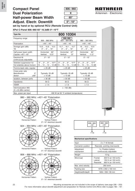
Compact Panel<br />
Dual Polarization<br />
Half-power Beam Width<br />
Adjust. Electr. Downtilt<br />
806–960<br />
0°– 10°<br />
set by hand or by optional RCU (Remote Control Unit)<br />
XPol C-Panel 806–960 65° 16.3dBi 0°–10°T<br />
Type No.<br />
X<br />
65°<br />
800 10304<br />
Frequency range<br />
806–960<br />
806 – 866 <strong>MHz</strong> 824 – 894 <strong>MHz</strong> 880 – 960 <strong>MHz</strong><br />
Polarization +45°, –45° +45°, –45 +45°, –45°<br />
Average gain (dBi) 15.6 ... 15.8 ... 15.5 15.7 ... 16.1 ... 15.7 16 ... 16.3 ... 15.9<br />
Tilt 0° ... 5° ... 10° 0° ... 5° ... 10° 0° ... 5° ... 10°<br />
Half-power beam width Horizontal: 69° Horizontal: 67° Horizontal: 65°<br />
Copolar +45°/ –45° Vertical: 12.5° Vertical: 12° Vertical: 11.5°<br />
Electrical tilt 0°– 10° 0°– 10° 0°– 10°<br />
continuously adjustable<br />
Sidelobe suppression for 0° ... 3° ... 6° ... 10°T 0° ... 3° ... 6° ... 10°T 0° ... 3° ... 6° ... 10°T<br />
first sidelobe above horizon 15 ... 14 ... 12 ... 12 dB 15 ... 15 ... 15 ... 14 dB 15 ... 15 ... 15 ... 14 dB<br />
Front-to-back ratio, copolar > 25 dB > 25 dB > 25 dB<br />
Cross polar ratio<br />
Maindirection 0° Typically: 25 dB Typically: 25 dB Typically: 25 dB<br />
Sector ±60° > 10 dB > 10 dB > 10 dB<br />
Isolation, between ports > 30 dB > 30 dB > 30 dB<br />
Impedance 50 Ω 50 Ω 50 Ω<br />
VSWR < 1.5 < 1.5 < 1.5<br />
Intermodulation IM3<br />
< –150 dBc<br />
(2 x 43 dBm carrier)<br />
Max. power per input<br />
400 W (at 50 °C ambient temperature)<br />
880 – 960 <strong>MHz</strong>: +45°/–45° Polarization<br />
122°<br />
65°<br />
11.5°<br />
10<br />
10<br />
3<br />
3<br />
0<br />
Horizontal Pattern<br />
0<br />
Vertical Pattern<br />
0°–10° electrical downtilt<br />
824 – 894 <strong>MHz</strong>: +45°/–45° Polarization<br />
806–960<br />
–45°<br />
806–960<br />
+45°<br />
130°<br />
67°<br />
12°<br />
7-16 7-16<br />
10<br />
10<br />
Mechanical specifications<br />
3<br />
0<br />
Horizontal Pattern<br />
10<br />
3<br />
0<br />
135°<br />
69°<br />
Horizontal Pattern<br />
3<br />
0<br />
Vertical Pattern<br />
0°–10° electrical downtilt<br />
806 – 866 <strong>MHz</strong>: +45°/–45° Polarization<br />
10<br />
3<br />
0<br />
12.5°<br />
Vertical Pattern<br />
0°–10° electrical downtilt<br />
Input<br />
2 x 7-16 female<br />
Connector position Rearside, pointing downwards<br />
Adjustment<br />
1x, Position bottom<br />
mechanism<br />
continuously adjustable<br />
Weight<br />
13 kg<br />
Wind load Frontal: 300 N (at 150 km/h)<br />
Lateral: 195 N (at 150 km/h)<br />
Rearside: 660 N (at 150 km/h)<br />
Max. wind velocity<br />
200 km/h<br />
Packing size<br />
1976 x 292 x 192 mm<br />
Height/width/depth<br />
1694 / 259 / 99 mm<br />
22 Mounting accessories are not included in the scope of delivery (see page 228 – 233)<br />
For more information about downtilt adjustment and preparation for Remote Control Unit (RCU) refer to pages 182 – 191