99810492; 790-6000 MHz Base Station Antennas - Romkatel
99810492; 790-6000 MHz Base Station Antennas - Romkatel
99810492; 790-6000 MHz Base Station Antennas - Romkatel

You also want an ePaper? Increase the reach of your titles
YUMPU automatically turns print PDFs into web optimized ePapers that Google loves.
dB<br />
dB<br />
dB<br />
dB<br />
dB<br />
dB<br />
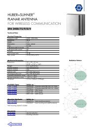
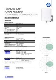
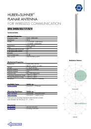
Tri-Sector Pipe Antenna<br />
Frequency Range<br />
Dual Polarization<br />
Half-power Beam Width<br />
Adjust. Electr. Downtilt<br />
0° 120° 240°<br />
1710–2170<br />
1710–2170<br />
0°–12° 0°–12°<br />
set by hand or by optional RCUs (Remote Control Units)<br />
X<br />
65°<br />
X<br />
65°<br />
1710–2170<br />
X<br />
65°<br />
0°–12°<br />
XPol Tri-Sector Pipe 1710–2170 65° 15.5dBi 0°–12°T<br />
Type No.<br />
Frequency range<br />
Electrical datas<br />
800 10375 per sector<br />
1710–2170<br />
1710 – 1880 <strong>MHz</strong> 1850 – 1990 <strong>MHz</strong> 1920 – 2170 <strong>MHz</strong><br />
Polarization +45°, –45° +45°, –45° +45°, –45°<br />
Gain 0° ... 4° ... 8° … 12° T 0° ... 4° ... 8° … 12° T 0° ... 4° ... 8° … 12° T<br />
per Input (dBi) 15.4 ... 15.2 ... 15.0 ... 14.8 15.5 ... 15.4 ... 15.3 ... 14.9 15.7 ... 15.6 ... 15.4 ... 14.9<br />
Half-power beam width Horizontal: 67° Horizontal: 65° Horizontal: 62°<br />
Copolar +45°/ –45° Vertical: 12.7° Vertical: 12° Vertical: 11.2°<br />
Electrical tilt 0°–12° 0°–12° 0°–12°<br />
continuously adjustable<br />
Sidelobe suppression for 0° ... 4° ... 8° … 12° T 0° ... 4° ... 8° … 12° T 0° ... 4° ... 8° … 12° T<br />
first sidelobe above horizon 16 ... 16 ... 15 ... 15 dB 18 ... 17 ... 17 ... 16 dB 18 ... 18 ... 16 ... 16 dB<br />
Front-to-back ratio Copolar: > 25 dB Copolar: > 25 dB Copolar: > 25 dB<br />
Cross polar ratio<br />
Maindirection 0° Typically: 20 dB Typically: 20 dB Typically: 20 dB<br />
Sector ±60° Typically: > 10 dB Typically: > 10 dB Typically: > 10 dB<br />
Isolation: Intrasystem > 30 dB > 30 dB > 30 dB<br />
Isolation: Intersystem > 40 dB > 40 dB > 40 dB<br />
Impedance 50 Ω 50 Ω 50 Ω<br />
VSWR < 1.5 < 1.5 < 1.5<br />
Intermodulation IM3<br />
< –150 dBc<br />
(2 x 43 dBm carrier)<br />
Max. power per input<br />
250 W (at 50 °C ambient temperature)<br />
compact<br />
service area<br />
0°<br />
7-16 7-16<br />
Tri-Sector<br />
Pipe Antenna<br />
1710 – 1880 <strong>MHz</strong>: +45°/–45° Polarization<br />
+45°<br />
–45°<br />
1710 –2170<br />
130°<br />
67°<br />
12.7°<br />
7-16<br />
–45°<br />
+45°<br />
1710 –2170 1710 –2170<br />
7-16<br />
10<br />
3<br />
10<br />
3<br />
240°<br />
+45°<br />
7-16<br />
–45°<br />
7-16<br />
120°<br />
0<br />
Horizontal Pattern<br />
10<br />
3<br />
0<br />
125°<br />
65°<br />
0<br />
Vertical Pattern<br />
0°–12° electrical downtilt<br />
1850 – 1990 <strong>MHz</strong>: +45°/–45° Polarization<br />
Horizontal Pattern Vertical Pattern<br />
0°–12° electrical downtilt<br />
1920 – 2170 <strong>MHz</strong>: +45°/–45° Polarization<br />
10<br />
3<br />
0<br />
118°<br />
62°<br />
Horizontal Pattern<br />
10<br />
3<br />
0<br />
10<br />
3<br />
0<br />
12°<br />
11.2°<br />
Vertical Pattern<br />
0°–12° electrical downtilt<br />
Mechanical specifications<br />
Input<br />
3 x 2 x 7-16 female<br />
Connector position Bottom – inside service area<br />
Adjustment<br />
3 x 1, Position bottom<br />
mechanism<br />
continuously adjustable<br />
inside service area<br />
Weight<br />
32 kg<br />
Wind load<br />
205 N (at 150 km/h)<br />
Max. wind velocity<br />
200 km/h<br />
Natural frequency<br />
45 – 47 Hz<br />
Damping ratio 0.032<br />
Mechanical interface Flange connection 12 x 12M<br />
at a graduated diameter of 208 mm<br />
0°–360° continuously adjustable<br />
(for further details<br />
see application note)<br />
Packing size<br />
1395 x 315 x 330 mm<br />
Height/ diameter<br />
1241 / 230 and 280 mm<br />
Mounting accessories are not included in the scope of delivery (see page 236 – 239)<br />
For more information about downtilt adjustment and preparation for Remote Control Unit (RCU) refer to pages 182 – 191<br />
107