Basic WAN Concepts - Router Alley
Basic WAN Concepts - Router Alley
Basic WAN Concepts - Router Alley

Create successful ePaper yourself
Turn your PDF publications into a flip-book with our unique Google optimized e-Paper software.
<strong>Basic</strong> <strong>WAN</strong> <strong>Concepts</strong> v1.15 – Aaron Balchunas<br />
1<br />
What is a <strong>WAN</strong>?<br />
- <strong>Basic</strong> <strong>WAN</strong> <strong>Concepts</strong> -<br />
There are two prevailing definitions of a Wide Area Network (<strong>WAN</strong>). The<br />
book definition of a <strong>WAN</strong> is a network that spans large geographical<br />
locations, usually to interconnect multiple Local Area Networks (LANs).<br />
The practical definition of a <strong>WAN</strong> is a network that traverses a public<br />
network or commercial carrier, using one of several <strong>WAN</strong> technologies.<br />
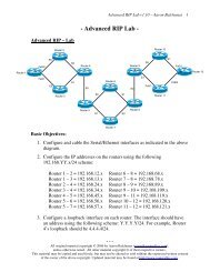
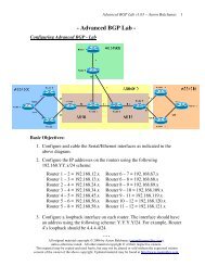
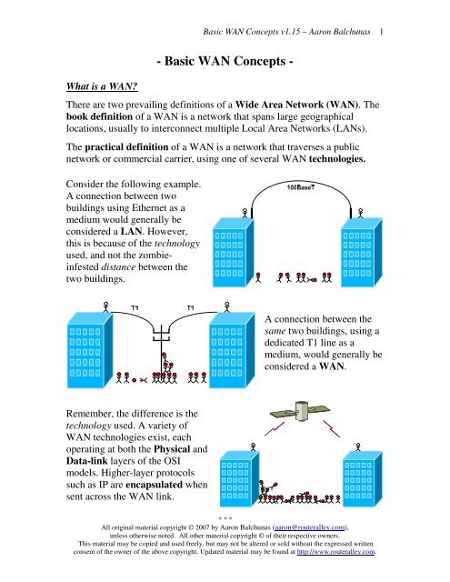
Consider the following example.<br />
A connection between two<br />
buildings using Ethernet as a<br />
medium would generally be<br />
considered a LAN. However,<br />
this is because of the technology<br />
used, and not the zombieinfested<br />
distance between the<br />
two buildings.<br />
A connection between the<br />
same two buildings, using a<br />
dedicated T1 line as a<br />
medium, would generally be<br />
considered a <strong>WAN</strong>.<br />
Remember, the difference is the<br />
technology used. A variety of<br />
<strong>WAN</strong> technologies exist, each<br />
operating at both the Physical and<br />
Data-link layers of the OSI<br />
models. Higher-layer protocols<br />
such as IP are encapsulated when<br />
sent across the <strong>WAN</strong> link.<br />
* * *<br />
All original material copyright © 2007 by Aaron Balchunas (aaron@routeralley.com),<br />
unless otherwise noted. All other material copyright © of their respective owners.<br />
This material may be copied and used freely, but may not be altered or sold without the expressed written<br />
consent of the owner of the above copyright. Updated material may be found at http://www.routeralley.com.
<strong>Basic</strong> <strong>WAN</strong> <strong>Concepts</strong> v1.15 – Aaron Balchunas<br />
2<br />
<strong>WAN</strong> Connection Types<br />
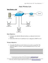
<strong>WAN</strong>s are generally grouped into three separate connection types:<br />
• Point-to-Point technologies<br />
• Circuit-switched technologies<br />
• Packet-switched technologies<br />
Point-to-Point technologies (often called dedicated or leased lines) are<br />
usually the most expensive form of <strong>WAN</strong> technology. Point-to-Point<br />
technologies are leased from a service provider, and provide guaranteed<br />
bandwidth from location to another (hence point-to-point). Cost is<br />
determined by the distance of the connection, and the amount of bandwidth<br />
allocated.<br />
Generally, point-to-point links require no call-setup, and the connection is<br />
usually always on. Examples of point-to-point technologies include:<br />
• T1 lines<br />
• T3 lines<br />
Circuit-Switched technologies require call-setup to occur before<br />
information can be transferred. The session is usually torn down once data<br />
transfer is complete (this is identified as an On-Demand Circuit). Circuitswitched<br />
lines are generally low-speed compared to point-to-point lines.<br />
Examples of circuit-switched technologies include:<br />
• Dial-up<br />
• ISDN<br />
Packet-Switched technologies share a common infrastructure between all<br />
the provider’s subscribers. Thus, bandwidth is not guaranteed, but is instead<br />
allocated on a best effort basis. Packet-switched technologies are ill-suited<br />
for applications that require consistent bandwidth, but are considerably less<br />
expensive than dedicated point-to-point lines.<br />
Examples of packet-switched technologies include:<br />
• Frame-Relay<br />
• X25<br />
(Reference: http://www.cisco.com/univercd/cc/td/doc/cisintwk/ito_doc/introwan.htm<br />
http://www.ciscopress.com/content/images/chap01_1587051486/elementLinks/1587051486content.pdf)<br />
* * *<br />
All original material copyright © 2007 by Aaron Balchunas (aaron@routeralley.com),<br />
unless otherwise noted. All other material copyright © of their respective owners.<br />
This material may be copied and used freely, but may not be altered or sold without the expressed written<br />
consent of the owner of the above copyright. Updated material may be found at http://www.routeralley.com.
<strong>Basic</strong> <strong>WAN</strong> <strong>Concepts</strong> v1.15 – Aaron Balchunas<br />
3<br />
Common <strong>WAN</strong> Terms<br />
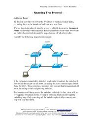
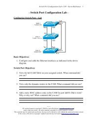
A wide variety of hardware is used with <strong>WAN</strong>s. Equipment that is housed at<br />
the subscriber is referred to as Customer Premise Equipment (CPE).<br />
The above example demonstrates the basic equipment required for a T1 line.<br />
A CSU/DSU (Channelized Service Unit/Data Service Unit) provides the<br />
clocking and channelization for T1 or T3 technology. The CSU/DSU<br />
converts the signal for use on an Ethernet (or other LAN technology)<br />
network. If a <strong>WAN</strong> technology other than a T1 line is used, a different<br />
device will be required. Examples include (but are no limited to):<br />
• ISDN – a terminal adapter<br />
• Dialup – a modem<br />
The Demarc (short for demarcation) refers to the point of last responsibility<br />
for the service provider. All equipment on the Customer Premises side of the<br />
Demarc is the customer’s responsibility to maintain. The Demarc is not<br />
always physically labeled or identifiable. Occasionally, a two-port or fourport<br />
patch-panel will be used as a physical Demarc.<br />
The Smart Jack physically terminates the T1 line. If there is a connectivity<br />
issue, the provider will perform a ping test to the smart jack. If<br />
communication to the smart jack is successful, the provider will assume the<br />
issue resides on the customer’s side of responsibility. The smart jack is often<br />
locked in a glass enclosure, and labeled with the T1’s circuit number.<br />
The Local Loop (or Last Mile) refers to the physical line connecting from<br />
the Customer Premises to the provider’s nearest Central Office (CO).<br />
* * *<br />
All original material copyright © 2007 by Aaron Balchunas (aaron@routeralley.com),<br />
unless otherwise noted. All other material copyright © of their respective owners.<br />
This material may be copied and used freely, but may not be altered or sold without the expressed written<br />
consent of the owner of the above copyright. Updated material may be found at http://www.routeralley.com.
<strong>Basic</strong> <strong>WAN</strong> <strong>Concepts</strong> v1.15 – Aaron Balchunas<br />
4<br />
<strong>WAN</strong> Encapsulation<br />
Recall that <strong>WAN</strong> technologies operate at both Physical and Data-link<br />
layers of the OSI models, and that higher-layer protocols such as IP are<br />
encapsulated when sent across the <strong>WAN</strong> link.<br />
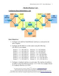
A <strong>WAN</strong> is usually terminated on a Cisco device’s serial interface. Serial<br />
interfaces support a wide variety of <strong>WAN</strong> encapsulation types, which must<br />
be manually specified.<br />
By default, a serial interface will utilize HDLC for encapsulation. Other<br />
supported encapsulation types include:<br />
• SDLC<br />
• PPP<br />
• LAPB<br />
• Frame-Relay<br />
• X.25<br />
• ATM<br />
Regardless of the <strong>WAN</strong> encapsulation used, it must identical on both sides<br />
of a point-to-point link.<br />
Each encapsulation type is described in detail in separate guides.<br />
* * *<br />
All original material copyright © 2007 by Aaron Balchunas (aaron@routeralley.com),<br />
unless otherwise noted. All other material copyright © of their respective owners.<br />
This material may be copied and used freely, but may not be altered or sold without the expressed written<br />
consent of the owner of the above copyright. Updated material may be found at http://www.routeralley.com.