Re-building an HP20 Engine - Part 2 - The Enthusiasts Website for ...
Re-building an HP20 Engine - Part 2 - The Enthusiasts Website for ...
Re-building an HP20 Engine - Part 2 - The Enthusiasts Website for ...

You also want an ePaper? Increase the reach of your titles
YUMPU automatically turns print PDFs into web optimized ePapers that Google loves.
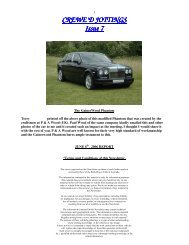
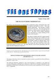
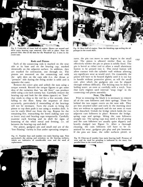
Fig. 9. Underside of front half of engine. Shown are second <strong>an</strong>d<br />
third main bearing caps removed, first still in place. Note the<br />
general filth. One of the slots <strong>for</strong> the Woodruff key is seen in the<br />
cr<strong>an</strong>k nose.<br />
Rods <strong>an</strong>d Pistons<br />
Each of the connecting rods is marked on the near<br />
side at its base <strong>an</strong>d on the bearing cap, marked<br />
identically on the adjacent surface. In addition, they<br />
are marked <strong>for</strong> orientation, one through six. <strong>The</strong><br />
pistons are mounted on the connecting rod with<br />
the split skirt on the cam side (i.e. the thrust or<br />
"pressure" side during the firing stroke is solid <strong>an</strong>d is<br />
opposite the cam).<br />
<strong>Re</strong>move the cotter pins <strong>an</strong>d unbolt the nuts using a<br />
torque wrench. <strong>Re</strong>cord the torque figures to get some<br />
idea of the variation that "<strong>an</strong> old fitter" c<strong>an</strong> produce<br />
while using a six-inch tommy bar. Carefully remove the<br />
bearing cap <strong>an</strong>d look <strong>for</strong> the shims (spacer) or "liner"<br />
that tends to cling to the rod <strong>for</strong> a few seconds, then<br />
falling to the floor. Keep the sequence of these<br />
accurately, particularly if remetalling of the bearings<br />
will not be necessary. Turn the cr<strong>an</strong>k to bring the<br />
piston to top then push it out using a wooden drift. It<br />
c<strong>an</strong> be easily lifted out from the top. <strong>Re</strong>peat <strong>for</strong> the<br />
remaining five, reattaching the liners (taking care not<br />
to invert <strong>an</strong>y) <strong>an</strong>d bearing caps temporarily. Carefully<br />
examine each bearing <strong>an</strong>d its shell <strong>for</strong> signs of<br />
loosening of the white metal <strong>an</strong>d fretting, i.e. oil<br />
between the bearing cap <strong>an</strong>d shell.<br />
<strong>The</strong> piston, gudgeon pin <strong>an</strong>d small end are of the<br />
"free floating" variety in that under operating tempera-<br />
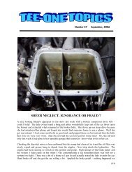
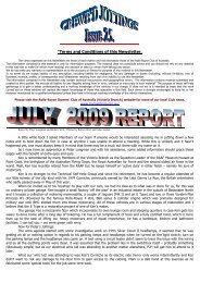
Fig. 11. Number four <strong>an</strong>d number two main bearing caps. Note<br />
particularly the pitting <strong>an</strong>d striations on the bearing surfaces,<br />
which are indicative of considerable wear <strong>an</strong>d the need of<br />
replacement.<br />
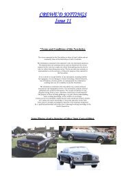
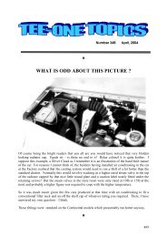
Fig. 10. <strong>Re</strong>ar half of engine. Note the bl<strong>an</strong>king caps sealing the oil<br />
passages in the cr<strong>an</strong>k shaft.<br />
tures, the pin c<strong>an</strong> move to some degree in the small<br />
end. <strong>The</strong> piston is allowed similar float so that<br />
effectively neither the pin or piston is solidly fixed. <strong>The</strong><br />
pin is bored at either end to allow a small aluminum<br />
button to be pressed into it. This metal button will<br />
allow contact with the cylinder wall without allowing<br />
<strong>an</strong>y signific<strong>an</strong>t wear as would steel. On reassembly the<br />
piston will have to be heated slightly until it is too hot<br />
to h<strong>an</strong>dle without protective gloves, as will the small<br />
end, after which the gudgeon pin c<strong>an</strong> be slipped<br />
through without difficulty. <strong>The</strong> heating may be done in<br />
boiling water, <strong>an</strong> oven or carefully with a torch. Note<br />
that early engines used internal "snap rings" in the<br />
connecting rod-piston assembly.<br />
Next, <strong>The</strong> Block<br />
Prior to removing the block it is necessary to remove<br />
all of the cam followers <strong>an</strong>d their springs. <strong>The</strong>se live<br />
behind the two tappet covers on the near side. <strong>The</strong>y<br />
are best attacked sober <strong>an</strong>d early in the morning since<br />
they are tedious to approach <strong>an</strong>d do not seem to w<strong>an</strong>t<br />
to be disturbed. Unbolt the bridge which holds the two<br />
adjacent cam followers in place. <strong>Re</strong>move the bridge,<br />
spring caps <strong>an</strong>d springs, lifting the cam followers<br />
straight out. <strong>The</strong> spring caps may need a bit of prying<br />
<strong>an</strong>d the cam followers are usually quite slippery <strong>an</strong>d<br />
heavily sludged (see Figure 5). After a thorough<br />
cle<strong>an</strong>ing, the cam followers will have to be examined<br />
<strong>for</strong> wear, gudgeon pin play <strong>an</strong>d pin looseness.<br />
If the pins are loose, the roller surfaces pitted, or<br />
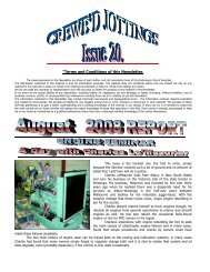
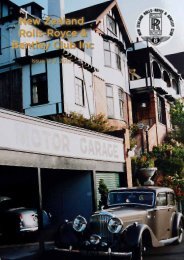
Fig. 12. Close-up of number four main bearing itself. Presence of<br />
wear <strong>an</strong>d the need <strong>for</strong> grinding is indicated by the m<strong>an</strong>y fine<br />
parallel lines in the cr<strong>an</strong>k surface.<br />
1757