Technical Specifications - R.S. Engineering and Manufacturing
Technical Specifications - R.S. Engineering and Manufacturing
Technical Specifications - R.S. Engineering and Manufacturing

Create successful ePaper yourself
Turn your PDF publications into a flip-book with our unique Google optimized e-Paper software.
ISA Series<br />
Installed<br />
Sound<br />
Amplifiers<br />
User Manual<br />
n ISA 300T<br />
n ISA 500T<br />
n ISA 800T<br />
n ISA 280<br />
n ISA 450<br />
n ISA 750<br />
ISA Audio Power Amplifiers<br />
*TD-000093-00*<br />
TD-000093-00 rev.C
IMPORTANT SAFETY PRECAUTIONS<br />
& EXPLANATION OF SYMBOLS<br />
CAUTION<br />
RISK OF ELECTRIC SHOCK<br />
DO NOT OPEN<br />
CAUTION: TO REDUCE THE RISK OF ELECTRIC<br />
SHOCK, DO NOT REMOVE THE COVER. NO USER-<br />
SERVICEABLE PARTS INSIDE. REFER SERVICING<br />
TO QUALIFIED PERSONNEL.<br />
The lightning flash with arrowhead symbol within an equilateral triangle is intended to alert the user to the<br />
presence of uninsulated “dangerous” voltage within the product’s enclosure that may be of sufficient<br />
magnitude to constitute a risk of electric shock to humans.<br />
The exclamation point within an equilateral triangle is intended to alert the user to the<br />
presence of important operating <strong>and</strong> maintenance (servicing) instructions in this manual.<br />
The lightning flashes printed next to the OUTPUT terminals of all ISA amplifiers are intended to alert the user<br />
to the risk of hazardous energy. Output connectors that could pose a risk are marked with the lightning flash.<br />
Do not touch output terminals while amplifier power is on. Make all connections with amplifier turned off.<br />
WARNING: TO PREVENT FIRE OR ELECTRIC SHOCK, DO NOT EXPOSE THIS<br />
EQUIPMENT TO RAIN OR MOISTURE.<br />
This amplifier has a serial number located on the rear panel.<br />
Please write this <strong>and</strong> the model number down <strong>and</strong> keep them for your records.<br />
Model: ISA ________________________________<br />
Serial Number:______________________________<br />
Date of Purchase:____________________________<br />
Purchased From:_____________________________<br />
FCC INTERFERENCE STATEMENT<br />
NOTE: This equipment has been tested <strong>and</strong> found to comply with the limits for a class B digital device, pursuant to part<br />
15 of the FCC rules. These limits are designed to provide reasonable protection against harmful interference in a<br />
residential installation. This equipment generates, uses, <strong>and</strong> can radiate radio frequency energy <strong>and</strong> if not installed<br />
<strong>and</strong> used in accordance to the instructions , may cause harmful interference to radio communications. However, there<br />
is no guarantee that interference will not occur in a particular installation. If this equipment does cause harmful<br />
interference to radio or television reception, which can be determined by switching the equipment off <strong>and</strong> on, the user<br />
is encouraged to try to correct the interference by one or more of the following measures:<br />
- Reorient or relocate the receiving antenna.<br />
- Increase the separation between the equipment <strong>and</strong> the receiver.<br />
- Connect the equipment into an outlet on a circuit different from that to which the receiver is connected.<br />
- Consult the dealer or an experienced radio or TV technician for help.<br />
2<br />
© Copyright 2000, QSC Audio Products, Inc.<br />
QSC® is a registered trademark of QSC Audio Products, Inc.<br />
“QSC” <strong>and</strong> the QSC logo are registered with the U.S. Patent <strong>and</strong> Trademark Office<br />
The Audio Precision logo is the property of Audio Precision, Beaverton OR<br />
All trademarks are the property of their respective owners.
TABLE OF CONTENTS<br />
INTRODUCTION:<br />
ISA Series Overview .......................................................................................4<br />
Front Panel Illustration .........................................................................................4<br />
Rear Panel Illustrations ........................................................................................5<br />
FEATURES & SETUP :<br />
Power Switch ............................................................................................6<br />
Cooling Air Inlet <strong>and</strong> Exhaust Vents ...............................................................6<br />
LED Indicators ........................................................................................7<br />
Gain Controls ........................................................................................8<br />
Input Jacks ..........................................................................................8<br />
DataPort V2 Connector ...................................................................................9<br />
Daisy Chaining to Other Devices from the DataPort V2 ................................9<br />
Stereo & Parallel Operating Modes ..................................................................10<br />
DIP Switch Settings ...................................................................11<br />
Bridge Mono Operating Mode .......................................................................12<br />
DIP Switch Settings ................................................................12<br />
Low Frequency Filter ..........................................................................13<br />
DIP Switch Settings ..............................................................13<br />
Frequency Response Curves ..................................................................14<br />
Clip Limiter ........................................................................................15<br />
DIP Switch Settings ...............................................................15<br />
INSTALLATION:<br />
Rack Mounting ....................................................................................16<br />
Mounting Dimensions .........................................................................16<br />
Cooling Requirements ........................................................................17<br />
AC Mains (AC Power) ..............................................................................17<br />
CONNECTIONS:<br />
Inputs: XLR <strong>and</strong> Terminal Block Input Jacks ...............................................18<br />
Inputs: DataPort V2 Connections <strong>and</strong> Notes ...........................................19<br />
Outputs: Using the Screw Terminal Connections ............................................20<br />
Outputs: Direct Low Impedance (2-16 ohm loads) ................................................21<br />
Outputs: Distributed High Impedance (“T” models only) ..................................22<br />
Power Sharing Between High <strong>and</strong> Low Impedance Outputs (“T” models only) .......24<br />
Securing Output Wiring to the Chassis .................................................................25<br />
OPERATION:<br />
Gain Controls .........................................................................................................26<br />
AC Power Switch .........................................................................................26<br />
Front Panel LED Indicators ................................................................................26<br />
Normal Operating Levels ......................................................................................26<br />
APPLICATIONS:<br />
General Notes, Distributed Line Principles .....................................................27<br />
Low Frequency Filtering, Distributed Output Examples ........................................28<br />
Multiple Low Impedance Loads in Series or Parallel Connections .........................30<br />
DataPort V2 Application Information ...........................................................................32<br />
TROUBLESHOOTING ........................................................................................................33<br />
SPECIFICATIONS ......................................................................................................35<br />
WARRANTY INFORMATION .............................................................................................39<br />
HOW TO CONTACT QSC AUDIO PRODUCTS ............................................................................39<br />
3
INTRODUCTION- INTRODUCTION AND FRONT PANEL ILLUSTRATION<br />
Thank you for the purchase of your new ISA amplifier. To get<br />
the most out of your amplifier, review this manual carefully. The<br />
installation, connection <strong>and</strong> operation sections provide useful<br />
guidelines to get you up <strong>and</strong> running quickly <strong>and</strong> correctly.<br />
The QSC shipping box should contain:<br />
1- The amplifier<br />
2- This user manual<br />
3- #14AWG AC line cord with IEC connector<br />
After you have removed the amplifier from the box, make sure<br />
you save the box <strong>and</strong> packing material for safely storing or<br />
shipping the amplifier in the future.<br />
The ISA Series amplifiers offer professional-quality performance<br />
at an affordable price. Three power-points are offered in<br />
both directly-coupled <strong>and</strong> autotransformer-coupled output.<br />
Output power at 2 ohms ranges from 430 to 1200 watts per<br />
channel.<br />
The ISA amplifier was designed to fit your installed sound<br />
requirements. The detented gain controls, located on the rear<br />
panel, provide accurate, repeatable adjustments. Each channel<br />
has defeatable clip limiting <strong>and</strong> selectable-response low<br />
frequency filters. QSC’s rear-to-front airflow cooling helps to<br />
keep other system components in the equipment rack cooler,<br />
enhancing overall system reliability.<br />
For those systems with QSC DataPort accessories (DSP,<br />
crossovers & filters, remote cinema monitoring) a DataPort V2<br />
(version 2) is included on all ISA models. Consult your QSC<br />
representative for accessory compatibility information.<br />
The ISA amplifiers are easy to use. All operating mode<br />
switches are grouped together on the rear panel. A mode<br />
switch configuration chart is printed directly on the rear panel for<br />
easy, accurate reference. This helps to avoid configuration<br />
problems. On the autotransformer-coupled “T” models, separate<br />
screw-terminal output connections are provided for both low<br />
impedance loads <strong>and</strong> high impedance (25/70/100 volt) loads.<br />
The “connectability” of the “T” models makes them simple to<br />
use in almost any installed sound application.<br />
The ISA amplifiers are built for long service life. XLR <strong>and</strong><br />
terminal block input connectors provide tight, noise-free<br />
connections. The chassis design incorporates robust output<br />
cable dressing tie-down points to keep stress off the connections,<br />
making them more reliable. All signal processing is done in<br />
side loops <strong>and</strong> then returned to the main signal path. This<br />
maintains high signal fidelity <strong>and</strong> provides a more robust system.<br />
Your new ISA amplifier will give you many years of great<br />
sound. It is the best value in installed sound amplification with<br />
legendary QSC durability <strong>and</strong> performance.<br />
FRONT PANEL<br />
(all models)<br />
4<br />
1. Power indicator LED<br />
2. Power switch<br />
3. Clip <strong>and</strong> Signal indicator LEDs<br />
4. Cooling air exhaust vents<br />
5. Mounting holes for optional h<strong>and</strong>les<br />
6. Mounting holes for rack mounting
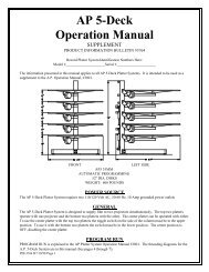
INTRODUCTION- REAR PANEL ILLUSTRATIONS<br />
REAR PANEL<br />
ISA 280<br />
ISA 450<br />
ISA 750<br />
1. Gain Controls<br />
2. Terminal Block Inputs<br />
3. DataPort V2 Connector<br />
4. XLR Inputs<br />
5. Mode Switches<br />
6. Mode Switch Configuration Charts<br />
7. Cooling Air Inlet Vent<br />
8. Output Connections, Low Impedance<br />
9. Serial Number Label<br />
10. Circuit Breaker for AC Power<br />
11. Tabs for Securing Output Wires<br />
12. AC Power Connector, IEC type<br />
NOTE! Output connection terminals shown without protective cover in place for clarity (rear panel, above & below).<br />
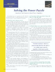
REAR PANEL<br />
ISA 300T<br />
ISA 500T<br />
ISA 800T<br />
1. Gain Controls<br />
2. Terminal Block Inputs<br />
3. DataPort V2 Connector<br />
4. XLR Inputs<br />
5. Mode Switches<br />
6. Mode Switch Configuration Charts<br />
7. Cooling Air Inlet Vent<br />
8. Output Connections, Low Impedance<br />
9. Serial Number Label<br />
10. Output Connections, Distributed (high impedance)<br />
11. Circuit Breaker for AC Power<br />
12. Tabs for Securing Output Wires<br />
13. AC Power Connector, IEC type<br />
5
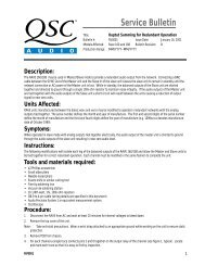
FEATURES & SETUP- POWER SWITCH, COOLING AIR VENTS<br />
The front panel of ISA series amplifiers is tailored for installed<br />
sound. The power switch is the only front panel control; gain<br />
controls are located on the rear panel to minimize control<br />
tampering. LED indicators are provided for power, input signal<br />
<strong>and</strong> to warn of clipping.<br />
POWER SWITCH-<br />
The power switch is a rocker-type switch. To turn the amplifier<br />
on, push in on the top portion of the switch. To turn the amplifier<br />
off, push in on the bottom portion of the switch.<br />
The green power LED should light up when the switch is in the<br />
on position.<br />
When the power is switched off, the LED may takes several<br />
seconds to go out; this is normal.<br />
If the POWER LED fails to illuminate when the switch is in the ON position:<br />
1- Check the AC cord <strong>and</strong> insure that both ends are fully inserted into their receptacles. If the power LED<br />
still fails to illuminate,<br />
2- Check the AC outlet for voltage with a circuit tester or known good device (lamp, etc.).<br />
3- Check the AC circuit breaker on the rear panel of the amplifier. The illustration at the right shows the<br />
circuit breaker in its normal (operating) position <strong>and</strong> its tripped position (amplifier AC power turned off by<br />
protective circuit breaker).<br />
NOTE! It is normal for the circuit breaker to open if the<br />
amplifier is operated continuously at output levels at or<br />
exceeding specified power levels.<br />
Rear panel circuit breaker:<br />
Normal operating position<br />
If the circuit breaker opens repeatedly with nothing<br />
connected to the amplifier <strong>and</strong> it is connected to the<br />
proper AC source as labeled on the rear panel serial<br />
number label, then the amplifier requires servicing.<br />
Rear panel circuit breaker:<br />
Tripped or open position;<br />
press to reset.<br />
COOLING AIR INLET AND EXHAUST VENTS-<br />
Keep the inlet <strong>and</strong> exhaust air vents clear of any obstructions. Insure<br />
that the air exhausted from the vents has an exit from the equipment<br />
enclosure.<br />
Equipment enclosures with insufficient air flow will cause amplifier<br />
overheating. Enclosures must allow fresh air to enter <strong>and</strong> hot air to<br />
exit.<br />
6<br />
If dust builds up, clogging the vents, use a soft brush <strong>and</strong> a vacuum<br />
cleaner to remove the dust. Use the brush to loosen the dust while the<br />
vacuum is used to pull the dust away from the amplifier.
FEATURES & SETUP- LED INDICATORS<br />
POWER: green LED that illuminates when the power<br />
switch is set to the on position <strong>and</strong> AC power is present<br />
at the IEC cord receptacle.<br />
Normal indication: at power-on the LED will illuminate<br />
at half-brightness for 2-3 seconds, then it illuminates<br />
to full-brightness.<br />
If no indication: see previous page for suggested<br />
items to check.<br />
When power is switched off: the LED may take<br />
several seconds to extinguish (go out); this is normal.<br />
SIGNAL: green LED that lights up when the input<br />
signal is strong enough to drive the output to about -40<br />
dB from rated 8-ohm power.<br />
Normal indication: varying brightness corresponding<br />
to strength of input signal.<br />
If no indication: check gain settings, input cables,<br />
connections <strong>and</strong> audio source. If audio source is<br />
extremely low signal strength, signal LED may not<br />
illuminate; this is normal but indicates that the input<br />
signal strength should be increased.<br />
Occasional illumination: normal for weak input<br />
signal strength.<br />
Illuminated dimly all the time with brighter<br />
flashing: normal for “average” input signal strength.<br />
Fully illuminated (on): normal for “pushing” the<br />
amplifier hard. Also, the clip indicator will probably<br />
flash dimly with the beat of the program material <strong>and</strong><br />
brightly during extreme peaks in the material.<br />
CLIP : red LED that illuminates when the amplifier<br />
clips.<br />
Normal indication: illumination briefly at extreme<br />
output power peaks. Occasional clipping (once briefly<br />
every few seconds) when operation at high power<br />
levels is normal. At power-on, the clip LEDs may briefly<br />
flash; this is normal.<br />
Continuous operation at high power may trigger the<br />
thermal protection circuitry, shutting down the amplifier<br />
<strong>and</strong> fully illuminating the clip LED. Operation will<br />
resume after the amplifier has cooled down sufficiently.<br />
If no indication: normal if the amplifier is operated at<br />
very low output levels.<br />
Occasional illumination: Occasional clipping (once<br />
briefly every few seconds) when operation at high<br />
power levels is normal. Continuous operation at high<br />
power may trigger the thermal protection circuitry,<br />
shutting down the amplifier <strong>and</strong> fully illuminating the<br />
clip LED.<br />
Illuminated most of the time: Not normal; reduce the<br />
output of the amplifier <strong>and</strong>/or input signal to avoid<br />
thermal shutdown of the amplifier <strong>and</strong> possible speaker<br />
damage.<br />
Fully illuminated (on): Amplifier is in thermal shut<br />
down. Reduce gain settings or input signal <strong>and</strong> allow<br />
the amp to cool down. Leave the power on so that the<br />
fan continues to run; operation will automatically<br />
resume after the amplifier has cooled sufficiently.<br />
7
FEATURES & SETUP- GAIN CONTROLS & INPUT JACKS<br />
GAIN CONTROLS-<br />
WHERE THEY ARE-<br />
The Gain controls are located on the rear panel to minimize<br />
control tampering after installation. When viewing the amplifier<br />
from the rear, they are on the left end, top <strong>and</strong> bottom, as shown<br />
in the illustration to the right.<br />
The Gain controls are detented (11 steps) for repeatable<br />
adjustment. Surrounding the Gain control, the power attenuation<br />
level is shown in dB. To operate the Gain control, rotate the<br />
control’s knob so that the desired level is achieved. There is a<br />
detent in the knob to indicate its position.<br />
Maximum gain depends on the model, see chart, below.<br />
MAXIMUM VOLTAGE GAIN BY MODEL<br />
ISA 280, 300T<br />
ISA 450, 500T<br />
ISA 750, 800T<br />
30.5 dB<br />
33.0 dB<br />
35.0 dB<br />
The attenuation level markings around the Gain controls are<br />
power levels, not voltage. To have an idea of the approximate<br />
output power, the table (at left) provides the output power by<br />
model as a function of the Gain setting. The data provided is per<br />
channel power for an 8 ohm load, input fully driven.<br />
INPUTS-<br />
The ISA series of amplifiers are equipped with XLR <strong>and</strong> terminal<br />
block connectors. Input impedance is 20k ohm balanced, 10k<br />
ohm unbalanced. The proper termination <strong>and</strong> connection<br />
information is provided in the CONNECTIONS section of this<br />
manual. Unused input connections may be used to daisy chain<br />
the input to additional amplifiers.<br />
Additionally, a DataPort V2 connector is provided for users of<br />
QSC DataPort products. The DataPort V2 can be used to provide<br />
input signals to the amplifier <strong>and</strong> to monitor the amplifier with<br />
the appropriate QSC DataPort product. See the following section<br />
for DataPort V2 information.<br />
WHERE THEY ARE-<br />
TERMINAL BLOCK<br />
CONNECTORS<br />
XLR CONNECTORS<br />
8
FEATURES & SETUP- DATAPORT V2<br />
DATAPORT V2-<br />
What It Is- The DataPort V2 is used for connection to optional<br />
QSC DataPort accessories. DataPort accessory devices can<br />
provide remote cinema monitoring, DSP, filter <strong>and</strong> crossover<br />
functions.<br />
Where It Is- The DataPort V2 connector is<br />
on the rear panel, left side <strong>and</strong> center.<br />
The “V2” DataPort connection is a “version-2” of QSC’s original<br />
DataPort. It has a reduced feature set from the original, while<br />
maintaining essential amplifier monitoring capability. It does not<br />
supply +15 VDC power required by some DataPort accessories.<br />
What Can I Connect to the DataPort V2?<br />
Consult your QSC representative for up-to-date<br />
accessory compatibility. QSC has several DataPortbased<br />
accessories available like the:<br />
DSP-3 Digital Signal Processing Module<br />
XC-3 Crossover<br />
SF-3 Subwoofer Filter<br />
LF-3 Low Frequency Filter<br />
DCM Crossovers & Monitors<br />
(page 32 has additional information)<br />
NOTE! The DataPort V2 can only supply a maximum<br />
current of 40 mA. Some accessories, such as the<br />
DSP-3, require more than 40 mA to operate. Use an<br />
external power supply with such accessories.<br />
Using the DataPort V2- Some DataPort accessories plug<br />
directly in to the DataPort while others use an interconnecting<br />
QSC Dataport cable. Consult the accessory’s<br />
documentation for recommended mounting <strong>and</strong> interconnect<br />
information.<br />
Do not use the XLR or terminal block connections for inputs<br />
when the DataPort V2 is used as the input signal source. If<br />
you do, the signals from the DataPort V2 <strong>and</strong> regular inputs<br />
will be mixed, possibly with unexpected results.<br />
Daisy Chaining to Other Amplifiers<br />
While Using the DataPort V2 for<br />
Input Signals- If the incoming audio<br />
input signal is through the DataPort V2,<br />
the XLR <strong>and</strong> terminal block connectors can<br />
be used to daisy chain the input signal to<br />
other equipment. The signal at these<br />
connectors will be about 10 dB lower (in<br />
voltage) than the incoming DataPort V2<br />
signal. The illustration to the right shows<br />
the basic daisy chain hookup. Note that<br />
the XLR connections may also be used for<br />
daisy chaining the audio to other devices.<br />
Daisy chaining may not be possible with<br />
accessories that cover the XLR <strong>and</strong>/or<br />
terminal block connectors.<br />
Daisy chaining the DataPort V2 input to other devices using the terminal block connectors.<br />
9
FEATURES & SETUP- STEREO & PARALLEL OPERATING MODES<br />
STEREO:<br />
Each input signal is sent to its respective channel. Each channel<br />
has independent low-frequency (subaudio) filtering, clip limiting,<br />
gain control, <strong>and</strong> output connection.<br />
When to use STEREO input configuration: Use stereo mode<br />
for stereo sources (L-R inputs) <strong>and</strong> any other situation that<br />
requires each channel to be completely separate from the other.<br />
How to use STEREO mode:<br />
1- Set the DIP switches for stereo mode operation (see facing<br />
page).<br />
2- Connect the two input signals; one to CH1 <strong>and</strong> one to CH2<br />
(XLR or terminal blocks)<br />
3- Connect the two speakers; one to CH1’s output terminals, one<br />
to CH2’s output terminals.<br />
STEREO MODE OPERATION<br />
NOTE: Ensure that the MODE SWITCHES are set<br />
to STEREO when feeding two separate signals to<br />
the two channels.<br />
PARALLEL:<br />
The channel 1 <strong>and</strong> channel 2 inputs are connected together,<br />
applying a single input signal to both channels of the amplifier. A<br />
signal into any input jack will drive both channels. Each<br />
channel's low frequency filtering, clip limiting, <strong>and</strong> gain control<br />
still function independently. Each channel drives its own speaker<br />
load.<br />
You can patch the input signal on to additional amplifiers (daisy<br />
chain) by using any of the remaining input jacks. This feature<br />
eliminates the need for “Y” cables.<br />
When to use PARALLEL input configuration: Use parallel<br />
mode when you need one signal to drive both channels; each<br />
channel having its own control (gain, clip limiter, low-frequency<br />
filter).<br />
How to use PARALLEL mode:<br />
1- Set the DIP switches for PARALLEL mode (see facing page).<br />
2- Connect the one input signal to any one input connector.<br />
3- Connect the two speakers: one to CH1’s output terminals, one<br />
to CH2’s output terminals.<br />
10<br />
PARALLEL MODE OPERATION
FEATURES & SETUP- STEREO & PARALLEL MODE DIP SWITCH SETTINGS<br />
SETTING THE DIP SWITCHES FOR STEREO OR PARALLEL MODE- “non-T” models<br />
ISA 280, ISA 450, ISA 750:<br />
Refer to the switch setting keys for each mode, to the right.<br />
These keys are printed on the amplifier’s rear panel for easy<br />
reference when you are behind the equipment rack.<br />
STEREO Mode- Set switch #4, 5, 6 <strong>and</strong> #7 to the<br />
left.<br />
PARALLEL Mode- Set switch #4 <strong>and</strong> #5 to the<br />
right; set switch #6 <strong>and</strong> #7 to the left.<br />
ISA 280, ISA 450 <strong>and</strong> ISA 750 mode switches.<br />
SETTING THE DIP SWITCHES FOR STEREO OR PARALLEL MODE- “T” models<br />
ISA 300T, ISA 500T <strong>and</strong> ISA 800T:<br />
Refer to the switch setting keys for each mode, at the right.<br />
These keys are printed on the amplifier’s rear panel for easy<br />
reference when you are behind the equipment rack.<br />
STEREO Mode- Set switch #3, 4, 5, 6, 7 <strong>and</strong> #8 to<br />
the left.<br />
ISA 300T, ISA 500T <strong>and</strong> ISA 800T mode switches.<br />
PARALLEL Mode- Set switch #3, 4 <strong>and</strong> #5 to the<br />
right. Set switch #6, 7 <strong>and</strong> #8 to the left.<br />
11
FEATURES & SETUP- BRIDGE OPERATING MODE & DIP SWITCH SETTINGS<br />
Bridge mode combines both output channels into one output.<br />
This mode is for driving a single, high-power-rated load with<br />
twice the “normal” voltage swing. This results in about 4 times<br />
the peak power <strong>and</strong> about three times the sustained power of a<br />
single channel. It is also common to call this bridge mono mode.<br />
When to use BRIDGE mode: Use BRIDGE mode when you<br />
need to deliver the power of two channels to a single 8 or 4 ohm<br />
load, such as a subwoofer. Do not use less than 4 ohm loads in<br />
bridge mode. Refer to the CONNECTIONS section of this manual<br />
for details.<br />
Constant voltage drivers rated at 140 volts or 200 volts can be<br />
accommodated by bridging the high impedance output terminals<br />
of the ISA 300T, ISA 500T or ISA 800T. Refer to the CONNEC-<br />
TIONS section of this manual for details<br />
How to use BRIDGE mode:<br />
1- Set the DIP switches for bridge mode (see below).<br />
2- Connect the one input signal to CH1’s input (XLR or terminalblock).<br />
3- Connect the one speaker load to the bridge output terminals<br />
4- Use channel 1’s gain control, clip limiter <strong>and</strong> filter.<br />
BRIDGE MODE OPERATION-<br />
Note that speaker connection for bridge mono mode is<br />
different than other modes. See section on Connections:<br />
Outputs for proper bridge mode output connections.<br />
SETTING THE DIP SWITCHES FOR BRIDGE MODE-<br />
ISA 280, ISA 450 <strong>and</strong> ISA 750:<br />
1- Switch #4, 5, 6 <strong>and</strong> #7 must all be switched to the<br />
right.<br />
2- Switch #8 must be switched to the right to disable<br />
channel 2’s low-frequency filter.<br />
3- Switch #10 should be switched to the left so that<br />
channel 2’s clip limiter is off. Channel 1’s clip limiter<br />
controls both channels in bridge mode.<br />
4- Set switch #1, 2 <strong>and</strong> #3 as required. Channel 1’s<br />
settings determine the bridge mode clip limiting <strong>and</strong> lowfrequency<br />
filtering.<br />
ISA 280, ISA 450 <strong>and</strong> ISA 750 models: switches #4, 5, 6, 7 <strong>and</strong> #8 must all<br />
be set to the right-side position. Switch #10 should be set to its left-side<br />
position. See chart, above.<br />
ISA 300T, ISA 500T <strong>and</strong> ISA 800T:<br />
1- Switch #3, 4, 5, 6, 7 <strong>and</strong> #8 must all be switched to<br />
the right to operate in bridge mode.<br />
2- Switch #10 should be switched to the left so that<br />
channel 2’s clip limiter is off. Channel 1’s clip limiter<br />
controls both channels in bridge mode.<br />
12<br />
ISA 300T, ISA 500T <strong>and</strong> ISA 800T models: switches #3, 4, 5, 6, 7 <strong>and</strong> #8<br />
must all be set to the right-side position. Switch #10 should be set to its<br />
left-side position. See chart, above.
FEATURES & SETUP- LOW FREQUENCY FILTER & DIP SWITCH SETTINGS<br />
Generally, match the frequency selection to your speaker’s low frequency capability. This improves speaker performance by limiting<br />
subaudio cone movement, making more power available for the speaker’s rated frequency range. Unless you already have filtering in<br />
the signal path preceeding the amplifier, use the low frequency filter to protect your speakers from cone over-excursion caused by<br />
frequencies below the speaker’s limits. The speaker’s documentation will specify the low frequency limit.<br />
Differences Between “T” & “non-T” Models:<br />
ISA 280, ISA 450 <strong>and</strong> ISA 750‘s have defeatable low frequency<br />
filters with selectable roll-off frequencies of 30 <strong>and</strong> 70 hertz.<br />
Each channel has its own low frequency filter which can be<br />
enabled or defeated using the filter on-off switch. The frequency<br />
is determined by the frequency selection DIP switch. There is a<br />
5 hertz roll-off in the filter off position to protect the speaker<br />
loads from sub-audio or DC signals. The off position should be<br />
used only for subwoofer systems with rated frequency response<br />
below 30 hertz or if low frequency filtering is provided by other<br />
devices.<br />
ISA 300T, ISA 500T <strong>and</strong> ISA 800T’s have selectable roll-off<br />
frequencies of 50 <strong>and</strong> 75 hertz. The frequency is determined by<br />
the frequency selection DIP switch. The low frequency filter<br />
is always active <strong>and</strong> is not defeatable. This is required by<br />
the presence of magnetic devices (coupling transformers) in<br />
constant voltage distributed audio systems. The low impedance<br />
outputs of these models have the same low frequency roll-off as<br />
the autotransformer coupled high impedance outputs.<br />
SETTING THE FILTER DIP SWITCHES-<br />
ISA 280, ISA 450 <strong>and</strong> ISA 750:<br />
If operating in STEREO or PARALLEL MODE-<br />
1- Set switch #3 <strong>and</strong> #8 to the on or off position as desired.<br />
2- Select the desired roll-off frequency at switch #2 <strong>and</strong> #9.<br />
3- If filter off is selected, the frequency selection has no effect.<br />
If operating in BRIDGE MODE-<br />
1- When in bridge mode, channel 2’s low frequency filter <strong>and</strong><br />
clip limiter should be switched off.<br />
ISA 280, ISA 450 <strong>and</strong> ISA 750 models: frequency selection is<br />
30 <strong>and</strong> 70 hertz. Low frequency filter can be switched on or off<br />
with switches #3 <strong>and</strong> #8.<br />
2- Channel 1’s filter settings (<strong>and</strong> clip limiter) determine amplifier<br />
behavior. Set channel 1’s low frequency filter on-off switch,<br />
frequency selection switch <strong>and</strong> clip limiter as desired.<br />
ISA 300T, ISA 500T <strong>and</strong> ISA 800T:<br />
If operating in STEREO or PARALLEL MODE-<br />
1- Select the desired roll-off frequency (50 or 75 hertz) at switch<br />
#2 <strong>and</strong> #9. Each channel can be set independently.<br />
If operating in BRIDGE MODE-<br />
1- Select the desired roll-off frequency at switch #2. Setting of<br />
switch #9 is ignored.<br />
To Prevent Output Transformer Saturation-<br />
The 50 Hz filter setting prevents transformer saturation for<br />
normal, unclipped program levels. If heavy clipping is possible,<br />
use the 75 Hz setting for extra protection. See “Low Frequency<br />
Filtering for 70-100V Systems”, page 28.<br />
ISA 300T, ISA 500T <strong>and</strong> ISA 800T models: frequency selection<br />
is 50 <strong>and</strong> 75 hertz. Low frequency filter is always active <strong>and</strong><br />
can not be defeated (turned off).<br />
13
FEATURES & SETUP- FREQUENCY RESPONSE CURVES<br />
Frequency response curve for: ISA 280<br />
ISA 450<br />
ISA 750<br />
Filter OFF<br />
Filter ON<br />
30 hertz selection<br />
Filter ON<br />
70 hertz selection<br />
Frequency response curve for:<br />
ISA 300T<br />
ISA 500T<br />
ISA 800T<br />
Note! There is no “Filter OFF”<br />
selection on “T” models.<br />
50 hertz selection<br />
75 hertz selection<br />
14
FEATURES & SETUP- CLIP LIMITER & DIP SWITCH SETTINGS<br />
When the audio input signal drives the amplifier’s output circuit<br />
beyond its power capability, the amplifier clips <strong>and</strong> flattens the<br />
peaks of the waveform. This flattening is what we hear as<br />
distortion during the clipping “event”.<br />
Clipping for short periods can be harmless. Clipping for extended<br />
periods can easily damage high frequency drivers (tweeters,<br />
horns) . Low frequency drivers can tolerate all but severe<br />
clipping; severe clipping can damage any of the systems power<br />
components <strong>and</strong> should be avoided entirely.<br />
The clip limiter detects clipping (even short events) <strong>and</strong> quickly<br />
reduces the gain to minimize the amount of overdrive. To<br />
preserve as much of the program dynamics as possible, the ISA<br />
amplifier has limiters which respond only to amplifier clipping.<br />
There is a switchable clip limiter provided for each channel.<br />
CLIP LIMITER selection switches, all models.<br />
Note! In BRIDGE mode, channel 2’s CLIP LIMITER must<br />
be placed in the OFF position for proper operation.<br />
When to use it:<br />
How to use it:<br />
We recommend using the clip limiters in all applications.<br />
When driving full-range speakers, clip limiting reduces high frequency distortion caused<br />
by bass overload. It also protects high frequency drivers from excess overdrive <strong>and</strong> harsh<br />
clipping harmonics.<br />
When using 70V or 100V transformers, clip limiting prevents excessive overdrive which<br />
could saturate the coupling transformers. See “Low Frequency Filtering For 70-100V<br />
Systems”, page 28.<br />
If operating in stereo or parallel mode, the two limiters are completely independent<br />
of one another.<br />
1- Set each channel’s clip limiter selection switch on or off as desired.<br />
Switch #1 sets channel 1’s limiter. Switch #10 sets channel 2’s limiter.<br />
If operating in bridge mode, channel 1’s clip limiter switch is used to engage or disable<br />
the clip limiter; channel 2’s clip limiter must be switched off.<br />
1- Set channel 2’s clip limiter switch to the off position. This is switch #10.<br />
2- Set channel 1’s clip limiter switch on or off as desired. This is switch #1.<br />
In BRIDGE mode, Channel 2’s clip limiter must be set to the off position to avoid any interaction.<br />
CAUTION: Clip limiting reduces extreme overdrive peaks, allowing a higher average signal level without audible<br />
distortion. However, increasing the gain with the clip limiter engaged, until clipping is again audible, can double<br />
the average output power. Be careful not to exceed the power rating of your speakers.<br />
15
INSTALLATION: RACK MOUNTING AND MOUNTING DIMENSIONS<br />
NOTE: Rack mounting of amplifier is optional.<br />
Securing the Front Ears to the Rack Rails<br />
Use four screws <strong>and</strong> washers when mounting the<br />
ISA amplifier to the front rails. Support the weight<br />
of the amplifier while securing it to the rails to<br />
avoid bending or distorting the front rack mount<br />
ears.<br />
Amplifiers are inherently heavy. It is<br />
highly recommended that you have an<br />
assistant support the amplifier during<br />
rack installation to avoid injury.<br />
ISA Rack Mounting<br />
Supporting the Rear of the Amplifier<br />
Supporting the amplifier at the rear is extremely<br />
important, especially for mobile <strong>and</strong> portable use.<br />
Equipment is often installed in racks at a remote<br />
location, then later transported to the installation<br />
site. During transport, the shock loads encountered<br />
on the chassis <strong>and</strong> rack can easily damage<br />
an unsupported amplifier <strong>and</strong> the rack rails.<br />
Unless the amplifier is being installed in its final,<br />
fixed location, we strongly recommend supporting<br />
the rear of the amplifier.<br />
Rear rack mounting ear kits are an accessory item<br />
<strong>and</strong> are available from QSC’s <strong>Technical</strong> Services<br />
Department or from your dealer or distributor.<br />
The rear rack mounting ear kit may be installed in<br />
two different ways. Refer to the literature<br />
included with the rack mounting ear kit for up-todate<br />
information. The basic information is<br />
supplied here to give you an idea of how the<br />
accessory rack mounting ears are used.<br />
16<br />
Method 1- The amplifier is first<br />
installed from the front of the<br />
rack <strong>and</strong> then the ears are<br />
secured directly to the amplifier<br />
with two machine screws as<br />
shown, left. Then the ears are<br />
secured to the rails using<br />
ordinary rail hardware.<br />
Method 2- The amplifier is first<br />
installed from the front of the<br />
rack. Then, the accessory rear<br />
ears are positioned on the rear<br />
rack rails <strong>and</strong> secured. The pin<br />
installation position can now be<br />
selected. Install the pin so that it<br />
fits well into the slot provided on<br />
the amplifier's rear mounting<br />
tab.
INSTALLATION: COOLING REQUIREMENTS & AC MAINS<br />
FAN COOLING-<br />
All QSC amplifiers draw cool air into the rear of the amplifier <strong>and</strong><br />
exhaust the hot air from the front. This is done so that the<br />
equipment in the rack stays as cool as possible. This method of<br />
cooling also gives the technician “direct” air temperature<br />
feedback at the front of the rack, where it is the most convenient.<br />
The front panel’s temperature is an accurate indicator of<br />
“how hard” the amplifier is working.<br />
The fan varies speed automatically to maintain safe internal<br />
temperatures <strong>and</strong> minimize noise. Keep the front <strong>and</strong> rear vents<br />
clear to allow full air flow.<br />
Hot air exhausts out the front of the amp so it does not heat the<br />
interior of the rack. Make sure that plenty of cool air can enter<br />
the rear of the rack, especially if there are other units which<br />
exhaust hot air into it. Also ensure that the exhaust air from the<br />
front of the amplifier is not obstructed by an equipment cabinet<br />
door (or otherwise).<br />
Air flow in QSC amplifiers<br />
Keep the front <strong>and</strong> rear vents clear to allow full air flow. Make sure that plenty of cool<br />
air can enter the rack, especially if there are other units which exhaust hot air into it.<br />
OPERATING VOLTAGE (AC mains)-<br />
Connect the AC line cord after the amplifier has been installed in the equipment rack. The IEC plug (the rectangular<br />
“block” plug-end of the AC power cord) can only be inserted when it is properly oriented with the IEC receptacle on the<br />
rear panel of the amplifier. Orient the IEC plug correctly <strong>and</strong> push the plug firmly into the IEC receptacle; it should seat<br />
tightly.<br />
The correct AC line voltage is shown on the serial number label. Connecting to the wrong line voltage is dangerous<br />
<strong>and</strong> may damage the amplifier.<br />
The AC line cord attaches to the IEC connector on the rear panel. Use the cord supplied with the amplifier, or an<br />
equivalent. Insure that the wire gauge of the cord is #14AWG. Use of #16 or #18 AWG can be dangerous <strong>and</strong> is not<br />
recommended. The larger AWG number indicates a physically smaller wire; smaller AWG number indicates a physically<br />
larger wire (#12 AWG is able to carry more current than #14AWG).<br />
Use the best possible connection to the AC power source. Avoid extension cords as they will cause some<br />
voltage drop between the AC source <strong>and</strong> you amplifier. If the use of an extension cord is required, ensure that it is the<br />
shortest length possible <strong>and</strong> is at least #14 AWG. Smaller AWG number means larger wire size (example: #12 AWG is<br />
a larger physical wire size than #14 <strong>and</strong> able to carry more current). Ensure that all grounding connections are<br />
maintained.<br />
The correct AC line voltage is shown on the serial number label.<br />
Connecting to the wrong line voltage is dangerous <strong>and</strong> may damage the amplifier or<br />
constitute the risk of electric shock. Verify the correct AC line voltage by checking the<br />
specification printed on the serial number sticker on the rear panel.<br />
17
CONNECTIONS: INPUTS- XLR & TERMINAL BLOCK<br />
Each channel has active balanced "Euro-style" terminal block <strong>and</strong><br />
XLR input jacks wired in parallel. The input impedance is 20k<br />
ohm balanced or 10 k ohm unbalanced. Unused input jacks may<br />
be daisy chained to additional amplifiers.<br />
Balanced connection is recommended. Balanced signals are less<br />
prone to AC hum <strong>and</strong> other electrical noise. Unbalanced signals<br />
can be suitable for short cable runs. The signal source's output<br />
impedance should be less than 600 Ohms to avoid high frequency<br />
loss in long cables.<br />
XLR CONNECTORS<br />
If the DataPort V2 is being used for the input signal source, the<br />
XLR <strong>and</strong> terminal block connections should not be used for<br />
inputs. However, they may be used for daisy chaining the<br />
DataPort V2 input signal to other amplifiers. The signal available<br />
from the XLR <strong>and</strong> terminal block connections will be about 10 dB<br />
lower than the DataPort V2 signal.<br />
TERMINAL BLOCK<br />
CONNECTORS<br />
Terminal Block Connectors:<br />
XLR Connectors:<br />
Balanced inputs: Connect the<br />
conductors to the connector as<br />
shown.<br />
shield<br />
Terminal block: balanced connections<br />
XLR : balanced connection<br />
shield<br />
jumper<br />
Unbalanced inputs: Connect the<br />
conductors to the connector as<br />
shown. Make sure that the unused<br />
side of the balanced input is<br />
connected to ground, as shown.<br />
Terminal block: unbalanced connections<br />
18<br />
XLR: unbalanced connection
CONNECTIONS: INPUTS- DATAPORT V2<br />
The ISA series of amplifiers come with a DataPort V2 connector<br />
that may be used for connecting to accessory QSC DataPort<br />
devices. The V2 (or version 2) DataPort does not have the full<br />
capability of the st<strong>and</strong>ard DataPort. The DataPort V2 must be<br />
connected to a QSC DataPort product with a QSC DataPort cable;<br />
similar looking computer data cables will not work <strong>and</strong> could<br />
damage your QSC equipment. The DataPort V2 connection will<br />
supply the input signals to the amplifier. If using the DataPort V2<br />
connection, do not apply inputs to the XLR or terminal block<br />
connectors.<br />
If the ISA amplifier is being used in a system monitored through<br />
a QSC cinema monitor (or other QSC DataPort product) the<br />
following amplifier information will be provided by the amplifier<br />
DataPort V2:<br />
CH1 <strong>and</strong> CH2 output voltage<br />
Amplifier AC power status (on or off)<br />
How to Connect to the DataPort V2:<br />
If it is an accessory that mounts directly to the rear of the amplifier, orient the accessory correctly<br />
<strong>and</strong> attach to the amplifier per the accessory’s instructions.<br />
If the accessory attaches with a QSC DataPort cable, orient the HD-15 male plug correctly with<br />
the DataPort V2 socket on the amplifier (it is “D” shaped <strong>and</strong> will fit only one way). Push the plug onto<br />
the socket firmly <strong>and</strong> ensure it is seated properly. Finger-tighten the 2 retaining screws. Do not overtighten.<br />
Basic Operation Notes:<br />
1- The amplifier Gain controls will need to be set at their anticipated high-level setting. Use reduced level<br />
setting during setup & test.<br />
2- Control of the audio level will be accomplished with the DataPort accessory device to which the amp is<br />
connected.<br />
3- No control of the amplifier’s AC power will be possible via the DataPort V2. Use the amplifier’s POWER<br />
switch to turn the amp on <strong>and</strong> off.<br />
4- See page 32 for additional DataPort V2 Application information.<br />
If using the DataPort V2 connection, do not connect any inputs to the XLR or terminal<br />
block connectors. The unused XLR or terminal block inputs may be used for daisy<br />
chaining the DataPort V2 input signal to other amplifiers. The signal level available from<br />
the unused inputs will be about 10 dB lower than the signal applied at the DataPort V2<br />
connector.<br />
19
CONNECTIONS: OUTPUTS- USING THE SCREW TERMINAL CONNECTIONS<br />
GENERAL-<br />
The screw terminal output connections are<br />
protected by a hinged plastic cover.<br />
To make connections to the screw terminals,<br />
you will need to swing the cover door open.<br />
Gently pry the cover with your finger tips on<br />
the side that has the wire openings.<br />
After the door is open, loosen the screws for<br />
the terminals you are planning to use. Do<br />
this by rotating the screw counter-clockwise<br />
with an appropriate screwdriver.<br />
After loosening the screws, slide the tongue<br />
terminals under the head of the screw <strong>and</strong><br />
seat the terminal firmly against the screw.<br />
Tighten the screw by rotating it clockwise<br />
with an appropriate screwdriver.<br />
Alternately, wire connections may be made.<br />
Ensure that all wires are neatly terminated<br />
with no loose str<strong>and</strong>s. Do not strip the<br />
insulation back excessively. Loose str<strong>and</strong>s<br />
<strong>and</strong> exposed wire beyond the terminals may<br />
cause a short circuit <strong>and</strong> cause protective<br />
muting of the amplifier.<br />
1) Protective cover closed, covering the screw terminals.<br />
2) Protective cover in the open position.<br />
3) Tongue terminals being inserted under loosened screws. Tighten all connections<br />
before closing cover.<br />
4) Protective cover shown closed over exiting cables.<br />
Once all connections have been made, close<br />
the protective cover by swinging it over the<br />
connections <strong>and</strong> pressing it toward the<br />
amplifier. If you wiring job is messy, you may<br />
need to loosen <strong>and</strong> reposition some cables<br />
to get a good fit for the cover.<br />
RECOMMENDED TONGUE TERMINAL SIZE-<br />
The tongue terminals should<br />
have an overall width (of the<br />
tongue) no larger than 0.320<br />
inch. The opening for the<br />
screw should be no smaller<br />
than 0.135 inch. The wire<br />
insertion barrel should be<br />
sized for the size of speaker<br />
cable used.<br />
STACKING OF TONGUE TERMINALS-<br />
If you need to fit two tongue terminals onto one screw, they<br />
should be oriented properly for a good fit <strong>and</strong> reliable<br />
connection. Refer to the diagram below. Place the flat sides of<br />
the two terminals toward one another, then tighten screw.<br />
If oriented incorrectly, the terminals will bend <strong>and</strong> possibly not<br />
connect very well. The screw terminal may also be damaged.<br />
#6 is the screw size used on<br />
the ISA output terminals; this<br />
is also the size that tongue<br />
terminal suppliers may use in<br />
their nomenclature.<br />
20
CONNECTIONS: OUTPUTS- DIRECT LOW IMPEDANCE (LO-Z)<br />
ISA amplifiers are equipped with screw-terminal output connections. The ISA 280, ISA 450 <strong>and</strong> ISA 750 provide low-impedance<br />
outputs only (2 to 16 ohms) while the ISA 300T, ISA 500T <strong>and</strong> ISA 800T provide both low-impedance <strong>and</strong> high-impedance (25V, 70V <strong>and</strong><br />
100V) outputs.<br />
When selecting speaker cable (wire), always use the largest wire size <strong>and</strong> shortest length of wire practical for any given installation.<br />
Larger wire sizes <strong>and</strong> shorter lengths minimize power loss <strong>and</strong> degradation of damping factor. Do not place speaker cables next to<br />
input wiring.<br />
Direct Low Impedance Output Connections- Use these terminals for 2 through 16 ohm loads.<br />
STEREO or PARALLEL Mode: Connect each<br />
speaker cable to its respective channel’s screw<br />
terminals. Make sure speaker polarity is maintained.<br />
Note that channel 1 <strong>and</strong> channel 2 connections have<br />
the positive (+) terminal in different locations.<br />
BRIDGE Mode: Connect the one speaker cable to<br />
the center screw terminals labeled BRIDGE MONO.<br />
Make sure speaker polarity is maintained. 2 ohm<br />
loads are not usable in BRIDGE mode.<br />
BRIDGE MODE PRECAUTIONS:<br />
Do Not Use 2 ohm Loads in Bridge Mono Mode! 4 ohms is the minimum impedance for bridge mono operation!<br />
This mode puts a high dem<strong>and</strong> on the amplifier <strong>and</strong> speaker. Excessive clipping may cause protective muting or<br />
speaker damage. Ensure the speaker has a sufficient power rating.<br />
Output voltages greater than 100 volts rms are available between the amplifier's bridged terminals. CLASS 2 or<br />
CLASS 1 wiring methods, as specified in accordance with national (NEC) <strong>and</strong> local codes, must be used to connect<br />
the speaker. To prevent electric shock, do not operate the amplifier with any conductors of the speaker cable<br />
exposed. Consult the local & national electrical codes for full information.<br />
21
CONNECTIONS: OUTPUTS- DISTRIBUTED HIGH IMPEDANCE (HI-Z) , STEREO & PARALLEL<br />
The ISA 300T, ISA 500T <strong>and</strong> ISA 800T amplifiers have high impedance (Hi-Z) outputs suitable for driving 25, 70, <strong>and</strong> 100 volt distributed<br />
audio lines. These loads should be driven by the amplifier in stereo or parallel modes. For 140 volt or 200 volt output, the amplifier<br />
must be configured for bridge mode. Bridge mode connections to the high impedance distributed outputs is discussed on the following<br />
page. In the diagrams below, only one speaker load for each channel is shown for clarity. Distributed lines usually have several speaker<br />
loads on each output line.<br />
Stereo <strong>and</strong> Parallel Amplifier Mode Distributed Output Connections-<br />
Use these terminals for 25, 70 or 100 volt distributed loads when the amplifier is in stereo or parallel mode.<br />
25 volt lines:<br />
Connect one of the 25 volt lines to the CH1 terminals<br />
marked 25V.<br />
Connect the other 25 volt line to the CH2 terminals<br />
marked 25V.<br />
The 25V connection is between the 70 <strong>and</strong> 100<br />
markings.<br />
Ensure proper polarity is maintained for all connections.<br />
25 Volt Stereo or Parallel Connection<br />
70 volt lines:<br />
Connect one of the 70 volt lines to the CH1 terminals<br />
marked 70V.<br />
Connect the other 70 volt line to the CH2 terminals<br />
marked 70V.<br />
The 70V connection is between the 0 <strong>and</strong> 70<br />
markings.<br />
Ensure proper polarity is maintained for all connections.<br />
70 Volt Stereo or Parallel Connection<br />
100 volt lines:<br />
Connect one of the 100 volt lines to the CH1 terminals<br />
marked 100V.<br />
Connect the other 100 volt line to the CH2 terminals<br />
marked 100V.<br />
The 100V connection is between the 0 <strong>and</strong> 100<br />
markings.<br />
Ensure proper polarity is maintained for all connections.<br />
100 Volt Stereo or Parallel Connection<br />
22<br />
OUTPUT TERMINAL SAFETY WARNING!<br />
Do not touch output terminals while amplifier power is on. Make all<br />
connections with amplifier turned off. Risk of hazardous energy!<br />
Class 2 wiring may be used. For<br />
bridged mono <strong>and</strong> 100V distributed<br />
outputs, class 1 wiring must be used.
CONNECTIONS: OUTPUTS- DISTRIBUTED HIGH IMPEDANCE (HI-Z) , BRIDGE MODE<br />
BRIDGE mode operation combines the output power of both channels into one channel that has twice the “normal” voltage swing. This<br />
means that in BRIDGE mode, the high impedance distributed outputs can provide 140 volt (70 volt + 70 volt) <strong>and</strong> 200 volt (100 volt +<br />
100 volt) drive. There are not many drivers (speaker loads) that operate at 140 or 200 volts, but if required, the ISA “T” models can<br />
easily be configured to fit the application.<br />
140 <strong>and</strong> 200 volt bridging may be useful for installations where two 70 volt or two 100 volt drivers are connected in series. An example<br />
of each of these situations is provided, below. Consult local <strong>and</strong> national electrical codes to ensure that proper wiring materials <strong>and</strong><br />
methods are used.<br />
NOTE! When the MODE SWITCHES are set to BRIDGE mode, all output connections are configured for bridge mono<br />
operation. All output connections (low impedance direct AND high impedance distributed) must be made bridged.<br />
BRIDGE CONNECTION TO DISTRIBUTED OUTPUTS-<br />
140 volt line:<br />
Connect the 140 volt line between the CH1 70<br />
terminal <strong>and</strong> the CH2 70 terminal.<br />
Note that the positive (+) terminal is connected to<br />
channel 1’s 70 volt terminal <strong>and</strong> the negative terminal is<br />
connected to channel 2’s 70 volt terminal.<br />
Ensure proper polarity is maintained at all connections.<br />
Note polarity of connection between the two drivers in<br />
series.<br />
140 Volt Bridge<br />
Connection<br />
200 volt line:<br />
Connect the 200 volt line between the CH1 100<br />
terminal <strong>and</strong> the CH2 100 terminal.<br />
Note that the positive (+) terminal is connected to<br />
channel 1’s 100 volt terminal <strong>and</strong> the negative terminal<br />
is connected to channel 2’s 100 volt terminal.<br />
Ensure proper polarity is maintained at all connections.<br />
Note polarity of connection between the two drivers in<br />
series.<br />
200 Volt Bridge<br />
Connection<br />
OUTPUT TERMINAL SAFETY WARNING!<br />
Do not touch output terminals while amplifier power is on. Make all connections with amplifier turned off.<br />
Risk of hazardous energy!<br />
Class 2 wiring may be used. For bridged mono <strong>and</strong> 100V distributed outputs, class 1 wiring must be used.<br />
23
CONNECTIONS: POWER SHARING BETWEEN HIGH & LOW IMPEDANCE OUTPUTS<br />
The ISA 300T, ISA 500T <strong>and</strong> ISA 800T models are equipped<br />
with autotransformer-coupled, high impedance (High-Z)<br />
outputs. They are also equipped with low impedance (Low-<br />
Z) “direct” outputs. The high impedance outputs are not<br />
isolated.<br />
The unique feature of the “T” model outputs is that you can<br />
connect loads to the high impedance AND low impedance<br />
outputs for maximum system flexibility. If the total output<br />
power of a channel’s high impedance connections does not<br />
exceed 20% of maximum rated power, then any of the rated<br />
low impedance load values can be connected at the low<br />
impedance terminals. For applications where the high<br />
impedance output power is 20-50%, then 8 or 16 ohm<br />
loads on the low impedance output is OK. If the high<br />
impedance output power is 50 to 80% of rated power, then<br />
16 ohm loads are OK. If the total output of a channel’s high<br />
impedance connections exceeds 80% of that channel’s<br />
maximum rated power, then DO NOT USE the low impedance<br />
outputs. The following chart is a useful guideline:<br />
Power sharing between “Direct” (Lo-Z) <strong>and</strong> “Distributed” (Hi-Z)<br />
Outputs: Acceptable Low-Z loads as a function of High-Z output<br />
power. NOTE! “Caution” advisory means that this load impedance<br />
may be suitable for low power or low duty cycle applications.<br />
24
CONNECTIONS: SECURING OUTPUT WIRING TO CHASSIS<br />
Part of any quality sound system installation is ensuring that your connections remain tight <strong>and</strong> reliable over time. Making high quality<br />
terminations to the screw terminals is one part of that reliability equation. Keeping those terminations from moving is the other part. If<br />
the connections are prevented from stress <strong>and</strong> strain, they should remain reliable.<br />
All ISA amplifiers have integral wiring tie-down points stamped into the steel chassis. When used properly, they will help keep your<br />
connections reliable. Securing the wires to the tie-down tabs will keep the stress of wire movement <strong>and</strong> “inadvertent” pulling off the<br />
connections. These tie-down points are located on the rear panel, right side, above the IEC power connector.<br />
After all connections have been made <strong>and</strong> verified, carefully “dress” the wires into neat lines straight form the connection <strong>and</strong> across<br />
the tie-down tab. Working from one end to the other, secure each lead (or group of leads) to its respective tie-down tab. Continue until<br />
all wires have been secured.<br />
25
OPERATION: AC POWER SWITCH, LED INDICATORS, GAIN CONTROLS<br />
AC POWER SWITCH<br />
Before applying power, check all connections <strong>and</strong> turn down the<br />
gain controls. When the AC power is switched on, the power<br />
indicator LED will light at half brightness <strong>and</strong> the fan will start.<br />
The outputs are muted. Then the power indicator fully<br />
illuminates <strong>and</strong> the amplifier unmutes. The clip <strong>and</strong> signal LEDs<br />
will flash briefly. When the clip LEDs go out, the amplifier is<br />
ready.<br />
After the amplifier has been powered up, slowly increase the<br />
Gain settings for each channel <strong>and</strong> check for the proper<br />
operation of all speaker loads. If you detect any problems with<br />
speakers or wiring, turn the amplifier off, correct the problem <strong>and</strong><br />
try again. Once the system has been tested, adjust Gain levels as<br />
required.<br />
GAIN CONTROLS<br />
The Gain controls are located on the rear panel of the amplifier<br />
as shown on page 6. The controls are detented (11 steps) for<br />
repeatable adjustment. Surrounding the Gain control, the power<br />
attenuation level is shown in dB. To operate the Gain control,<br />
rotate the control’s knob so that the desired level is achieved.<br />
There is a detent in the knob to indicate its position.<br />
NORMAL OPERATING LEVELS<br />
The amplifier’s protective muting system guards against<br />
excessive internal temperatures. With normal ventilation <strong>and</strong> 4<br />
to 8 ohm loads, the amplifier will h<strong>and</strong>le any signal level,<br />
including overdrive. Lower load impedances <strong>and</strong> higher signal<br />
levels produce more internal heating. When using 2 ohm loads,<br />
frequent or prolonged clipping may trigger thermal shutdown.<br />
The power switch is a rocker-type switch. To turn the<br />
amplifier on, push in on the top portion of the switch. To<br />
turn the amplifier off, push in on the bottom portion of the<br />
switch. The green power LED should illuminate when the<br />
switch is in the on position. The LED may takes several<br />
seconds to extinguish when the power is switched off, this<br />
is normal.<br />
FRONT PANEL LED INDICATORS<br />
At full brightness, the green power LED indicates that the<br />
amplifier is operating. Half brightness indicates the amp is in its<br />
muting mode.<br />
As the input signal strength increases, the green signal LED<br />
indicators will illuminate.<br />
The red clip LED indicator flashes during overload (clipping). A<br />
bright, steady glow indicates protective muting; if this occurs<br />
during use, see Troubleshooting.<br />
NOTE! Page 7 contains detailed descriptions of the LED’s <strong>and</strong><br />
how to interpret their indications.<br />
A NOTE ON SOUND PRESSURE LEVELS- Sound is heard as the ear<br />
converts vibration from sound waves into impulses in the nerves of the ear.<br />
Sounds above 90 decibels, particularly if the sound is prolonged, may cause<br />
such intense vibration that the inner ear is damaged. 90 decibels is about<br />
the loudness of a large truck about 5 yards away. A jackhammer emits<br />
sounds of about 120 dB from 3 feet away, <strong>and</strong> a jet engine emits sound of<br />
about 130 dB from 100 feet away. Motorcycles, snowmobiles, <strong>and</strong> similar<br />
engines range around 85 to 90 dB, <strong>and</strong> a rock concert may approach 100 dB.<br />
A general rule of thumb is that if you need to shout to be heard, the sound is<br />
in the range that can damage hearing.<br />
Some jobs in the entertainment industry involving loud noise from music<br />
carry high risk for hearing loss. In the U.S., the maximum job noise exposure<br />
is regulated by law. Both the length of exposure <strong>and</strong> the extent (decibel<br />
level) of exposure are considered. If exposure is at or greater than the<br />
maximum exposure, protective measures must be taken. The table at<br />
right is referenced from OSHA’s Permissible Noise Exposure table G16.<br />
26
APPLICATIONS: GENERAL APPLICATION INFORMATION<br />
General ISA Application Information-<br />
The ISA 280, ISA 450 <strong>and</strong> ISA 750 amplifiers are optimized for directly driving low impedance loads. Low impedance (Lo-Z) loads are<br />
those loads between 2 <strong>and</strong> 16 ohms. These models are not suitable for driving “constant voltage” 70V lines. These low impedance<br />
models are referred to collectively as the “non-T” models. The Lo-Z outputs will h<strong>and</strong>le impedances down to 2 ohms. 2 ohm loads<br />
dem<strong>and</strong> substantially higher output currents from the amplifier <strong>and</strong> should be approached with some caution. If operated at reasonable<br />
power levels (similar to 1/8 rated power with pink noise test signal) with 2 ohm loads, the amplifier will perform exceptionally. At high<br />
power with chest-pounding bass program material, excessive clipping with 2 ohm loads may cause excessive heat in the amplifier <strong>and</strong><br />
trigger thermal shutdown.<br />
The ISA 300T, ISA 500T <strong>and</strong> ISA 800T amplifiers have the additional capability of driving constant voltage distributed audio lines of 25,<br />
70 <strong>and</strong> 100 volts. The outputs are autotransformer coupled; they are not fully isolated. These autotransformer equipped models also<br />
have low impedance outputs for added flexibility of system design <strong>and</strong> configuration. The total available output power from each<br />
channel can be shared between the direct low impedance outputs <strong>and</strong> the autotransformer coupled high impedance outputs. These<br />
high impedance capability models are referred to collectively as the “T” models.<br />
Distributed Line Principles (“T” models only)<br />
Distributed lines are the easiest <strong>and</strong> most reliable way of distributing audio to many low-power speaker loads located over a wide<br />
area. It is easy to use because all the loads are connected in parallel across a pair of wires; there is normally no need to put speakers<br />
in series or series-parallel arrangements to meet specific impedance requirements. It is reliable because the parallel connection<br />
scheme makes it so that if any one speaker fails, the remaining speakers will continue to operate. Additionally, since the operating<br />
voltage of distributed lines is fairly high, the current through the line is kept fairly small; this minimizes resistive losses in the wiring.<br />
Distributed line systems are usually referred to by their nominal operating voltage with 25, 70 <strong>and</strong> 100 volt systems being the most<br />
common. The main difference with the various operating voltages will be the “type” of matching transformer on the speaker assembly.<br />
In the illustration below, the 70 volt transformer is connected to the 70 volt output terminals of channel 2 of the amplifier. The input to<br />
the transformer may be connected to different “taps” that determine the nominal power that will be delivered to the speaker. The<br />
example shows taps available for 2.5, 5, 10 <strong>and</strong> 20 watts with 10 watts selected. Some transformers have the capability of matching<br />
the distributed line to several speaker impedances. If this is the case in your system, ensure that the speaker is connected to the tap<br />
that matches its impedance. 70 volt systems are common in North America, while 100 volt systems are more common in Europe. 25<br />
volt systems are typically older commercial intercom-type components being maintained with new amplifiers.<br />
The example below shows a 70 volt line with one speaker load attached. Most distributed lines will have many speakers connected in<br />
parallel across the line. To estimate the power h<strong>and</strong>ling requirements for a line, simply add up all the “speaker load powers”. Below,<br />
the selected “speaker load power” is 10 watts. If there were 10 of theses exact same loads on the line, then the line would represent a<br />
100 watt load to the amplifier’s 70 volt output terminals. The example would be the same if the system were 25 volt or 100 volt. Only<br />
the matching transformer would be marked with the 25V or 100V rating <strong>and</strong> the connections to the amplifier would be at the appropriate<br />
25V or 100V output terminals.<br />
27
APPLICATIONS: LOW FREQUENCY FILTERING & DISTRIBUTED OUTPUTS<br />
Low Frequency Filtering for 70-100V Systems-<br />
The low frequency filtering is another difference in the characteristics of the “non-T” <strong>and</strong> the “T” amplifiers. Because transformers <strong>and</strong><br />
other magnetic devices are prone to low frequency “misbehavior” (called saturation) , the autotransformer equipped “T” models are<br />
low frequency limited. The default low frequency roll-off is at 50 hertz; 75 hertz is the other available selection. Low frequency<br />
filtering is always active on the “T” models. This low frequency roll-off is required primarily to protect the smaller matching<br />
transformers on the speakers of constant voltage distributed audio systems, but also aids in minimizing low frequency distortion of the<br />
system in general.<br />
The varying degree of quality of coupling transformers may require the roll-off frequency to be set to the higher 75 hertz selection. The<br />
change from 50 to 75 hertz may seem minor, but in terms of low frequency drive, it reduces the required “magnetic flux” of the<br />
coupling transformers by about 30%. If the application requires driving speaker loads at or near their rated power, or with program<br />
material that’s heavy on the bass, a marked performance increase may be realized with the 75 hertz low frequency roll-off. A careful<br />
system listening evaluation will aid in the best selection for any application.<br />
The low frequency filter is not a “brick wall” <strong>and</strong> if the input level is increased beyond 100% it is possible to “over-ride” the filter to<br />
some extent. Normally, such signal levels will cause the amplifier to clip, which is the first sign of potential danger. Midb<strong>and</strong> clipping<br />
puts no unusual strain on the transformers, but full-range material with heavy clipping will probably overdrive the 70-100V transformers<br />
to satuartion, even with the 50 Hz filter. This will cause an additional layer of “hash” in the clipping, <strong>and</strong> will also result in audible<br />
clicking noises from the transformers inside the amplifier. These symptoms indicate abnormal stress <strong>and</strong> should be avoided for<br />
maximum service life. If unpredictable clipping is possible, use the Clip Limiter to prevent long-term overloads <strong>and</strong> use the 75 Hz filter<br />
position for extra protection. The clip limiter will not effect performance where no clipping is present, <strong>and</strong> therefore is recommended<br />
as the default setting. The 50 Hz filter is suitable for program material which remains within the amplifier’s normal headroom <strong>and</strong> will<br />
provide slightly better bass on wide-b<strong>and</strong> speakers.<br />
If a system with sub-woofers is desired, we recommend the use of the low-impedance ISA 280, ISA 450 or ISA 750 with low-impedance<br />
sub-woofer drivers. The low frequency performance of the directly-coupled system is superior to the magnetically-coupled<br />
systems. Remember that all of the outputs on the “T” models are low frequency limited to 50 hertz by default. For all applications<br />
requiring audio performance below 50 hertz, use the low impedance, “non-T” models with low impedance speakers.<br />
Distributed Output Application Examples-<br />
25 Volt, two-zone example:<br />
The illustration to the right shows a typical<br />
two-zone 25 volt system. When using 25 volt<br />
speaker loads, make sure that connections to<br />
the amplifier are made to the 25 volt output<br />
terminals.<br />
If using the ISA 300T, 300 watts per channel<br />
(zone) can be delivered. Make sure that the<br />
total speaker power load on each channel<br />
does not exceed 300 watts.<br />
If using the ISA 500T or ISA 800T, the perchannel<br />
power limit is 550 <strong>and</strong> 800 watts,<br />
respectively.<br />
28<br />
OUTPUT TERMINAL SAFETY WARNING!<br />
Do not touch output terminals while amplifier power is on. Make<br />
all connections with amplifier turned off. Risk of hazardous energy!<br />
Class 2 wiring may be used. For bridged<br />
mono <strong>and</strong> 100V distributed outputs,<br />
class 1 wiring must be used.
APPLICATIONS: DISTRIBUTED OUTPUTS<br />
70 Volt, two-zone example:<br />
The illustration to the right shows a typical<br />
two-zone 70 volt system. When using 70 volt<br />
speaker loads, make sure that connections to<br />
the amplifier are made to the 70 volt output<br />
terminals.<br />
If using the ISA 300T, 300 watts per channel<br />
(zone) can be delivered. Make sure that the<br />
total speaker power load on each channel<br />
does not exceed 300 watts.<br />
If using the ISA 500T or ISA 800T, the perchannel<br />
power limit is 550 <strong>and</strong> 800 watts,<br />
respectively.<br />
100 Volt, two-zone example:<br />
The illustration to the right shows a typical<br />
two-zone 100 volt system. When using 100<br />
volt speaker loads, make sure that connections<br />
to the amplifier are made to the 100 volt<br />
output terminals.<br />
If using the ISA 300T, 300 watts per channel<br />
(zone) can be delivered. Make sure that the<br />
total speaker power load on each channel<br />
does not exceed 300 watts.<br />
If using the ISA 500T or ISA 800T, the perchannel<br />
power limit is 550 <strong>and</strong> 800 watts,<br />
respectively.<br />
Bridge Mode Using Hi-Z Outputs-<br />
Bridging of the Hi-Z outputs is possible with the “T” models; see page number 22.<br />
OUTPUT TERMINAL SAFETY WARNING!<br />
Do not touch output terminals while amplifier power is on. Make all connections<br />
with amplifier turned off. Risk of hazardous energy!<br />
Class 2 wiring may be used. For bridged mono <strong>and</strong> 100V distributed outputs,<br />
class 1 wiring must be used.<br />
29
APPLICATIONS: MULTIPLE LOW IMPEDANCE LOADS IN SERIES (all models)<br />
Multiple Lo-Z Loads in Series:<br />
Series connection is where the same signal current flows<br />
through each of the speaker loads. The signal goes into one<br />
terminal of the first speaker <strong>and</strong> out its other terminal; then the<br />
signal goes into one terminal of the next load, <strong>and</strong> so on. If any<br />
of the speakers in a series-connected branch of a system fails,<br />
the signal is prevented from flowing through any of the loads (no<br />
sound). Total impedance for series connections is the sum of<br />
each of the impedances in the chain (see illustration, below).<br />
Series connection schemes are usually used with “raw”<br />
speakers (not often with speaker cabinets) for wiring convenience.<br />
The exposed speaker connections make this method<br />
easy for small “strings” of speakers in one area. Most PA-type<br />
speaker cabinets are NOT wired for series connection ability;<br />
consult your speaker’s documentation for connection information.<br />
It is not recommended to connect speakers of different impedances<br />
in series because power will be divided unequally<br />
between them. If you are experienced with mixing <strong>and</strong> matching<br />
speaker loads of varying impedances, no damage to the amplifier<br />
will result as long as the total impedance is within 2 to 16 ohms<br />
per channel.<br />
Below are examples of series connections for 2, 4 <strong>and</strong> 8 ohm<br />
speaker loads. Series connection of 16 ohm speakers is not<br />
recommended as the total impedance exceeds specified limits.<br />
30
APPLICATIONS: MULTIPLE LOW IMPEDANCE LOADS IN PARALLEL (all models)<br />
Multiple Lo-Z Loads in Parallel:<br />
If each speaker load is connected across the same signal source<br />
(the output of the amplifier), then the loads are in parallel with<br />
one another. If one of the speakers fails in a parallel-connected<br />
system branch, the remaining speakers will continue to operate.<br />
If all speaker loads are the same impedance, the total impedance<br />
of a parallel-connected system branch is the impedance of<br />
one speaker load divided by the number of loads in the branch<br />
(example: three 8-ohm loads in parallel: 8/3=2.667 or roughly 2.7<br />
ohms).<br />
It is not recommended to connect speakers of different impedances<br />
in parallel because power will be divided unequally<br />
between them. If you are experienced with mixing <strong>and</strong> matching<br />
speaker loads of varying impedances, no damage to the<br />
amplifier will result as long as the total impedance is within 2 to<br />
16 ohms per channel.<br />
Most PA-type speaker cabinets are provided with two or more<br />
input jacks that are wired in parallel. If one cabinet is connected<br />
to the amplifier, the load impedance is equal to the one cabinet’s<br />
specified impedance. If you attach another similar cabinet to the<br />
remaining jack of the first cabinet, the two cabinets are now in<br />
parallel with each other <strong>and</strong> the impedance will be half of the<br />
one-cabinet value. Consult your speaker’s documentation for<br />
connection details as there are many connection methods in use.<br />
Below are examples of parallel connections of 4, 8 <strong>and</strong> 16 ohm<br />
speakers. 2 ohm parallel loads are not usable because the<br />
parallel impedance of 2 ohm loads will always be 1 ohm or less;<br />
this is too low an impedance for most any amplifier.<br />
31
APPLICATIONS: DataPort V2 (all models)<br />
Below are listed the available QSC DataPort-compatible products that will interface with your ISA amplifier. This list will continuously<br />
change as new products become available <strong>and</strong> old products are discontinued. Always use a QSC DataPort cable for remote equipment<br />
interconnect. Computer data cables, although similar in appearance, will not function properly <strong>and</strong> may damage your equipment.<br />
Contact your QSC dealer for details <strong>and</strong> for QSC accessories. This listing is current at time of writing, for up-to-date accessory<br />
information, contact your QSC representative.<br />
The DSP-3 Digital Signal Processing Module provides compressor-limiter, multiple parametric filters, high- <strong>and</strong> low-pass filters,<br />
shelf filters, multiple delays, polarity reversal, muting <strong>and</strong> attenuation. These features <strong>and</strong> more come packed into a small module that<br />
interfaces with the DataPort V2 connector on the rear of your ISA amplifier. Not all features of the DSP-3 are available via the “Version<br />
2” DataPort; consult your QSC sales professional for full details. The accessory remote power supply must be used to supply DC power<br />
to the DSP-3; accessory module power is NOT provided by the ISA amplifiers.<br />
The XC-3 Crossover provides a built-in active two-way crossover. It features fourth-order Linkwitz-Riley filters with SIP selectable<br />
crossover frequencies, DIP-switch control of high-frequency equalization for CD horn equalization, SIP selectable subsonic filter, <strong>and</strong><br />
SIP selectable all-pass low-frequency delay.<br />
The SF-3 Subwoofer Filter is used primarily as an adjustable b<strong>and</strong>pass filter for subwoofers. The filter may be configured for a flat<br />
roll-off or a boosted response to equalize certain subwoofer models with step-down tuning. The use of a subsonic filter at the vented<br />
box tuning frequency protects speakers from damage <strong>and</strong> prevents the waste of amplifier power on excessive <strong>and</strong> inaudible lowfrequency<br />
noise.<br />
The LF-3 Low Frequency Filter is a new module for tri-amp applications. The LF-3 provides low-frequency b<strong>and</strong>pass filters for each<br />
amp channel <strong>and</strong> is used in conjunction with XC-3’s to power a tri-amp system. The XC-3 provides mid <strong>and</strong> high-pass functions for each<br />
speaker system.<br />
The DCM Crossover & Monitors will work with the ISA amplifiers. The “AMP TYPE” selection in software MUST be set to UN-<br />
KNOWN. This will disable the load fault detection <strong>and</strong> AC power control as these features are not supported by the ISA series. Consult<br />
your QSC applications engineer regarding integration of ISA amplifiers with DCM products.<br />
The CM16a Amplifier Network Monitor will not work with the ISA series of amplifiers.<br />
Always use a QSC DataPort cable for remote equipment interconnect.<br />
Computer data cables, although similar in appearance, will not<br />
function properly <strong>and</strong> may damage your equipment.<br />
32
TROUBLESHOOTING: NO SOUND<br />
Problem: NO SOUND<br />
• INDICATION: POWER LED INDICATOR NOT ILLUMINATED<br />
• Check both ends of the AC line cord for proper connection. Both ends should be fully seated in their connectors.<br />
• Check that the AC outlet works by plugging in a known-good device or by testing with a voltmeter. If too many amplifiers are used on<br />
one outlet, the building's circuit breaker may trip <strong>and</strong> shut off power. If this is the case, unplug some of the amplifiers from the outlet,<br />
reset the building’s breaker <strong>and</strong> try again. For the other amps, use an outlet that is connected to another circuit breaker to distribute<br />
the load current.<br />
• Check the rear panel circuit breaker on the amplifier. It should not have its white colored “trip” indicator showing. If it does, reset the<br />
breaker by pushing the indicator back in until it clicks <strong>and</strong> locks inward.<br />
• An amplifier which keeps tripping its circuit breaker may have a serious internal fault. Turn it off, remove AC power, <strong>and</strong> have the<br />
amplifier serviced by a qualified technician.<br />
• INDICATION: SIGNAL LED’S NOT RESPONDING TO INPUT SIGNAL LEVEL (NOT LIGHTING)<br />
• If the green power indicator LED is lit, but the signal LEDs do not light up at all, check the input. Make sure the signal source is<br />
working <strong>and</strong> try another input cable. Connect the source to another channel or amplifier to check that it is working.<br />
• If you are using the XLR or terminal block inputs, be sure the connectors are fully inserted at both ends of all interconnecting cables.<br />
If you are using the DataPort for your input signal, ensure the DataPort cable is properly connected at both ends <strong>and</strong> that the device<br />
supplying the audio signal to the DataPort is properly configured.<br />
• INDICATION: SIGNAL LEDS RESPONDING TO SIGNAL LEVEL<br />
• If the green signal LED indicators are lighting normally, the fault is somewhere between the amp <strong>and</strong> the speakers. Check the speaker<br />
wiring for breaks. Check for proper connection at each end. Try another speaker <strong>and</strong> cable, if necessary. If your system has multiple<br />
speakers connected in series, any one speaker failure will cause all other speakers (in the same series circuit) to loose their signal.<br />
• INDICATION: CLIP LED FLASHING<br />
• If the red clip indicator flashes when signal is applied, the amplifier output may be shorted. Check that the speaker cable connections<br />
are tight <strong>and</strong> reliable at both ends. Check the speaker cables for stray str<strong>and</strong>s or breaks in the insulation. Trim off all loose<br />
str<strong>and</strong>s of wire <strong>and</strong> insulate any exposed wire with electrical tape. All connections should be made with great care <strong>and</strong> all wire<br />
terminations should be carefully checked to ensure quality workmanship.<br />
• If the red clip indicator flashes when connecting the speaker cable between the + <strong>and</strong> - terminals, then that speaker cable (or<br />
speaker) may be shorted. Check the cable <strong>and</strong> the speaker.<br />
• INDICATION: CLIP LEDS BRIGHT AND STEADY<br />
The amplifier is in protective muting.<br />
• Three seconds or so of muting is normal when the amp is turned on. After power-up muting, the clip LED should go out.<br />
• Overheating will cause protective muting <strong>and</strong> the clip LED to fully illuminate. If the amp is overheated, the fan will be running at full<br />
speed <strong>and</strong> the chassis will be very warm to the touch; sound should resume within a minute as the amplifier cools to a safe<br />
operating temperature. DO NOT TURN THE AMP OFF! This would stop the fan from cooling the inside of the amplifier. Instead,<br />
reduce the input signal ( or amp gain setting) <strong>and</strong> wait for the amp to resume operation automatically.<br />
• Check for proper ventilation. If the fan isn't running at all, the amplifier requires servicing.<br />
33
TROUBLESHOOTING: DISTORTION, NO CHANNEL SEPARATION, HUM, HISS, FEEDBACK<br />
PROBLEM: DISTORTED SOUND<br />
• INDICATION: CLIP LED FLASHING<br />
• If the red clip indicator flashes before the signal indicator does, the load impedance is abnormally low or shorted. Unplug each speaker<br />
one-by-one at the amplifier. If the clip LED goes out when you disconnect a cable, then that cable or speaker is shorted. Try another<br />
cable <strong>and</strong> speaker to locate <strong>and</strong>/or remove the fault.<br />
• INDICATION: CLIP INDICATOR NOT FLASHING<br />
• This could be caused by a faulty speaker or loose connection. Check the wiring <strong>and</strong> try another speaker.<br />
• The signal source may be clipping. Keep the amplifier gain controls at least halfway (-10 dB or so) up so that the source does not<br />
have to be overdriven.<br />
PROBLEM: NO CHANNEL SEPARATION<br />
• Check the mode switch settings on the back of the amplifier. If the mode switches are set for BRIDGE or PARALLEL mode, there<br />
will be no channel separation. The mode switches must be set for STEREO for each channel to operate independently.<br />
• Make sure other equipment in the signal path to the amplifier, such as mixers, preamps, etc., is set for stereo, not mono.<br />
PROBLEM: HISS<br />
• Unplug the input cables to the amplifier. If the hiss goes away, then the problem is with the equipment or cables leading to the<br />
amplifier.<br />
• If the hiss is present with no audio input cables connected, check that the AC line cord is properly grounded at its connection to<br />
the line. If the ground connection is OK <strong>and</strong> the hiss continues with no input cables connected, then the amplifier requires<br />
servicing.<br />
• To keep the normal noise floor low, operate the primary signal source at full level, without clipping, <strong>and</strong> avoid boosting the<br />
signal further between the source <strong>and</strong> the amplifier.<br />
PROBLEM: SQUEALS AND FEEDBACK<br />
• Microphone feedback should be controlled with mixer controls. If noise continues to build up with zero mic gain, there is<br />
a serious fault in the signal processors or cables. Working in succession from the signal source towards the amplifier,<br />
check each device in the signal path by reducing its gain or unplugging it.<br />
PROBLEM: HUM<br />
• Use a common AC ground connection for all audio equipment.<br />
• Check the input cables for broken ground (shield) connection.<br />
• Use balanced connections for the entire signal chain.<br />
• The design of the amplifier eliminates internal hum fields, but<br />
external transformers or other magnetic devices may cause hum.<br />
Move cabling <strong>and</strong> signal sources to identify "hot spots" in the<br />
system; then avoid those spots. Cables with faulty shielding are a<br />
common entry point for hum. Use top quality cabling. Another<br />
common source of magnetic fields are “wall warts” or pluggable<br />
transformers; keep input wiring away from them.<br />
Magnetic field from power supplies in equipment can<br />
induce hum into cabling that is located in the field. If<br />
hum is a problem, try relocating cabling so that is away<br />
from power supplies, transformers <strong>and</strong> other magnetic<br />
field producing devices.<br />
34
SPECIFICATIONS ISA 280 ISA 450 ISA 750<br />
OUTPUT POWER in watts<br />
FTC: 8 ohms per channel (20-20k Hz., 0.1% THD) 185 260 450<br />
4 ohms per channel (20-20k Hz., 0.1% THD) 280 425 650<br />
EIA: 16 ohms (1 kHz., 0.1% THD, 1 channel driven) 100 140 250<br />
8 ohms (1 kHz, 0.1% THD, 1 channel driven) 200 280 475<br />
4 ohms (1 kHz, 0.1% THD, 1 channel driven) 300 500 750<br />
2 ohms (1 kHz, 1% THD, both channels driven) 430 700 1200<br />
Bridged Mono:<br />
16 ohms, 20–20k Hz, 0.1% THD 370 520 900<br />
8 ohms (1 kHz, 0.1% THD) 600 900 1500<br />
4 ohms (1 kHz, 1% THD) 830 1400 2400<br />
DYNAMIC HEADROOM (all models)<br />
2 dB at 4 ohms<br />
DISTORTION (SMPTE-IM, all models) LESS THAN 0.01% LESS THAN 0.01% LESS THAN 0.01%<br />
FREQUENCY RESPONSE (all models)<br />
(at 10 dB below rated output power)<br />
20 Hz to 20 kHz, +0, -1 dB<br />
-3 dB points: 5 Hz <strong>and</strong> 50 kHz<br />
DAMPING FACTOR (all models)<br />
Greater than >200 for 8 ohm load<br />
SIGNAL to NOISE (unweighted, 20-20k Hz.) -100 dB -100 dB -100 dB<br />
VOLTAGE GAIN (gain control set to 0 dB) 30.5 dB (33.4.X) 33.0 dB (44.7 X) 35.0 dB (56.2 X)<br />
INPUT SENSITIVITY for rated power into 8 ohms +3.43 dBu (1.15 Vrms) +2.81 dBu (1.07 Vrms) +2.81 dBu (1.07 Vrms)<br />
INPUT CLIPPING, Vrms (all models)<br />
+22 dBu<br />
INPUT IMPEDANCE (all models)<br />
10k ohms unbalanced , 20k ohms balanced<br />
35
SPECIFICATIONS ISA 280 ISA 450 ISA 750<br />
AMPLIFIER PROTECTION<br />
COOLING<br />
INDICATORS<br />
CONNECTORS<br />
Full short circuit, open circuit, thermal, ultrasonic <strong>and</strong> RF protection.<br />
Stable into reactive or mismatched loads.<br />
Continuously variable speed fan; back-to-front air flow.<br />
Front Panel: POWER LED (green), 2 each SIGNAL (green) <strong>and</strong> CLIP (red) LEDs<br />
Input: (2)XLR, (2)terminal block (“euro” or “Phoenix”) <strong>and</strong> (1)QSC DataPort V2 connector<br />
Output: screw-terminal barrier strip direct low impedance outputs<br />
LOAD PROTECTION Turn-on/turn-off muting Turn-on/turn-off muting Turn-on/turn-off muting<br />
AC coupling AC coupling Clip limiting<br />
Clip limiting Clip limiting Triac Crowbar<br />
OUTPUT CIRCUIT TYPE AB AB Class-H<br />
POWER REQUIREMENTS<br />
SEE SERIAL NUMBER LABEL ON REAR PANEL FOR THE SPECIFIED OPERATING VOLTAGE<br />
POWER CONSUMPTION @ 120 VAC, typical<br />
(both channels driven)<br />
Idle 0.3 0.4 0.5<br />
1/8 power, 8 ohms* 2.6 3.5 4.5<br />
1/8 power, 4 ohms* 4.1 5.9 7.0<br />
1/8 power, 2 ohms* 6.2 9.1 10.3<br />
NOTE: 1/8 power is representative of current draw with typical music program material with occasional clipping. *Pink noise<br />
CONTROLS (all models)<br />
Front: AC POWER switch<br />
Back: Gain controls, DIP switch block with 10 poles: Clip Limiters, Stereo/Parallel/Bridge mode<br />
selection, low frequency filter on-off <strong>and</strong> frequency selection<br />
DIMENSIONS (all models)<br />
19.00" (48.3 cm) wide, 5.20" (13.2 cm) tall (3 rack spaces)<br />
15.75" (40.0 cm) deep (from front mounting rails) including rear support ears<br />
WEIGHT 36 pounds (16.3 kg.) 36 pounds (16.3 kg.) 47 pounds (21.3 kg.)<br />
SPECIFICATIONS SUBJECT TO CHANGE WITHOUT NOTICE<br />
36
SPECIFICATIONS ISA 300T ISA 500T ISA 800T<br />
OUTPUT POWER in watts<br />
Low Impedance FTC:<br />
8 ohms per channel (20-20k Hz., 0.1% THD) 185 260 450<br />
4 ohms per channel (20-20k Hz., 0.1% THD) 280 425 650<br />
Low Impedance EIA:<br />
16 ohms (1 kHz., 0.1% THD, 1 channel driven) 100 140 250<br />
8 ohms (1 kHz, 0.1% THD, 1 channel driven) 200 280 475<br />
4 ohms (1 kHz, 0.1% THD, 1 channel driven) 300 500 750<br />
2 ohms (1 kHz, 1% THD, both channels driven) 430 700 1200<br />
Low Impedance Bridged Mono:<br />
16 ohms, 20–20k Hz, 0.1% THD 370 520 900<br />
8 ohms (1 kHz, 0.1% THD) 600 900 1500<br />
4 ohms (1 kHz, 1% THD) 830 1400 2400<br />
Distributed High Impedance:<br />
70 volt (50 Hz - 16 kHz, 0.5% THD, per channel) 300 500 800<br />
100 volt 300 500 800<br />
140 volt (bridge) 600 1000 1600<br />
200 volt (bridge) 600 1000 1600<br />
DYNAMIC HEADROOM (all models)<br />
2 dB at 4 ohms<br />
DISTORTION (SMPTE-IM, all models) LESS THAN 0.01% LESS THAN 0.01% LESS THAN 0.01%<br />
FREQUENCY RESPONSE (all “T” models)<br />
(at 10 dB below rated output power)<br />
DIRECT OUTPUTS- -3 dB at 50 Hz to -0.5 dB at 20 kHz<br />
DISTRIBUTED OUTPUTS- 50 Hz to 16 kHz, +0 dB, -3 dB<br />
DAMPING FACTOR (all models)<br />
Greater than >200 for 8 ohm load<br />
SIGNAL to NOISE (unweighted, 20-20k Hz.) -100 dB -100 dB -100 dB<br />
VOLTAGE GAIN (gain control set to 0 dB) 30.5 dB (33.4.X) 33.0 dB (44.7 X) 35.0 dB (56.2 X)<br />
INPUT SENSITIVITY for rated power into 8 ohms +3.43 dBu (1.15 Vrms) +2.81 dBu (1.07 Vrms) +2.81 dBu (1.07 Vrms)<br />
INPUT CLIPPING, Vrms (all models)<br />
+22 dBu<br />
INPUT IMPEDANCE (all models)<br />
10k ohms unbalanced , 20k ohms balanced<br />
37
SPECIFICATIONS ISA 300T ISA 500T ISA 800T<br />
AMPLIFIER PROTECTION<br />
COOLING<br />
INDICATORS<br />
CONNECTORS<br />
Full short circuit, open circuit, thermal, ultrasonic <strong>and</strong> RF protection.<br />
Stable into reactive or mismatched loads.<br />
Continuously variable speed fan; back-to-front air flow.<br />
Front Panel: POWER LED (green), 2 each SIGNAL (green) <strong>and</strong> CLIP (red) LEDs<br />
Input: (2)XLR, (2)terminal block (“euro” or “Phoenix”) <strong>and</strong> (1)QSC DataPort V2 connector<br />
Output: screw-terminal barrier strip<br />
LOAD PROTECTION Turn-on/turn-off muting Turn-on/turn-off muting Turn-on/turn-off muting<br />
AC coupling AC coupling Triac crowbar<br />
Clip limiting Clip limiting Clip Limiting<br />
OUTPUT CIRCUIT TYPE AB AB Class-H<br />
POWER REQUIREMENTS (all models)<br />
SEE SERIAL NUMBER LABEL ON REAR PANEL FOR THE SPECIFIED OPERATING VOLTAGE<br />
CURRENT CONSUMPTION @ 120 VAC, typical<br />
(both channels driven) in Amperes<br />
Idle 0.3 0.4 0.5<br />
1/8 power, 8 ohms* 2.6 3.5 4.5<br />
1/8 power, 4 ohms* 4.1 5.9 7.0<br />
1/8 power, 2 ohms* 6.2 9.1 10.3<br />
1/8 power, 70V or 100V* 5.5 6.9 8.5<br />
NOTE: 1/8 power is representative of current draw with typical music program material with occasional clipping. *Pink noise<br />
CONTROLS (all models)<br />
Front: AC POWER switch<br />
Back: Gain controls, DIP switch block with 10 poles: Clip Limiters, Stereo/Parallel/Bridge mode<br />
selection, low frequency filter frequency selection.<br />
DIMENSIONS (all models)<br />
19.0" (48.3 cm) wide, 5.2" (13.2 cm) tall (3 rack spaces)<br />
15.75" (40.0 cm) deep (from front mounting rails) including rear support ears<br />
WEIGHT (all models) 44 pounds ( 20.0 kg) 44 pounds ( 20.0 kg) 55 pounds (25.0<br />
kg.)<br />
SPECIFICATIONS SUBJECT TO CHANGE WITHOUT NOTICE<br />
38
WARRANTY INFORMATION & HOW TO CONTACT QSC<br />
WARRANTY<br />
(USA only; other countries, see<br />
your dealer or distributor)<br />
Disclaimer<br />
QSC Audio Products, Inc. is not liable for any damage to speakers, amplifiers, or any other equipment that is caused by<br />
negligence or improper installation <strong>and</strong>/or use of the ISA amplifier.<br />
Product Warranty<br />
QSC guarantees the ISA amplifier to be free from defective material <strong>and</strong>/or workmanship for a period of three years from the<br />
date of sale, <strong>and</strong> will replace defective parts <strong>and</strong> repair malfunctioning products under this warranty when the defect occurs<br />
under normal installation <strong>and</strong> use—provided the unit is returned to our factory via prepaid transportation with a copy of the<br />
proof of purchase, i.e., sales receipt. This warranty provides that examination of the returned product must indicate, in our<br />
judgment, a manufacturing defect. This warranty does not extend to any product which has been subjected to misuse, neglect,<br />
accident, improper installation, or where the date code has been removed or defaced.<br />
HOW TO CONTACT QSC AUDIO PRODUCTS<br />
Mailing address / Adresse postale / Postanschrift / Dirección postal:<br />
QSC Audio Products, Inc.<br />
1675 MacArthur Boulevard<br />
Costa Mesa, CA 92626-1468 USA<br />
Telephone Numbers / Numéros de téléphone / Telefonnummern / Números de teléfono:<br />
Main Number / Numéro principal / Hauptnummer / Número principal +(714) 754-6175<br />
Sales Direct Line / Ligne directe ventes / Verkauf-Direkt / Línea directo ventas +(714) 957-7100<br />
Sales & Marketing / Ventes & marketing / Verkauf u. Marketing / Ventas y marketing (800) 854-4079 (toll-free in U.S.A. only)<br />
(sans frais aux É-U seulement)<br />
(zollfrei nur beim USA)<br />
(sin costo en EE. UU. solamente)<br />
Customer Service / Service à la clientèle / Kundendienst / Servicio a la clientela +(714) 957-7150<br />
(800) 772-2834 (toll-free in U.S.A. only)<br />
(sans frais aux É-U seulement)<br />
(zollfrei nur beim USA)<br />
(sin costo en EE. UU. solamente)<br />
Facsimile Numbers / Numéros de télécopieur / Telefaxnummern / Número de FAX:<br />
Sales & Marketing FAX / Télécopie ventes & marketing / Telefax der Verkauf u. Marketing / FAX ventas y marketing<br />
+(714) 754-6174<br />
Customer Service FAX / Télécopie service à la clientèle / Kundendienst-Telefax / FAX servicio a la clientela<br />
+(714) 754-6173<br />
World Wide Web:<br />
www.qscaudio.com<br />
E-mail:<br />
info@qscaudio.com<br />
service@qscaudio.com<br />
39
QSC Audio Products, Inc. 1675 MacArthur Boulevard Costa Mesa, California 92626 USA<br />
“QSC” <strong>and</strong> the QSC logo are registered with the U.S. Patent <strong>and</strong> Trademark Office.<br />
©2000 QSC Audio Products, Inc.