Service Bulletin - R.S. Engineering and Manufacturing
Service Bulletin - R.S. Engineering and Manufacturing
Service Bulletin - R.S. Engineering and Manufacturing

Create successful ePaper yourself
Turn your PDF publications into a flip-book with our unique Google optimized e-Paper software.
<strong>Service</strong> <strong>Bulletin</strong><br />
Title: Ouptut Summing for Redundant Operation<br />
<strong>Bulletin</strong> #: RV0001 Issue Date: January 16, 2001<br />
Models Affected: Rave 160 <strong>and</strong> 188 <strong>Bulletin</strong> Revision: B<br />
Production Range: MM/YYYY–MM/YYYY<br />
Description:<br />
The RAVE 160/188 may be used in Master/Slave mode to provide a redundant audio output from the network. Connecting a BNC<br />
cable between the SYNC Out of the Master unit <strong>and</strong> the Slave In of the slave unit causes the slave unit to remain in st<strong>and</strong>by until the<br />
network connection or AC power of the Master unit is lost. While in st<strong>and</strong>by, the balanced outputs of the Slave unit are shorted<br />
together <strong>and</strong> directed to ground through a single 100k ohm resistor to maintain noise integrity. If the audio outputs of the Master unit<br />
are tied together with the audio outputs of the Slave unit a short circuit will result between the units causing a reduction of output<br />
signal to near zero volts.<br />
Units Affected:<br />
RAVE units manufactured between the dates xx/xx <strong>and</strong> xx/xx may be modified to operate in redundant networks with the analog<br />
outputs tied together. The serial number defines the month <strong>and</strong> year of manufacture. The first <strong>and</strong> second digits of the serial number<br />
define the month of manufacture <strong>and</strong> the third <strong>and</strong> fourth digits define the year of manufacture (e.g. 1099xxxxx denotes manufacture<br />
date of October 1999).<br />
Symptoms:<br />
When operated in slave mode with analog outputs tied together electrically, the audio output of the master unit is shorted to ground<br />
through the audio outputs of the slave unit resulting in near zero audio level.<br />
Instructions:<br />
The following modifications will isolate each leg of the balanced outputs of the RAVE 160/188 <strong>and</strong> allow the Master <strong>and</strong> Slave units to<br />
be tied together for correct redundant operation. Each channel must be modified in the same fashion to complete the unit.<br />
Tools <strong>and</strong> materials required:<br />
• #2 Phillips screwdriver<br />
• Small sidecutters<br />
• Needle-nosed pliers<br />
• Exacto knife or similar cutting tool<br />
• Fine-tip soldering iron<br />
• Vacuum de-soldering station<br />
• 16 1/8th watt, 1%, 100k ohm resistors<br />
• DB-9 to 4-pin cable (wiring details are specified in this document)<br />
• Audio Precision System 1 or equivalent measurement system.<br />
• Oscilloscope<br />
Procedure:<br />
1. Disconnect the RAVE from AC <strong>and</strong> wait at least 10 minutes for internal voltages to bleed down.<br />
2. Remove the top cover of the unit.<br />
Note: Take anti-stati precautions. Wear a wrist strap attached to an appropriate ground while working on the unit to ensure static<br />
protection.<br />
3. Remove PCB from chassis.<br />
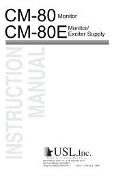
4. For each channel a single trace connects pins 2 <strong>and</strong> 6 together on the output relay of the channel (see figure 1, typical). Locate<br />
<strong>and</strong> mark each trace so that it is easy to find by inspection.<br />
RV0001 1
5. De-solder <strong>and</strong> remove the output relays from channels 1,6 <strong>and</strong> 11. The trace that connects pins 2 <strong>and</strong> 6 on these channels is<br />
located on the top side of the circuit board under the relays. Removal of the relays on channels 1,6 <strong>and</strong> 11 will expose the trace<br />
so that it can be cut.<br />
Note: Take care when removing the relays so as not to damage them or the circuit board. The use of a vacuum de-soldering station<br />
is highly reccomended.<br />
6. Cut the traces that were marked in step 4. Be careful not to cut too deeply, because the circuit board is multi-layered <strong>and</strong><br />
damaged traces in the middle layers of the PCB cannot be repaired.<br />
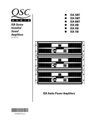
7. Solder a 1/8th watt, 5%, 100k ohm resistor on the bottom of the circuit board between pin 6 of the relay <strong>and</strong> the 100k ohm<br />
resistor connected to pin 2 of the relay (see figure 2, typical).<br />
Note: Be careful not to short the new component to any nearby traces or other components. Also note that the resistors for<br />
channels 1,6 <strong>and</strong> 11 can be placed in the same way as the other channels. It is only the location of the trace that is different.<br />
8. When all of the new components have been attached to the circuit board use a multimeter to measure between the positive <strong>and</strong><br />
negative audio terminals of each channel. The measurement should be 200k ohms indicating that each leg has an independent<br />
path to ground through its own 100k ohm resistor.<br />
9. Measure between the ground <strong>and</strong> the positive terminal of each channel. This measurement should be 100k ohms.<br />
10. Measure between the ground <strong>and</strong> the negative terminal of each channel. This measurement should be 100k ohms.<br />
Figure 1. Typical trace location<br />
Figure 2. Typical resistor placement<br />
11. If all of the measurements are correct then the PCB can be reinstalled into the chassis. Note the orientation of the new components<br />
<strong>and</strong> be careful not to snag them or short circuit them on any of the mounting hardware in the chassis.<br />
12. Repeat the meaurements taken in steps 8 through 11.<br />
13. Connect the RAVE units to a RAVE network <strong>and</strong> use a RAVE input unit to put audio onto the network. The audio can then be<br />
picked up at the Master/Slave RAVE pair for testing purposes.<br />
2 RV0001
13. With the audio outputs of two RAVE 160’s (or 188’s) tied together <strong>and</strong> the BNC cable between the SYNC out <strong>and</strong> Slave in of the<br />
RAVE units, the audio signal should be clean <strong>and</strong> distortion free just as with a single unit by itself. This can be verified with the<br />
Audio Precision System 1 <strong>and</strong>/or with the oscilloscope.<br />
14. Make sure there are no foreign objects in the RAVE. Re-install the top covers <strong>and</strong> return the units to service.<br />
Contact information<br />
If you need any further information regarding this service procedure, please contact QSC Technical <strong>Service</strong>s at the addresses or<br />
numbers below. You can also order RAVE parts; to expedite processing please use the correct part number when ordering.<br />
Telephone: 1-800-772-2834 (within USA only)<br />
+1 714-957-7150<br />
Fax: +1 714-754-6173<br />
E-mail:<br />
tech_support@qscaudio.com<br />
Web Site: www.qscaudio.com (product info/support)<br />
www.qscstore.com (on-line accessory <strong>and</strong> replacement component sales)<br />
Postal <strong>and</strong> parcel address:<br />
QSC Audio Products, Inc.<br />
Technical <strong>Service</strong>s Group<br />
1665 MacArthur Blvd.<br />
Costa Mesa, CA 92626 USA<br />
RV0001 3