Traffic Signal Design - Section 11 Detectors - RTA
Traffic Signal Design - Section 11 Detectors - RTA
Traffic Signal Design - Section 11 Detectors - RTA

You also want an ePaper? Increase the reach of your titles
YUMPU automatically turns print PDFs into web optimized ePapers that Google loves.
<strong>Traffic</strong> signal design<br />
<strong>Section</strong> <strong>11</strong> - <strong>Detectors</strong>
The traffic signal design guidelines have been developed to assist in designing traffic control signals.<br />
The guidelines are to comprise 16 sections and 5 appendices. These are initially being released<br />
individually and in no specific order. The sections which are to be released are as follows:<br />
Part<br />
<strong>Section</strong> 1<br />
<strong>Section</strong> 2<br />
<strong>Section</strong> 3<br />
<strong>Section</strong> 4<br />
<strong>Section</strong> 5<br />
<strong>Section</strong> 6<br />
<strong>Section</strong> 7<br />
<strong>Section</strong> 8<br />
<strong>Section</strong> 9<br />
<strong>Section</strong> 10<br />
<strong>Section</strong> <strong>11</strong><br />
<strong>Section</strong> 12<br />
<strong>Section</strong> 13<br />
<strong>Section</strong> 14<br />
<strong>Section</strong> 15<br />
<strong>Section</strong> 16<br />
Appendix A<br />
Appendix B<br />
Appendix C<br />
Appendix D<br />
Appendix E<br />
Appendix F<br />
Appendix G<br />
Title<br />
Investigation<br />
Warrants<br />
<strong>Design</strong> Process<br />
Plan Requirements<br />
Geometry<br />
Pavement Marking<br />
Phasing and <strong>Signal</strong> Group Display Sequence<br />
Lanterns<br />
Posts<br />
Signs<br />
<strong>Detectors</strong><br />
Controller<br />
Provision for Future Facilities<br />
<strong>Signal</strong>ised Mid-block Marked Footcrossings<br />
Special Situations<br />
References<br />
<strong>Design</strong> Plan Checklist<br />
<strong>Traffic</strong> <strong>Signal</strong> Symbols<br />
Location and Function of Lanterns<br />
Location and Dimensions of Components<br />
Left Turn on Red<br />
Level Crossing Interface – Concept of Operations<br />
Level Crossing Interface – <strong>Traffic</strong> <strong>Signal</strong> <strong>Design</strong> Guidance<br />
To determine which sections are currently available go to:<br />
www.rta.nsw.gov.au/doingbusinesswithus/downloads/technicalmanuals/trafficsignaldesign_dl1.html<br />
The information contained in the various parts is intended to be used as a guide to good practice.<br />
Discretion and judgement should be exercised in the light of the many factors that may influence<br />
the design of traffic signals at any particular site. The guidelines make reference, where relevant, to<br />
current Australian Standards and are intended to supplement and otherwise assist in their<br />
interpretation and application.
<strong>Traffic</strong> <strong>Signal</strong> <strong>Design</strong><br />
<strong>Section</strong> <strong>11</strong><br />
DETECTORS<br />
Special Note:<br />
As of 17 January 20<strong>11</strong>, the <strong>RTA</strong> is adopting the Austroads Guides (Guide to <strong>Traffic</strong><br />
Management) and Australian Standards (AS 1742, 1743 & 2890) as its primary technical<br />
references.<br />
An <strong>RTA</strong> Supplement has been developed for each Part of the Guide to <strong>Traffic</strong><br />
Management and relevant Australian Standard. The Supplements document any<br />
mandatory <strong>RTA</strong> practice and any complementary guidelines which need to be<br />
considered.<br />
The <strong>RTA</strong> Supplements must be referred to prior to using any reference material.<br />
This <strong>RTA</strong> document is a complementary guideline. Therefore if any conflict arises, the<br />
<strong>RTA</strong> Supplements, the Austroads Guides and the Australian Standards are to prevail.<br />
The <strong>RTA</strong> Supplements are located on the <strong>RTA</strong> website at www.rta.nsw.gov.au<br />
Version 1.3<br />
UNCONTROLLED WHEN PRINTED
Roads and <strong>Traffic</strong> Authority<br />
www.rta.nsw.gov.au<br />
VERSION: 1.0<br />
ISSUED: February 2008<br />
AMENDMENTS: Refer to Amendment Record<br />
APPROVED BY:<br />
SIGNED<br />
Phil Margison<br />
General Manager<br />
<strong>Traffic</strong> Management<br />
SIGNED<br />
Steve Levett<br />
A/General Manager<br />
Safer Roads<br />
AUTHORISED FOR USE BY:<br />
SIGNED<br />
Michael Bushby<br />
Director<br />
Network Management<br />
© 2008 Roads and <strong>Traffic</strong> Authority NSW<br />
Extracts from these guidelines may be reproduced providing<br />
the subject is kept in context and the source is acknowledged.<br />
Every effort has been made to supply complete and accurate<br />
information. However <strong>RTA</strong>, NSW assumes no responsibility for its use.<br />
All trade name references herein are either trademarks or<br />
registered trademarks of their respective companies.<br />
For policy and technical enquiries regarding these guidelines please contact:<br />
<strong>Traffic</strong> Management Branch<br />
Email: technical_directions_publication@rta.nsw.gov.au<br />
To access electronic copies of these and other guidelines go to:<br />
www.rta.nsw.gov.au/doingbusinesswithus/downloads/technicalmanuals/technicalmanuals_dl1.html<br />
For the latest amendments (if any) to these guidelines go to:<br />
www.rta.nsw.gov.au/doingbusinesswithus/downloads/technicalmanuals/trafficsignaldesign_dl1.html<br />
ISBN 978-1-921242-95-3 (Electronic only)<br />
<strong>RTA</strong>/Pub. 08.092<br />
ii Version 1.3<br />
UNCONTROLLED WHEN PRINTED
<strong>Traffic</strong> <strong>Signal</strong> <strong>Design</strong> – <strong>Section</strong> <strong>11</strong> <strong>Detectors</strong><br />
Contents<br />
<strong>11</strong>.1 INTRODUCTION .........................................................................................................<strong>11</strong>-1<br />
<strong>11</strong>.2 TYPES AND USES OF DETECTORS...............................................................................<strong>11</strong>-1<br />
<strong>11</strong>.3 VEHICLE LOOP DETECTORS .......................................................................................<strong>11</strong>-2<br />
<strong>11</strong>.3.1 Characteristics................................................................................................................................. <strong>11</strong>-2<br />
<strong>11</strong>.3.2 Installation and location ................................................................................................................. <strong>11</strong>-2<br />
<strong>11</strong>.3.3 Modes of operation ........................................................................................................................ <strong>11</strong>-2<br />
<strong>11</strong>.3.4 Types of vehicle loop detectors................................................................................................... <strong>11</strong>-3<br />
<strong>11</strong>.3.4.1 General...................................................................................................................................... <strong>11</strong>-3<br />
<strong>11</strong>.3.4.2 Stop line .................................................................................................................................... <strong>11</strong>-3<br />
<strong>11</strong>.3.4.3 Queue........................................................................................................................................ <strong>11</strong>-4<br />
<strong>11</strong>.3.4.4 Advance..................................................................................................................................... <strong>11</strong>-4<br />
<strong>11</strong>.3.4.5 Violation.................................................................................................................................... <strong>11</strong>-4<br />
<strong>11</strong>.3.4.6 Counting ................................................................................................................................... <strong>11</strong>-5<br />
<strong>11</strong>.3.4.7 Bicycle loop detectors ........................................................................................................... <strong>11</strong>-5<br />
<strong>11</strong>.4 PEDESTRIAN PUSH-BUTTON DETECTORS .................................................................<strong>11</strong>-5<br />
<strong>11</strong>.4.1 General.............................................................................................................................................. <strong>11</strong>-5<br />
<strong>11</strong>.4.2 Audio-tactile pedestrian facilities................................................................................................. <strong>11</strong>-6<br />
<strong>11</strong>.4.3 Tactile only pedestrian facilities ................................................................................................... <strong>11</strong>-7<br />
<strong>11</strong>.4.4 Pedestrian facilities on medians.................................................................................................... <strong>11</strong>-7<br />
<strong>11</strong>.5 LABELLING OF DETECTORS........................................................................................<strong>11</strong>-8<br />
<strong>11</strong>.6 NUMBERING OF DETECTORS.....................................................................................<strong>11</strong>-8<br />
<strong>11</strong>.7 DETECTOR LOGIC......................................................................................................<strong>11</strong>-9<br />
<strong>11</strong>.7.1 General.............................................................................................................................................. <strong>11</strong>-9<br />
<strong>11</strong>.7.2 Independently-timed marked foot crossings...........................................................................<strong>11</strong>-10<br />
<strong>11</strong>.7.3 Advance push-button calls ..........................................................................................................<strong>11</strong>-<strong>11</strong><br />
Version 1.3<br />
UNCONTROLLED WHEN PRINTED<br />
iii
<strong>Traffic</strong> <strong>Signal</strong> <strong>Design</strong> – <strong>Section</strong> <strong>11</strong> <strong>Detectors</strong><br />
Amendment record<br />
Please note that the following updates have been made to this document.<br />
Amendment<br />
No<br />
Page Description Issued Approved<br />
By<br />
1 <strong>11</strong>-<strong>11</strong> Fig <strong>11</strong>.2 amended to reflect new August R O’Keefe<br />
marked foot crossing markings<br />
2008 Mgr Policies &<br />
Guidelines<br />
2 Various Drawings VD018 series updated to<br />
TS-TN series<br />
August<br />
2009<br />
R O’Keefe<br />
Mgr Policies &<br />
3 <strong>11</strong>-5 Amendment to <strong>Section</strong> <strong>11</strong>.3.4.7<br />
regarding on-road bicycle detectors<br />
August<br />
2012<br />
Guidelines<br />
R O’Keefe<br />
Mgr <strong>Traffic</strong><br />
Policies,<br />
Guidelines &<br />
Legislation<br />
iv Version 1.3<br />
UNCONTROLLED WHEN PRINTED
<strong>Traffic</strong> <strong>Signal</strong> <strong>Design</strong> – <strong>Section</strong> <strong>11</strong> <strong>Detectors</strong><br />
<strong>11</strong>.1 INTRODUCTION<br />
<strong>Detectors</strong> are used to register the presence and/or passage of vehicles and pedestrians.<br />
Demands are generated by the detection of vehicles, operation of pedestrian push buttons and<br />
other sensors, switches and devices. These demands allow the controller to determine the<br />
signal displays required, their initiation and duration.<br />
This section discusses the various types of vehicle and pedestrian detectors and their location,<br />
labelling and numbering. There are also brief comments on detector operation and detector<br />
logic, but full details of these topics may be found in <strong>Traffic</strong> <strong>Signal</strong> Operation and drawing No.<br />
TS-TN-020 respectively.<br />
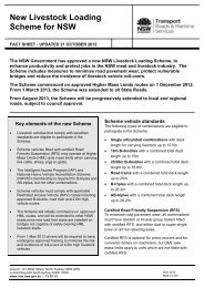
<strong>11</strong>.2 TYPES AND USES OF DETECTORS<br />
Figure <strong>11</strong>.1 shows the types of detectors currently in use:<br />
• vehicle detectors<br />
• push button detectors<br />
• special detectors<br />
The use of these detectors is determined by the type of traffic to be detected. This includes:<br />
• vehicles<br />
• pedestrians<br />
• priority traffic (e.g. emergency services vehicles and trains)<br />
• specific vehicles (e.g. buses, bicycles and wheelchairs)<br />
Figure <strong>11</strong>.1 Types of detectors<br />
Vehicle detectors are the most common. Many physical principles (such as radar, light and<br />
sound) have been used in vehicle detectors. The two types currently in use are the inductive<br />
loop detector and the microwave (radar) detector. The microwave detector cannot detect<br />
stationary vehicles and is only used as a temporary measure when loop detectors fail and is<br />
not further described here. Push-button detectors are usually provided for the use of<br />
pedestrians, however, in some instances they are also provided for either on-road or off-road<br />
bicycle riders.<br />
Version 1.3 <strong>11</strong>-1<br />
UNCONTROLLED WHEN PRINTED
<strong>Traffic</strong> <strong>Signal</strong> <strong>Design</strong> – <strong>Section</strong> <strong>11</strong> <strong>Detectors</strong><br />
<strong>11</strong>.3 VEHICLE LOOP DETECTORS<br />
<strong>11</strong>.3.1 Characteristics<br />
The inductive loop detector has proved to be the most reliable vehicle detector. This consists<br />
of two parts - a loop and a sensor unit. The loop consists of two to four turns of wire in a<br />
special pattern installed in saw slots up to 80 mm deep in the road surface. These loops are<br />
connected to the sensor units, which are normally located in the controller.<br />
The sensor units energise the loops with a high frequency signal from 20 kHz to100 kHz. This<br />
sets up an electromagnetic field in the vicinity of the loop. When a metallic object (such as a<br />
vehicle) passes over the loop, it causes a change in inductance. The sensor unit detects this<br />
and passes a signal to the controller's detector input. The principle is the same as that used in<br />
many metal detectors, i.e. when a metallic object enters an electromagnetic field, the field is<br />
disturbed.<br />
The detection area is approximately equal to the loop area. The loop area is less sensitive to<br />
some vehicles e.g. motorcycles or vehicles with a proportion of non-metal components. The<br />
sensor unit can be automatically self adjusting. As the sensitivity is increased vehicles outside<br />
the loop area (e.g. in adjacent lanes) are likely to be detected when they should not be<br />
detected. The more sensitive it is to vehicles the more sensitive the loop becomes to<br />
environmental factors such as temperature, rain and electromagnetic fields.<br />
<strong>11</strong>.3.2 Installation and location<br />
Generally detectors should be located as shown in Appendix D Location & Dimensions of<br />
Components. Installation methods for stop-line and advance loop detectors are shown on<br />
drawings No. VC005-17 and No. VC005-18, respectively.<br />
When locating detectors the following points should be considered in regard to installation:<br />
• does the pavement in the vicinity of the detector need resurfacing or reconstructing<br />
(loop wire is vulnerable to damage, but needs to be close to the road surface for<br />
optimum sensitivity)<br />
• loops cannot be installed over any bridges, culverts, stormwater drains or similar<br />
structures unless there is at least 80 mm of covering pavement<br />
• loops cannot be installed closer than 300 mm to any ferrous metal object such as a<br />
manhole cover or pipe<br />
• the distance between the loop and the sensor unit (normally located in the<br />
controller) is limited to about 300 metres.<br />
The location and/or size of any detector may be varied to suit special circumstances such as<br />
geometry, location of expansion joints or ferrous metal objects. In the latter case electrical<br />
officers should be consulted before determining the location and/or size of any detector.<br />
Stop-line detectors should not be located on the departure side of the stop line. Clearances<br />
shown in Appendix D Location & Dimensions of Components must not be reduced. Settingout<br />
details must be shown for any detector which is not located in accordance with minimum<br />
clearances to pavement marking and kerbs.<br />
<strong>11</strong>.3.3 Modes of operation<br />
The sensor units for vehicle loop detectors can be operated in one of two modes - passage<br />
mode or presence mode.<br />
<strong>11</strong>-2 Version 1.3<br />
UNCONTROLLED WHEN PRINTED
<strong>Traffic</strong> <strong>Signal</strong> <strong>Design</strong> – <strong>Section</strong> <strong>11</strong> <strong>Detectors</strong><br />
In passage mode, the sensor unit produces a single pulse when a vehicle enters the detection<br />
zone. This effectively detects only moving vehicles, regardless of their length or speed. The<br />
time between successive pulses is the headway time.<br />
In presence mode, the sensor unit produces a continuous output whenever a vehicle is in the<br />
detection zone. This effectively detects both moving and stationary vehicles. The duration of<br />
the output varies depending on the length and speed of the vehicle. The presence time is<br />
limited to between five and ten minutes.<br />
<strong>11</strong>.3.4 Types of vehicle loop detectors<br />
<strong>11</strong>.3.4.1 General<br />
There are several types of vehicle detectors:<br />
• stop-line<br />
• queue<br />
• advance<br />
• violation<br />
• counting<br />
Details of these are discussed in the following sub-sections.<br />
<strong>11</strong>.3.4.2 Stop line<br />
Stop line detectors are the most common type of vehicle loop detector and are so named<br />
because they are located at the stop line. They are always operated in presence mode.<br />
Stop line detectors can be 4.5 m or <strong>11</strong>.0 m long. They should be located as set out in<br />
Appendix D. In both cases, the approach edge of the detector loop is located 6.0 m before<br />
the stop line. The position may be varied up to 5.0 m from the stop line (except for nonlocked<br />
or presence timed detectors) to avoid utilities or to suit the geometry of the<br />
intersection providing the detector's functionality is maintained. Setting-out dimensions for<br />
any non-standard location should be shown on the design layout.<br />
The <strong>11</strong>m long detector is used at locations where a shared or exclusive right turn lane permits<br />
filtering and a right turn phase is also provided. In practice, the <strong>11</strong> m detector is divided into<br />
two 4.5 m loops designated "approach" and "departure" which act together in some conditions<br />
and separately in others.<br />
When vehicle actuated traffic signals are intended to always operate in isolated mode (i.e. not<br />
part of SCATS), they should have stop line detectors installed in all lanes on all approaches.<br />
For traffic signals operating under SCATS, some of the detectors will have a dual role, i.e.<br />
tactical (to determine the demand and/or duration of phases in the same way as isolated traffic<br />
signals) and strategic (to provide traffic information to the SCATS regional computer to enable<br />
calculation of cycle lengths, phase splits and offsets for system control). In an effort to avoid<br />
non-essential detection, detectors should not automatically be provided in every lane of every<br />
approach at every signalised SCATS intersection. It is difficult, at the design stage, to<br />
determine exactly which detectors will be required for strategic purposes. However,<br />
experience has shown that at very simple, minor sites, the detectors on the coordinated route<br />
generally are not used either tactically or strategically. Some savings in detector installation<br />
and maintenance are achieved by omitting detectors at such locations. In these cases the<br />
Version 1.3 <strong>11</strong>-3<br />
UNCONTROLLED WHEN PRINTED
<strong>Traffic</strong> <strong>Signal</strong> <strong>Design</strong> – <strong>Section</strong> <strong>11</strong> <strong>Detectors</strong><br />
decision to not install detectors should be made by the officer responsible for the SCATS<br />
operation. If there is any doubt the Manager Network Operations, Transport Management<br />
Centre, should be consulted. If it is decided not to install detectors, the controller personality<br />
must be designed to terminate the coordinated route on a maximum only (i.e. no gap or waste<br />
termination) similar to a pedestrian-actuated site. This is necessary in case the controller ever<br />
runs isolated in fallback mode.<br />
<strong>11</strong>.3.4.3 Queue<br />
Queue detectors are used in special circumstances to detect stationary traffic for queue<br />
detection and strategic purposes and must therefore operate in presence mode. The<br />
dimensions of queue detectors are the same as a standard 4.5 m long stop-line detector.<br />
Typical applications include detection of:<br />
• traffic blocking the middle of a major intersection<br />
• full or overflowing right-turn bays<br />
• queues on freeway offload ramps that are likely to overflow onto the freeway itself<br />
• queues on or near a railway level crossing adjacent to a signalised intersection<br />
<strong>11</strong>.3.4.4 Advance<br />
Advance detectors are so named because they are located in advance of the stop-line. They<br />
are only used to detect moving vehicles and are therefore operated in passage mode.<br />
Advance detectors should only be considered at sites where the approach speed is high and<br />
particularly if there is a large proportion of heavy vehicles. Where possible, they should be<br />
located to suit the stopping distance required for the 85th percentile approach speed and may<br />
be used in addition to the normal stop-line detectors.<br />
<strong>11</strong>.3.4.5 Violation<br />
Violation detectors are not to be installed at new sites, however, where they currently exist<br />
the following criteria explains the installation process and operation features.<br />
Violation detectors are installed in conjunction with a red signal violation camera and flash unit<br />
to enable red signal traffic violations to be detected. If a vehicle passes over one of the<br />
detectors while facing a red signal, the camera and flash unit are activated.<br />
The camera equipment can only accept a single red input. This normally comes from the full<br />
red, hence violation detectors should only be installed in lanes where all traffic is stopped by<br />
the full red. This includes exclusive through lanes and shared lanes where there is no left- or<br />
right-turn green arrow displayed in conjunction with the full red. Alternatively, selected<br />
detector inputs can be used for vehicles controlled by a specific red signal, but it cannot be<br />
used with left turn on red.<br />
The location and dimensions of violation detectors are shown on drawing No. VC005-30. As<br />
they are located 0.2 m past the stop-line and parallel to it, they cannot be used where an <strong>11</strong>m<br />
stop-line detector is installed. Installation details are shown on drawing No. VD002-38. Note<br />
that if the stop-line is located on an angle, then the shape of the detector is a parallelogram<br />
because of the fact that it must be parallel to the stop-line. This is the only type of detector<br />
where this is permitted. In order to avoid false actuations, no part of the loop should be any<br />
closer than 1.2 m to the trajectory of cross or turning traffic of another phase.<br />
<strong>11</strong>-4 Version 1.3<br />
UNCONTROLLED WHEN PRINTED
<strong>Traffic</strong> <strong>Signal</strong> <strong>Design</strong> – <strong>Section</strong> <strong>11</strong> <strong>Detectors</strong><br />
There is a limit of four detectors per camera. These should be labelled as "Violation<br />
<strong>Detectors</strong>" and numbered 1 to 4 from the kerbside lane. It is not necessary to provide lane<br />
identification, i.e. L, C, R, etc. The numbering of violation detectors is independent of the<br />
numbering of other detectors. However, the normal detector input for detector 16 is<br />
connected to the camera unit so that camera alarms (brought about by no film, camera faults,<br />
etc.) can be conveyed to the SCATS master. Therefore, detector 16 must not be used for<br />
normal detectors when a red signal violation camera is installed.<br />
<strong>11</strong>.3.4.6 Counting<br />
SCATS can be used to obtain approximate vehicle counts by recording the number of detector<br />
actuations from the detector inputs. To obtain a complete count, special counting detectors<br />
can be provided in any lanes in which detectors would not normally be provided - usually<br />
uncontrolled left-turn slip lanes. These detectors have no effect on the controller operation,<br />
but use the controller's detector inputs. They must be placed on a detector input in the range<br />
of 1 to 24 and are usually operated in passage mode<br />
.<br />
Counting detectors should be located in the same position as if a stop-line was provided, but<br />
clear of any vehicles that are not intended to be detected. Dimensions and installation details<br />
are the same as for the detectors used for permanent counting stations as shown on drawing<br />
Nos VC005-20 and VC005-27.<br />
A counting detector has no effect on controller operation, hence it does not have a detector<br />
label. Instead, the detector should be labelled "Counting Detector". If there is more than one<br />
at a particular site, each can be distinguished by simple numbering, 1, 2 etc. If there are two<br />
or more adjacent detectors, they are further identified with a lane label as described in <strong>Section</strong><br />
<strong>11</strong>.5.<br />
<strong>11</strong>.3.4.7 Bicycle loop detectors<br />
On-road bicycle detectors are different from the normal vehicle detectors in that they consist<br />
of 2 separate overlapping loops with each having 3 turns and laid in a figure 8 with separate<br />
sensor inputs to the controller (refer to drawings VC005-36 and VC005-38). The overall<br />
width of the double detector can vary up to 1.5 m depending on the width of the bicycle lane<br />
and the need to allow a 0.2 m offset from the detector edge to the edge of the bicycle lane.<br />
Multiple bicycle detectors would be required when installing an expanded bicycle storage area,<br />
one double detector for each lane being provided.<br />
Off-road passage bicycle detectors are 1.1 m long and vary in width to allow a 0.1 m offset<br />
from the detector to the edge of the bicycle path. They are cut at a 45 degree angle to the<br />
path flow and laid in a figure 8 induction loop.<br />
All bicycle detectors should also be used for bicycle counting purposes.<br />
<strong>11</strong>.4 PEDESTRIAN PUSH-BUTTON DETECTORS<br />
<strong>11</strong>.4.1 General<br />
Pedestrian push-button detectors are used to register demands by pedestrians and in some<br />
cases either on-road or off-road cyclists. They should be provided on the posts on each<br />
approach to a marked foot crossing and on any median post adjacent to a marked foot<br />
crossing. The push-button should be mounted on the post 1m above ground level.<br />
Version 1.3 <strong>11</strong>-5<br />
UNCONTROLLED WHEN PRINTED
<strong>Traffic</strong> <strong>Signal</strong> <strong>Design</strong> – <strong>Section</strong> <strong>11</strong> <strong>Detectors</strong><br />
Kerbside push-buttons are generally oriented so that the face of the assembly is normal to the<br />
longitudinal axis of the marked foot crossing. A single, vertical arrow disc is fitted to such<br />
assemblies as shown on drawing Nos VD001-7 and VE530-8. This orientation is important to<br />
many visually impaired pedestrians who are taught to determine the crossing direction by<br />
feeling the face of the push-button housing, especially audio-tactile types. Any push-buttons<br />
which are not normal to the crossing can be confusing to visually impaired pedestrians. This<br />
unnecessarily complicates their use of the crossing and compromises safety. If the correct<br />
orientation cannot be achieved, the arrow disc must be adjusted to indicate the approximate<br />
direction of the crossing. The push-button symbol on the plan must be oriented accurately to<br />
show its orientation in the field.<br />
Where a median post is provided, the face of the push-button assembly is parallel to the<br />
marked foot crossing and fitted with a two-way arrow disc.<br />
Mounting two push-buttons on the one post should be avoided. However, where this is<br />
unavoidable each should be oriented such that a single horizontal arrow disc may be fitted<br />
pointing in the actual direction pedestrians are required to cross the road. Audio-tactile<br />
driver units must not be fitted to the post in this situation (see <strong>Section</strong> <strong>11</strong>.4.2).<br />
<strong>11</strong>.4.2 Audio-tactile pedestrian facilities<br />
Audio-tactile pedestrian facilities provide guidance to assist visually impaired pedestrians to<br />
cross safely at signalised marked foot crossings.<br />
The audible cue assists to locate the signal post and push-button and the change in pulse<br />
indicates the green ”walk” and the red “don’t walk” phases of the crossing. The audible cue<br />
also provides guidance to locate the opposite side of the crossing.<br />
The tactile cue provides additional assistance to the vision impaired pedestrian by indicating<br />
the crossing phase and the direction of the crossing.<br />
Audio-tactile facilities must be provided at all signalised marked foot crossings. This<br />
requirement is to comply with the Commonwealth Disability Discrimination Act, 1992, to<br />
ensure that pedestrian facilities at signalised marked foot crossings provide for all road users.<br />
Audio-tactile pedestrian facilities operate at noise levels as specified in <strong>RTA</strong> Specification<br />
ATS/4. They must not be turned off or reduced to a level such that they no longer meet the<br />
requirements of the vision impaired pedestrian.<br />
It must always be the intention of the designer to install full audio-tactile facilities whenever<br />
possible. However, there may be special circumstances, as detailed below, where this may not<br />
be desirable.<br />
Audio-tactile pedestrian facilities must not be installed at locations where their installation may<br />
not provide a clear unambiguous message to the vision impaired pedestrian. These locations<br />
are:<br />
• on a one stage crossing median post where it is not desirable to encourage a<br />
pedestrian to store on the median (see <strong>Section</strong> <strong>11</strong>.4.4)<br />
• where there are two independent push-buttons required on the same post #<br />
• where there are two independent push-buttons within 2 m of each other<br />
# If necessary, a short push-button post may be installed to separate two audio-tactile push<br />
buttons.<br />
<strong>11</strong>-6 Version 1.3<br />
UNCONTROLLED WHEN PRINTED
<strong>Traffic</strong> <strong>Signal</strong> <strong>Design</strong> – <strong>Section</strong> <strong>11</strong> <strong>Detectors</strong><br />
A note must be added to the plan to indicate which posts accommodate the audio-tactile<br />
push-buttons as the symbol alone is not strong enough to convey the message. For example:<br />
"Audio-tactile push-buttons are provided on Posts 1, 2, 5 and 6."<br />
If an audio-tactile push-button is installed on a short push-button post (i.e. Type 13 post), a<br />
note should be provided on the design layout to describe where the audio-tactile driver unit is<br />
located. For example:<br />
"The audio-tactile driver unit for the push-button on Post 9 is mounted on Post 8."<br />
<strong>11</strong>.4.3 Tactile only pedestrian facilities<br />
Where it is not suitable to provide audio-tactile pedestrian facilities as defined above,<br />
pedestrian push-buttons may be installed as tactile only, as a minimum treatment.<br />
If a tactile only push-button is installed then the correct symbol must be used and a note added<br />
to the plan indicating which push-button is tactile only.<br />
In circumstances where tactile only push-buttons are acceptable, they may be installed within<br />
the 2.0 m range.<br />
Notwithstanding the requirements above, tactile only push-buttons must not be used without<br />
discussion with peak organisations representing the vision impaired (such as Guide Dogs<br />
NSW/ACT or Vision Australia) and concurrence by the Manager Network Operations,<br />
Transport Management Centre.<br />
<strong>11</strong>.4.4 Pedestrian facilities on medians<br />
Where a median post is provided at a marked foot crossing, a pedestrian push-button must be<br />
provided, regardless of the median width. This is to enable a pedestrian the opportunity to<br />
call for a pedestrian phase if they were unable to complete their crossing in one stage (see<br />
<strong>Section</strong> 8.15 in Lanterns and <strong>Section</strong> 9.3 in Posts).<br />
A median, median post, pedestrian push-button and lanterns must be provided if a crossing is<br />
greater than 25 m in length.<br />
If a median width of 3.0 m or greater is available, a median post and pedestrian push-button<br />
must be provided, irrespective of the availability of an associated mast arm.<br />
The use of audio-tactile push-buttons on medians should be given careful consideration.<br />
Audio-tactile pedestrian facilities should be considered where it could reasonably be expected<br />
that vision impaired pedestrians will need to cross in two stages and a median of appropriate<br />
width is available for safe pedestrian storage. Hence, audio-tactile pedestrian facilities may be<br />
considered on straight crossings of 25 m or more and where a median of at least 2.0 m wide is<br />
available.<br />
It is also acceptable to use an audio-tactile push-button on a median post in a staggered median<br />
crossing situation, where the crossing will be made in two stages (offset), where there is at<br />
least 2 m separation of the median posts and the pedestrian movements are controlled by<br />
median fencing to direct the vision impaired.<br />
Version 1.3 <strong>11</strong>-7<br />
UNCONTROLLED WHEN PRINTED
<strong>Traffic</strong> <strong>Signal</strong> <strong>Design</strong> – <strong>Section</strong> <strong>11</strong> <strong>Detectors</strong><br />
<strong>11</strong>.5 LABELLING OF DETECTORS<br />
<strong>Detectors</strong> are labelled to indicate which phases they call or extend. For example, a detector<br />
that calls A phase and extends A and B phases is called an A-B detector.<br />
Where necessary to distinguish the approach or where detector functions differ within the<br />
same approach, a numerical suffix is added to the phase symbol (e.g. A-B1 and A-B2, C1 and<br />
C2). This should be shown without any intervening spaces and should not be superscripted or<br />
subscripted. The order of allocation of the numerical suffixes is in a clockwise direction from<br />
the V1 primary lantern.<br />
When advance detectors and stop-line detectors are provided on the same approach, the<br />
numerical suffix is added to the advance detectors before the stop-line detectors.<br />
A group of adjacent detectors on the same approach may have the same call and extend<br />
functions and hence have the same label. When this occurs, an identifying lane label is added<br />
to distinguish the detectors. The lane label is based on the position of the detector in relation<br />
to the others when facing in the direction of travel. The label is selected from L, CL, C, CR<br />
and R (for left, centre left, centre, centre right and right respectively) as follows:<br />
• 2 lanes are L and R<br />
• 3 lanes are L, C and R<br />
• 4 lanes are L, CL, CR and R<br />
• 5 lanes are L, CL, C, CR and R<br />
Lane labelling is completely independent of the location of the kerb. Thus, a left detector is<br />
the left-most detector in a particular group, and not necessarily the one in the kerbside lane.<br />
<strong>11</strong>.6 NUMBERING OF DETECTORS<br />
<strong>Traffic</strong> signal controllers have detector inputs which are numbered. All detectors (including<br />
push-button detectors) on the design layout are numbered to indicate these inputs. This<br />
numbering is required in addition to the labelling described above. Table <strong>11</strong>.1 shows an<br />
example of detector numbering.<br />
Table <strong>11</strong>.1<br />
EXAMPLE OF DETECTOR NUMBERING<br />
Detector Label Detector Number<br />
A Left 1<br />
A Centre 2<br />
A Right 3<br />
A-B1 Departure 4<br />
A-B1 Approach 5<br />
A-B2 Left 6<br />
A-B2 Right 7<br />
B-C 8<br />
C1 9<br />
C2 Left 10<br />
C2 Right <strong>11</strong><br />
A Push-Buttons 12<br />
A-B Push-Buttons 13<br />
C Push-Buttons 14<br />
<strong>11</strong>-8 Version 1.3<br />
UNCONTROLLED WHEN PRINTED
<strong>Traffic</strong> <strong>Signal</strong> <strong>Design</strong> – <strong>Section</strong> <strong>11</strong> <strong>Detectors</strong><br />
In general, the numbers are allocated in ascending order based strictly on the alphanumeric<br />
sequence of the detector labels. If there is more than one detector with the same label, the<br />
detector numbers are ordered according to the lane label (i.e. L, CL, C, CR, R) before<br />
progressing to the next detector label. For <strong>11</strong> m detectors, the departure section is<br />
numbered before the approach section.<br />
The numbering of special counting detectors comes after normal vehicle detectors. As these<br />
detectors must be visible to SCATS, they must be numbered somewhere in the range 1 to 24.<br />
If there are 24 vehicle detectors in use for traffic signal control, then counting detectors<br />
cannot be used unless minor vehicle detectors are moved to detector numbers greater than<br />
24 or the detectors are paralleled, e.g. the L, C and R detectors are placed on the same input.<br />
If there is an emergency service phase, the last detector number after any push button<br />
detectors should be allocated to call this phase. If a second (separate) detector is used to call<br />
this phase or to call a second phase, then the next detector number should be allocated to the<br />
second detector. See drawing No. TS-TN-022 for further details.<br />
In SCATS, only detectors 1 to 24 are available for strategic purposes as vehicle detectors.<br />
Where there are more than 24 vehicle detectors, those detectors that are required for<br />
strategic purposes are to be numbered in the range 1 to 24 regardless of the alphanumeric<br />
detector labelling.<br />
Where sister linking is required, detector number 8 is to be allocated to the repeat detector<br />
from the linked site.<br />
Push-button detectors generally follow vehicle detectors. There is a maximum of 8 push<br />
button detector inputs in SCATS and these can be numbered up to, and including, number 32.<br />
For sites using the post mounted controller, detectors 1 to 12 are for vehicle detectors and<br />
the push button detectors follow the vehicle detectors, with a maximum of 8 push button<br />
detector inputs in SCATS, and these can be numbered up to, and including, detector number<br />
20.<br />
The numbering for vehicle detectors is placed within the detector symbol on the plan. Pushbutton<br />
detector numbers are added in brackets following each push-button detector label, e.g.<br />
A(12), A-B(13) and C(14). Note that push-buttons with the same detector label are to have<br />
the same detector number, unless the push buttons are required to be split, to suit the red<br />
arrow protection for a long pedestrian crossing.<br />
Detector numbers are not usually allocated to future detectors. It should only be considered<br />
in the case where the addition of a future detector does not warrant a change in the<br />
controller's personality, e.g. the addition of a lane due to imminent road widening or sealing.<br />
The reserved detector number should be shown on the design layout together with a suitable<br />
note requesting provision in the cabling and detector sensors for the reserved detector (see<br />
also <strong>Section</strong> 13 Provision for Future Facilities ).<br />
<strong>11</strong>.7 DETECTOR LOGIC<br />
<strong>11</strong>.7.1 General<br />
Vehicles can be detected during two parts of the traffic signal cycle. <strong>Traffic</strong> waiting for a green<br />
signal registers an initial demand that it requires right-of-way (i.e. calls a phase) and traffic<br />
already given the right-of-way via a green signal registers its continuing requirement for right-<br />
Version 1.3 <strong>11</strong>-9<br />
UNCONTROLLED WHEN PRINTED
<strong>Traffic</strong> <strong>Signal</strong> <strong>Design</strong> – <strong>Section</strong> <strong>11</strong> <strong>Detectors</strong><br />
of-way so that the green signal can be extended depending on the prevailing traffic conditions<br />
(i.e. extends a phase).<br />
Detector logic is used to specify the conditions under which an actuation from a detector can<br />
call or extend a phase. For example, the standard detector logic for a stop-line detector is:<br />
• demand a phase except while it is green<br />
• extend a phase while it is green<br />
In the above logic, there is only one phase involved and only one condition for each function.<br />
This amount of logic is sufficient for a simple two-phase design, but for most other types of<br />
phasing, several conditions may be required and a detector may demand and/or extend more<br />
than one phase. When designing detector logic for these situations, the basic aim is to<br />
minimise the cycle time while satisfying all the traffic and safety needs of the intersection. This<br />
is achieved by:<br />
• avoiding the introduction of unnecessary phases by only registering and maintaining<br />
demands which are actually required<br />
• demanding a phase that satisfies the most (or main) vehicle movements<br />
• minimising the variable initial green time by only allowing detectors to increment<br />
when a queue is forming<br />
• avoiding unnecessary extension of a phase, e.g. by ceasing extension by vehicles on a<br />
given movement when that movement also runs in the following phase<br />
The detector logic should be designed to operate in conjunction with SCATS regardless of<br />
whether or not SCATS is in use. Most importantly, the logic should attempt to provide the<br />
most efficient operation regardless of the phase sequence. Detector logic may require<br />
complex operation and it is imperative that the detector logic is expressed correctly in the<br />
manner described in drawing No. TS-TN-020. This facilitates the preparation of the controller<br />
personality.<br />
A detector specification schedule must be included on all design plans except for two-phase<br />
designs and standard diamond overlaps (see TS-TN-026 and TS-TN-027).<br />
The principles of detector logic, standard detector functions, the symbolic method used to<br />
prepare a detector specification schedule and examples are provided in drawing No. TS-TN-<br />
020. This includes detector logic for the normal push-button calling functions.<br />
<strong>11</strong>.7.2 Independently-timed marked footcrossings<br />
Generally two parallel and functionally identical marked foot crossings operate independently<br />
of one another so that each displays a walk signal only when demanded. This allows for<br />
separate lamp monitoring of each crossing and avoids unnecessarily delaying vehicle<br />
movements e.g. when the crossings are different lengths or when pedestrian protection is<br />
provided.<br />
The push-button detectors are given a numeric suffix the same as the associated pedestrian<br />
lantern to identify them as being independent and each detector is given a separate entry in the<br />
detector specification schedule as shown in Table <strong>11</strong>.2.<br />
<strong>11</strong>-10 Version 1.3<br />
UNCONTROLLED WHEN PRINTED
<strong>Traffic</strong> <strong>Signal</strong> <strong>Design</strong> – <strong>Section</strong> <strong>11</strong> <strong>Detectors</strong><br />
Table <strong>11</strong>.2<br />
DETECTOR SPECIFICATION SCHEDULE FOR INDEPENDENTLY TIMED<br />
MARKED FOOTCROSSINGS<br />
FN A(PB) C(L)<br />
A1 ________ ________<br />
SG/PS A1(WALK) A.A1(WALK)<br />
PB<br />
_ _<br />
DS - B.C<br />
FN A(PB) C(L)<br />
A2 ________ ________<br />
SG/PS A2(WALK) A.A2(WALK)<br />
PB<br />
_ _<br />
DS - B.C<br />
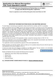
<strong>11</strong>.7.3 Advance push-button calls<br />
Where the pedestrian is required to cross a street in two separate movements such as the<br />
example in Figure <strong>11</strong>.2, an advance call for the second movement may be specified in order to<br />
provide progression across the whole street. This advance call is generally stored until the<br />
first walk is introduced as shown in the detector specification schedule in Table <strong>11</strong>.3.<br />
Figure <strong>11</strong>.2 Advance push-button call<br />
Where the left-turn movement is stopped, the A phase pedestrian movement is allowed to be<br />
introduced automatically.<br />
Version 1.3 <strong>11</strong>-<strong>11</strong><br />
UNCONTROLLED WHEN PRINTED
<strong>Traffic</strong> <strong>Signal</strong> <strong>Design</strong> – <strong>Section</strong> <strong>11</strong> <strong>Detectors</strong><br />
Table <strong>11</strong>.3<br />
DETECTOR SPECIFICATION SCHEDULE FOR ADVANCE<br />
PUSH-BUTTON CALLS<br />
FN A(PB).C(PB)* C(L)<br />
A-C _______ ______<br />
SG/PS A(WALK) A.A(WALK)<br />
PB<br />
_ _<br />
DS - B.C<br />
FN C(PB).A(PB)* A(L)<br />
C-A _______ _______<br />
PB<br />
SG/PS C(WALK) C.C(WALK)<br />
_ _<br />
DS - A.B<br />
* indicates that this call is stored until the<br />
WALK for the first PB demand is displayed<br />
NOTE:<br />
If there are three controlled crossings to a corner island, advance push-button calls<br />
are inappropriate as there is no way of knowing which pedestrian movement is<br />
required. In this case, the control of pedestrian movements across the left-turn<br />
slip lane may operate in accordance with one of the techniques described in TS-<br />
TN-021. If the traffic in the left-turn slip lane has an exclusive departure lane, then<br />
there is no "best" phase during which to stop the left turn. In this case, the slip<br />
lane may be controlled by an independently operated pedestrian movement.<br />
<strong>11</strong>-12 Version 1.3<br />
UNCONTROLLED WHEN PRINTED
[Inside rear cover<br />
– provided for double sided printing purposes only]
For further enquiries<br />
www.rta.nsw.gov.au<br />
13 22 13<br />
Roads and <strong>Traffic</strong> Authority<br />
March 2008<br />
<strong>RTA</strong>/Pub. 08.092