AVX Tantalum Leaded Capacitors - RYSTON Electronics sro
AVX Tantalum Leaded Capacitors - RYSTON Electronics sro
AVX Tantalum Leaded Capacitors - RYSTON Electronics sro

Create successful ePaper yourself
Turn your PDF publications into a flip-book with our unique Google optimized e-Paper software.
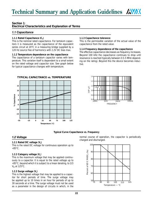
Technical Summary and Application Guidelines<br />
Section 1:<br />
Electrical Characteristics and Explanation of Terms<br />
1.1 Capacitance<br />
1.1.1 Rated Capacitance (C R )<br />
This is the nominal rated capacitance. For tantalum capacitors<br />
it is measured as the capacitance of the equivalent<br />
series circuit at 20°C in a measuring bridge supplied by a<br />
120 Hz source free of harmonics with 2.2V DC bias max.<br />
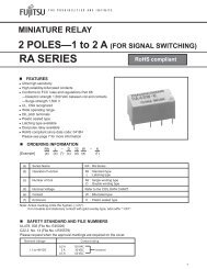
1.1.2 Temperature dependence on the capacitance<br />
The capacitance of a tantalum capacitor varies with temperature.<br />
This variation itself is dependent to a small extent<br />
on the rated voltage and capacitor size. See graph below<br />
for typical capacitance changes with temperature.<br />
1.1.3 Capacitance tolerance<br />
This is the permissible variation of the actual value of the<br />
capacitance from the rated value.<br />
1.1.4 Frequency dependence of the capacitance<br />
The effective capacitance decreases as frequency increases.<br />
Beyond 100 kHz the capacitance continues to drop until<br />
resonance is reached (typically between 0.5-5 MHz depending<br />
on the rating). Beyond this the device becomes inductive.<br />
TYPICAL CAPACITANCE vs. TEMPERATURE<br />
1.4<br />
1.2<br />
15<br />
10<br />
CAP (F)<br />
1.0<br />
0.8<br />
1.0F 35V<br />
% Capacitance<br />
5<br />
0<br />
-5<br />
0.6<br />
0.4<br />
100Hz 1kHz 10kHz 100kHz<br />
FREQUENCY<br />
-10<br />
-15<br />
-55 -25 0 25 50 75 100 125<br />
Temperature (°C)<br />
Typical Curve Capacitance vs. Frequency<br />
1.2 Voltage<br />
normal course of operation, the capacitor is periodically<br />
charged and discharged.<br />
1.2.1 Rated DC voltage (V R )<br />
This is the rated DC voltage for continuous operation up to<br />
100<br />
+85°C.<br />
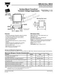
1.2.2 Category voltage (V C )<br />
This is the maximum voltage that may be applied continuously<br />
to a capacitor. It is equal to the rated voltage up to<br />
+85°C, beyond which it is subject to a linear derating, to 2/3<br />
V R at 125°C.<br />
1.2.3 Surge voltage (V S )<br />
This is the highest voltage that may be applied to a capacitor<br />
for short periods of time. The surge voltage may<br />
be applied up to 10 times in an hour for periods of up to<br />
30 seconds at a time. The surge voltage must not be used<br />
as a parameter in the design of circuits in which, in the<br />
22<br />
Percent of 85°C RVDC1 (VR)<br />
90<br />
80<br />
70<br />
60<br />
50<br />
75 85 95 105 115 125<br />
Temperature — °C