AVX Tantalum Leaded Capacitors - RYSTON Electronics sro
AVX Tantalum Leaded Capacitors - RYSTON Electronics sro
AVX Tantalum Leaded Capacitors - RYSTON Electronics sro

Create successful ePaper yourself
Turn your PDF publications into a flip-book with our unique Google optimized e-Paper software.
Technical Summary and Application Guidelines<br />
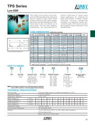
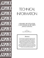
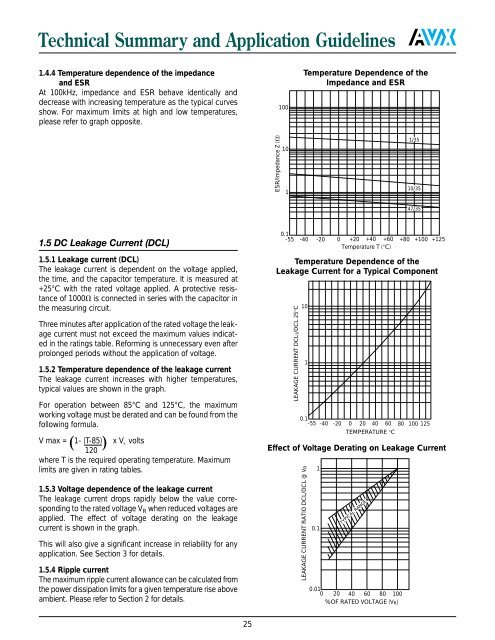
1.4.4 Temperature dependence of the impedance<br />
and ESR<br />
At 100kHz, impedance and ESR behave identically and<br />
decrease with increasing temperature as the typical curves<br />
show. For maximum limits at high and low temperatures,<br />
please refer to graph opposite.<br />
100<br />
Temperature Dependence of the<br />
Impedance and ESR<br />
ESR/Impedance Z ()<br />
10<br />
1<br />
1/35<br />
10/35<br />
47/35<br />
1.5 DC Leakage Current (DCL)<br />
1.5.1 Leakage current (DCL)<br />
The leakage current is dependent on the voltage applied,<br />
the time, and the capacitor temperature. It is measured at<br />
+25°C with the rated voltage applied. A protective resistance<br />
of 1000 is connected in series with the capacitor in<br />
the measuring circuit.<br />
Three minutes after application of the rated voltage the leakage<br />
current must not exceed the maximum values indicated<br />
in the ratings table. Reforming is unnecessary even after<br />
prolonged periods without the application of voltage.<br />
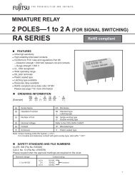
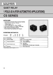
1.5.2 Temperature dependence of the leakage current<br />
The leakage current increases with higher temperatures,<br />
typical values are shown in the graph.<br />
For operation between 85°C and 125°C, the maximum<br />
working voltage must be derated and can be found from the<br />
following formula.<br />
V max =<br />
1- (T-85) x V volts<br />
R<br />
120<br />
where T is the required operating temperature. Maximum<br />
limits are given in rating tables.<br />
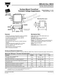
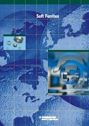
1.5.3 Voltage dependence of the leakage current<br />
The leakage current drops rapidly below the value corresponding<br />
to the rated voltage V R when reduced voltages are<br />
applied. The effect of voltage derating on the leakage<br />
current is shown in the graph.<br />
This will also give a significant increase in reliability for any<br />
application. See Section 3 for details.<br />
1.5.4 Ripple current<br />
The maximum ripple current allowance can be calculated from<br />
the power dissipation limits for a given temperature rise above<br />
ambient. Please refer to Section 2 for details.<br />
0.1<br />
-55 -40 -20 0 +20 +40 +60 +80 +100 +125<br />
Temperature T (°C)<br />
Temperature Dependence of the<br />
Leakage Current for a Typical Component<br />
LEAKAGE CURRENT DCLT/DCL 25°C<br />
10<br />
1<br />
0.1<br />
-55 -40 -20 0 20 40 60 80 100 125<br />
TEMPERATURE °C<br />
Effect of Voltage Derating on Leakage Current<br />
LEAKAGE CURRENT RATIO DCL/DCL @ VR<br />
1<br />
0.1<br />
TYPICAL RANGE<br />
0.01<br />
0 20 40 60 80 100<br />
%OF RATED VOLTAGE (V R)<br />
25