AVX Tantalum Leaded Capacitors - RYSTON Electronics sro
AVX Tantalum Leaded Capacitors - RYSTON Electronics sro
AVX Tantalum Leaded Capacitors - RYSTON Electronics sro

Create successful ePaper yourself
Turn your PDF publications into a flip-book with our unique Google optimized e-Paper software.
Technical Summary and Application Guidelines<br />
Section 3:<br />
Reliability and Calculation of Failure Rate<br />
3.1 Steady-State<br />
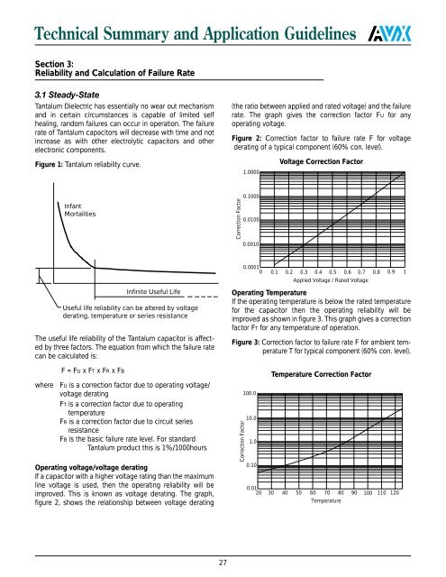
<strong>Tantalum</strong> Dielectric has essentially no wear out mechanism<br />
and in certain circumstances is capable of limited self<br />
healing, random failures can occur in operation. The failure<br />
rate of <strong>Tantalum</strong> capacitors will decrease with time and not<br />
increase as with other electrolytic capacitors and other<br />
electronic components.<br />
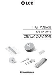
Figure 1: <strong>Tantalum</strong> reliability curve.<br />
(the ratio between applied and rated voltage) and the failure<br />
rate. The graph gives the correction factor FU for any<br />
operating voltage.<br />
Figure 2: Correction factor to failure rate F for voltage<br />
derating of a typical component (60% con. level).<br />
1.0000<br />
Voltage Correction Factor<br />
Infant<br />
Mortalities<br />
Correction Factor<br />
0.1000<br />
0.0100<br />
0.0010<br />
Infinite Useful Life<br />
Useful life reliability can be altered by voltage<br />
derating, temperature or series resistance<br />
The useful life reliability of the <strong>Tantalum</strong> capacitor is affected<br />
by three factors. The equation from which the failure rate<br />
can be calculated is:<br />
F = FU x FT x FR x FB<br />
where FU is a correction factor due to operating voltage/<br />
voltage derating<br />
FT is a correction factor due to operating<br />
temperature<br />
FR is a correction factor due to circuit series<br />
resistance<br />
FB is the basic failure rate level. For standard<br />
<strong>Tantalum</strong> product this is 1%/1000hours<br />
Operating voltage/voltage derating<br />
If a capacitor with a higher voltage rating than the maximum<br />
line voltage is used, then the operating reliability will be<br />
improved. This is known as voltage derating. The graph,<br />
figure 2, shows the relationship between voltage derating<br />
0.0001<br />
0 0.1 0.2 0.3 0.4 0.5 0.6 0.7 0.8 0.9 1 <br />
Applied Voltage / Rated Voltage<br />
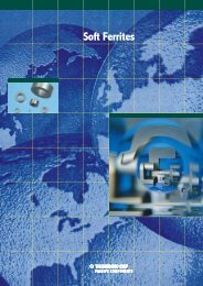
Operating Temperature<br />
If the operating temperature is below the rated temperature<br />
for the capacitor then the operating reliability will be<br />
improved as shown in figure 3. This graph gives a correction<br />
factor FT for any temperature of operation.<br />
Figure 3: Correction factor to failure rate F for ambient temperature<br />
T for typical component (60% con. level).<br />
Correction Factor<br />
100.0<br />
10.0<br />
1.0<br />
0.10<br />
Temperature Correction Factor<br />
0.01<br />
20 30 40 50 60 70 80 90 100 110 120<br />
Temperature<br />
27