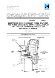
I_0316_M200S(B) finished.indd - Hofmann Megaplan
I_0316_M200S(B) finished.indd - Hofmann Megaplan
I_0316_M200S(B) finished.indd - Hofmann Megaplan

You also want an ePaper? Increase the reach of your titles
YUMPU automatically turns print PDFs into web optimized ePapers that Google loves.
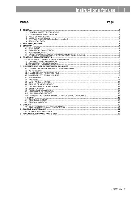
Instructions for use<br />
I<br />
INDEX<br />
Page<br />
1 - GENERAL .....................................................................................................................................................................3<br />
1.1 - GENERAL SAFETY REGULATIONS ...............................................................................................................3<br />
1.1.1 - STANDARD SAFETY DEVICES ....................................................................................................................3<br />
1.2 - FIELD OF APPLICATION .................................................................................................................................3<br />
1.3 - OVERALL DIMENSIONS (standard protection) ................................................................................................3<br />
1.4 - TECHNICAL DATA ...........................................................................................................................................4<br />
2 - HANDLING , HOISTING .............................................................................................................................................4<br />
3 - START-UP ....................................................................................................................................................................4<br />
3.1 - ANCHORING ....................................................................................................................................................4<br />
3.2 - ELECTRICAL CONNECTION ..........................................................................................................................4<br />
3.3 - ADAPTER MOUNTING ....................................................................................................................................5<br />
3.4 - WHEEL GUARD ASSEMBLY AND ADJUSTMENT (Exploded views) .............................................................5<br />
4 - CONTROLS AND COMPONENTS ...............................................................................................................................5<br />
4.1 - AUTOMATIC DISTANCE MEASURING GAUGE .............................................................................................5<br />
4.2 - CONTROL PANEL AND DISPLAY ...................................................................................................................6<br />
4.2.1 OPERATION FUNCTIONS MENU ....................................................................................................................7<br />
5 - INDICATION AND USE OF THE WHEEL BALANCER ..............................................................................................8<br />
5.1 - USE OF THE GAUGE INSTALLED IN THE MACHINE ....................................................................................8<br />
5.2 - AUTO SELECT ..................................................................................................................................................8<br />
5.2.1 - AUTO SELECT FOR STEEL RIMS .................................................................................................................8<br />
5.2.2 - AUTO SELECT FOR ALU M RIMS .................................................................................................................9<br />
5.3 - ALU 3M RIMS .................................................................................................................................................10<br />
5.4 - PAX RIMS .........................................................................................................................................................11<br />
5.5 - ALU 1 AND ALU 4 RIMS .................................................................................................................................12<br />
5.6 - RESULT OF MEASUREMENT .......................................................................................................................13<br />
5.7 - DOUBLE OPERATOR PROGRAM ..................................................................................................................13<br />
5.8 - SPLIT FUNCTION .........................................................................................................................................14<br />
5.9 - UNBALANCE OPTIMIZATION ........................................................................................................................15<br />
5.10 - ALU AND STATIC MODES.............................................................................................................................16<br />
5.11 - MINISTAT - AUTOMATIC MINIMIZATION OF STATIC UNBALANCE............................................................17<br />
6 - SET UP ..............................................................................................................................................................18<br />
6.1 - SELF-DIAGNOSTICS .....................................................................................................................................18<br />
6.2 - SELF-CALIBRATION ......................................................................................................................................19<br />
7 - ERRORS ....................................................................................................................................................................20<br />
7.1 - INCONSISTENT UNBALANCE READINGS ..................................................................................................21<br />
8 - ROUTINE MAINTENANCE .......................................................................................................................................22<br />
8.1 - TO REPLACE THE FUSES ............................................................................................................................22<br />
9 - RECOMMENDED SPARE PARTS LIST ...................................................................................................................22<br />
I <strong>0316</strong> GB - 1
I <strong>0316</strong> GB - 2
1 - GENERAL<br />
1.1 - GENERAL SAFETY REGULATIONS<br />
- The machine should only be used by authorized and suitably trained personnel.<br />
- Do not use the machine for purposes other than those specified in this manual.<br />
- The machine should not be modified in any way except for those modifications explicitly carried out by<br />
the manufacturer.<br />
- Never remove the safety devices. Any work on the machine should only be carried out by speciali<br />
personnel.<br />
- Avoid using strong jets of compressed air for cleaning.<br />
- Use alcohol to clean the plastic panel or shelves (AVOID LIQUIDS CONTAINING SOLVENTS).<br />
- Before starting the wheel balancing cycle, make sure that the wheel is securely locked on the adapter.<br />
- The machine operator should avoid wearing clothes with flapping edges.<br />
- Make sure that unauthorized personnel do not approach the machine during the work cycle.<br />
- Avoid placing objects inside the base as they could impair the correct operation of the machine.<br />
1.1.1 - STANDARD SAFETY DEVICES<br />
- Stop key that stops the motor when an emergency arises.<br />
- Highly shock resistant plastic guard whose shape and size are designed to avoid the danger of<br />
counterweights spinning off in any direction except downwards. (option)<br />
- A microswitch will not let the machine start up if the guard is not down and stops the motor whenever the<br />
guard is raised.<br />
1.2 - FIELD OF APPLICATION<br />
The machine is designed for balancing wheels of cars , light commercial vehicles or motorcycles,<br />
weighing less than 70 Kg. It can be operated in a temperature range of 0° to +45°C.<br />
The following functions are provided: ; AUTO SELECT; ALU-M; ALU 3M; PAX; SPLIT; Unbalance optimization;<br />
Double operator; Self diagnostics; Self calibration.<br />
1.3 - OVERALL DIMENSIONS (standard protection)<br />
1384<br />
1174<br />
1162<br />
1645<br />
I <strong>0316</strong> GB - 3
1.4 - TECHNICAL DATA<br />
Weight with guard (excluding adapter) ................................... ~ 84 Kg.<br />
Single-phase power supply ..................................................... 115 / 230 V 50/60 Hz<br />
Protection class.......................................................................IP 54<br />
Max.power consumption .........................................................0,8 KW<br />
Balancing speed...................................................................... 100 min-1<br />
Cycle time for average wheel (14 kg)...................................... 6-8 seconds<br />
Max.resolution of measurement .............................................. 1 gram<br />
Position resolution ................................................................... ± 1.4 °<br />
Average noise.......................................................................... < 70dB (A)<br />
Rim-machine distance............................................................. 0 - 250 (310 mm)<br />
Rim width setting range........................................................... 1.5” ÷ 20” or 40 ÷ 510 mm<br />
Diameter setting range ............................................................ 10” ÷ 26” or 265 ÷ 665 mm<br />
Total wheel diameter inside standard guard ........................... 870 mm<br />
Total wheel width inside standard guard ................................. 430 mm<br />
2 - HANDLING, HOISTING<br />
NOTE: NEVER USE OTHER POINTS TO HOIST THE MACHINE<br />
3 - START - UP<br />
3.1 - ANCHORING<br />
The machine can only be operated on a flat non resilient floor. Make sure that the machine rests on the 3<br />
mounting points provided (see above) N.B.: It is advisable to secure the system to the ground using the<br />
specific feet (see above) in the event of continual use with wheels weighing over 35 Kg.<br />
3.2 - ELECTRICAL CONNECTION<br />
The machine is supplied with an electrical cable plus earth (ground).<br />
The supply voltage (and mains frequency) is given on the machine nameplate. It cannot be changed.<br />
Connection to mains should always be made by expert personnel.<br />
The machine should not be started up without proper earthing.<br />
Connection to the mains should be through a slow acting safety swich rated at 3 A (230V) or 8 A (115V).<br />
I <strong>0316</strong> GB - 4
3.3 - ADAPTER MOUNTING<br />
The wheel balancer is supplied complete with cone<br />
type adapter for fastening wheels with central bore.<br />
Other optional adapters can be mounted:<br />
a) Remove threaded end piece A after backing off<br />
screw B.<br />
b) Mount the new adapter (see enclosed brochures).<br />
3.4 - WHEEL GUARD ASSEMBLY AND ADJUSTMENT (Exploded views)<br />
a) Insert the wheel guard tube in its seat.<br />
b) Fit the mounting bolts and tighten them securely.<br />
The guard closed position can be adjusted by means of relative screw accessible from the rear of the<br />
machine. Adjust the angular position of microswitch control.<br />
Correct position is the one which keeps the tube exactly horizontal with the wheel guard closed.<br />
4 - CONTROLS AND COMPONENTS<br />
4.1 - AUTOMATIC DISTANCE MEASURING GAUGE<br />
Allows measuring the distance of the point of application of the counterweight from the machine.<br />
I <strong>0316</strong> GB - 5
4.2 - CONTROL PANEL AND DISPLAY<br />
<br />
<br />
<br />
<br />
<br />
<br />
<br />
<br />
<br />
<br />
<br />
<br />
<br />
<br />
1-2 Digital readouts, AMOUNT OF UNBALANCE, inside/outside<br />
3-4 Digital readouts, POSITION OF UNBALANCE, inside/outside<br />
5 Indicators, correction mode selected<br />
6 Indicators, selection made<br />
7 Push button, unbalance reading < 5 g (25 oz)<br />
8 Push button, operator selection<br />
9 Push button, selection of mode of correction<br />
10 Push button, SPLIT (unbalance spread)<br />
11 Push button, FUNCTIONS MENU<br />
12 Push button, menu selection confirmation<br />
13 Push button, cycle start<br />
14 Push button, emergency/home<br />
15 Push button AUTO SELECT<br />
16 Push buttons, manual DIAMETER setting<br />
17 Push buttons, manual WIDTH setting<br />
18 Push button, unbalance optimization<br />
Note:<br />
- Only use the fingers to press the push buttons. Never use the counterweight pincers or<br />
other pointed objects.<br />
- In case of audible alarm connected (see par. OPERATION FUNCTIONS MENU), any push button<br />
operation sounds with a “beep” alarm.<br />
I <strong>0316</strong> GB - 6
4.2.1 - OPERATION FUNCTIONS MENU<br />
MENU'<br />
ENTER<br />
on/off audible<br />
alarm<br />
ENTER<br />
CONFIRM<br />
ENTER<br />
diameter<br />
mm/inch<br />
ENTER<br />
CONFIRM<br />
ENTER<br />
width<br />
mm/inch<br />
ENTER<br />
CONFIRM<br />
ENTER<br />
guard<br />
on/of<br />
ENTER<br />
CONFIRM<br />
ENTER<br />
start from<br />
guard closing<br />
ENTER<br />
CONFIRM<br />
ENTER<br />
approximates<br />
1-5g 0.1-25oz<br />
ENTER<br />
CONFIRM<br />
ENTER<br />
ENTER<br />
See SELF-DIAGNOSTICS<br />
ENTER<br />
See SELF-CALIBRATION<br />
ENTER<br />
g/oz<br />
unbalance<br />
unit<br />
ENTER<br />
CONFIRM<br />
ENTER<br />
DISTANCE automatic gauge calibration<br />
HOME<br />
STOP<br />
RETURN TO MEASUREMENT SCREEN<br />
I <strong>0316</strong> GB - 7
5 - INDICATION AND USE OF THE WHEEL BALANCER<br />
5.1 - USE OF THE GAUGE INSTALLED IN THE MACHINE<br />
For clip-on weights use the gauge in the upper position A.<br />
For adhesive weights use the gauge either in the upper<br />
position A or the lower position<br />
B. It is recomended to use Position B. As here one can see<br />
where the adhesive weights will be placed.<br />
POS A.<br />
Note: Always use the round part of the striker plate.<br />
POS B.<br />
5.2 - AUTO SELECT<br />
The machine automatically detects the right balancing program for steel and ALU M rims.<br />
5.2.1 - AUTO SELECT FOR STEEL RIMS<br />
Pull out the gauge to the edge of the rim. Keep it<br />
there until you hear a beep<br />
Push back the gauge to the resting position. The machine automatically has detected the mode for<br />
steel rims.<br />
Set the diameter indicated on the rim.<br />
Set the width indicated on the rim, or measure the<br />
width with the calliper (standard accessory).<br />
Make a measuring spin, turn the wheel to the right angles, fix the clip-on weights, and make a control<br />
spin.<br />
To balance more tyres of the same type and dimension the machine automatically stores the current<br />
wheel data.<br />
I <strong>0316</strong> GB - 8
5.2.2 - AUTO SELECT FOR ALU M RIMS<br />
FI<br />
FE<br />
Pull out the gauge to the left plane, where<br />
you want to fix an adhesive weight. Keep the<br />
gauge there until you hear a beep. Pull it<br />
further out to the right plane and wait for the<br />
second beep.<br />
The machine automatically has detected the<br />
ALU M mode.<br />
Push back the gauge to the resting position.<br />
Set the diameter indicated on the<br />
rim.<br />
Make a measuring spin<br />
For the adhesive weight on the left position turn the wheel to the correct angle and simply fix the weight<br />
by hand at the 12 o' clock position or use the gauge for repositioning as described below.<br />
For the adhesive weight on the right position turn the wheel to the correct angle.<br />
Pull out the gauge for repositioning and re-adjust the angle.<br />
Move the gauge further to the right<br />
until you hear a beep.<br />
Move the gauge further to the left until<br />
you hear a beep.<br />
Make a control spin<br />
To balance more tyres of the same type and dimension the machine automatically<br />
stores the current wheel data.<br />
To put in other dimensions or to change the balancing program press<br />
I <strong>0316</strong> GB - 9
5.3 - ALU 3M RIMS<br />
Press<br />
until the correct weight<br />
positions are indicated.<br />
To indicate the free choice of the position planes the ALU M LED is also lighting up at the same time.<br />
FI<br />
FE<br />
Pull out the gauge to the edge of the rim,<br />
where you want to fix the clip-on weight.<br />
Keep the gauge there until<br />
you hear a beep. Pull it further out to the<br />
right plane, where you want to fix the<br />
adhesive weight. Wait for the second beep.<br />
The machine confirms with ALU 3M<br />
Push back the gauge to the resting position.<br />
Set the diameter indicated on<br />
the rim.<br />
Make a measuring spin<br />
For the clip-on weight on the left position turn the wheel to the correct angle (see RESULT OF<br />
MEASUREMENT) and simply fix the weight by hand at the 12 o' clock position or use the gauge for<br />
repositioning as described below.<br />
For the adhesive weight on the right position turn the wheel to the correct angle.<br />
Pull out the gauge for repositioning and re-adjust the angle.<br />
Move the gauge further to the right<br />
until you hear a beep.<br />
Move the gauge further to the left until<br />
you hear a beep.<br />
Make a control spin<br />
To balance more tyres of the same type and dimension the machine automatically stores the current<br />
wheel data.<br />
To put in other dimensions or to change the balancing program press<br />
I <strong>0316</strong> GB - 10
5.4 - PAX RIMS<br />
Press<br />
FI<br />
FE<br />
Pull out the gauge to the left plane, where<br />
you want to fix an adhesive weight. Keep the<br />
gauge there until you hear a beep. Pull it<br />
further out to the right plane and wait for the<br />
second beep.<br />
The machine confirms with PAX<br />
Push back the gauge to the resting position.<br />
Set the diameter indicated on the rim in<br />
mm.<br />
Make a measuring spin<br />
For the adhesive weight on the left position turn the wheel to the correct angle (see RESULT OF<br />
MEASUREMENT) and simply fix the weight by hand at the 12 o' clock position or use the gauge for<br />
repositioning as described below.<br />
For the adhesive weight on the right position turn the wheel to the correct angle.<br />
Pull out the gauge for repositioning and re-adjust the angle.<br />
Move the gauge further to the right<br />
until you hear a beep.<br />
Move the gauge further to the left until<br />
you hear a beep.<br />
Make a control spin<br />
To balance more tyres of the same type and dimension the machine automatically stores the current<br />
wheel data.<br />
To put in other dimensions or to change the balancing program press<br />
I <strong>0316</strong> GB - 11
5.5 - ALU 1 AND ALU 2 RIMS<br />
Put in the wheel data as for steel rims described in AUTO SELECT FOR STEEL RIMS.<br />
Make the measuring spin.<br />
Press<br />
ALU<br />
as often as the LEDs for ALU 1 or ALU 2 are lighting up.<br />
Fix the weights at the indicated positions.<br />
Make a control spin.<br />
To balance more tyres of the same type and dimension the machine automatically stores the current<br />
wheel data.<br />
Note for ALU M/PAX programs:<br />
For the outer/right diameter the machine automatically calculates 80% of the value of the inner/left<br />
diameter.<br />
Note for ALU 3M programs:<br />
For the outer/right diameter the machine automatically calculates - 2" of the value of the inner/left<br />
diameter.<br />
For very special shaped rims you can adjust the right diameter as follows:<br />
Press one of the widths buttons for 3<br />
seconds.<br />
Adjust the right diameter to the shape<br />
of the rim.<br />
I <strong>0316</strong> GB - 12
5.6 - RESULT OF MEASUREMENT<br />
Inside correction<br />
Outside correction<br />
After performing a balancing spin, the amounts of unbalance are shown on the digital readouts.<br />
Digital readouts with LED ‘s 3 - 4 lit up indicate the correct angular wheel position to mount the counterweights<br />
(12 o’clock position). In case of audible alarm activated (see par. OPERATION FUNCTIONS MENU), the<br />
correction position will sound with a “beep” alarm. If the unbalance is less than the threshold selected, 0 is<br />
displayed instead of the unbalance; with FINE it is possible to read the values below the threshold chosen<br />
gram by gram.<br />
To enable automatic distance acquisition for a new wheel to be balanced, press<br />
N.B.:<br />
For wheel diameters less than or equal to 13” and at temperatures around 0°C, the wheel<br />
balancer automatically initiates a special measurement cycle involving two consecutive<br />
measurements. The precision of unbalance values and the reliability of the wheel balancer are<br />
unaffected. This type of operation is reset every time the wheel balancer is switched on.<br />
If the mobile symbol<br />
should appear at the end of any balancing start operation, turn<br />
the wheel by hand until the unbalance values are displayed.<br />
5.7 - DOUBLE OPERATOR PROGRAM<br />
This program allows memorizing the dimensions of two types of wheels. Thus two operators can work<br />
simultaneously on two differents cars using the same balancing machine. The system memorizes two<br />
programs with various preset dimensions.<br />
1 - Press USER to select operator (1 or 2). Selection is confirmed by panel-mounted Led.<br />
2 - Enter the dimensions (see AUTO SELECT ).<br />
3 - Press START to carry out the balancing as usual and to store the program.<br />
With<br />
USER<br />
program 1 or 2 is called for subsequent balancing operations without having to newly<br />
enter the dimensions.<br />
I <strong>0316</strong> GB - 13
5.8 - SPLIT FUNCTION (unbalance spread)<br />
The SPLIT function is used to position the adhesive weights behind the wheel spokes so that they are no<br />
longer visible. It is advisable to utilise this function only in the event of static unbalance or with<br />
ALU-M, ALU-3M or PAX functions. Input the wheel dimensions and start the spin. To start the SPLIT<br />
function, input the following data:<br />
Display example prior to<br />
SPLIT function<br />
Input the number of spokes (3-12)<br />
- Place any spoke in the vertical position.<br />
<br />
<br />
- Place the first Split unbalance in correction<br />
position 1.<br />
<br />
<br />
- Correction position 1<br />
<br />
<br />
- Place the second Split unbalance in correction<br />
position 2.<br />
<br />
<br />
- Correction position 2<br />
To return to normal unbalance display, press the button<br />
To perform a new spin, press the button START<br />
I <strong>0316</strong> GB - 14
5.9 - UNBALANCE OPTIMIZATION<br />
- This function serves to reduce the amount of weight to be added in order to balance the wheel<br />
- It is suitable for static unbalance exceeding 30g.<br />
- It improves the residual eccentricity of the tyre.<br />
A)<br />
- Mark with chalk a reference point on the adapter and rim<br />
- With the aid of a tyre remover, turn the rim on the tyre by<br />
180°<br />
- Refit the wheel with the reference mark coinciding between<br />
rim and adapter<br />
TYRE<br />
POSITION<br />
RIM POSITION<br />
- RH display: percentage reduction<br />
- LH display: actual static unbalance which can be reduced<br />
by rotation<br />
- Mark the two positions of the rim and tyre, and turn the rim<br />
on the tyre until the positions correspond in order to obtain<br />
the optimization on the display<br />
RETURN TO MEASUREMENT SCREEN<br />
If before pressing the button<br />
no spin was performed, the machine requires one, as follows:<br />
The procedure resumes from point A).<br />
I <strong>0316</strong> GB - 15
5.10 - ALU AND STATIC MODES<br />
On the control panel, press ALU or button to select the type required.<br />
The 5-LED display shows the position where to apply the weights. If a spin has already been performed,<br />
the processor automatically recalculates, for each change of mode, the amounts of unbalance according<br />
to the new calculation.<br />
Button → DYNAMIC → STATIC → DYNAMIC<br />
DYNAMIC<br />
Balancing of steel or rims with application of clipon<br />
weights on the rim edges.<br />
STATIC<br />
Button<br />
ALU<br />
The static mode is necessary for motorcycle<br />
wheels or when it is not possible to place the<br />
counterweights on both sides of the rim.<br />
→ ALU M → ALU 3M → ALU 1 → ALU 2 → ALU M<br />
ALU M<br />
Balancing of alloy rims with hidden application of<br />
adhesive weights.<br />
ALU 3M<br />
Combined application: clip-on weight inside and<br />
hidden adhesive weight on outside (Mercedes).<br />
ALU - 1<br />
Balancing of alloy rims with application of<br />
adhesive weights on the rim shoulders.<br />
ALU - 2<br />
Combined application: adhesive weight outside<br />
and clip-on weight inside.<br />
PAX<br />
PAX type wheel balancing<br />
I <strong>0316</strong> GB - 16
5.11 - MINISTAT - AUTOMATIC MINIMIZATION OF STATIC UNBALANCE<br />
Initial unbalance<br />
sx dx<br />
g g<br />
Position 50°<br />
Possible approximation<br />
sx<br />
g<br />
dx sx dx sx dx sx dx<br />
g<br />
g<br />
g<br />
4 g static residual 3 g 1 g 6 g<br />
static residual static residual static residual<br />
g<br />
g<br />
g<br />
g<br />
With a traditional<br />
balancing machine<br />
Choice with minimum<br />
static residual<br />
This program is designed to improve the quality of balancing without any mental effort or loss of time<br />
by the operator. In fact by using the normal commercially available weights, with pitch of 5 in every 5<br />
g, and by applying the two counterweights which a conventional wheel balancer rounds to the nearest<br />
value, there could be a residual static unbalance of up to 4 g. The damage of such approximation is<br />
emphasized by the fact that static unbalance is cause of most of disturbances on the vehicle. This new<br />
function automatically indicates the optimum entity of the weights to be applied by approximating them<br />
in an “intelligent” way according to their position in order to minimize residual static unbalance. If it is not<br />
possible to minimize completely the static unbalance keeping in tolerance the dynamic unbalance, this<br />
function has the solution to minimize the static unbalance.<br />
I <strong>0316</strong> GB - 17
6.1 - SELF-DIAGNOSTICS<br />
6 - SET UP<br />
ENTER<br />
DISPLAY TEST<br />
- All displays, readouts and LED’s should light up in sequence.<br />
- Turn the wheel in direction of rotation.<br />
- Turn the wheel in reverse direction of rotation.<br />
- In one complete rev.of the wheel (in direction of rotation) this should appear once<br />
ENTER<br />
- Test parameter (Values are not relevant)<br />
ENTER<br />
- Displays the DISTANCE sensor values<br />
ENTER<br />
END OF SELF-DIAGNOSTICS<br />
HOME<br />
STOP<br />
CANCEL SELF-DIAGNOSTICS IN ANY PHASE<br />
I <strong>0316</strong> GB - 18
6.2 - SELF-CALIBRATION<br />
For machine self-calibration proceed as follows:<br />
- Fit a medium-sized steel wheel on the shaft. Example: 6” x 14” (± 1”)<br />
- Preset the exact dimensions of the wheel mounted.<br />
CAUTION!!<br />
Presetting of incorrect dimensions would mean that the machine is not correctly<br />
calibrated, therefore all subsequent measurements will be incorrect until a new<br />
self-calibration is performed with the correct dimensions!!<br />
ENTER<br />
- Perform a spin under normal conditions.<br />
START<br />
- Add 100 g. (3.5 oz) on the outside in any position.<br />
START<br />
- Shift the 100 g.weight from the outside to the inside keeping the<br />
same position.<br />
START<br />
- Rotate the wheel so to have the 100 g. weight to the 12 o’clock<br />
position.<br />
ENTER<br />
END OF SELF-CALIBRATION<br />
HOME<br />
STOP<br />
CANCEL SELF-CALIBRATION IN ANY PHASE<br />
I <strong>0316</strong> GB - 19
7 - ERRORS<br />
During machine operation, various causes of faulty operation could occur. If detected by the microprocessor,<br />
they appear on the display as follows:<br />
ERROR<br />
Black<br />
MEANING<br />
The wheel balancer does not switch<br />
on.<br />
1. Verify correct connection to the mains.<br />
2. Check and if necessary replace the fuses on the power board.<br />
3. Verify display function in self-diagnostics mode.<br />
4. Replace the computer board.<br />
Err. 1 No rotation signal. 1. Verify belt tautness.<br />
2. Verify the function of the phase pick-up board and, in particular,<br />
the reset signal.<br />
3. Replace the phase pick-up board.<br />
4. Replace the computer board.<br />
Err. 2<br />
Speed too low during detection.<br />
During unbalance measurement<br />
rotation, wheel speed is less than 42<br />
rpm.<br />
1. Make sure that a car wheel is mounted on the wheel balancer.<br />
2. Verify belt tautness.<br />
3. Verify the function of the phase pick-up board and, in particular,<br />
the reset signal.<br />
4. Replace the computer board.<br />
Err. 3 Unbalance too high. 1. Verify wheel dimension settings.<br />
2. Check the connection of the piezo sensors.<br />
3. Perform machine calibration.<br />
4. Mount a wheel with more or less known unbalance (less than 100<br />
grammes) and verify machine result.<br />
5. Replace the computer board.<br />
Err. 4<br />
Err. 5<br />
Rotation in opposite direction.<br />
After pressing [START], the wheel<br />
begins to rotate in the opposite<br />
direction (anticlockwise).<br />
Guard open<br />
The [START] pushbutton was pressed<br />
without first closing the guard.<br />
1. Verify the connection of the UP/DOWN – RESET signals on the<br />
phase pick-up board.<br />
1. Reset the error by pressing pushbutton HOME/STOP.<br />
2. Close the guard.<br />
3. Verify the function of the protection Switch.<br />
4. Press the [START] pushbutton.<br />
Err. 7 / Err. 8 NOVRAM parameter read error 1. Repeat machine calibration<br />
2. Shut down the machine.<br />
3. Wait for a minimum time of ~ 1 Min.<br />
4. Re-start the machine and verify correct operation.<br />
5. Replace the computer board.<br />
Err. 9 NOVRAM parameter write error. Replace the computer board.<br />
Err. 11<br />
Speed too high error.<br />
During unbalance measurement<br />
rotation, wheel speed is more than<br />
270 rpm.<br />
1. Check if there is any damage or dirt on the timing disc.<br />
2. Verify the function of the phase pick-up board and, in particular,<br />
the reset signal.<br />
3. Replace the computer board.<br />
Err. 12 Unbalance measuring cycle error. 1. Verify phase pick-up board function.<br />
2. Verify correct motor operation.<br />
3. Verify belt tautness.<br />
4. Replace the computer board.<br />
Err.13/<br />
Err.14/<br />
Err.15/<br />
Err.16/<br />
Err.17/<br />
Err.18<br />
Unbalance measurement error. 1. Verify phase pick-up board function.<br />
2. Check the connection of the piezo sensors.<br />
3. Verify machine earth/ground connection.<br />
4. Mount a wheel with more or less known unbalance (less than 100<br />
grammes) and verify machine result.<br />
5. Replace the computer board.<br />
Procedure error in automatic distance<br />
acquisition in ALU M, ALU 3M and PX<br />
mode.<br />
1. Pull out the gauge and measure the outer side distance.<br />
2. Check distance gauge calibration.<br />
3. Check function of distance potentiometer.<br />
No unbalance value shown. 1. Turn the wheel until the imbalance is displayed<br />
I <strong>0316</strong> GB - 20
7.1 - INCONSISTENT UNBALANCE READINGS<br />
Sometimes after balancing a wheel and removing it from the balancing machine, it is found that, upon<br />
mounting it on the machine again, the wheel is not balanced.<br />
This does not depend on incorrect indication of the machine, but only on faulty mounting of the wheel on the<br />
adapter, i.e. in the two mountings the wheel has assumed a different position with respect to the balancing<br />
machine shaft centre line. If the wheel has been mounted on the adapter with screws, it could be possible<br />
that the screws have not been correctly tightened, i.e. crosswise one by one, or else (as often occurs) holes<br />
have been drilled on the wheel with too wide tolerances.<br />
Small errors, up to 10 grams (0.4 oz) are to be considered normal in wheels locked by a cone; the error is<br />
normally greater for wheels fastened with screws or studs.<br />
If, after balancing, the wheel is found to be still out-of-balance when refitted on the vehicle, this could be<br />
due to unbalance of the car brake drum or very often due to the holes for the screws on the rim and drum<br />
sometimes drilled with too wide tolerances.<br />
In such case a readjustment could be advisable using the balancing machine with the wheel mounted.<br />
I <strong>0316</strong> GB - 21
8 - ROUTINE MAINTENANCE<br />
Switch off the machine from the mains before carrying out any operation.<br />
8.1 - TO REPLACE THE FUSES<br />
Remove the weight holder shelf to gain access to the power supply board where the fuses are located<br />
(see Exploded Drawings). If fuses require replacement, use ones of the same current rating.<br />
If the fault persists, contact Technical Service Department.<br />
NONE OF THE OTHER MACHINE PARTS REQUIRE MAINTENANCE<br />
9 - RECOMMENDED SPARE PARTS LIST<br />
(For references, see exploded drawings)<br />
CODE<br />
DESCRIPTION<br />
020600503 Bearing 6005 - 2Z Ø 25/47/12<br />
181198630 Spring 19863P<br />
080077004 Rigid belt - Poly V - TB2 - 770 - 4 Vee’s<br />
67M38954H<br />
Position pick-up board with cable<br />
05PR55985<br />
LEXAN panel<br />
511242101 Oscillating switch 16A<br />
67M36950A<br />
Power board<br />
681002000 Fuses DM5x20 - 2A<br />
86SC58670<br />
Computerboard<br />
181206560 Spring, rim distance gauge 20656P<br />
86SB40113<br />
Cable with protective microswitch<br />
SPECIAL PARTS FOR 230 V MACHINE<br />
50FG54366<br />
Single phase motor 230V/50-60 Hz - 0.12Kw HB63B-4<br />
86SZ50867<br />
Complete power board<br />
611000312 Braking transformer 30 VA -0/50<br />
568001058 Capacitor 10MF 450V FASTON screw M8<br />
611000308 Power supply transformer 30 VA 230 9/9<br />
SPECIAL PARTS FOR 115 V MACHINE<br />
50FG54283<br />
Single phase motor 115V/50-60 Hz - 0.12Kw HB63B-4<br />
86SZ50868<br />
Complete power board<br />
611000313 Braking transformer 30 VA 115 -0/25<br />
568003558 Capacitor 35MF 450V FASTON screw M8<br />
611000307 Power supply transformer 30 VA 115-9/9<br />
I <strong>0316</strong> GB - 22