MARCH 2010 - International Flying Dutchman Class
MARCH 2010 - International Flying Dutchman Class
MARCH 2010 - International Flying Dutchman Class

You also want an ePaper? Increase the reach of your titles
YUMPU automatically turns print PDFs into web optimized ePapers that Google loves.
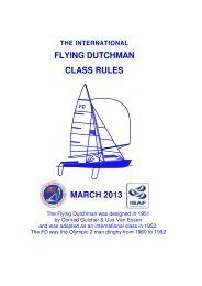
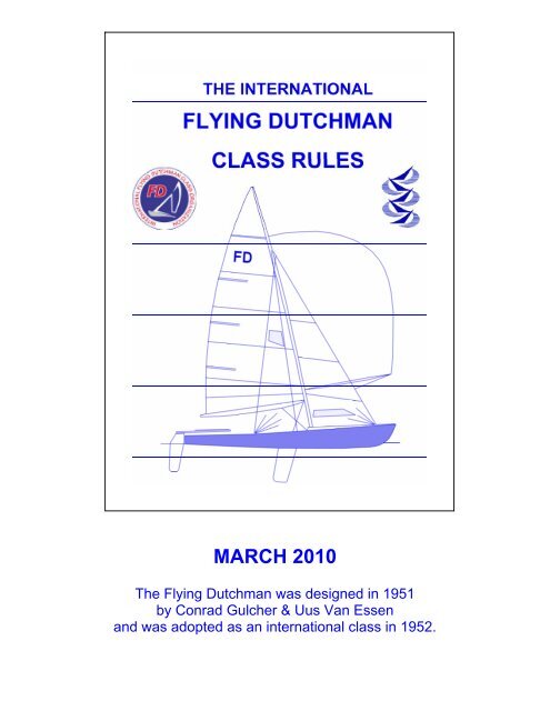
<strong>MARCH</strong> <strong>2010</strong><br />
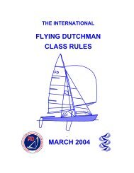
The <strong>Flying</strong> <strong>Dutchman</strong> was designed in 1951<br />
by Conrad Gulcher & Uus Van Essen<br />
and was adopted as an international class in 1952.
THE INTERNATIONAL FLYING DUTCHMAN<br />
CLASS RULES<br />
Version: FD-ISAF-3 Valid from 1 March <strong>2010</strong><br />
Rule<br />
Rule<br />
Number<br />
Number<br />
General 1-5 Centreboard 50<br />
Builders 6 Rudder 51<br />
<strong>International</strong> <strong>Class</strong> Fee / Sail Buttons 7 Spars and Rigging 57-67<br />
ISAF plaque 7-12.3 Mast 57-64<br />
Measurement Certificate & Form 8 Boom 65-66<br />
Owner's Responsibility/Subscription Sticker 9 Spinnaker pole 67<br />
Sail Numbers 10 Bands 68-71<br />
Measurers and Measurement Instructions 11 Fittings & Equipment 76-78<br />
Measurement Procedure 12 Sails 80-110<br />
Hull 20-43 Jib/Genoa 37-38, 92<br />
Construction and Shape 20-21 Mainsail 93-98<br />
Length overall 22 Battens 99-100<br />
Sections 23 Spinnaker 102-108<br />
Sheer 24 Crew 111<br />
Stem 25 Expensive Materials 112<br />
Transom 26-28 Equipment Limitations113<br />
Keel line measurements 29 Wet Clothing 114<br />
Keelbands 30 Outrigger 115<br />
Centreboard slot 31 Foot straps 116<br />
Deck 33 Shoes 117<br />
Section 9 Depth 34 Side Deck Pads 118<br />
Cockpit 35 Advertising 119<br />
Rubbing Strake 36 Sailing Instruction 120<br />
Jib/Genoa size 37-38 Propulsion 121<br />
Weight 39-43 Appendixes: Diagrams<br />
Buoyancy 44-47 Table of Offsets<br />
Trapeze 48-49
INTERNATIONAL FLYING DUTCHMAN CLASS RULES <strong>2010</strong> 3<br />
General<br />
1.0 ISAF Equipment and Racing Rules of Sailing<br />
These class rules are open class rules and shall be read in conjunction with the<br />
ISAF Equipment Rules of Sailing (ERS) and the Racing Rules of Sailing (RRS). The<br />
Measurement instructions, diagrams and the measurement plan form part of these<br />
rules. The object of these rules is to ensure that the boats of this class at all times<br />
conform, within the tolerances, in shape and weight of hull, centreboard, rudder<br />
and mast, and shape of sail-plan.<br />
Except where used in headings, when a term is printed in “bold” the definition in the<br />
ERS applies and when a term is printed in “bold italic” the definition in the RRS<br />
applies. Measurement instructions, within these rules, are in “italic” type.<br />
1.1 Certification Authority<br />
In alteration to ERS C.3.1 the Certification authority is the IFDCO, together with the<br />
ISAF.<br />
1.2 World and Continental Championships<br />
The IFDCO Championship Rules as set out in the IFDCO byelaws, Appendix I<br />
paragraph 9.4.1 states: The measurement committee will be appointed by the<br />
Organizing authority from names to be submitted to the IFDCO Championship<br />
Organizing Committee for approval. The IFDCO chief measurer shall be President of<br />
the measurement committee (Principal Event measurer).<br />
1.3 Interpretation of the <strong>Class</strong> Rules - General<br />
Interpretations of the class rules shall be made in accordance with the ISAF<br />
Regulations except as provided by 1.4<br />
1.4 Interpretation of the <strong>Class</strong> Rules – At an event<br />
Interpretations of the class rules at an event shall be carried out in accordance with<br />
the RRS and ERS, by the IFDCO chief measurer acting on behalf of the certification<br />
authority. The chief measurer must, as soon as practical after the event, inform the<br />
ISAF and the certification authority of any event interpretation.<br />
1.5 Axes of Measurement (ERS section H.3)<br />
The <strong>Flying</strong> <strong>Dutchman</strong> lines are specified by offsets in vertical and waterline planes.<br />
The DWL intersects the keel line at stations 0 and 10, thus the Hull Datum Point<br />
(HDP), which is at the intersection of the plane of the transom and the keel line is 11<br />
mm above the DWL. The planes of the measurement templates, which are<br />
determined by points measured along the keel line and sheerlines, are therefore<br />
only ideally at the station planes.
INTERNATIONAL FLYING DUTCHMAN CLASS RULES <strong>2010</strong> 4<br />
2. In order to achieve the objective in Rule 1, the General Committee of the IFDCO<br />
reserves the right to exclude a boat from racing even if it measures within the letter<br />
of these rules, if the owner or builder has taken advantage of a loophole in the rules<br />
in order to build a boat which is different in shape and/or weight of hull,<br />
centreboard, rudder, mast or sail plan, from the plans of the class.<br />
3. Alterations to the <strong>Class</strong> Rules shall be made in accordance with ISAF regulation<br />
26.11.<br />
4. In the event of disputes over interpretation, these rules take precedence over the<br />
plans. The English text will prevail. The words shall, must and will are mandatory.<br />
The word should is advisory and not mandatory. The words can and may are<br />
permissive.<br />
5. The IFDCO issues plans, measurement instructions, and measurement<br />
equipment, but can never be held liable for faults, errors, omissions, and deviations.<br />
6. Builders<br />
Yachts of the <strong>Flying</strong> <strong>Dutchman</strong> <strong>Class</strong> may be built by any yard that has paid the<br />
required annual fee and acquired a license from the ISAF Ltd. On request, and after<br />
advice from IFDCO, builders who do not build more than two <strong>Flying</strong> <strong>Dutchman</strong> a<br />
year shall receive a free license from the ISAF Ltd. Yards and amateurs building<br />
shells only do not need a license.<br />
7. <strong>International</strong> <strong>Class</strong> Fee (Royalty, Building Fee) Payable by Licensed Builders.<br />
7.1. The <strong>International</strong> <strong>Class</strong> Fee will be set by the ISAF in conjunction with IFDCO.<br />
Payment has to be directed to the ISAF Ltd. As receipt for the <strong>International</strong> <strong>Class</strong><br />
Fee payment, a numbered ISAF Plaque will be sent by the ISAF and must be glued<br />
to the boat before Fundamental measurement:<br />
a. To the starboard forward bulkhead (just forward of the mast), or if this is not<br />
possible:<br />
b. To the starboard aft side of the aft bulkhead of a half double bottom, or if this is<br />
not possible:<br />
c. To the starboard side of the hog (vertical inner keel) about 300 mm from the<br />
transom, or if this is not possible:<br />
d. To the aft bulkhead of the cockpit.<br />
7.2.Sail Buttons<br />
Each sail manufactured after 1 September 1984 shall have permanently fixed near<br />
to its tack an officially numbered IFDCO sail button. No sail will be accepted for<br />
measurement without an IFDCO sail button. Buttons must not be transferred from<br />
one sail to another. The sail makers must obtain buttons from the IFDCO.
INTERNATIONAL FLYING DUTCHMAN CLASS RULES <strong>2010</strong> 5<br />
8. Certificate and Measurement Form<br />
Measurement certificates are issued by the IFDCO after measurement by an<br />
IFDCO approved measurer, and receipt of the completed measurement forms.<br />
Measurement Forms: A certificate and sail number will be issued only upon the<br />
receipt by the IFDCO registration of 2 of the original 3 measurement forms, each<br />
signed by the builder and an IFDCO measurer, which show that the boat fully<br />
complies with all the rules. When the boat is measured outside the country of origin,<br />
it is desirable to have the signature of the builder, but not obligatory. When the boat<br />
proves to be within the rules, the 2 forms are to be signed by the IFDCO registration.<br />
One form is to be kept by the IFDCO Registration (white); one will go to the National<br />
Yachting Authority (green); or the National FD <strong>Class</strong> Association. The third copy<br />
(blue) may be kept by the measurer. A certified photocopy of the measurement form<br />
will be part of the certificate. The certificate together with the certified photocopy of<br />
the measurement form must be produced upon demand at official FD regattas.<br />
9. Owner's Responsibility<br />
No boat shall take part in <strong>Class</strong> Races unless it has:<br />
a. A valid certificate and certified copy of the measurement form with Sail number,<br />
and ISAF plaque number shown;<br />
b. Registration in the owner's name;<br />
c. A numbered ISAF plaque glued to the boat at the required place;<br />
d. The helmsman and crew have IFDC0 membership cards, with valid year<br />
stickers;<br />
e. A numbered IFDCO sail button on each sail;<br />
9.1 Annual Subscription Sticker<br />
A subscription sticker shall be sent by the National FD Secretary to every member<br />
who has paid his annual subscription, as a receipt. The National FD Secretary shall<br />
issue a membership card to each new member. The annual sticker shall be applied<br />
to this card as proof that the current subscription has been paid.<br />
9.2. It is the owner's responsibility that a boat racing is fully certified and conforms to<br />
these rules and the spirit of the class in all respects, and that after alterations or<br />
modifications, the boat is re-measured where applicable.<br />
Warning: In connection with this rule, which extends to major regattas also, owners<br />
are strongly advised to clear with the IFDC0 Committee any point that may<br />
contravene the spirit of the rules.<br />
9.3. The certificate of a second-hand boat is invalid until it has been put in the<br />
name of the new owner and countersigned by the IFDCO registration, which will<br />
issue a new sail number in the event of a country change.
INTERNATIONAL FLYING DUTCHMAN CLASS RULES <strong>2010</strong> 6<br />
10 Sail Numbers<br />
10.1. Sail numbers, preceded by the National Letters, shall be issued per country<br />
consecutively starting from 1.<br />
10.2. Personal Sail Numbers<br />
In accordance with ISAF RRS Appendix G1.1(c), National <strong>Class</strong> Associations may<br />
issue personal sail numbers (Sail numbers staying with the owner for every boat he<br />
owns as long as he sails FD) this number must be shown on the personal IFDCO<br />
Membership Card. After the sale of the boat, the new owner must use the original<br />
sail number or his own personal number on his sails.<br />
10.3. Hull numbers<br />
The sail number of the boat must be shown on the transom. The height of the letters<br />
must not be less than a minimum of 30 mm<br />
11 Measurers and Measurement Instructions<br />
11.1. Measurers must be approved by the IFDCO in close co-operation with their<br />
National Yachting Authority (MNA).<br />
11.2. A measurer shall not measure his own boat, a boat built by him or when he is<br />
in some way an interested party.<br />
11.3. Only the owner and crew of the boat, the measurer, measurer's assistants,<br />
members of the Jury and the IFDCO Technical Committee may be present during<br />
measurement at a major regatta.<br />
11.4. Hulls must be complete in every respect, and must have an ISAF plaque (Rule<br />
7.1) when presented for fundamental measurement. Sails, masts and other<br />
required gear may be measured separately.<br />
11.5. Partly built boats can be partly measured but the measurer must put under his<br />
signature - Partly measured - and must list on the measurement form the<br />
unmeasured items. The measurement form of such boats must also bear the name<br />
of the measurer who completed the measurement.<br />
11.6. If measurers find deviations which do not contravene the exact letter of the<br />
rules but which might contravene the spirit of the rules, they must, before signing the<br />
measurement form, submit the matter to the IFDCO Executive Committee.<br />
11.7. Only the IFDCO Executive committee can decide to give a waiver for a rule on<br />
which a boat deviates. The deviation and waiver are to be noted and countersigned<br />
by the IFDCO Chief measurer on the certificate and all 3 originals of the<br />
measurement form, before the certificate can be issued and become valid.<br />
12 Hull Measurement Procedure<br />
12.1. Boats shall be measured with official certified templates only.
INTERNATIONAL FLYING DUTCHMAN CLASS RULES <strong>2010</strong> 7<br />
12.2. The official templates will be issued by the IFDCO and the ISAF, and consist of<br />
6 Hull shape templates with tie bars, 1 Stem template, 1 Transom angle-height<br />
template and 1 Gunwale template. Each template must have the serial number of<br />
the set, must have been certified as correct and identified as such by a special mark<br />
made by the person appointed by IFDCO to check the templates.<br />
(numbers 13-19 are not used)<br />
Hull<br />
20. Deviations from the tolerances due to fair wear and damage, which do not affect<br />
the performance of the boat, shall not invalidate a certificate for a particular race,<br />
but shall be repaired, and put right as soon as possible.<br />
21. Within the tolerances allowed, the hull shape must conform to the Mylar plan of<br />
the sections, stem and transom at full size and the master plan of lines and verticals<br />
to be controlled by the table of offsets. The skin curvature radius must not be less<br />
than a minimum of 75 mm, except within 100 mm from the keelband. Hollows<br />
exceeding 1 mm in depth in the keel or in the hull surface aft of section 7, are not<br />
allowed. (For offsets and diagram see appendix)<br />
22. Overall hull length, measured along the deck line, is to be between 6044 mm<br />
and 6070 mm.<br />
23. Body sections: transom, 1, 3, 5, 7 and 9 must be verified with official numbered<br />
templates applied in the manner shown in the measurement plan.<br />
Tolerances: For the sections: transom, 1, 3, 5 and 7, the negative deviation must not<br />
exceed a maximum of 12.5 mm per section. For section 9, the positive deviation<br />
must not exceed a maximum of 12.5 mm. Boats built after 1 November 1981 have<br />
to conform to this rule.<br />
Instruction: See Measurement Plan. For sections transom, 1, 3, 5 and 7, the gap<br />
between template and hull must be between a maximum of 25 mm and a minimum<br />
of 12.5 mm. For section 9, the gap must be between a maximum of 12.5 mm and a<br />
minimum of 0 mm (i.e., templates touching the hull).<br />
24 Sheer height: The tolerance is plus 12 mm and minus 6 mm.<br />
Instruction: Measuring method<br />
a. After measuring the length, the hull is turned upside down and supported on<br />
trestles. The positions of the stations at the keel and the gunwale are to be<br />
determined by taking the following measurements from the outside of the transom<br />
along the keel and along the skin at the gunwale.<br />
Station 1 2 3 4 5 6 7 8 9<br />
Keel mark 732 1283 1835 2385 2936 3486 4036 4587 5137<br />
Gunwale mark 745 1856 2958 4065 5210
INTERNATIONAL FLYING DUTCHMAN CLASS RULES <strong>2010</strong> 8<br />
b. Check at the same time the position and width of the centreboard slot (Rule 31).<br />
The station templates are set up on the keel and gunwale positions as found above<br />
(3 points per station). The adjustable lugs near the gunwale must be adjusted to<br />
have equal gaps on both sides between shell and template with the template centre<br />
at the centre of the keelband, or with equal sheer heights, whichever gives better<br />
results. One of the studs near the keel must touch the shell, with a tolerance of<br />
2 mm for the other stud.<br />
c. Measuring the gap now between shell and template, the variation in width of this<br />
gap must not exceed a maximum of 12.5 mm. (See details on measurement plan.)<br />
d. Check with a straight-edge (approx. 1000 mm long) for hollows aft of section 7.<br />
Small bumps or cutouts are also prohibited under this rule.<br />
e. The sheer height must be measured where the shell meets the top of the decking<br />
by taking the distance to the tie bar of the template. The difference must not vary<br />
more than a maximum of plus 6 mm or minus 12 mm from the distance of the sheer<br />
height mark on the template to the tie bar, with the exception of the stem template<br />
(See Rule 25).<br />
25. Stem, Profile and Height<br />
The gap between the hull and template, when positioned as per instruction 29a,<br />
must not exceed a maximum of 3 mm plus/minus for shape and 6 mm plus/minus for<br />
height. A bulbous stem is not permitted.<br />
26. Transom<br />
The height of the transom on the centreline, excluding the keelband, shall be<br />
290 mm plus/minus 6 mm. A hard chine transom is not permitted.<br />
27. The transom must be placed at the extreme end of the hull and must be vertical<br />
to the waterline. The spacing between the transom template lug and the baseline<br />
controls this, and it must be between 5 mm and 15 mm.<br />
28. No projections or apertures are permitted in the transom within 20 mm of the<br />
outside of the hull other than rudder pintles and 2 drain holes, each not larger than a<br />
maximum of 20 mm diameter. Corks or normal drain hole fittings protruding aft of the<br />
transom are allowed.<br />
29. Keel line measurements<br />
The shape of the keel line shall be checked by measuring the minimum distance to<br />
the baseline, which is the line drawn from a point 100 mm under the keel at the<br />
transom to a point 120 mm under the keel at station 9. These minimum distances, H<br />
measurements, must be taken at each station:
INTERNATIONAL FLYING DUTCHMAN CLASS RULES <strong>2010</strong> 9<br />
Station 1 2 3 4 5 6 7 8<br />
“H” 72 56 45 40 40 46 59 80<br />
Tolerance: The absolute value of the algebraic difference of the greatest positive<br />
and greatest negative deviations must not exceed 12.5 mm.<br />
Instruction: Measuring Method<br />
a. Put the stem-template with its lugs on the stem itself, not on the stem band, and<br />
the aft end of the template as much forward or aft of station 9 as the hull is<br />
respectively longer or shorter than 6057 mm overall (measured under rule 22). The<br />
gap between the template and the stem is nowhere to exceed a maximum of 6 mm.<br />
For measuring the height of the stem, the lugs must be placed on the stem itself, not<br />
on the stem band. (If the stem band is not visible 3 mm shall be accepted as such).<br />
The top of the stem must be between the height marks on the template.<br />
b. Put the transom height-angle template on the bottom of the hull next to the<br />
keelband. The top of the transom must then be between the maximum and minimum<br />
height marks on the template. Then put the template on the keel (not on the<br />
keelband) together with the stem template also on the keel. Using the triangularshaped<br />
holes in the templates, draw a string tight between the templates. This is the<br />
baseline. The gap between the lug on the arm of the transom angle template and the<br />
string must be between 5 and 15 mm (see Measurement Plan for directions).<br />
c. Now take the H measurements between the baseline and the keel.<br />
d. When the thickness of the keelband is consistent, the stem and transom template<br />
may be put on the keelband and the H measurements must then be taken between<br />
the base line and the keelband.<br />
30. Keelbands<br />
Keelbands of metal, hardwood, plastic or glass-reinforced plastic must be fitted and<br />
must measure between 3 and 10 mm in thickness and between 6 and 15 mm in<br />
width.<br />
The keelband must run the full length of the hull along the keel including the stem. If<br />
the keelband is faired into the hull so that its width and thickness cannot be<br />
determined, the junction between the hull and the keelband must be assumed to be<br />
where the hull is 6 mm wide. In the way of centreboard slot, the keelband must be<br />
duplicated and must overlap the centre keelband by not more than a maximum of<br />
50 mm at each end. Keelband joining fishplates are permitted.<br />
31. Centreboard slot<br />
The aft end of the centreboard slot must be between 2000 and 2106 mm and the<br />
forward end must be between 3396 and 3408 mm from the transom station.<br />
The width of the slot must not exceed a maximum of 40 mm.<br />
(number 32 is not used)
INTERNATIONAL FLYING DUTCHMAN CLASS RULES <strong>2010</strong> 10<br />
33. Deck<br />
The deck shall not be higher than 10 mm above the deck line and shall be below the<br />
deck line at the mast partners. The deck line is the imaginary line between the top of<br />
the transom at the centreline and the highest point of the stem (excluding stem<br />
fittings).<br />
Instruction: Erect a taut line 150 mm above both the stem and the top of the<br />
transom, i.e. parallel to the deck line. The mast partners must be at least 150 mm<br />
below this line and the rest of the deck at least 140 mm below this line.<br />
34. The depth of section 9 must be 609 mm plus/minus 6 mm.<br />
Instruction: This is checked by applying the station 9 template and measuring the<br />
distance between the tie bar and the line used for checking the height of the deck (to<br />
be between 90 and 102 mm). (See the diagram on the Measurement Plan.)<br />
35. Cockpit<br />
The area of the hull, including spinnaker holes, not covered by fixed decking must<br />
be between a minimum of 1.5 m 2 and a maximum of 4.2 m 2 . Fixed decking is<br />
decking which is screwed, nailed, glued or moulded-in with the hull, which must not<br />
be removable during the race and which lies above or at the same level as the sheer<br />
height.<br />
Instruction: To find the limits of the cockpit area, a straight edge shall be laid across<br />
the cockpit. Measure the distance between the straight-edge and the sheer. The limit<br />
of the cockpit is where the inboard side of the side deck is at the same distance from<br />
the straight-edge as the sheer. It may be necessary to use Simpson's rule to<br />
determine the area. (See Measurement Plan).<br />
36. Rubbing Strakes<br />
AII hulls must be fitted with rubbing strakes (sheer guards) along the full length of<br />
the hull, which must nowhere measure horizontally more than a maximum of 50 mm<br />
or less than a minimum of 5 mm and vertically more than a maximum of 35 mm or<br />
less than a minimum of 10 mm. The rubbing strake is to be placed along the<br />
topsides at the gunwale. The width of rubbing strake across the transom and/or<br />
forward of the stem must not exceed a maximum of 12.5 mm.<br />
Instruction: A gunwale template is to be used to check maximum dimensions.<br />
Callipers are to be used to check minimum dimensions.<br />
37. The bearing point of the jib sheet on its fairlead must be forward of a plane<br />
perpendicular to the deckline and 2000 mm along the deckline from the transom. It<br />
must be impossible to fix the bearing point of the jib sheet on its fairlead, or to<br />
extend the operational clew cringle of the jib, aft of this plane. The bearing point of<br />
the jib sheet on its fairlead must not exceed a maximum of 60 mm above the upper<br />
side of the deck. The bearing point of the jib sheet is the after most point of the<br />
bottom of the groove of a sheave, or the forward side of the opening of a fairlead for<br />
the jib sheet. (See diagram)
INTERNATIONAL FLYING DUTCHMAN CLASS RULES <strong>2010</strong> 11<br />
38. When the boat is fully rigged with sails hoisted in racing trim and sheeted for<br />
windward sailing, no part of the jib must project forward of or above an imaginary<br />
line, drawn from a point on the deck line 5450 mm from the aft side of the transom to<br />
a point on the mast below the lower edge of Limit mark (band) number 4, with a<br />
tolerance forward of 5 mm. (See diagram)<br />
39. Weight<br />
The hull weight, including all fixed and movable fittings (including trapeze hooks,<br />
shroud length adjustment systems, and baby stays), buoyancy apparatus as<br />
prescribed in Rules 44-47 (whether removable or fixed) and running gear, but not<br />
including main, genoa and spinnaker sheets, shall not be less than a minimum of<br />
130.0 kg.<br />
(numbers 40 and 41 are not used)<br />
42. If the hull as weighed in Rule 39 weighs less than 130.0 kg, lead corrector<br />
weights must be permanently fastened to the underside of the deck, forward of the<br />
mast, be easily visible and stamped by the measurer. The actual weight must be<br />
stated on the measurement form. No boat shall carry more than a maximum of<br />
15.0 kg of corrector weights.<br />
43. The corrector weights may be adjusted to comply with the minimum hull<br />
weight, Rule 39, only after a measurement by an IFDCO approved measurer. The<br />
amount removed shall be marked on the measurement form and certified by the<br />
measurer.<br />
44. Buoyancy<br />
The boat shall float its own weight when all buoyancy tanks or bags have been<br />
removed or filled with water. Boats built of non-buoyant material shall have rigid<br />
buoyancy made of closed cell foam plastic, or similar buoyant material, which is<br />
permanently attached to the hull. Buoyancy tanks or bags shall provide a minimum<br />
of 220 kg of positive buoyancy. At least two completely independent buoyancy tanks<br />
or bags, of at least 50 kg buoyancy each, are required.<br />
Instruction: Volume of buoyancy should be 0.22 m 3 of air or 0.28 m 3 for styrofoam<br />
or similar material.<br />
(number 45 is not used)<br />
46. Buoyancy apparatus must be kept securely fastened and fully effective at all<br />
times.<br />
47. The buoyancy must be fitted to the hull such that in the event of complete<br />
flooding, the boat will float approximately level with an effective weight of not less<br />
than a minimum of 220 kg placed at a point between the mast and a position<br />
1500 mm aft of the mast.
INTERNATIONAL FLYING DUTCHMAN CLASS RULES <strong>2010</strong> 12<br />
48. Spars and Equipment<br />
ISAF RRS 49.1 is amended to allow a Trapeze, which consists of 2 wires or lines<br />
attached directly or indirectly to the mast, one on each side, which can be fastened<br />
to a trapeze harness. The trapeze shall not be used to support more than one<br />
person at a time. The weight of the trapeze hooks, handles, rings, and gear to adjust<br />
the length between the trapeze wire or line and the trapeze harness, must not<br />
exceed a maximum of 1.0 kg. “<br />
49. The trapeze harness may be attached directly or indirectly to a trapeze wire or<br />
line but only by means of a single quick release system (2 seconds). The weight of<br />
the trapeze harness must not exceed a maximum of 4.0 kg and shall float after<br />
complete immersion. The trapeze harness is separate from, and shall not constitute<br />
a personal buoyancy aid, as required by rule 78.<br />
50. Centreboard<br />
50.1 The shape of the under hull part of the centreboard, in its lowest position, must<br />
conform to the equivalent part of the full size Mylar plan. With the leading edge fully<br />
up against the line of the Mylar plan, within a tolerance of maximum 3 mm for local<br />
gaps, the tolerance is plus or minus 6 mm on the bottom and trailing edges and on<br />
the curves at the bottom of the centreboard. A stop must be fitted on the<br />
centreboard to prevent it from being lowered farther than a maximum of 1060 mm<br />
under the hull. The use and position of a centreboard bolt, notch or holes are<br />
optional.<br />
50.2. The weight of the complete centreboard must not be less than a minimum of<br />
5.50 kg.<br />
50.3. Thickness of the under hull part of the centreboard must not exceed a<br />
maximum of 23.0 mm.<br />
50.4. It must be possible to raise the centreboard into its case by rotating it so that<br />
the leading edge of the centreboard is close to and approximately parallel to the<br />
keel line. When it is fully or partly lowered, no part of the centreboard shall be aft of<br />
the extension of that part of the trailing edge that is below the hull. (See diagram)<br />
51. Rudder<br />
51.1 The shape of the part of the rudder blade, when in its lowest position, which is<br />
situated under the extended keel line, must conform to the equivalent part of the full<br />
size Mylar plan. With the leading edge fully up against the line of the Mylar plan,<br />
within a tolerance of maximum 3 mm for local gaps, the tolerance is plus or minus<br />
6 mm on the bottom and trailing edges, and on the curves at the bottom of the<br />
rudder. (See diagram)<br />
51.2. The total weight of the complete rudder including fittings, tiller and tiller<br />
extension must not be less than a minimum of 4.00 kg.
INTERNATIONAL FLYING DUTCHMAN CLASS RULES <strong>2010</strong> 13<br />
51.3. The part of the rudder projecting under the extended line of the keel must not<br />
project under this line more than a maximum of 810 mm. The leading edge of this<br />
part of the rudder shall make an angle that must not exceed a maximum of 105<br />
degrees with the keel line. When racing boats with lifting rudder blades must fix the<br />
position of the leading edge as above by means of a pin, unless a special exception<br />
is made in the sailing instructions. The distance from the leading edge of the rudder,<br />
at the point of intersection with the extended keel line, must not exceed a maximum<br />
of 60 mm from the transom. (See diagram)<br />
51.4. A safety device must be fitted so that the rudder cannot come off<br />
unintentionally if the boat is inverted.<br />
51.5 Tiller The tiller may extend aft of the transom not more than a maximum of<br />
1000 mm.<br />
51.6 Double rudders and rudders fully or partly forward of the plane of the transom<br />
are prohibited. Trim tabs, lifting foils or similar contrivances, attached to the rudder<br />
and/ or transom are prohibited.<br />
(numbers 52-56 are not used)<br />
57. Spars and Rigging. (See diagram)<br />
Mast. Rotating masts are prohibited. The Mast Spar Curvature shall be less than<br />
20 mm.<br />
58. The weight of the mast (excluding trapeze hooks, shroud length adjustment<br />
systems, and baby stays) shall not be less than a minimum of 8.5 kg. Mast<br />
corrector weights of lead shall be permanently attached to the mast above limit<br />
mark (band) No. 1.<br />
The height of the centre of gravity of the mast must not be less than a minimum of<br />
2500 mm above the top of Limit mark (band) number 1.<br />
Instruction: For the mast CG measurement the halyards must be in their sailing<br />
position. The shrouds, forestay and trapezes must be stretched along the mast and<br />
attached at a point 2500 mm above the top of the Limit mark (band) number 1.<br />
Those parts of the rigging below this point may be supported. When a knife-edge at<br />
2500 mm above band 1 supports the mast it must tip, Top point down.<br />
59. The mast must have openings near the top and the heel to allow the mast to<br />
drain. The sum of the areas of the openings at the top and at the heel must not be<br />
less than a minimum of 150 mm 2 .<br />
60. Mast Spar Cross-Section, including the sail track or its extension, for the<br />
sections:<br />
Minimum Maximum<br />
1) From the heel to the limit point No 4, fore and aft 70 mm 100 mm<br />
2) From the heel to the limit point No 4, transverse 50 mm 100mm
INTERNATIONAL FLYING DUTCHMAN CLASS RULES <strong>2010</strong> 14<br />
3) At the upper point, fore and aft 35 mm 55 mm<br />
4) At the upper point, transverse 30 mm 50 mm<br />
With proportional limitations at intermediate stations of the mast between the limit<br />
point No 4 and the upper point.<br />
61. Mast Position: A stop must be fitted at the mast step to prevent the “mast heel<br />
measurement point” from being moved aft of a point perpendicularly down from the<br />
deck line and 3600 mm from the transom, as measured along the deck line. The<br />
mast heel must be on the centreline. Slides or carriages on the mast heel track are<br />
prohibited. (See diagram)<br />
62. Mast Rigging: Runners, running backstays and rigid forestays are prohibited,<br />
and only a single centreline adjustable backstay is allowed. The shrouds must be<br />
installed such that movement of their lower ends is impossible while racing. A<br />
flexible or solid babystay, if fitted, must not be attached higher than the Lower point,<br />
i.e. the upper edge of band number 2 (see Rule 68).<br />
63. A forestay, of minimum diameter 2 mm, and of material of strength equivalent to<br />
stainless steel wire, must be rigged. The position of the forestay must be forward of<br />
the luff of the jib and approximately on the centre line, see ISAF RRS 54. The<br />
forestay must be independent of the jib, and must support the mast when the jib is<br />
lowered, or the jib halyard or tack is broken in a strong wind. The measurer must be<br />
convinced of a seaman-like job, also under the foredeck.<br />
64. It must normally be possible to lower the main and the jib from the cockpit, while<br />
the mast is standing in its normal sailing position.<br />
65. Boom. Permanently bent booms are prohibited.<br />
66. The boom, without fittings, must be able to pass through a circle having a<br />
diameter of 150 mm.<br />
67. The Spinnaker Pole length must not exceed a maximum of 2500 mm. The<br />
spinnaker pole fitting projection must not exceed a maximum of 50 mm.<br />
68. Limit marks must be permanent bands around the whole spar, of minimum limit<br />
marks width 10 mm, white or yellow on black masts, in contrasting colour for other<br />
spars, and except for Limit Mark 1 which shall be below deck level, must remain<br />
visible while racing. The relevant edge shall be as follows:<br />
• No 1: The upper edge of this limit mark (band) must be under the deck level at<br />
the mast.<br />
• No 2: The Lower point (Mast Datum Point), the upper edge of the Lower limit<br />
mark (band) must be less than a maximum of 800 mm above the upper edge of<br />
band No 1.<br />
• No 3: The Upper point, the lower edge of the Upper limit mark (band) must be<br />
less than a maximum of 6400 mm above the upper edge of band No 2.
INTERNATIONAL FLYING DUTCHMAN CLASS RULES <strong>2010</strong> 15<br />
• No 4: The lower edge of this limit mark (band) must be less than a maximum of<br />
5250 mm above the upper edge of band No 1.<br />
• Boom Outer point, the inner edge of the Outer limit mark (band) must be less<br />
than a maximum of 2840 mm from the aft side of the mast.(See diagram)<br />
69. Contrary to ERS F.2.3(j) the final bearing point of the spinnaker halyard on its<br />
fairlead or sheave must be below and aft of the line from a point on the forward edge<br />
of the mast 500 mm above the lower edge of the No 4 band, to a point 160 mm<br />
forward (measured perpendicular to the forward edge of the mast) of the lower edge<br />
of the No 4 band. (See diagram)<br />
70. The extension of the top of the boom, when perpendicular to the mast, shall not<br />
cross the mast at a point lower than the Lower point, i.e. the upper edge of the<br />
band number 2. A stop on the boom shall prevent the clew point of the mainsail<br />
from extending beyond the outer point. (See diagram)<br />
71. Except when in the center plane of the mast spar, the central axis of the boom spar<br />
shall intersect the mast spar center plane at a distance of not more than 90 mm from<br />
the aft edge of the mast spar.<br />
(numbers 72-75 are not used)<br />
76. Fittings and Equipment<br />
The use of hydraulic, pneumatic and electrical/electronic devices and instruments while<br />
racing is prohibited except that, when mandated by the NoR and SIs, VHF radios may<br />
be carried. However, while racing they may only used for communication with the RC,<br />
except in emergencies.<br />
Electronic timing devices and magnetic and electronic compasses are permitted,<br />
provided they do not correlate simultaneous data. Devices using the GPS and<br />
providing data to the competitor, while racing, are prohibited. (number 77 is not<br />
used)<br />
78. The following must always be carried on board:<br />
• 2 paddles, minimum length 1000 mm; each of minimum weight 0.25 kg.<br />
• 2 adequate personal buoyancy aids, defined as devices worn around the upper<br />
part of the torso capable of 50 N buoyancy and meeting the European CEN or an<br />
equivalent standard. The trapeze harness shall not be considered a personal<br />
buoyancy aid.<br />
• 1 towing line, synthetic material, minimum diameter 8.0 mm, minimum length<br />
15.0 m and dry weight not less than a minimum of 0.50 kg.<br />
An anchor plus anchor line are required only when and as specified in the Notice of<br />
Race and/or in the Sailing Instructions.<br />
(number 79 is not used)
INTERNATIONAL FLYING DUTCHMAN CLASS RULES <strong>2010</strong> 16<br />
80. Sails<br />
The dimensions given on the sail plan are maximum, except the measurement<br />
giving the position of the top batten (minimum dimension). Sails must be of woven<br />
ply (Mylar or Kevlar are prohibited, see Rule 112.).<br />
81. All sails must be single woven ply. The body of the mainsail and the genoa<br />
must each be of a single colour except for sail windows, and markings in<br />
accordance with ISAF RR 77 and Appendix G. Reinforcements are permitted<br />
without limitation but it must be possible to fold the sail, including reinforcements, by<br />
hand in any direction within an outside diameter of 8.0 mm.<br />
82. Double luff sails are prohibited.<br />
83. Sail openings, except eyelets, cringles and windows, are prohibited. Windows<br />
made of any material and with a total area that must not exceed a maximum of 1.00<br />
m 2 in each sail are permitted, but only in the mainsail and in the Jib/Genoa.<br />
(number 84 is not used)<br />
85. Emblems - Sail Letters – Numbers<br />
The class emblem shall be the letters FD. The sail number, letters and class emblem<br />
must be placed in accordance with the ISAF RRS Appendix G. In addition to ISAF<br />
Appendix G1.1 (b) mainsails and spinnakers must carry national letters in home<br />
waters. Contrary to ISAF RRS Appendix G1.3(e) national letters and sail numbers<br />
are not required on genoas.<br />
86. After a sail has passed measurement, the measurer shall stamp and sign the<br />
sail.<br />
Jib/Genoa (Note Rules 37 and 38 repeated for convenience)<br />
37. The bearing point of the jib sheet on its fairlead must be forward of a plane<br />
perpendicular to the deckline and 2000 mm along the deckline from the transom. It<br />
must be impossible to fix the bearing point of the jib sheet on its fairlead, or to<br />
extend the operational clew cringle of the jib, aft of this plane. The bearing point of<br />
the jib sheet on its fairlead must not exceed a maximum of 60 mm from the upper<br />
side of the deck. The bearing point of the jib sheet is the after most point of the<br />
bottom of the groove of a sheave, or the forward side of the opening of a fairlead for<br />
the jib sheet. (See diagram)<br />
38. When the boat is fully rigged with sails hoisted in racing trim and sheeted for<br />
windward sailing, no part of the jib must project forward of or above an imaginary<br />
line, drawn from a point on the deck line 5450 mm from the aft side of the transom to<br />
a point on the mast below the lower edge of Limit mark (band) number 4, with a<br />
tolerance forward of 5 mm. (See diagram)<br />
(numbers 87-89 no longer used)<br />
90. RRS 50.4 shall not apply<br />
91. Elastic strips and regulating cords in or attached to the foot of the jib or genoa<br />
are prohibited.
INTERNATIONAL FLYING DUTCHMAN CLASS RULES <strong>2010</strong> 17<br />
92. No headboard, battens or foot club are allowed in the jib.<br />
Mainsail<br />
93. Loose-footed mainsails are prohibited.<br />
(number 94 is not used)<br />
95. The mainsail top Width shall not exceed a maximum of 150 mm. (See<br />
diagram)<br />
96. The mainsail when set must lie between the upper point and the lower point on<br />
the mast and the outer point on the boom, i.e. between the bands.<br />
97. The leech length must not exceed a maximum of 6800 mm.<br />
98. The upper width of the mainsail is the shortest distance from the upper leech<br />
point, which is 3400 mm from the head point, to the luff, and must not exceed a<br />
maximum of 1900 mm.<br />
99. The extension of the upper edge of the inside of the upper batten pocket must<br />
meet the luff at a point a minimum of 1500 mm from the head point (the luff being<br />
stretched so as to remove wrinkles in the material of the sail). The distance from<br />
this point to the leech, measured along the inner edge of the upper batten pocket<br />
must not exceed a maximum of 1010 mm. (See diagram)<br />
100. A maximum of 4 sail battens are permitted in the mainsail. The batten pockets<br />
must divide the leech into equal parts plus or minus 100 mm. The batten pocket<br />
inside widths must not exceed a maximum of 60 mm. The batten pocket inside<br />
lengths must not exceed a maximum of 1000 mm.<br />
(number 101 no longer used)<br />
Spinnaker<br />
102. Spinnakers must be symmetrical in form and construction.<br />
103. The luff lengths must not exceed a maximum of 5500 mm.<br />
104. The Foot median must not exceed a maximum of 6600 mm.<br />
105. The straight-line distance from the Clew points to the Mid foot point must not<br />
exceed a maximum of 2050 mm. The Foot Irregularity must not exceed a<br />
maximum of 20 mm.<br />
106. The upper leech points are at 2750 mm from the head point. The spinnaker<br />
upper width must not exceed a maximum of 3950 mm.<br />
(number 107 no longer used)
INTERNATIONAL FLYING DUTCHMAN CLASS RULES <strong>2010</strong> 18<br />
108. The spinnaker headboard must not exceed a maximum of 150 mm in any<br />
direction.<br />
(numbers 109-110 no longer used)<br />
111. Crew<br />
The crew must consist of two persons.<br />
112. Expensive Materials<br />
Unusually expensive materials or equipment shall be deemed to be contrary to the<br />
spirit of the class and may be prohibited. Before using such materials and/or<br />
equipment, permission must be obtained from the General Committee of the IFDCO.<br />
Composite materials such as those incorporating boron and other materials of<br />
limited availability are prohibited. Carbon fibre (fibres of graphite) and/or aromatic<br />
polyamides (aramids) such as Kevlar (Dupont trade name) are prohibited in sails.<br />
113. Equipment Limitation<br />
a) In regatta series, certain limitations regarding equipment may be enforced when<br />
the notice of race and the sailing instruction contain the following provisions:<br />
"This regatta series named _________________________ from _______ to<br />
_______ has limitations as to equipment in accordance with Rule 113."<br />
b) Definition of regatta series: A regatta series is a number of races scheduled to be<br />
sailed on consecutive days (one or two days or rest days or non-sailing days do not<br />
break the sequence) or on two consecutive weekends or long weekends, for one<br />
points prize or title.<br />
c) The limitations regarding equipment for a series are:<br />
1 mainsail, 1 spinnaker, 2 genoas, 1 mast, 1 boom, 2 spinnaker poles, 1<br />
centreboard, 1 rudder.<br />
d) If there is any damage to the equipment as mentioned under subparagraph c), it<br />
is at the discretion of the jury to allow replacements.<br />
e) Marking limited equipment: The equipment mentioned in c) shall be identified by<br />
clearly visible markings, which cannot be transferred to other equipment.<br />
114. Wet Clothing<br />
Clothing Weights are to be determined as specified in ISAF RRS Appendix H and<br />
must be as specified below:<br />
Crew: Total weight of clothing and equipment worn or carried, excluding trapeze<br />
harness, socks and shoes, must not exceed a maximum of 10.0 kg<br />
Helmsman: Total weight of clothing and equipment worn must not exceed a<br />
maximum of 7.0 kg; weighed as for the crew.<br />
115. Outrigger<br />
In contravention to ISAF RRS 50.3, an outrigger, of maximum 60 mm outside the<br />
hull and not more than a maximum of 500 mm from the shrouds, is allowed for<br />
leading the spinnaker guy.
INTERNATIONAL FLYING DUTCHMAN CLASS RULES <strong>2010</strong> 19<br />
116. Foot straps<br />
Foot straps, which support the crew’s feet, further outboard than the gunwale<br />
rubbing strip are prohibited.<br />
117. Shoes<br />
The soles of the crew's footwear (trapeze man) must not be thicker than 30 mm.<br />
118. Side Deck Pads<br />
Detachable side deck pads, are allowed aft of the bearing point of the jib sheet<br />
(Rule 37) but must not project outside of the maximum permitted width of the<br />
rubbing strake (Rule 36).<br />
119. Advertising<br />
Advertising is permitted in accordance with ISAF RRS 79 and Appendix 1,<br />
Regulation 20, Category C, but restricted, in accordance with regulation 20.4.4, as<br />
shown in the diagram in the appendix.<br />
120. Sailing Instructions<br />
For World and European Championships, only the latest version of the ISAF<br />
Standard Sailing Instructions, ISAF RRS Appendix K, as amended by the IFDCO<br />
and ISAF to be in compliance with the FD Championship Rules, must be used.<br />
121. Propulsion<br />
All of ISAF RRS 42.3(c) is altered (as permitted by ISAF RRS 86.1 (c)) to read as<br />
follows:<br />
On a free leg of the course, the following actions are permitted for the sole purpose<br />
of accelerating a boat down the face of a wave (surfing) or, when planing conditions<br />
exist, responding to an increase in the velocity of the wind:<br />
Not more than a maximum of three rapidly-repeated trims and releases of any sail<br />
(pumping). There must be no further pumping with respect to that wave or increase<br />
of wind.
INTERNATIONAL FLYING DUTCHMAN CLASS RULES <strong>2010</strong> 20<br />
Equipment required for measurement.<br />
a. Copy of current <strong>Class</strong> rules and Mylar measurement plan<br />
b. Triplicate measurement form (White, green. and blue)<br />
c. Stamps for marking the boat and gear<br />
d. Self-adhesive paper (pencil etc.) for marking station points<br />
e. Set of certified official templates<br />
f. 3 padded trestles<br />
g. Accurate weighing machine (up to 150 kg, 0.1 kg)<br />
h. Accurate weighing machine (up to 15 kg, 0.1 kg)<br />
i. 7 m fine strong thin line<br />
j. 10 m steel tape<br />
k. 2 or 3 m steel tape<br />
l. Two 150 mm, 0.5 mm steel rules<br />
m. Micrometer<br />
n. Callipers of the inside and outside type<br />
o. Centreboard thickness gauge (23 mm)<br />
p. Feeler gauges, 0.10 and 2.0 mm<br />
q. 2 mm feeler<br />
r. 1000 mm straight edge<br />
s. 1100 mm flexible batten
INTERNATIONAL FLYING DUTCHMAN CLASS RULES <strong>2010</strong> 21<br />
Appendix:<br />
Diagrams
INTERNATIONAL FLYING DUTCHMAN CLASS RULES <strong>2010</strong> 22<br />
Genoa Sheet Fairlead<br />
Rule 37<br />
Flat or skewed Transom<br />
Hull<br />
Datum<br />
Point<br />
Minimum 2000 mm<br />
Jib Bearing Point Plane<br />
Deck<br />
Max. 60 mm<br />
Stop required<br />
Convex Transom<br />
Pivot<br />
Minimum 2000 mm<br />
Hull<br />
Datum<br />
Point<br />
Jib Bearing Point Plane<br />
Min. 2000 mm to<br />
Jib Bearing Point<br />
Deck<br />
Maximum 60 mm<br />
above top of deck<br />
Concave Transom<br />
Jib Bearing Point<br />
Hull<br />
Datum<br />
Point<br />
Minimum 2000 mm<br />
Jib Bearing Point Plane
INTERNATIONAL FLYING DUTCHMAN CLASS RULES <strong>2010</strong> 23
INTERNATIONAL FLYING DUTCHMAN CLASS RULES <strong>2010</strong> 24<br />
Upper Limit Mark<br />
(band) #3<br />
Rule 68<br />
Mast and Boom Rules 57-71<br />
Upper Point<br />
Rule 69<br />
Bearing Point<br />
Limit<br />
mark<br />
(band)<br />
#4<br />
Rule 38<br />
Jib Halyard<br />
block<br />
Limit Mark<br />
(band) #4<br />
500<br />
mm<br />
Spinnaker<br />
Halyard<br />
Sheave<br />
Max. 5 mm<br />
Maximum limit of Jib luff<br />
Max.<br />
6400<br />
mm<br />
Limit<br />
mark<br />
(band)<br />
#4<br />
Legal limit for Spi halyard bearing point<br />
160 mm<br />
Max.<br />
5250<br />
mm<br />
Forestay with a fairlead<br />
Max.<br />
5250<br />
mm<br />
Mast<br />
Genoa<br />
Deck<br />
Max.<br />
100 mm<br />
(Approx. 1750 mm)<br />
Transom to Jib Tack 5450 mm<br />
Lower Point<br />
(Max. Height<br />
of babystay<br />
attachment)<br />
Lower Limit Mark<br />
(band) #2<br />
CG Max.<br />
2500<br />
mm<br />
Boom Rules 65-66, 71<br />
Stop to prevent mainsail<br />
extending beyond Outer Point<br />
Upper side of boom<br />
to be above Lower Point<br />
Max. 2840 mm<br />
90 o<br />
Lower<br />
Limit<br />
Mark<br />
(band)<br />
#2<br />
Min.500 mm<br />
Max.800 mm<br />
Limit Mark<br />
(band) #1<br />
y<br />
Deck<br />
Outer Limit Mark<br />
(band)<br />
Max. 3100 mm<br />
Max.<br />
150 mm Gooseneck<br />
Axis<br />
Mast rests on<br />
Shoulder Plug<br />
Max.<br />
60 mm<br />
Mast heel<br />
Measurement<br />
Point<br />
y<br />
Dimension "y"<br />
to match<br />
deck to mast step on hull
INTERNATIONAL FLYING DUTCHMAN CLASS RULES <strong>2010</strong> 25<br />
<strong>Flying</strong> <strong>Dutchman</strong> Mast Tip Dimensions<br />
Fore and Aft<br />
Max.<br />
Min<br />
Upper<br />
Point<br />
Includes sailtrack<br />
Max.<br />
100<br />
mm<br />
Min.<br />
70<br />
mm<br />
Illegal<br />
Min.<br />
35<br />
mm<br />
Max.<br />
55<br />
mm<br />
Min<br />
Max.<br />
Band #4<br />
Band #3<br />
Max.<br />
Min<br />
Max.<br />
100<br />
mm<br />
Min.<br />
50<br />
mm<br />
Illegal<br />
Min.<br />
30<br />
mm<br />
Max.<br />
50<br />
mm<br />
Min<br />
Max.<br />
Transverse
INTERNATIONAL FLYING DUTCHMAN CLASS RULES <strong>2010</strong> 26
INTERNATIONAL FLYING DUTCHMAN CLASS RULES <strong>2010</strong> 27<br />
Mainsail Rules 95 and 99<br />
Aft Head<br />
Point<br />
Top Width<br />
Max.150 mm<br />
Head<br />
Point<br />
Upper edge of<br />
the inside of the<br />
top batten pocket<br />
Luff<br />
Minimum<br />
1500 mm<br />
Leech<br />
Maximum<br />
1010 mm<br />
Measurement<br />
Point
INTERNATIONAL FLYING DUTCHMAN CLASS RULES <strong>2010</strong> 28<br />
Mainsail Rules 96-100<br />
Head<br />
Point<br />
Upper<br />
Limit<br />
Mark<br />
(band)<br />
#3<br />
Minimum<br />
1500 mm<br />
3400 mm<br />
Maximum<br />
1010 mm<br />
Upper<br />
Leech<br />
Point<br />
Leech length maximum 6800 mm<br />
Cross Measurement<br />
Maximum 1900 mm<br />
Max.<br />
6400<br />
m<br />
Maximum<br />
1000 mm<br />
Total window area<br />
Maximum 1.00 m 2<br />
Clew<br />
Point<br />
Outer<br />
Point<br />
Max. 2840 mm<br />
Tack<br />
Point<br />
Lower<br />
Point<br />
Lower<br />
Limit<br />
Mark<br />
(band)<br />
#2<br />
Outer Limit Mark<br />
(Band)
INTERNATIONAL FLYING DUTCHMAN CLASS RULES <strong>2010</strong> 29<br />
Spinnaker Rules 102-108<br />
Head<br />
Point<br />
2750 mm<br />
Headboard<br />
Maximum<br />
150 mm<br />
2750 mm<br />
Upper<br />
Leech<br />
Point<br />
Luff Length Maximum 5500 mm<br />
Width 3950 mm<br />
Foot Median 6600 mm<br />
Upper<br />
Leech<br />
Point<br />
Clew<br />
Point<br />
Half Foot Length<br />
Maximum 2050 mm<br />
Clew<br />
Point<br />
Mid<br />
Foot<br />
Point
INTERNATIONAL FLYING DUTCHMAN CLASS RULES <strong>2010</strong> 30
INTERNATIONAL FLYING DUTCHMAN CLASS RULES <strong>2010</strong> 31
INTERNATIONAL FLYING DUTCHMAN CLASS RULES <strong>2010</strong> 32<br />
<strong>Flying</strong> <strong>Dutchman</strong> Plan (available full size on Mylar)
INTERNATIONAL FLYING DUTCHMAN CLASS RULES <strong>2010</strong> 33<br />
<strong>Flying</strong> <strong>Dutchman</strong> Measurement Plan
INTERNATIONAL FLYING DUTCHMAN CLASS RULES <strong>2010</strong> 34<br />
The Diesch 1980 Mader <strong>Flying</strong> <strong>Dutchman</strong>
INTERNATIONAL FLYING DUTCHMAN CLASS RULES <strong>2010</strong> 35<br />
The plan gives a recommended form of reinforced wooden construction, together<br />
with suggested scantlings.
INTERNATIONAL FLYING DUTCHMAN CLASS RULES <strong>2010</strong> 36