Investigation of factors influencing the determination of ... - saimm
Investigation of factors influencing the determination of ... - saimm
Investigation of factors influencing the determination of ... - saimm

Create successful ePaper yourself
Turn your PDF publications into a flip-book with our unique Google optimized e-Paper software.
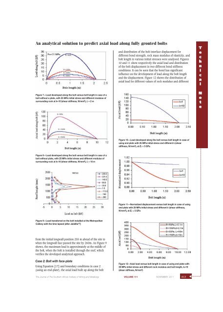
An analytical solution to predict axial load along fully grouted bolts<br />
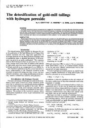
Figure 7—Load developed along <strong>the</strong> bolt versus bolt length in case <strong>of</strong> a<br />
bolt without a plate, with 25 MPa initial stress and different modulus <strong>of</strong><br />
surrounding rock at k=10 (shear stiffness, N/mm 2 ), L = 2 m<br />
and distribution <strong>of</strong> <strong>the</strong> bolt interface displacement for<br />
different bond strength, rock mass modulus <strong>of</strong> elasticity, and<br />
bolt length in various initial stresses were analysed. Figures<br />
10 and 11 show respectively <strong>the</strong> axial load and distribution<br />
<strong>of</strong> <strong>the</strong> bolt displacement in two different bond stiffness<br />
conditions. It can be seen that <strong>the</strong> bond has significant<br />
influence on <strong>the</strong> development <strong>of</strong> load along <strong>the</strong> bolt length<br />
and <strong>the</strong> displacement. Figure 12 shows <strong>the</strong> distribution <strong>of</strong><br />
axial load for different values <strong>of</strong> rock modulus and different<br />
T<br />
e<br />
c<br />
h<br />
n<br />
i<br />
c<br />
a<br />
l<br />
N<br />
o<br />
t<br />
e<br />
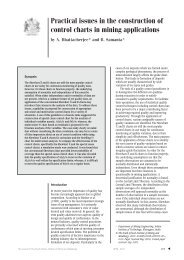
Figure 10—Load developed along <strong>the</strong> bolt versus bolt length in case <strong>of</strong><br />
using end plate with 25 MPa initial stress and different k (shear<br />
stiffness, N/mm 2 ), at Er = 5 GPa<br />
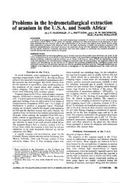
Figure 8—Load developed along <strong>the</strong> bolt versus bolt length in case <strong>of</strong> a<br />
bolt without plate, with 25 MPa initial stress and different modulus <strong>of</strong><br />
surrounding rock at k=10 (shear stiffness, N/mm 2 ), L = 10 m<br />
Figure 11—Normalized displacement versus bolt length in case <strong>of</strong> using<br />
end plate with 25 MPa initial stress and different k (shear stiffness,<br />
N/mm 2 ), at Er = 5 GPa<br />
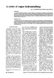
Figure 9—Load transferred on <strong>the</strong> bolt installed at <strong>the</strong> Metropolitan<br />
Colliery with <strong>the</strong> time lapsed (after Jalalifar 13 )<br />
from <strong>the</strong> initial longwall position 255 m ahead <strong>of</strong> <strong>the</strong> site to<br />
when <strong>the</strong> longwall face passed <strong>the</strong> site by 260m. As Figure 9<br />
shows, <strong>the</strong> maximum load is approximately at <strong>the</strong> middle <strong>of</strong><br />
<strong>the</strong> bolt, when <strong>the</strong> bolt is installed through <strong>the</strong> ro<strong>of</strong>, which<br />
verifies <strong>the</strong> developed analytical approach.<br />
Case 2: Bolt with face-plate<br />
Using Equation [17] and boundary conditions in case 2<br />
(using an end-plate), <strong>the</strong> axial load built up along <strong>the</strong> bolt<br />
Figure 12—Axial load versus bolt length in case <strong>of</strong> using end plate with<br />
25 MPa initial stress and different rock modulus and bolt length, k=10<br />
(shear stiffness, N/mm 2 )<br />
The Journal <strong>of</strong> The Sou<strong>the</strong>rn African Institute <strong>of</strong> Mining and Metallurgy VOLUME 111 NOVEMBER 2011 813<br />
▲