PCD2.H32.. MOTION CONTROL MODULES - SBC-support
PCD2.H32.. MOTION CONTROL MODULES - SBC-support
PCD2.H32.. MOTION CONTROL MODULES - SBC-support

Create successful ePaper yourself
Turn your PDF publications into a flip-book with our unique Google optimized e-Paper software.
PCD1<br />
PCD2<br />
xx7<br />
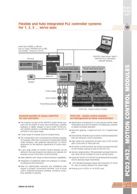
Flexible and fully integrated PLC controller systems<br />
for 1, 2, 3 … servo axes<br />
SAIA®S-Bus (RS485) or MPI for<br />
the xx7 Series, PROFIBUS DP or FMS,<br />
LON-WORKS®, Ethernet (TCP/IP)<br />
Terminal<br />
PG4/PG5, Web-Server, Step®7,<br />
SAIA®ViSi-PLUS, HMI editor,<br />
software libraries<br />
Modem<br />
Serie xx7<br />
Power stages<br />
Servo motors<br />
Transmitting devices<br />
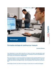
Essential benefits of using a SAIA®PCD<br />
for axis controllers<br />
¬ The modular concept of the SAIA®PCD system family <strong>support</strong>s<br />
the full extent of every drive technology: whether<br />
analogue or digital, stepper or servo motor (DC/BL/AC),<br />
and whether position is controlled centrally in the PLC or<br />
remotely in the power stage.<br />
¬ A wide range of modular tools for programming.<br />
¬ The configuration and commissioning software package,<br />
for example, offers the convenience of parameter setting<br />
under Windows, with graphical reproduction of motion<br />
sequences for the optimum adjustment of control parameters.<br />
¬ A very wide variety of motion control settings can be<br />
defined in the user program and called up as required, for<br />
example via one of the SAIA® control terminals.<br />
¬ Open platform with range of interconnection capa bilities.<br />
¬ Integration of additional digital and analogue I/O signals,<br />
counting and time functions.<br />
¬ Ideal for sophisticated machines and installations that<br />
require a compact, economical controller, such as those<br />
used in materials processing, handling, conveyors, mounting,<br />
assembly or packing.<br />
SAIA®PCD<br />
<strong>PCD2.H32.</strong>. motion control module<br />
<strong>PCD2.H32.</strong>. motion control modules<br />
are distinguished by these characteristics<br />
¬ Specification of trapezoid or S-curve velocity profiles; linear<br />
interpolation and synchronization of multiple axes; position<br />
or speed controlled operation.<br />
¬ Electronic gearing, 1 master axis and 1 to 7 coupled slave<br />
axes.<br />
¬ Extraordinary flexibility due to event-oriented breakpoints<br />
that can influence current movement.<br />
¬ High speed and positioning accuracy due to PID control<br />
with a cycle time of 100 µs per axis.<br />
¬ All motion control functions are carried out autonomously<br />
by the module, placing no load on the PCD CPU.<br />
¬ Velocity, target position, PID parameters and gear transmission<br />
ratios can be modified on the fly during motion.<br />
¬ Inputs for 24 VDC or 5 V/RS 422 incremental shaft encoders<br />
and SSI absolute angle transmitters.<br />
¬ ±10 V standard analogue output with resolution of 12 bits<br />
inc. sign, as velocity setpoint for power stage.<br />
¬ Driving up to 4 (PCD1) or 14 (PCD2) axes.<br />
<strong>PCD2.H32.</strong>. <strong>MOTION</strong> <strong>CONTROL</strong> <strong>MODULES</strong><br />
Edition 26/334 E2
PCD1<br />
PCD2<br />
xx7<br />
Ultimate controller integration for the most sophisticated<br />
motion functions<br />
With the <strong>PCD2.H32.</strong>. motion control<br />
module, each axis can be operated fully<br />
independently of any other and previously<br />
selected profiles can be modified<br />
on the fly.<br />
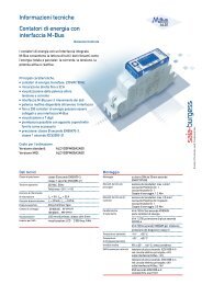
Position control mode<br />
The trapezoidal velocity profile is standard<br />
for many applications. It enables<br />
acceleration and deceleration to be set<br />
differently.<br />
v1<br />
v2<br />
v<br />
The S-surve velocity profile permits<br />
smooth motion sequences. The profile is<br />
predefined. Acceleration and deceleration<br />
have identical values.<br />
v<br />
v1<br />
24 V<br />
24 V<br />
24 V<br />
LS1<br />
24 V LS2<br />
24 V Ref<br />
24Vor5V<br />
M<br />
SSI-Data<br />
SSI-Data<br />
SSI-Clk<br />
SSI-Clk<br />
s1<br />
POWER<br />
AMPLIFIER<br />
SI<br />
SO<br />
A<br />
B<br />
IN<br />
±10V<br />
IN<br />
IN<br />
B<br />
B<br />
Destination<br />
position<br />
s2<br />
Speed control mode<br />
Acceleration, velocity and deceleration<br />
can be modified on the fly. A “Stop“<br />
command can be used to travel through<br />
a predefined deceleration ramp.<br />
9 LED PROM<br />
ENCODER-<br />
INTERFACE<br />
s<br />
Destination<br />
position<br />
s1<br />
s<br />
Electronic gearing<br />
Position information from the master<br />
axis serves to control the slave axis.<br />
This position information can be delivered<br />
either directly from the master axis<br />
transmitter or through the control of<br />
the master module. The transmission<br />
ratio extends from 1:65 535 to 65 535:1<br />
and can be modified on the fly.<br />
Breakpoints<br />
Each axis has two programmable breakpoints,<br />
each with 5 parameters and<br />
8 conditions. This allows specific functions<br />
to be integrated and parameters<br />
(e. g. target position, velocity, etc.) to<br />
be modified depending on axis status<br />
(e. g. position of another axis, velocity,<br />
time, etc.).<br />
Synchronization<br />
SI/SO inputs/outputs are deployed in<br />
connection with breakpoints.<br />
Flying cut<br />
This function is easy to realize, thanks to<br />
the module‘s great flexibility. It involves<br />
the insertion of on-the-fly connection<br />
or disconnection of electronic gearing<br />
and breakpoints.<br />
Status registers<br />
Each axis has registers available of 3 × 16<br />
bits to record certain states, events,<br />
motions, etc., which can be queried via<br />
the user program or which can directly<br />
influence the module.<br />
<strong>MOTION</strong><br />
PROCESSOR<br />
CHIP-SET<br />
(DSP+ASIC)<br />
TRAJECTORY<br />
GENERATION<br />
PID-<br />
REGULATION<br />
CLOCK<br />
40 MHz<br />
<strong>PCD2.H32.</strong>.<br />
<strong>CONTROL</strong> SIGNALS<br />
HOST DATABUS<br />
DATABUS<br />
TRACE<br />
MEMORY<br />
FIELD PRO-<br />
GRAMMABLE<br />
GATE ARRAY<br />
BUS-<br />
INTERFACE<br />
SERIAL/<br />
PARALLEL<br />
CONVERSION<br />
SSI-<br />
INTERFACE<br />
PCD1/2-BUS<br />
Motion parameters<br />
Registers with 32 bits are used for target<br />
position, velocity, acceleration and<br />
deceleration.<br />
Position: metric entry (unit selectable between<br />
1 µm and 1 m) or encoder pulses<br />
Velocity: metric entry (unit selectable<br />
between 1 µm/s and 1 m/s) or encoder<br />
pulses/s<br />
Acceleration: metric entry (unit selectable<br />
between 1 µm/s² and 1 m/s²) or<br />
encoder pulses/s²<br />
PID controller: sampling interval 100 µs<br />
per axis, proportional, integrative and<br />
derivative factors programmable, sampling<br />
interval for derivative part programmable<br />
separately, feed-forward for<br />
velocity and acceleration<br />
Trace memory<br />
This RAM memory of 2 × 256 kBit per<br />
module allows motions to be stored of<br />
1 s to 100 min, with up to 4 para me ters<br />
and max. 2000 data points (4 para meters<br />
with 500 each). This data can then be<br />
read and displayed graphically.<br />
Other functions<br />
These include stop commands, compensation<br />
voltage for vertical axes, openloop<br />
mode and automatic limit switch<br />
monitoring.<br />
PROCESSOR PCD1/2<br />
Block diagram<br />
of a servodrive for 1 axis<br />
(2 axes per module)<br />
PERFORMANCE OVERVIEW
PCD1<br />
PCD2<br />
xx7<br />
Comfortable configuring, programming and commissioning<br />
of the positioning modules<br />
This software package runs under Windows 98, 2000 and NT.<br />
In summary, it offers the following capabilities:<br />
¬ Direct, easy access to all basic functions<br />
¬ Effortless entry, testing and storage for a variety of motion<br />
parameters<br />
¬ Tracing and graphical representation of motion<br />
sequences<br />
¬ Comprehensive diagnostic functions<br />
¬ The PCD utilities, PG5, also allow the automatic integration<br />
of software libraries, initialization for programming and<br />
use of the new CSF instructions, which guarantee very fast<br />
processing of user cycles in the SAIA®PCD.<br />
The package can either be run as a stand-alone program,<br />
or integrated into the PG5 PCD utilities, or used together<br />
with Siemens‘ STEP®7 programming software. The following<br />
is intended to present some of the dialog boxes in more<br />
detail, various of which can also be used simultaneously.<br />
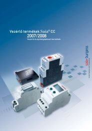
Entry of motion parameters<br />
This dialog box allows control parameters to be entered online,<br />
updated directly in the ..H32.. module and stored as<br />
backup. The right-hand column contains current values, which<br />
can be modified in the left-hand column.<br />
Diagnostic function<br />
The “Watch Window” offers the possibility of displaying online<br />
all data from the PCD (registers, flags, counters, etc.) and<br />
those of the ..H32.. module.<br />
Programming and testing different<br />
motion sequences<br />
With this dialog box it is possible, for example, quite simply<br />
to define a motion on-line and then process it (without<br />
knowledge of any programming language). Parameters and<br />
the motion sequence are entered and then the process type<br />
is selected.<br />
Recording control parameters and<br />
evaluating them graphically<br />
This dialog box defines which motion parameters to record<br />
in trace memory and how (up to 4 parameters per module).<br />
«One Time» means that tracing will end as soon as the memory<br />
is full. «Rolling Buffer» is used to refresh data in the memory<br />
continuously. The start and end of a trace can be set manually<br />
or event-controlled (e.g. by a breakpoint or state, such as<br />
«Target velocity reached»).<br />
The graphical display of motion follows automatically.<br />
PROGRAMMING AND COMMISSIONING
PCD1<br />
PCD2<br />
xx7<br />
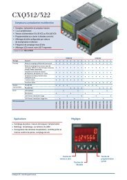
Technical data and ordering details<br />
Path recording with incremental shaft encoders _ _ _<br />
Number of inputs 6 per axis; A, B, IN and A, B, IN for ..H325<br />
Input signal 24 V or non-equivalent 5 V inputs, according to RS 422<br />
Count frequency max. 125 kHz with shaft encoder 24 V<br />
max. 250 kHz with shaft encoder 5 V/RS 422<br />
Count mode<br />
fourfold evaluation of input signals<br />
Encoder supply external or internal for ..H325<br />
Error detection possible with ..H325: cable break, encoder failure<br />
Path recording with SSI absolute angle transmitters<br />
SSI interfaces<br />
per axis 1 data input RS 422 (electrically isolated)<br />
and 1 clock output RS 422 (electrically connected)<br />
Resolution<br />
data bits selectable from 8 to 26 bits<br />
control bits selectable from 0 to 2 bits<br />
Count frequency 1 MHz (cable length þ20 m), 500 kHz (cable length 50 m),<br />
250 kHz (cable length 100 m)<br />
Data refresh<br />
every 100 µs at 1 MHz, 200 µs at 500 kHz,<br />
500 µs at 250kHz<br />
Data format<br />
gray or binary code<br />
Read mode<br />
normal (simple)<br />
Error detection transmitter failure (with 30 µs timeout)<br />
Digital inputs<br />
Number of inputs<br />
Input current<br />
Signal level<br />
Input delay<br />
Digital outputs<br />
Number of outputs<br />
Breaking capacity<br />
Potential drop<br />
Output delay<br />
Analogue outputs<br />
Number of channels<br />
Output signal<br />
Load resistance<br />
Ordering details<br />
Type<br />
Description<br />
per axis: 2 limit switches (LS1/LS2), 1 reference switch<br />
(Ref) and 1 input for synchronization (SI)<br />
8, electrically connected, negative logic<br />
7 mA at 24 V<br />
low = –30…5 V, high = 15…32 V<br />
300 µs at 24 V<br />
1 output per axis for synchronization (SO)<br />
2, electrically connected, short-circuit protected,<br />
source operation<br />
max. 0.5 A in range 6…32 VDC<br />
max. 0.3 V at 0.5 A<br />
typically 100 µs, max. 500 µs, under resistive load<br />
1 output per axis as velocity setpoint for driving the<br />
power amplifier<br />
2, electrically connected, with short-circuit protection<br />
±10 V, resolution 12 bit inc. sign bit<br />
ÿ3 kÞ<br />
LEDs for status indication and diagnosis<br />
Number of LEDs 8 per axis, indication of A, B, IN, Ref, LS1, LS2, SI, SO<br />
2 per module, indication of Power and OK<br />
Power supply<br />
External supply<br />
Internal supply<br />
Operating conditions<br />
Ambient temperature<br />
6…32 VDC smoothed, residual ripple max.10%, max.1 A<br />
(for outputs), without reverse battery protection<br />
5 VDC: 190…250 mA + shaft encoder supply for the<br />
..H325: max. 400 mA (electrically connected,<br />
with short-circuit protection)<br />
15 VDC: 10…16 mA<br />
operating: 0…+50 °C without forces ventilation<br />
storage: –20…+85 °C<br />
Noise emission CE mark according to EN 50081-1<br />
Noise immunity CE mark according to EN 50082-2<br />
Motion control modules for servodrives<br />
PCD2.H320 for 2 axes with incremental shaft encoders 24 VDC<br />
PCD2.H325 for 2 axes with incremental shaft encoders 5 V/RS 422<br />
or SSI absolute angle transmitters<br />
PCD2.H322 for 1 axis as slave with incremental shaft encoders 24 VDC<br />
PCD2.H327 for 1 axis as slave with incremental shaft encoders 5 V/RS 422<br />
or SSI absolute angle transmitters (only as slave)<br />
PCD8.Hx E Software package under Windows 95, 98, 2000, NT<br />
26/772 E Manual <strong>PCD2.H32.</strong>. for PCD<br />
PCD9.H32 E Software library with function blocks<br />
26/778 E Manual <strong>PCD2.H32.</strong>. for xx7<br />
Saia-Burgess<br />
Saia-Burgess Controls Ltd.<br />
Bahnhofstrasse 18<br />
CH-3280 Murten / Switzerland<br />
Telephone ++41 26 672 72 72<br />
Telefax ++41 26 672 74 99<br />
E-mail: pcd@saia-burgess.com<br />
Homepage: www.saia-burgess.com<br />
Your local contact:<br />
TECHNICAL DATA<br />
Printed in Switzerland 26/334 E2 06. 2001 TA20 Subject to change without notice.