Matching Networks and Phasing - Society of Broadcast Engineers
Matching Networks and Phasing - Society of Broadcast Engineers
Matching Networks and Phasing - Society of Broadcast Engineers

Create successful ePaper yourself
Turn your PDF publications into a flip-book with our unique Google optimized e-Paper software.
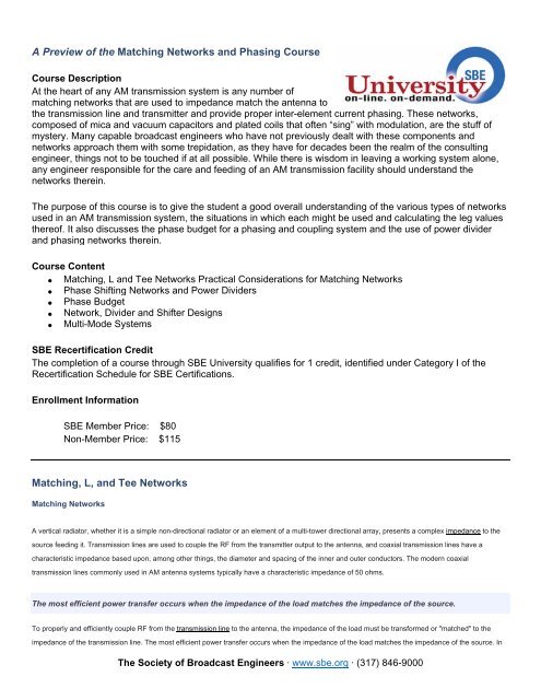
A Preview <strong>of</strong> the <strong>Matching</strong> <strong>Networks</strong> <strong>and</strong> <strong>Phasing</strong> Course<br />
Course Description<br />
At the heart <strong>of</strong> any AM transmission system is any number <strong>of</strong><br />
matching networks that are used to impedance match the antenna to<br />
the transmission line <strong>and</strong> transmitter <strong>and</strong> provide proper inter-element current phasing. These networks,<br />
composed <strong>of</strong> mica <strong>and</strong> vacuum capacitors <strong>and</strong> plated coils that <strong>of</strong>ten “sing” with modulation, are the stuff <strong>of</strong><br />
mystery. Many capable broadcast engineers who have not previously dealt with these components <strong>and</strong><br />
networks approach them with some trepidation, as they have for decades been the realm <strong>of</strong> the consulting<br />
engineer, things not to be touched if at all possible. While there is wisdom in leaving a working system alone,<br />
any engineer responsible for the care <strong>and</strong> feeding <strong>of</strong> an AM transmission facility should underst<strong>and</strong> the<br />
networks therein.<br />
The purpose <strong>of</strong> this course is to give the student a good overall underst<strong>and</strong>ing <strong>of</strong> the various types <strong>of</strong> networks<br />
used in an AM transmission system, the situations in which each might be used <strong>and</strong> calculating the leg values<br />
there<strong>of</strong>. It also discusses the phase budget for a phasing <strong>and</strong> coupling system <strong>and</strong> the use <strong>of</strong> power divider<br />
<strong>and</strong> phasing networks therein.<br />
Course Content<br />
<strong>Matching</strong>, L <strong>and</strong> Tee <strong>Networks</strong> Practical Considerations for <strong>Matching</strong> <strong>Networks</strong><br />
Phase Shifting <strong>Networks</strong> <strong>and</strong> Power Dividers<br />
Phase Budget<br />
Network, Divider <strong>and</strong> Shifter Designs<br />
Multi-Mode Systems<br />
SBE Recertification Credit<br />
The completion <strong>of</strong> a course through SBE University qualifies for 1 credit, identified under Category I <strong>of</strong> the<br />
Recertification Schedule for SBE Certifications.<br />
Enrollment Information<br />
SBE Member Price: $80<br />
Non-Member Price: $115<br />
<strong>Matching</strong>, L, <strong>and</strong> Tee <strong>Networks</strong><br />
<strong>Matching</strong> <strong>Networks</strong><br />
A vertical radiator, whether it is a simple non-directional radiator or an element <strong>of</strong> a multi-tower directional array, presents a complex impedance to the<br />
source feeding it. Transmission lines are used to couple the RF from the transmitter output to the antenna, <strong>and</strong> coaxial transmission lines have a<br />
characteristic impedance based upon, among other things, the diameter <strong>and</strong> spacing <strong>of</strong> the inner <strong>and</strong> outer conductors. The modern coaxial<br />
transmission lines commonly used in AM antenna systems typically have a characteristic impedance <strong>of</strong> 50 ohms.<br />
The most efficient power transfer occurs when the impedance <strong>of</strong> the load matches the impedance <strong>of</strong> the source.<br />
To properly <strong>and</strong> efficiently couple RF from the transmission line to the antenna, the impedance <strong>of</strong> the load must be transformed or "matched" to the<br />
impedance <strong>of</strong> the transmission line. The most efficient power transfer occurs when the impedance <strong>of</strong> the load matches the impedance <strong>of</strong> the source. In<br />
The <strong>Society</strong> <strong>of</strong> <strong>Broadcast</strong> <strong>Engineers</strong> · www.sbe.org · (317) 846-9000
addition to maximizing power delivery from source to load, VSWR b<strong>and</strong>width is significantly impacted by the source-load match. VSWR b<strong>and</strong>width, in<br />
turn, affects the audio b<strong>and</strong>width <strong>and</strong> thus the quality <strong>of</strong> the demodulated audio.<br />
Ideally, not only should the impedance <strong>of</strong> the load be matched to the impedance <strong>of</strong> the source, but the orientation <strong>of</strong> the load should also be correct. This<br />
is defined as a symmetrical arrangement <strong>of</strong> reduced resistance with equal but opposite reactance on either side <strong>of</strong> carrier. A Smith chart display <strong>of</strong> such<br />
an idealized load is shown in Figure 1.1. This orientation applies at the output <strong>of</strong> the transmitter power amplifier. Additional phase shifts in combining<br />
networks <strong>and</strong> filters will <strong>of</strong>ten result in the ideal orientation being considerably different at the transmitter output.<br />
The phase shift characteristic <strong>of</strong> the matching network is <strong>of</strong>ten used to properly rotate <strong>and</strong> orient the load. The individual leg reactances <strong>and</strong> reactance<br />
"slopes" are <strong>of</strong>ten used to properly shape the load.<br />
In in-b<strong>and</strong> on-channel (IBOC) digital systems, which employ 25 carriers in the 5 to 15 kHz range on either side <strong>of</strong> the analog carrier, b<strong>and</strong>width is even<br />
more important.<br />
In the simplest <strong>of</strong> situations, wherein the resistance <strong>of</strong> the antenna is 50 ohms, all that may be needed is a reactive component <strong>of</strong> an equal value <strong>and</strong><br />
opposite sign <strong>of</strong> the antenna reactance to "tune out" the reactance <strong>of</strong> the antenna. This would leave only the resistive component <strong>of</strong> the antenna<br />
impedance, thus presenting a "match" to the transmission line.<br />
Seldom do such situations occur, however. A typical radiator will exhibit a complex base or driving point impedance that has a resistance <strong>of</strong> some value<br />
other than 50 ohms along with a reactance. It is thus necessary to use a matching network to transform the resistance to 50 ohms <strong>and</strong> eliminate the<br />
reactance. This can be done with any <strong>of</strong> several types <strong>of</strong> networks: L, Tee or Pi. Pi networks are seldom used in AM antenna systems. L networks are<br />
well-suited to use in some non-directional antennas where the phase shift through the network is not as important. Tee networks are useful where<br />
control <strong>of</strong> phase is necessary in addition to impedance transformation.<br />
The <strong>Society</strong> <strong>of</strong> <strong>Broadcast</strong> <strong>Engineers</strong> · www.sbe.org · (317) 846-9000
A matching network will either advance (lead) the phase <strong>of</strong> the current through it or retard (lag) it. The configuration <strong>of</strong> leading <strong>and</strong> lagging L networks is<br />
shown below:<br />
Notice that the identifying characteristic <strong>of</strong> a leading L network is a capacitor on the input. Conversely, the identifying characteristic <strong>of</strong> a lagging L<br />
network is an inductor on the input.<br />
The configuration <strong>of</strong> leading <strong>and</strong> lagging Tee networks is shown below:<br />
Notice that in its simplest form as shown here, the identifying characteristic <strong>of</strong> a leading Tee network is an inductive reactance in the shunt leg.<br />
Conversely, a capacitive reactance in the shunt leg denotes a lagging configuration. These arrangements usually correspond to the opposite reactances<br />
in the series legs. In many cases, however, for the purpose <strong>of</strong> canceling inductive reactances in the load or input or for other reasons, there may be a<br />
combination <strong>of</strong> inductors <strong>and</strong> capacitors in the series arms <strong>of</strong> a practical Tee network. As such, it can be hard to identify whether such a network is a<br />
leading or lagging net by the series elements alone. The sure-fire way <strong>of</strong> identifying a Tee network is by the components in its shunt arm as noted<br />
above.<br />
The <strong>Society</strong> <strong>of</strong> <strong>Broadcast</strong> <strong>Engineers</strong> · www.sbe.org · (317) 846-9000