ODTF-1 - ELSINCO
ODTF-1 - ELSINCO
ODTF-1 - ELSINCO

Create successful ePaper yourself
Turn your PDF publications into a flip-book with our unique Google optimized e-Paper software.
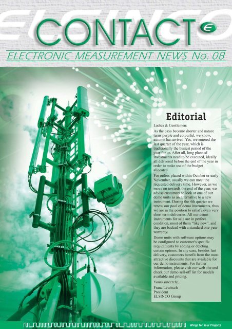
ELECTRONIC MEASUREMENT NEWS No. 08<br />
Editorial<br />
Ladies & Gentlemen:<br />
As the days become shorter and nature<br />
turns purple and colourful, we know,<br />
autumn has arrived. Yes, we entered the<br />
last quarter of the year, which is<br />
traditionally the busiest period of the<br />
year for us. After all, long planned<br />
investments need to be executed, ideally<br />
all delivered before the end of the year in<br />
order to make use of the budget<br />
allocated.<br />
For orders placed within October or early<br />
November, usually we can meet the<br />
requested delivery time. However, as we<br />
move on towards the end of the year, we<br />
advise customers to look at one of our<br />
demo units as an alternative to a new<br />
instrument. During the 4th quarter we<br />
renew our pool of demo instruments, thus<br />
we are in the position to satisfy even very<br />
short term deliveries. All our demo<br />
instruments for sale are in perfect<br />
condition, most of them “like new”, and<br />
they are backed with a standard one-year<br />
warranty.<br />
Demo units with software options may<br />
be configured to customer's specific<br />
requirements by adding or deleting<br />
certain options. In any case, besides fast<br />
delivery, customers benefit from the most<br />
attractive discounts that are available for<br />
our demo instruments. For further<br />
information, please visit our web site and<br />
check our demo sell-off list for models<br />
available and pricing.<br />
Yours sincerely,<br />
Franz Lewitsch<br />
President<br />
<strong>ELSINCO</strong> Group<br />
Wings for Your Projects
Technology News<br />
.<br />
Remote Radio Heads (RRHs)<br />
in Wireless Mobile Networks<br />
Mobile wireless networks are constantly<br />
evolving, so that users get new and better<br />
services. This requires continuous<br />
investments by the operators, who at the<br />
same time are fighting for each and every<br />
subscriber with most attractive tariffs.<br />
While this is fine for the users, as they<br />
get good services at low fees, this means<br />
a constant challenge for the operators,<br />
who are trying very hard to get the best<br />
from their network at affordable prices.<br />
.<br />
One of the latest developments which<br />
help operators to run their networks more<br />
efficiently, are the so called Remote<br />
Radio Heads (RRH).<br />
.<br />
In a traditional base station set-up, the<br />
Node B, which is located in a container<br />
on the ground, is connected to the<br />
antenna via RF coax cables, including a<br />
Tower Mounted Amplifier (TMA). The<br />
typical loss between a Node B and the<br />
Antenna is in the range of 3.5dB.<br />
.<br />
A base station that uses a Remote Radio<br />
Head offers several significant<br />
advantages compared to a traditional<br />
Base Station setup. A so called Radio<br />
Server is connected via optical fiber with<br />
the Remote Radio Head (RRH). Typical<br />
distances between the Radio Server on<br />
the ground and the antenna tower<br />
introduce insignificant loss on the optical<br />
fiber so that we can truly say it is a “loss<br />
Traditional<br />
Mode B<br />
Radio<br />
Server<br />
Jumper<br />
0,5 dB<br />
typically 3 dB<br />
7/8" Feeders<br />
15 m � 1,6 dB<br />
50% loss of output power<br />
optical fibre<br />
Jumper<br />
0,5 dB<br />
no loss of output power<br />
less” connection. Since the RRH is<br />
typically located on the antenna tower<br />
and close to the antenna, there is no need<br />
for a TMA. The only loss that is<br />
introduced is the connection between the<br />
RRH and the antenna, which is still done<br />
using a RF cable. With values of typically<br />
0.5dB, this means a 3db (50%) difference<br />
in the power levels transmitted by the<br />
Base Station! In other words, using a<br />
RRH, the power efficiency of the Base<br />
Station becomes<br />
much higher. This is<br />
only one advantage<br />
that speaks for using<br />
Remote Radio<br />
Heads. Besides that,<br />
due to the reduced<br />
power needed for<br />
transmission, less<br />
energy is required<br />
for cooling.<br />
Moreover, optical<br />
fibers are less<br />
expensive than RF cables, and TMAs are<br />
not required at all. That all adds up to<br />
significant cost savings. Therefore,<br />
“traditional” Base Stations are often<br />
replaced by Base Stations that use<br />
Remote Radio Heads, since the<br />
investment pays off in relatively short<br />
time.<br />
.<br />
.<br />
Testing Remote Radio Head<br />
Base Stations<br />
Up to now, technicians dealing with<br />
installation and<br />
maintenance of Base<br />
Stations typically<br />
have used a tool to<br />
TMA<br />
RRH<br />
Antenna<br />
Jumper<br />
0,5 dB<br />
Antenna<br />
Jumper<br />
0,5 dB<br />
check RF<br />
parameters of the<br />
RF cable between<br />
Node B and<br />
Antenna. (e.g. a<br />
Cable / Antenna<br />
Analyzer for Fault<br />
Location Analysis,<br />
Loss Measurements,<br />
etc.). With RRHs, an<br />
optical cable tester<br />
is required as well.<br />
.<br />
Source's<br />
Spectral<br />
Density<br />
Using a classical<br />
OTDR (Optical<br />
Time Domain<br />
Reflectometer) for<br />
the verification of<br />
the fiber between<br />
radio server and<br />
RRH can be<br />
TDR<br />
difficult, due to the attenuation dead zone<br />
of the OTDR.<br />
.<br />
Anritsu has developed a solution, which<br />
overcomes this issue by using an<br />
approach that is different from the<br />
measurement as done with a classical<br />
OTDR.<br />
.<br />
The <strong>ODTF</strong>-1 module, especially designed<br />
for Anritsu Site Master and BTS Master,<br />
is using FDR instead of TDR as used<br />
Less than 2% of<br />
TDR source energy<br />
is in the RF bands<br />
f1<br />
with OTDRs. Deadzones in an OTDR<br />
occur due to the reflected signals that<br />
saturate the photo receiver. The saturating<br />
signal is caused by high level optical<br />
pulses that are reflected due to the<br />
backscatter, which is dominated by low<br />
frequency content. In the frequency<br />
domain the photo receiver is only<br />
sensitive to optical signals with<br />
modulation in the microwave range.<br />
Thus, the photo receiver is not affected<br />
by backscatter overloading the receiver.<br />
Thus, with FDR there is no deadzone.<br />
.<br />
Anritsu Site Masters or BTS Masters<br />
equipped with the Optical Distance-to-<br />
Fault module <strong>ODTF</strong>-1 are the ideal test<br />
solution for Base Stations with RRH,<br />
since they perfectly combine a complete<br />
suite of test capabilities for RF coax<br />
cables and optical fibres all in a single<br />
handheld instrument. Thus, network<br />
operators, installers and maintenance<br />
technicians of base stations have to carry<br />
only one single light-weight instrument<br />
that is capable to analyze all parameters<br />
of any base station.<br />
.<br />
Anritsu Test Instruments for Base Station<br />
Installations:<br />
Fault Location on RF Coax Cables &<br />
Optical Fibers (S331D, S332D,<br />
MT8222A)<br />
Spectrum Analysis<br />
(MT8222A, S332D)<br />
Transmitter Analysis for GSM /<br />
GPRS / EDGE, W-CDMA / HSDPA,<br />
WiMax fixed / mobile (MT8222A)<br />
f2<br />
FDR<br />
Wings for Your Projects
Product News<br />
<strong>ODTF</strong>-1<br />
Optical Distance-to<br />
Fault Test Module for Site<br />
Master and BTS Master<br />
.<br />
.<br />
.<br />
.<br />
.<br />
.<br />
.<br />
.<br />
As mentioned in the technology article,<br />
many operators are moving towards<br />
implementation of base stations that<br />
utilize Remote Radio Heads. Anritsu's<br />
Optical Distance to Fault (<strong>ODTF</strong>) module<br />
addresses the need of these operators, as<br />
well as the need of installers and<br />
maintenance technicians to find the<br />
location of faults on RF cables AND on<br />
optical fibers.<br />
.<br />
The <strong>ODTF</strong>-1 uses wavelength of 1550nm<br />
to characterize Single Mode Fibers.<br />
It<br />
allows customers to make highly<br />
accurate measurements of fibers with a<br />
maximum distance of 1020m,<br />
with an<br />
event resolution of 10cm.<br />
Due to the<br />
measurement technique used by the<br />
<strong>ODTF</strong>-1, even the first centimeter of<br />
fibers can be tested accurately, because<br />
there are no deadzones,<br />
like usually<br />
found in standard Optical Time Domain<br />
Reflectometers (OTDRs)!<br />
.<br />
Technicians trained in the RF world will<br />
be able to start working with an <strong>ODTF</strong>-1<br />
equipped Site Master or BTS Master<br />
right away, since the RF Distance-to-<br />
Fault and the Optical Distance-to-Fault<br />
measurement modes are identical in their<br />
appearance and the results can be<br />
interpreted the same way.<br />
.<br />
Customers can upgrade their existing<br />
S331D/S332D Site Masters or MT8222A<br />
BTS Master cost effectively for optical<br />
fiber measurements by simply adding the<br />
<strong>ODTF</strong>-1 module.<br />
.<br />
More about the ANRITSU Site Master:<br />
http://www.elsinco.com/start.asp?ID=79<br />
.<br />
More about the ANRITSU BTS Master:<br />
http://www.elsinco.com/start.asp?ID=81<br />
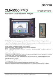
CMA5000A<br />
Multi-Technology Network<br />
Test Platform<br />
The CMA5000A is the successor to<br />
Anritsu's well established CMA5000 Test<br />
Platform. Similar like its predecessor, the<br />
CMA5000A is a portable, battery<br />
operated platform for testing a variety<br />
of transmission systems including<br />
Ethernet (from 10M to 10GE LAN<br />
and WAN)<br />
PDH/SDH/SONET (from E1/DS1<br />
to STM-64/OC-192)<br />
OTN (OTU-1 and OTU-2)<br />
Moreover, it is also capable to<br />
characterize optical fibers, including<br />
measurement of<br />
Fault Location (OTDR Optical Time<br />
Domain Reflectometry)<br />
Optical Spectrum Analysis (OSA)<br />
Polarization Mode Dispersion (PMD)<br />
Cromatic Dispersion (CD)<br />
The CMA5000A offers several improvements<br />
over the CMA5000, such as:<br />
Improved Touch Screen offering<br />
better readability even under direct<br />
sunlight<br />
Four USB2.0 ports for increased<br />
connectivity and usability (e.g.<br />
keyboard, mouse, printer, memory<br />
devices, etc ...)<br />
Built-in DVD, CD-RW drive<br />
Improved, more powerful CPU<br />
and more …<br />
The CMA5000A accepts all test modules<br />
that have previously been designed for<br />
use with the CMA5000.<br />
More about the ANRITSU CMA5000A:<br />
http://www.elsinco.com/start.asp?ID=143<br />
Product Flashlight<br />
Anritsu Introduced Thermal Power Sensors with Frequency Coverage Up to 50 GHz<br />
Site Master<br />
Now even faster and more<br />
accurate!<br />
The Anritsu Site Master Series of<br />
Cable & Antenna Analyzers, well known<br />
on the market for its most comprehensive<br />
measurement capabilities, are now even<br />
faster and more accurate!<br />
These new enhancements include:<br />
30% improvement in sweep speed<br />
With only 2.5ms / data point the Site<br />
Masters are the fastest handheld cable<br />
& antenna analyzers on the market!<br />
30% improvement in frequency<br />
accuracy<br />
now specified at 50ppm<br />
Frequency resolution specification<br />
improved by factor 100<br />
now 1kHz (instead of 100kHz).<br />
.<br />
Customers, who have purchased a Site<br />
Master S331D/S332D, S311D/S312D<br />
after February 2008 are able to benefit<br />
from the speed improvement as well –<br />
just easily download firmware version<br />
5.21 (or later) and install it on your Site<br />
Master!<br />
.<br />
Downloads for firmware upgrades of Site<br />
Master Instruments require Master<br />
Software Tools (MST).<br />
.<br />
To get your free copy of MST, please<br />
visit:<br />
http://www.us.anritsu.com/downloads/<br />
files/mst.exe<br />
.<br />
More about the ANRITSU Site Master<br />
http://www.elsinco.com/start.asp?ID=79<br />
Anritsu Introduced Peak Power Meters with Wide Bandwidth and High Sampling Rate<br />
More about the ANRITSU MA2400xA and the ANRITSU ML2480B:<br />
http://www.elsinco.com/start.asp?ID=100<br />
Wings for Your Projects<br />
.<br />
.<br />
.<br />
.<br />
.<br />
.<br />
.<br />
.<br />
.<br />
.<br />
.<br />
.<br />
.<br />
.<br />
.
Company News<br />
AMETEK acquires the Programmable Power Division of Xantrex<br />
AMETEK, Inc. has completed the<br />
acquisition of the programmable power<br />
business of Xantrex Technology, Inc.<br />
Based in San Diego, CA, Xantrex's<br />
Programmable Power Division is a leader<br />
in AC and DC programmable power<br />
supplies used to test electrical and<br />
electronics products by simulating<br />
various input voltages, frequencies and<br />
potentially harmful line transients.<br />
Its products are used in design<br />
verification testing, manufacturing,<br />
quality assurance and regulatory<br />
compliance testing.<br />
Up-coming Events / Exhibitions<br />
Electronic Measurement Technology<br />
Vienna<br />
Tel. 01-815 04 00<br />
office@elsinco.com<br />
Warsaw<br />
Tel. 022-832 40 42<br />
office@elsinco.pl<br />
Bratislava<br />
Tel. 02-6428 41 65<br />
office@elsinco.sk<br />
Budapest<br />
Tel. 01-339 00 00<br />
office@elsinco.hu<br />
Zagreb<br />
Tel. 01-631 24 77<br />
office@elsinco.hr<br />
R<br />
Ljubljana<br />
Tel. 01-434 20 50<br />
via-digital@via-digital.si<br />
Beograd<br />
Tel. 011-3046 440<br />
tetra@EUnet.yu<br />
Brno<br />
Tel. 0541-633 670<br />
info@trinstruments.cz<br />
"Xantrex Programmable Power is an<br />
excellent acquisition for AMETEK. It<br />
enjoys a strong reputation within the<br />
power industry and its products<br />
complement those offered by AMETEK<br />
Power Instruments," notes Frank S.<br />
Hermance, AMETEK Chairman and<br />
Chief Executive Officer. "<br />
Xantrex Programmable Power<br />
significantly expands our position in the<br />
niche market for programmable power<br />
sources and provides us with further<br />
opportunities for growth in the highly<br />
attractive electronic test and<br />
measurement equipment market," adds<br />
Mr. Hermance.<br />
We are looking very much forward seeing you at electronica 2008, Munich, Germany.<br />
Supplier<br />
Kikusui<br />
Ametek/Elgar/Sorensen<br />
Anritsu<br />
Hall / Booth Nr.<br />
A1.675<br />
A1.479<br />
A1.661<br />
In co-operation with:<br />
CompuMess Elektronik GmbH<br />
Your competent partner for intelligent<br />
Test & Measurement Solutions<br />
Bucureşti<br />
Tel. 021-322 74 40<br />
office@romkatel.ro<br />
Sofia<br />
Tel. 02-865 55 30<br />
test.com.elco@mbox.contact.bg<br />
Minsk<br />
Tel. 017-200 47 16<br />
tkc-misbos@tut.by<br />
Kiev<br />
Tel. 044-269 93 84<br />
info@sea.com.ua<br />
AMETEK is a leading global<br />
manufacturer of electronic instruments<br />
and electromechanical devices with<br />
annual sales of $2.5 billion. Xantrex<br />
Programmable Power joins AMETEK as<br />
part of its Electronic Instruments Group<br />
(EIG) --a recognized leader in advanced<br />
monitoring, testing, calibrating, and<br />
display instruments.<br />
The newly created AMETEK<br />
Programmable Power Division consists<br />
of the Xantrex Power Products with the<br />
Elgar, Sorensen and Power Ten brands as<br />
well as previously acquired California<br />
Instruments, thus offering the largest<br />
product portfolio in the industry.<br />
11–14 November<br />
Visit us: Hall A1, Booth 675<br />
Close to you …<br />
Wings for Your Projects