Automated Limit Testing Application Note - AFC Ingenieros
Automated Limit Testing Application Note - AFC Ingenieros
Automated Limit Testing Application Note - AFC Ingenieros

Create successful ePaper yourself
Turn your PDF publications into a flip-book with our unique Google optimized e-Paper software.
<strong>Application</strong> <strong>Note</strong><br />
<strong>Automated</strong> <strong>Limit</strong> <strong>Testing</strong><br />
<strong>Limit</strong> <strong>Testing</strong> with Tektronix DPO4000 and MSO4000<br />
Series Oscilloscopes and National Instruments<br />
LabVIEW SignalExpress TE for Windows<br />
TM<br />
Introduction<br />
<strong>Automated</strong> limit testing allows engineers and technicians to set up a pass/fail<br />
measurement on an electronic signal that automates the process of determining<br />
whether an acquired signal meets, or is within, a given set of criteria.
<strong>Automated</strong> <strong>Limit</strong> <strong>Testing</strong><br />
<strong>Application</strong> <strong>Note</strong><br />
Background<br />
A limit test typically consists of comparing a waveform to<br />
upper and lower boundaries which the measured waveform<br />
must not cross. These boundaries are typically defined by<br />
the user to specify a tolerance band around a waveform.<br />
If any part of the waveform falls outside the limit, the software<br />
returns a failure message and the location of the failure on<br />
the waveform.<br />
LabVIEW SignalExpress TE<br />
Configuration<br />
National Instruments LabVIEW SignalExpress TE (Tektronix<br />
Edition) requires no programming. There are many built-in<br />
steps available for immediate use in LabVIEW SignalExpress<br />
TE. For example, by inserting a signal acquisition step,<br />
the user can readily configure the appropriate oscilloscope<br />
and necessary input channel, vertical settings, horizontal<br />
settings, and triggering without writing a single line of code.<br />
A user can also quickly browse the settings for each instrument<br />
by leaving the Step Setup panel open and selecting<br />
different steps.<br />
Solving the Problem Quickly<br />
An engineer is working on new high speed embedded<br />
design. At this point, she is concerned that there may be<br />
a metastability in the system. One digital device’s output<br />
signal has the expected voltage amplitude, but she has<br />
noticed glitches on the output of the device. She suspects<br />
the glitches are being caused by setup and hold violations.<br />
The engineer concludes an automated limit test would be<br />
the quickest way to validate her speculation.<br />
The engineer begins by connecting the output of the device<br />
under test to CH1 of the Tektronix DPO4104 (1GHz, 5GS/s)<br />
oscilloscope. Next she sets up the oscilloscope with only two<br />
button pushes: Default Setup and Autoset, the waveform is<br />
ready for capture in LabVIEW SignalExpress TE. See Figure 1.<br />
With only a basic understanding of LabVIEW SignalExpress<br />
TE, the engineer begins the steps to configure an automated<br />
limit test. Connecting a USB cable from the scope to the<br />
computer brings up the LabVIEW SignalExpress TE open<br />
dialog box. See Figure 2. Clicking the OK button launches<br />
the LabVIEW SignalExpress TE program.<br />
Figure 1. Glitches seen, above, on the output waveform of the device under test.<br />
Figure 2. The LabVIEW SignalExpress TE dialog box automatically appears after<br />
connecting the oscilloscope to the computer via a USB cable, prompting the user to<br />
launch LabVIEW SignalExpress TE.<br />
2 www.tektronix.com/ni/signalexpress
<strong>Automated</strong> <strong>Limit</strong> <strong>Testing</strong><br />
<strong>Application</strong> <strong>Note</strong><br />
Figure 3. Tektronix DPO/MSO4000 Step Setup view with the Vertical tab selected.<br />
Figure 4. The Add Step button easily adds a <strong>Limit</strong> Test step.<br />
When the LabVIEW SignalExpress TE program opens, the<br />
Tektronix DPO/MSO4000 step inserts itself automatically.<br />
The engineer selects Run Once and the waveform appears<br />
on the display. See Figure 3.<br />
Next the engineer returns to the data view by selecting the<br />
Data View tab near the top of the screen.<br />
Now the engineer clicks and drags the DPO4000 (CH1)<br />
output to the Data View’s empty graph to view the<br />
CH1 data. She then clicks the Add Step button and selects<br />
Analysis > Test and Compare > <strong>Limit</strong> Test. See Figure 4.<br />
On the Configuration tab, she selects the following settings:<br />
User Defined Signals, Between <strong>Limit</strong>s, and Two <strong>Limit</strong>s,<br />
and then graphically defines the upper and lower test limits.<br />
www.tektronix.com/ni/signalexpress<br />
3
<strong>Automated</strong> <strong>Limit</strong> <strong>Testing</strong><br />
<strong>Application</strong> <strong>Note</strong><br />
The last step the engineer needs to<br />
complete is automating the limit test.<br />
This is accomplished by adding the<br />
Execution Control > Conditional<br />
Repeat step, then simply dragging the<br />
<strong>Limit</strong> Test step into the Conditional<br />
Repeat step. The setup menu for Input<br />
Configuration is displayed. The<br />
sequence of steps, in this case, is setup<br />
such that the test ends if a FALSE<br />
Boolean signal condition is met; otherwise,<br />
the loop is to repeat. See Figure 5.<br />
Finally, the Load/Save Signals > Save<br />
to ASCII/LVM step is added to save the<br />
violations to an ASCII file.<br />
Figure 5. The <strong>Limit</strong> Test step, in the Project View (left pane), is dragged and dropped into the Conditional Repeat<br />
step. The input Configuration menu, seen in the center pane, is used to repeat a sequence of steps inside the loop<br />
until one or more conditions are met. The variable can be a Boolean or scalar result.<br />
4 www.tektronix.com/ni/signalexpress
<strong>Automated</strong> <strong>Limit</strong> <strong>Testing</strong><br />
<strong>Application</strong> <strong>Note</strong><br />
Running the <strong>Limit</strong> Test<br />
The limit waveforms specify the pass/fail<br />
conditions. These are the initial values<br />
our engineer estimates to define an<br />
acceptable margin. She verifies her<br />
assumption by clicking the project<br />
Run button to run the test.<br />
The limit test application acquires<br />
waveforms and compares them to the<br />
boundary limits. If the signal crosses<br />
an upper or lower limit a violation occurs<br />
and shown on-screen in red, at the<br />
offending location. See Figure 6.<br />
Figure 6. Running the <strong>Automated</strong> <strong>Limit</strong> Test reveals violations seen in the Data View as red dots at the boundary<br />
crossings.<br />
www.tektronix.com/ni/signalexpress<br />
5
<strong>Automated</strong> <strong>Limit</strong> <strong>Testing</strong><br />
<strong>Application</strong> <strong>Note</strong><br />
Clicking on the Save to ASCII step<br />
displays the signal information, in the<br />
project pane. See Figure 7.<br />
Enabling channels 2 and 3, in the<br />
LabVIEW SignalExpress TE Tektronix<br />
DPO/MSO4000 Step Vertical pane,<br />
and dragging both channels into a new<br />
Data View pane, the engineer is able<br />
to see the system clock (ch2) and data<br />
(ch3), in relation to the output waveform<br />
(ch1). She reviews the results and<br />
concludes her speculation was correct:<br />
insufficient setup time between the<br />
system clock and data edge is causing<br />
the glitches at the output of the device<br />
under test. See Figure 8.<br />
Figure 7. Save to ASCII view, above, shows the limit test signal data. Because the choice “Overwrite once, then<br />
append to file” is selected every time the limit test is run, the signal data is appended to the existing text file, archiving<br />
the results for all test runs.<br />
Figure 8. Insufficient setup time between clock (ch2) and data (ch3), bottom pane above, is causing glitches on the<br />
on the output waveform (ch1) of the device under test, top pane above.<br />
6 www.tektronix.com/ni/signalexpress
<strong>Automated</strong> <strong>Limit</strong> <strong>Testing</strong><br />
<strong>Application</strong> <strong>Note</strong><br />
Conclusion<br />
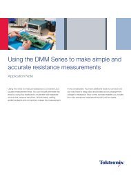
Until now, electronic design and test engineers, and<br />
technicians spent hours acquiring and analyzing electronic<br />
measurements manually. The advancing complexity of<br />
today’s electronic devices requires more tests to verify and<br />
validate a design without introducing additional time in the<br />
product development cycle.<br />
The Tektronix DPO4000 and MSO4000 Series oscilloscopes<br />
with the LabVIEW SignalExpress TE software package deliver<br />
a simple, interactive solution for limit testing various AC/DC<br />
electronic signal conditions. Engineers can use this powerful<br />
combination to save valuable time by automating measurements,<br />
and performing analysis, verification, characterization,<br />
and validation.<br />
www.tektronix.com/ni/signalexpress<br />
7
Contact Tektronix:<br />
ASEAN / Australasia (65) 6356 3900<br />
Austria +41 52 675 3777<br />
Balkans, Israel, South Africa and other ISE Countries +41 52 675 3777<br />
Belgium 07 81 60166<br />
Brazil & South America (11) 40669400<br />
Canada 1 (800) 661-5625<br />
Central East Europe, Ukraine and the Baltics +41 52 675 3777<br />
Central Europe & Greece +41 52 675 3777<br />
Denmark +45 80 88 1401<br />
Finland +41 52 675 3777<br />
France +33 (0) 1 69 86 81 81<br />
Germany +49 (221) 94 77 400<br />
Hong Kong (852) 2585-6688<br />
India (91) 80-22275577<br />
Italy +39 (02) 25086 1<br />
Japan 81 (3) 6714-3010<br />
Luxembourg +44 (0) 1344 392400<br />
Mexico, Central America & Caribbean 52 (55) 5424700<br />
Middle East, Asia and North Africa +41 52 675 3777<br />
The Netherlands 090 02 021797<br />
Norway 800 16098<br />
People’s Republic of China 86 (10) 6235 1230<br />
Poland +41 52 675 3777<br />
Portugal 80 08 12370<br />
Republic of Korea 82 (2) 6917-5000<br />
Russia & CIS +7 (495) 7484900<br />
South Africa +27 11 206 8360<br />
Spain (+34) 901 988 054<br />
Sweden 020 08 80371<br />
Switzerland +41 52 675 3777<br />
Taiwan 886 (2) 2722-9622<br />
United Kingdom & Eire +44 (0) 1344 392400<br />
USA 1 (800) 426-2200<br />
For other areas contact Tektronix, Inc. at: 1 (503) 627-7111<br />
Updated 12 November 2007<br />
For Further Information<br />
Tektronix maintains a comprehensive, constantly expanding<br />
collection of application notes, technical briefs and other<br />
resources to help engineers working on the cutting edge of<br />
technology. Please visit www.tektronix.com<br />
Copyright © 2008, Tektronix. All rights reserved. Tektronix products are covered<br />
by U.S. and foreign patents, issued and pending. Information in this publication<br />
supersedes that in all previously published material. Specification and price<br />
change privileges reserved. TEKTRONIX and TEK are registered trademarks<br />
of Tektronix, Inc. All other trade names referenced are the service marks,<br />
trademarks or registered trademarks of their respective companies.<br />
05/08 DM 3GW-20095-1