VCMS 6-Switch Panel Systems Owners Manuals ... - InPower Direct
VCMS 6-Switch Panel Systems Owners Manuals ... - InPower Direct
VCMS 6-Switch Panel Systems Owners Manuals ... - InPower Direct

Create successful ePaper yourself
Turn your PDF publications into a flip-book with our unique Google optimized e-Paper software.
InPOWER<br />
the systems people<br />
<strong>Owners</strong> Manual<br />
<strong>VCMS</strong> <strong>Switch</strong> <strong>Panel</strong> System<br />
Model <strong>VCMS</strong>-SP12<br />
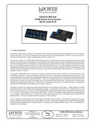
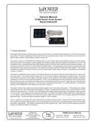
1. Product Description<br />
The <strong>Switch</strong> <strong>Panel</strong> System consists of a six-position switch module, a six output power module and a 15 ft. communications<br />
logic cable. It is used in applications that require the driver to operate auxiliary vehicle 12 volt devices such as interior and<br />
exterior lights, heaters, warning lights, beacons, pumps, etc.<br />
The system contains a <strong>VCMS</strong>-SM6 <strong>Switch</strong> Module with six push buttons that are back lighted to allow easy night viewing.<br />
Each push button accomodates a custom legend and contains a status LED that indicates if the switch is on or off. The<br />
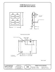
anodized aluminum case features a low profile measuring only 0.55 inches high, allowing mounting location flexibility. It is<br />
mounted to a flat panel via four 0.70 inch long 6-32 threaded studs. The case design is an aluminum two-piece clam shell<br />
held together by two screws on each side. The module can be easily opened to install the switch legends. The module<br />
contains a 10-position connector on the rear for the communications logic cable connection. A mounting cutout template<br />
is shown in Figure 3.<br />
The system’s <strong>VCMS</strong>-PM1 power module is remotely located from the switch module and connected with the communications<br />
logic cable. The power module contains six 12 volt 15 amp outputs for powering the auxiliary loads. The power<br />
module has a maximum current rating of 60 amps (total of all six outputs). The outputs provide automatic shutdown<br />
protection for short circuit and overload conditions. Three +12 volt (BAT) terminals are provided for the incoming power.<br />
Each terminal must be connected to the battery with an individually fused (20 amp) wire. Note that all six internal power<br />
switches are powered from a common 12 volt bus that is connected to the three +12 volt BAT terminals. A mechanical<br />
drawing of the <strong>VCMS</strong>-PM1 Power Module can be seen in Figure 4.<br />
The power module’s four digital inputs allow external signals to be monitored by the system. These signals are voltage<br />
levels between zero volts (chassis ground) and battery voltage. Typically these inputs are from a contact closure such as<br />
a switch to either ground or +12 volts. The <strong>VCMS</strong> application program defines each input as actuated by either a ground<br />
or +12 volt input. The program for this systems uses input I-1 to monitor the Ignition <strong>Switch</strong> status so it is activated by a<br />
+12 volt signal. Wiring terminations for the power outputs, digital inputs and the +12 volt supply utilize 0.25 inch faston<br />
blade terminals. The communications interface utilizes a 10-pin connector.<br />
Input I-1 (Ignition On) activates the switch back lights and enables switch operation. Each switch is programmed to operate<br />
as either a 2-position latching (push to turn on, push again to turn off) or as a momentary switch (on for the durration<br />
the switch is depressed). This system is programmed to have switches SW3 through SW5 operate as 2-position latching,<br />
and SW1 and SW2 as momentary.<br />
© Copyright 2009 <strong>InPower</strong> LLC<br />
<strong>InPower</strong> LLC<br />
3555 Africa Road<br />
Galena, Ohio 43021 USA<br />
740-548-0965<br />
www.<strong>InPower</strong><strong>Direct</strong>.com<br />
Page<br />
1 of 6<br />
<strong>VCMS</strong> <strong>Owners</strong> Manual<br />
Document: OM-139 Version Code: A<br />
Date: Oct. 27, 2010 Date: Oct. 27, 2010