VCMS 6-Switch Panel Systems Owners Manuals ... - InPower Direct
VCMS 6-Switch Panel Systems Owners Manuals ... - InPower Direct
VCMS 6-Switch Panel Systems Owners Manuals ... - InPower Direct

You also want an ePaper? Increase the reach of your titles
YUMPU automatically turns print PDFs into web optimized ePapers that Google loves.
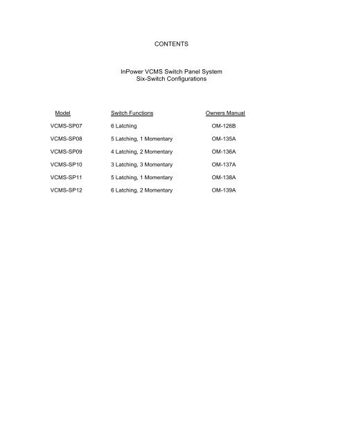
CONTENTS<br />
<strong>InPower</strong> <strong>VCMS</strong> <strong>Switch</strong> <strong>Panel</strong> System<br />
Six-<strong>Switch</strong> Configurations<br />
Model <strong>Switch</strong> Functions <strong>Owners</strong> Manual<br />
<strong>VCMS</strong>-SP07 6 Latching OM-126B<br />
<strong>VCMS</strong>-SP08 5 Latching, 1 Momentary OM-135A<br />
<strong>VCMS</strong>-SP09 4 Latching, 2 Momentary OM-136A<br />
<strong>VCMS</strong>-SP10 3 Latching, 3 Momentary OM-137A<br />
<strong>VCMS</strong>-SP11 5 Latching, 1 Momentary OM-138A<br />
<strong>VCMS</strong>-SP12 6 Latching, 2 Momentary OM-139A
InPOWER<br />
the systems people<br />
<strong>Owners</strong> Manual<br />
<strong>VCMS</strong> <strong>Switch</strong> <strong>Panel</strong> System<br />
Model <strong>VCMS</strong>-SP07<br />
1. Product Description<br />
The <strong>Switch</strong> <strong>Panel</strong> System consists of a six-position switch module, a six output power module and a 15 ft. communications<br />
logic cable. It is used in applications that require the driver to operate auxiliary vehicle 12 volt devices such as interior and<br />
exterior lights, heaters, warning lights, beacons, pumps, etc.<br />
The system contains a <strong>VCMS</strong>-SM6 <strong>Switch</strong> Module with six push buttons that are back lighted to allow easy night viewing.<br />
Each push button accomodates a custom legend and contains a status LED that indicates if the switch is on or off. The<br />
anodized aluminum case features a low profile measuring only 0.55 inches high, allowing mounting location flexibility. It is<br />
mounted to a flat panel via four 0.70 inch long 6-32 threaded studs. The case design is an aluminum two-piece clam shell<br />
held together by two screws on each side. The module can be easily opened to install the switch legends. The module<br />
contains a 10-position connector on the rear for the communications logic cable connection. A mounting cutout template<br />
is shown in Figure 3.<br />
The system’s <strong>VCMS</strong>-PM1 power module is remotely located from the switch module and connected with the communications<br />
logic cable. The power module contains six 12 volt 15 amp outputs for powering the auxiliary loads. The power<br />
module has a maximum current rating of 60 amps (total of all six outputs). The outputs provide automatic shutdown<br />
protection for short circuit and overload conditions. Three +12 volt (BAT) terminals are provided for the incoming power.<br />
Each terminal must be connected to the battery with an individually fused (20 amp) wire. Note that all six internal power<br />
switches are powered from a common 12 volt bus that is connected to the three +12 volt BAT terminals. A mechanical<br />
drawing of the <strong>VCMS</strong>-PM1 Power Module can be seen in Figure 4.<br />
The power module’s four digital inputs allow external signals to be monitored by the system. These signals are voltage<br />
levels between zero volts (chassis ground) and battery voltage. Typically these inputs are from a contact closure such as<br />
a switch to either ground or +12 volts. The <strong>VCMS</strong> application program defines each input as actuated by either a ground<br />
or +12 volt input. The program for this systems uses input I-1 to monitor the Ignition <strong>Switch</strong> status so it is activated by a<br />
+12 volt signal. Wiring terminations for the power outputs, digital inputs and the +12 volt supply utilize 0.25 inch faston<br />
blade terminals. The communications interface utilizes a 10-pin connector.<br />
Input I-1 (Ignition On) activates the switch back lights and enables switch operation. Each switch is programmed to operate<br />
as either a 2-position latching (push to turn on, push again to turn off) or as a momentary switch (on for the durration<br />
the switch is depressed). This system is programmed to have switches SW1 through SW6 operate as 2-position latching.<br />
© Copyright 2009 <strong>InPower</strong> LLC<br />
<strong>InPower</strong> LLC<br />
3555 Africa Road<br />
Galena, Ohio 43021 USA<br />
740-548-0965<br />
www.<strong>InPower</strong><strong>Direct</strong>.com<br />
Page<br />
1 of 6<br />
<strong>VCMS</strong> <strong>Owners</strong> Manual<br />
Document: OM-126 Version Code: B<br />
Date: Sept. 20, 2010 Date: Oct. 27, 2010
System Diagram<br />
SM6 <strong>Switch</strong> Module<br />
<strong>Switch</strong><br />
SW1<br />
<strong>Switch</strong><br />
SW3<br />
<strong>Switch</strong><br />
SW5<br />
Ignition <strong>Switch</strong><br />
+12 Volts<br />
Ground<br />
Logic Cable<br />
PM1 Power Module<br />
<strong>Switch</strong><br />
SW2<br />
<strong>Switch</strong><br />
SW4<br />
<strong>Switch</strong><br />
SW6<br />
Load #1<br />
Load #2<br />
Load #3<br />
Fuse<br />
Outputs 15 Amps Max.<br />
20<br />
Fuse<br />
20<br />
Fuse<br />
20<br />
Fuses not<br />
supplied with<br />
system.<br />
Load #4<br />
Load #5<br />
+12 V Battery<br />
Power Source<br />
(60 Amps Max.)<br />
Load #6<br />
FIgure 1<br />
6-Position <strong>Switch</strong> Module<br />
Logic Cable<br />
Connector<br />
2.74<br />
3.33<br />
Not to scale.<br />
Figure 2<br />
© Copyright 2009 <strong>InPower</strong> LLC<br />
<strong>InPower</strong> LLC<br />
3555 Africa Road<br />
Galena, Ohio 43021 USA<br />
740-548-0965<br />
www.<strong>InPower</strong><strong>Direct</strong>.com<br />
Page<br />
2 of 6<br />
<strong>VCMS</strong> <strong>Owners</strong> Manual<br />
Document: OM-126 Version Code: B<br />
Date: Sept. 20, 2010 Date: Oct. 27, 2010
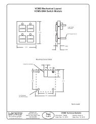
6-Position <strong>Switch</strong> Module<br />
Mounting Cutout Detail<br />
Cutout for connector<br />
0.50<br />
0.25<br />
0.38<br />
0.95<br />
1.50<br />
2.74<br />
0.16 Diameter<br />
(For #6-32 screw)<br />
2.00<br />
3.33<br />
Not to scale.<br />
Figure 3<br />
<strong>VCMS</strong>-PM1 Power Module<br />
Mod 1 R3<br />
Figure 4<br />
2. <strong>Switch</strong> Legends<br />
The <strong>Switch</strong> Modules design allows for easy installation of switch legends. Each push button switch contains a separate<br />
molded switch cap. A set of legend sheets is furnished with each system offering a wide variety of switch legend descriptions.<br />
A matrix of forty legends are printed on each sheet of special photographic paper. The desired legends are cut out,<br />
then placed in the switch caps, followed by the light diffusers. No adhesive is required. Figure 5 through Figure 10 shows<br />
the assembly stages of the switches.<br />
© Copyright 2009 <strong>InPower</strong> LLC<br />
<strong>InPower</strong> LLC<br />
3555 Africa Road<br />
Galena, Ohio 43021 USA<br />
740-548-0965<br />
www.<strong>InPower</strong><strong>Direct</strong>.com<br />
Page<br />
3 of 6<br />
<strong>VCMS</strong> <strong>Owners</strong> Manual<br />
Document: OM-126 Version Code: B<br />
Date: Sept. 20, 2010 Date: Oct. 27, 2010
4. <strong>Switch</strong> Legends Continued<br />
Figure 5 - <strong>Switch</strong> Module<br />
fully assembled.<br />
Figure 6 - <strong>Switch</strong> Module with<br />
top case removed.<br />
Figure 7 - <strong>Switch</strong> Cap with<br />
printed legend and light diffuser<br />
assembled.<br />
Figure 8 - <strong>Switch</strong> cap, printed<br />
legend and light diffuser.<br />
Figure 9 - <strong>Switch</strong> cap with<br />
printed legend installed.<br />
Figure 10 - <strong>Switch</strong> Cap with<br />
printed legend and light diffuser<br />
installed.<br />
3. Installation<br />
3.1 Getting Started<br />
Determine the best location for the switch module and the power module. Allow for the routing of the communications logic<br />
cable between the modules. We recommend installing the cable in a cable loom for protection. You will need a crimping<br />
tool for the 0.25 inch faston blade terminals. Be sure to follow the crimping tool instructions for the proper wire size and<br />
terminals. The <strong>VCMS</strong> Input/Output diagram (Figure 11) is a key reference document in that is shows how the modules are<br />
configured. It also should be used to capture the switch legend descriptions used and the names of the 12 volt auxiliary<br />
devices being controlled by the system. Complete this document and keep it for a record of the as installed system.<br />
3.2 Mount the <strong>Switch</strong> Module<br />
Mount the switch module on a flat surface or mounting bracket using the four #6-32 threaded studs to secure the module<br />
to the panel. You will need to make a cutout for the logic cable connector (See Figure 3). Connect the logic cable to the<br />
switch module and route the cable to the power module.<br />
3.3 Mount the Power Module<br />
3.3.1 Determine the best location for the power module. Take into consideration the routing of the interconnecting logic<br />
cable that attaches to the 10-pin connector on the top of the module. Also take into consideration the routing of the wires<br />
to the power outputs, inputs and the +12 volt fused power source.<br />
© Copyright 2009 <strong>InPower</strong> LLC<br />
<strong>InPower</strong> LLC<br />
3555 Africa Road<br />
Galena, Ohio 43021 USA<br />
740-548-0965<br />
www.<strong>InPower</strong><strong>Direct</strong>.com<br />
Page<br />
4 of 6<br />
<strong>VCMS</strong> <strong>Owners</strong> Manual<br />
Document: OM-126 Version Code: B<br />
Date: Sept. 20, 2010 Date: Oct. 27, 2010
3. Installation, Continued<br />
3.3 Mount the Power Module<br />
3.3.1 Determine the best location for the power module. Take into consideration the routing of the interconnecting logic<br />
cable that attaches to the 10-pin connector on the top of the module. Also take into consideration the routing of the wires<br />
to the power outputs, inputs and the +12 volt fused power source.<br />
3.3.2 We recommend mounting the power module to a flat metal surface. This allows the transfer of heat from the module<br />
when operating high current draw loads. Mount the module using four 6-32 screws and lock washers. Do not drill out<br />
the mounting holes to accept larger screw sizes. This will break the module’s ground connection. Do not over<br />
tighten the mounting screws.<br />
3.3.3 The wiring terminals on the power module are male ¼ inch faston blade terminals. You will need to attach insulated<br />
female terminals to the wires. Use a good quality crimping tool and follow the manufacturer’s instructions for the correct<br />
terminal types for the wire size.<br />
NOTE We recommend using wire tags that allow proper wire identification in the event the wires are removed at<br />
a later date.<br />
3.3.4 Wire the ground (GND) terminal to a good quality vehicle ground (Battery Negative). It is important that this<br />
ground is connected to the power module before the interconnecting logic cable is connected.<br />
3.3.5 Wire the six module output terminals (O-1, O-2, O-3, O-4, O-5 & O-6) to the correct auxiliary loads using the <strong>VCMS</strong><br />
Input/Output Diagram (Figure 11) for reference. Note that some outputs may not be used.<br />
NOTE If inductive loads (motors, coils, etc.) are used it is important that these devices contain a diode suppressor<br />
across the device.<br />
3.3.6 Wire the digital input terminal I-1 to a source of +12 volt power that is activated only when the Ignition <strong>Switch</strong> is On.<br />
3.3.7 Locate the +12 volt battery power source. Install three 20 amp fuses at the power source as shown on the system’s<br />
InPut/Output Diagram (Figure 1). Install wires of suitable size for the amperage and length from the three fuses to the three<br />
BAT terminals on the power module. Be sure to determine the current draw of the six power outputs to ensure that<br />
the power module is not overloaded. The maximum current draw of the combined loads cannot exceed 60 amps.<br />
If the +12 volt power source is directly connected to the vehicle battery, note that a <strong>VCMS</strong> configuration with a single power<br />
module with all switches and back lights off will draw about 16 milliamps of power. Alternatively, you may obtain the +12<br />
volts power from an ignition switch-activated power source.<br />
4. Operation<br />
Turn the Ignition <strong>Switch</strong> to the On position. The switch module’s back lights will illuminate.<br />
Operating any push button on the switch module will cause its status LED to turn on and the corresponding power module<br />
output to be activated. Each switch is programmed to operate as either a 2-position latching (push to turn on, push again<br />
to turn off) or as a momentary switch (on for the durration the switch is depressed). This system is programmed aas follows.<br />
<strong>Switch</strong> <strong>Switch</strong> Function Power Module Output<br />
SW1 2-Position Latching O-1<br />
SW2 2-Position Latching O-2<br />
SW3 2-Position Latching O-3<br />
SW4 2-Position Latching O-4<br />
SW5 2-Position Latching O-5<br />
SW1 2-Position Latching O-6<br />
Note that if a switch is activated and the Ignition <strong>Switch</strong> is turned off the power module output will turn off and the switch<br />
will be reset to its Off position.<br />
© Copyright 2009 <strong>InPower</strong> LLC<br />
<strong>InPower</strong> LLC<br />
3555 Africa Road<br />
Galena, Ohio 43021 USA<br />
740-548-0965<br />
www.<strong>InPower</strong><strong>Direct</strong>.com<br />
Page<br />
5 of 6<br />
<strong>VCMS</strong> <strong>Owners</strong> Manual<br />
Document: OM-126 Version Code: B<br />
Date: Sept. 20, 2010 Date: Oct. 27, 2010
<strong>VCMS</strong>-SP07 System Input/Output Diagram<br />
<strong>Switch</strong> Module<br />
<strong>Switch</strong> Legend<br />
SW1: ________________________________<br />
<strong>Switch</strong> Function<br />
2-Position Latching (Off_On1)<br />
SW1<br />
SW3<br />
SW5<br />
SW2: ________________________________<br />
2-Position Latching (Off_On1)<br />
SW3: ________________________________<br />
2-Position Latching (Off_On1)<br />
SW2<br />
SW4<br />
SW6<br />
SW4: ________________________________<br />
2-Position Latching (Off_On1)<br />
SW5: ________________________________<br />
2-Position Latching (Off_On1)<br />
SW6: ________________________________<br />
2-Position Latching (Off_On1)<br />
Logic Cable (15 ft.)<br />
<strong>VCMS</strong>-PM1 Power Module (MOD1)<br />
System Outputs<br />
System Inputs<br />
O-1 _____________________________ ( _____ Amps)<br />
Ignition On (+12 V)<br />
I-1<br />
BAT<br />
O-2 _____________________________ ( _____ Amps)<br />
Unused<br />
I-2<br />
O-3 _____________________________ ( _____ Amps)<br />
Unused<br />
Unused<br />
I-3<br />
I-4<br />
GND<br />
BAT<br />
O-4 _____________________________ ( _____ Amps)<br />
O-5 _____________________________ ( _____ Amps)<br />
BAT<br />
O-6 _____________________________ ( _____ Amps)<br />
Ground<br />
20<br />
20 +12 Volt Battery<br />
20<br />
Fuses not supplied with system.<br />
Power Module Input Assignments<br />
Input Function<br />
I-1 Ignition On (+12 Volt True)<br />
I-2 Unused<br />
I-3 Unused<br />
I-4 Unused<br />
Power Module Output Assignments<br />
Output Activated By<br />
O-1 SW1 + I-1<br />
O-2 SW2 + I-1<br />
O-3 SW5 + I-1<br />
O-4 SW4 + I-1<br />
O-5 SW5 + I-1<br />
O-6 SW6 + I-1<br />
Complete this form to document the system as installed.<br />
Project: _____________________________________ Date: ______________ System Model Number: ____________<br />
Figure 11<br />
© Copyright 2009 <strong>InPower</strong> LLC<br />
<strong>InPower</strong> LLC<br />
3555 Africa Road<br />
Galena, Ohio 43021 USA<br />
740-548-0965<br />
www.<strong>InPower</strong><strong>Direct</strong>.com<br />
Page<br />
6 of 6<br />
<strong>VCMS</strong> <strong>Owners</strong> Manual<br />
Document: OM-126 Version Code: B<br />
Date: Sept. 20, 2010 Date: Oct. 27, 2010
InPOWER<br />
the systems people<br />
<strong>Owners</strong> Manual<br />
<strong>VCMS</strong> <strong>Switch</strong> <strong>Panel</strong> System<br />
Model <strong>VCMS</strong>-SP08<br />
1. Product Description<br />
The <strong>Switch</strong> <strong>Panel</strong> System consists of a six-position switch module, a six output power module and a 15 ft. communications<br />
logic cable. It is used in applications that require the driver to operate auxiliary vehicle 12 volt devices such as interior and<br />
exterior lights, heaters, warning lights, beacons, pumps, etc.<br />
The system contains a <strong>VCMS</strong>-SM6 <strong>Switch</strong> Module with six push buttons that are back lighted to allow easy night viewing.<br />
Each push button accomodates a custom legend and contains a status LED that indicates if the switch is on or off. The<br />
anodized aluminum case features a low profile measuring only 0.55 inches high, allowing mounting location flexibility. It is<br />
mounted to a flat panel via four 0.70 inch long 6-32 threaded studs. The case design is an aluminum two-piece clam shell<br />
held together by two screws on each side. The module can be easily opened to install the switch legends. The module<br />
contains a 10-position connector on the rear for the communications logic cable connection. A mounting cutout template<br />
is shown in Figure 3.<br />
The system’s <strong>VCMS</strong>-PM1 power module is remotely located from the switch module and connected with the communications<br />
logic cable. The power module contains six 12 volt 15 amp outputs for powering the auxiliary loads. The power<br />
module has a maximum current rating of 60 amps (total of all six outputs). The outputs provide automatic shutdown<br />
protection for short circuit and overload conditions. Three +12 volt (BAT) terminals are provided for the incoming power.<br />
Each terminal must be connected to the battery with an individually fused (20 amp) wire. Note that all six internal power<br />
switches are powered from a common 12 volt bus that is connected to the three +12 volt BAT terminals. A mechanical<br />
drawing of the <strong>VCMS</strong>-PM1 Power Module can be seen in Figure 4.<br />
The power module’s four digital inputs allow external signals to be monitored by the system. These signals are voltage<br />
levels between zero volts (chassis ground) and battery voltage. Typically these inputs are from a contact closure such as<br />
a switch to either ground or +12 volts. The <strong>VCMS</strong> application program defines each input as actuated by either a ground<br />
or +12 volt input. The program for this systems uses input I-1 to monitor the Ignition <strong>Switch</strong> status so it is activated by a<br />
+12 volt signal. Wiring terminations for the power outputs, digital inputs and the +12 volt supply utilize 0.25 inch faston<br />
blade terminals. The communications interface utilizes a 10-pin connector.<br />
Input I-1 (Ignition On) activates the switch back lights and enables switch operation. Each switch is programmed to operate<br />
as either a 2-position latching (push to turn on, push again to turn off) or as a momentary switch (on for the durration<br />
the switch is depressed). This system is programmed to have switches SW1 through SW5 operate as 2-position latching<br />
and SW6 as momentary.<br />
© Copyright 2009 <strong>InPower</strong> LLC<br />
<strong>InPower</strong> LLC<br />
3555 Africa Road<br />
Galena, Ohio 43021 USA<br />
740-548-0965<br />
www.<strong>InPower</strong><strong>Direct</strong>.com<br />
Page<br />
1 of 6<br />
<strong>VCMS</strong> <strong>Owners</strong> Manual<br />
Document: OM-135 Version Code: A<br />
Date: Oct. 27, 2010 Date: Oct. 27, 2010
System Diagram<br />
SM6 <strong>Switch</strong> Module<br />
<strong>Switch</strong><br />
SW1<br />
<strong>Switch</strong><br />
SW3<br />
<strong>Switch</strong><br />
SW5<br />
Ignition <strong>Switch</strong><br />
+12 Volts<br />
Ground<br />
Logic Cable<br />
PM1 Power Module<br />
<strong>Switch</strong><br />
SW2<br />
<strong>Switch</strong><br />
SW4<br />
<strong>Switch</strong><br />
SW6<br />
Load #1<br />
Load #2<br />
Load #3<br />
Fuse<br />
Outputs 15 Amps Max.<br />
20<br />
Fuse<br />
20<br />
Fuse<br />
20<br />
Fuses not<br />
supplied with<br />
system.<br />
Load #4<br />
Load #5<br />
+12 V Battery<br />
Power Source<br />
(60 Amps Max.)<br />
Load #6<br />
FIgure 1<br />
6-Position <strong>Switch</strong> Module<br />
Logic Cable<br />
Connector<br />
2.74<br />
3.33<br />
Not to scale.<br />
Figure 2<br />
© Copyright 2009 <strong>InPower</strong> LLC<br />
<strong>InPower</strong> LLC<br />
3555 Africa Road<br />
Galena, Ohio 43021 USA<br />
740-548-0965<br />
www.<strong>InPower</strong><strong>Direct</strong>.com<br />
Page<br />
2 of 6<br />
<strong>VCMS</strong> <strong>Owners</strong> Manual<br />
Document: OM-135 Version Code: A<br />
Date: Oct. 27, 2010 Date: Oct. 27, 2010
6-Position <strong>Switch</strong> Module<br />
Mounting Cutout Detail<br />
Cutout for connector<br />
0.50<br />
0.25<br />
0.38<br />
0.95<br />
1.50<br />
2.74<br />
0.16 Diameter<br />
(For #6-32 screw)<br />
2.00<br />
3.33<br />
Not to scale.<br />
Figure 3<br />
<strong>VCMS</strong>-PM1 Power Module<br />
Mod 1 R3<br />
Figure 4<br />
2. <strong>Switch</strong> Legends<br />
The <strong>Switch</strong> Modules design allows for easy installation of switch legends. Each push button switch contains a separate<br />
molded switch cap. A set of legend sheets is furnished with each system offering a wide variety of switch legend descriptions.<br />
A matrix of forty legends are printed on each sheet of special photographic paper. The desired legends are cut out,<br />
then placed in the switch caps, followed by the light diffusers. No adhesive is required. Figure 5 through Figure 10 shows<br />
the assembly stages of the switches.<br />
© Copyright 2009 <strong>InPower</strong> LLC<br />
<strong>InPower</strong> LLC<br />
3555 Africa Road<br />
Galena, Ohio 43021 USA<br />
740-548-0965<br />
www.<strong>InPower</strong><strong>Direct</strong>.com<br />
Page<br />
3 of 6<br />
<strong>VCMS</strong> <strong>Owners</strong> Manual<br />
Document: OM-135 Version Code: A<br />
Date: Oct. 27, 2010 Date: Oct. 27, 2010
4. <strong>Switch</strong> Legends Continued<br />
Figure 5 - <strong>Switch</strong> Module<br />
fully assembled.<br />
Figure 6 - <strong>Switch</strong> Module with<br />
top case removed.<br />
Figure 7 - <strong>Switch</strong> Cap with<br />
printed legend and light diffuser<br />
assembled.<br />
Figure 8 - <strong>Switch</strong> cap, printed<br />
legend and light diffuser.<br />
Figure 9 - <strong>Switch</strong> cap with<br />
printed legend installed.<br />
Figure 10 - <strong>Switch</strong> Cap with<br />
printed legend and light diffuser<br />
installed.<br />
3. Installation<br />
3.1 Getting Started<br />
Determine the best location for the switch module and the power module. Allow for the routing of the communications logic<br />
cable between the modules. We recommend installing the cable in a cable loom for protection. You will need a crimping<br />
tool for the 0.25 inch faston blade terminals. Be sure to follow the crimping tool instructions for the proper wire size and<br />
terminals. The <strong>VCMS</strong> Input/Output diagram (Figure 11) is a key reference document in that is shows how the modules are<br />
configured. It also should be used to capture the switch legend descriptions used and the names of the 12 volt auxiliary<br />
devices being controlled by the system. Complete this document and keep it for a record of the as installed system.<br />
3.2 Mount the <strong>Switch</strong> Module<br />
Mount the switch module on a flat surface or mounting bracket using the four #6-32 threaded studs to secure the module<br />
to the panel. You will need to make a cutout for the logic cable connector (See Figure 3). Connect the logic cable to the<br />
switch module and route the cable to the power module.<br />
3.3 Mount the Power Module<br />
3.3.1 Determine the best location for the power module. Take into consideration the routing of the interconnecting logic<br />
cable that attaches to the 10-pin connector on the top of the module. Also take into consideration the routing of the wires<br />
to the power outputs, inputs and the +12 volt fused power source.<br />
© Copyright 2009 <strong>InPower</strong> LLC<br />
<strong>InPower</strong> LLC<br />
3555 Africa Road<br />
Galena, Ohio 43021 USA<br />
740-548-0965<br />
www.<strong>InPower</strong><strong>Direct</strong>.com<br />
Page<br />
4 of 6<br />
<strong>VCMS</strong> <strong>Owners</strong> Manual<br />
Document: OM-135 Version Code: A<br />
Date: Oct. 27, 2010 Date: Oct. 27, 2010
3. Installation, Continued<br />
3.3 Mount the Power Module<br />
3.3.1 Determine the best location for the power module. Take into consideration the routing of the interconnecting logic<br />
cable that attaches to the 10-pin connector on the top of the module. Also take into consideration the routing of the wires<br />
to the power outputs, inputs and the +12 volt fused power source.<br />
3.3.2 We recommend mounting the power module to a flat metal surface. This allows the transfer of heat from the module<br />
when operating high current draw loads. Mount the module using four 6-32 screws and lock washers. Do not drill out<br />
the mounting holes to accept larger screw sizes. This will break the module’s ground connection. Do not over<br />
tighten the mounting screws.<br />
3.3.3 The wiring terminals on the power module are male ¼ inch faston blade terminals. You will need to attach insulated<br />
female terminals to the wires. Use a good quality crimping tool and follow the manufacturer’s instructions for the correct<br />
terminal types for the wire size.<br />
NOTE We recommend using wire tags that allow proper wire identification in the event the wires are removed at<br />
a later date.<br />
3.3.4 Wire the ground (GND) terminal to a good quality vehicle ground (Battery Negative). It is important that this<br />
ground is connected to the power module before the interconnecting logic cable is connected.<br />
3.3.5 Wire the six module output terminals (O-1, O-2, O-3, O-4, O-5 & O-6) to the correct auxiliary loads using the <strong>VCMS</strong><br />
Input/Output Diagram (Figure 11) for reference. Note that some outputs may not be used.<br />
NOTE If inductive loads (motors, coils, etc.) are used it is important that these devices contain a diode suppressor<br />
across the device.<br />
3.3.6 Wire the digital input terminal I-1 to a source of +12 volt power that is activated only when the Ignition <strong>Switch</strong> is On.<br />
3.3.7 Locate the +12 volt battery power source. Install three 20 amp fuses at the power source as shown on the system’s<br />
InPut/Output Diagram (Figure 1). Install wires of suitable size for the amperage and length from the three fuses to the three<br />
BAT terminals on the power module. Be sure to determine the current draw of the six power outputs to ensure that<br />
the power module is not overloaded. The maximum current draw of the combined loads cannot exceed 60 amps.<br />
If the +12 volt power source is directly connected to the vehicle battery, note that a <strong>VCMS</strong> configuration with a single power<br />
module with all switches and back lights off will draw about 16 milliamps of power. Alternatively, you may obtain the +12<br />
volts power from an ignition switch-activated power source.<br />
4. Operation<br />
Turn the Ignition <strong>Switch</strong> to the On position. The switch module’s back lights will illuminate.<br />
Operating any push button on the switch module will cause its status LED to turn on and the corresponding power module<br />
output to be activated. Each switch is programmed to operate as either a 2-position latching (push to turn on, push again to<br />
turn off) or as a momentary switch (on for the durration the switch is depressed). This system is programmed as follows.<br />
<strong>Switch</strong> <strong>Switch</strong> Function Power Module Output<br />
SW1 2-Position Latching O-1<br />
SW2 2-Position Latching O-2<br />
SW3 2-Position Latching O-3<br />
SW4 2-Position Latching O-4<br />
SW5 2-Position Latching O-5<br />
SW6 Momentary O-6<br />
Note that if a switch is activated and the Ignition <strong>Switch</strong> is turned off the power module output will turn off and the switch<br />
will be reset to its Off position.<br />
© Copyright 2009 <strong>InPower</strong> LLC<br />
<strong>InPower</strong> LLC<br />
3555 Africa Road<br />
Galena, Ohio 43021 USA<br />
740-548-0965<br />
www.<strong>InPower</strong><strong>Direct</strong>.com<br />
Page<br />
5 of 6<br />
<strong>VCMS</strong> <strong>Owners</strong> Manual<br />
Document: OM-135 Version Code: A<br />
Date: Oct. 27, 2010 Date: Oct. 27, 2010
<strong>VCMS</strong>-SP08 System Input/Output Diagram<br />
<strong>Switch</strong> Module<br />
<strong>Switch</strong> Legend<br />
SW1: _______________________________<br />
<strong>Switch</strong> Function<br />
2-Position Latching (Off_On1)<br />
SW1<br />
SW3<br />
SW5<br />
SW2: _______________________________<br />
2-Position Latching (Off_On1)<br />
SW3: _______________________________<br />
2-Position Latching (Off_On1)<br />
SW2<br />
SW4<br />
SW6<br />
SW4: _______________________________<br />
2-Position Latching (Off_On1)<br />
SW5: _______________________________<br />
2-Position Latching (Off_On1)<br />
SW6: ________________________________<br />
Momentary<br />
Logic Cable (15 ft.)<br />
<strong>VCMS</strong>-PM1 Power Module (MOD1)<br />
System Outputs<br />
System Inputs<br />
O-1 _________________________ ( _____ Amps)<br />
Ignition On (+12 V)<br />
I-1<br />
BAT<br />
O-2 _________________________ ( _____ Amps)<br />
Unused<br />
I-2<br />
O-3 _________________________ ( _____ Amps)<br />
Unused<br />
Unused<br />
I-3<br />
I-4<br />
GND<br />
BAT<br />
O-4 _________________________ ( _____ Amps)<br />
O-5 _________________________ ( _____ Amps)<br />
BAT<br />
O-6 _________________________ ( _____ Amps)<br />
Ground<br />
20<br />
20<br />
20<br />
+12 Volt Battery<br />
Fuses not supplied with system.<br />
Power Module Input Assignments<br />
Input Function<br />
I-1 Ignition On (+12 Volt True)<br />
I-2 Unused<br />
I-3 Unused<br />
I-4 Unused<br />
Power Module Output Assignments<br />
Output Activated By<br />
O-1 SW1 + I-1<br />
O-2 SW2 + I-1<br />
O-3 SW5 + I-1<br />
O-4 SW4 + I-1<br />
O-5 SW5 + I-1<br />
O-6 SW6 + I-1<br />
Customer Project:________________________________ Date__________<br />
Figure 11<br />
© Copyright 2009 <strong>InPower</strong> LLC<br />
<strong>InPower</strong> LLC<br />
3555 Africa Road<br />
Galena, Ohio 43021 USA<br />
740-548-0965<br />
www.<strong>InPower</strong><strong>Direct</strong>.com<br />
Page<br />
6 of 6<br />
<strong>VCMS</strong> <strong>Owners</strong> Manual<br />
Document: OM-135 Version Code: A<br />
Date: Oct. 27, 2010 Date: Oct. 27, 2010
InPOWER<br />
the systems people<br />
<strong>Owners</strong> Manual<br />
<strong>VCMS</strong> <strong>Switch</strong> <strong>Panel</strong> System<br />
Model <strong>VCMS</strong>-SP09<br />
1. Product Description<br />
The <strong>Switch</strong> <strong>Panel</strong> System consists of a six-position switch module, a six output power module and a 15 ft. communications<br />
logic cable. It is used in applications that require the driver to operate auxiliary vehicle 12 volt devices such as interior and<br />
exterior lights, heaters, warning lights, beacons, pumps, etc.<br />
The system contains a <strong>VCMS</strong>-SM6 <strong>Switch</strong> Module with six push buttons that are back lighted to allow easy night viewing.<br />
Each push button accomodates a custom legend and contains a status LED that indicates if the switch is on or off. The<br />
anodized aluminum case features a low profile measuring only 0.55 inches high, allowing mounting location flexibility. It is<br />
mounted to a flat panel via four 0.70 inch long 6-32 threaded studs. The case design is an aluminum two-piece clam shell<br />
held together by two screws on each side. The module can be easily opened to install the switch legends. The module<br />
contains a 10-position connector on the rear for the communications logic cable connection. A mounting cutout template<br />
is shown in Figure 3.<br />
The system’s <strong>VCMS</strong>-PM1 power module is remotely located from the switch module and connected with the communications<br />
logic cable. The power module contains six 12 volt 15 amp outputs for powering the auxiliary loads. The power<br />
module has a maximum current rating of 60 amps (total of all six outputs). The outputs provide automatic shutdown<br />
protection for short circuit and overload conditions. Three +12 volt (BAT) terminals are provided for the incoming power.<br />
Each terminal must be connected to the battery with an individually fused (20 amp) wire. Note that all six internal power<br />
switches are powered from a common 12 volt bus that is connected to the three +12 volt BAT terminals. A mechanical<br />
drawing of the <strong>VCMS</strong>-PM1 Power Module can be seen in Figure 4.<br />
The power module’s four digital inputs allow external signals to be monitored by the system. These signals are voltage<br />
levels between zero volts (chassis ground) and battery voltage. Typically these inputs are from a contact closure such as<br />
a switch to either ground or +12 volts. The <strong>VCMS</strong> application program defines each input as actuated by either a ground<br />
or +12 volt input. The program for this systems uses input I-1 to monitor the Ignition <strong>Switch</strong> status so it is activated by a<br />
+12 volt signal. Wiring terminations for the power outputs, digital inputs and the +12 volt supply utilize 0.25 inch faston<br />
blade terminals. The communications interface utilizes a 10-pin connector.<br />
Input I-1 (Ignition On) activates the switch back lights and enables switch operation. Each switch is programmed to operate<br />
as either a 2-position latching (push to turn on, push again to turn off) or as a momentary switch (on for the durration<br />
the switch is depressed). This system is programmed to have switches SW1, SW2, SW3 and SW5 operate as 2-position<br />
latching, and SW4 and SW6 as momentary.<br />
© Copyright 2009 <strong>InPower</strong> LLC<br />
<strong>InPower</strong> LLC<br />
3555 Africa Road<br />
Galena, Ohio 43021 USA<br />
740-548-0965<br />
www.<strong>InPower</strong><strong>Direct</strong>.com<br />
Page<br />
1 of 6<br />
<strong>VCMS</strong> <strong>Owners</strong> Manual<br />
Document: OM-136 Version Code: A<br />
Date: Oct. 27, 2010 Date: Oct. 27, 2010
System Diagram<br />
SM6 <strong>Switch</strong> Module<br />
<strong>Switch</strong><br />
SW1<br />
<strong>Switch</strong><br />
SW3<br />
<strong>Switch</strong><br />
SW5<br />
Ignition <strong>Switch</strong><br />
+12 Volts<br />
Ground<br />
Logic Cable<br />
PM1 Power Module<br />
<strong>Switch</strong><br />
SW2<br />
<strong>Switch</strong><br />
SW4<br />
<strong>Switch</strong><br />
SW6<br />
Load #1<br />
Load #2<br />
Load #3<br />
Fuse<br />
Outputs 15 Amps Max.<br />
20<br />
Fuse<br />
20<br />
Fuse<br />
20<br />
Fuses not<br />
supplied with<br />
system.<br />
Load #4<br />
Load #5<br />
+12 V Battery<br />
Power Source<br />
(60 Amps Max.)<br />
Load #6<br />
FIgure 1<br />
6-Position <strong>Switch</strong> Module<br />
Logic Cable<br />
Connector<br />
2.74<br />
3.33<br />
Not to scale.<br />
Figure 2<br />
© Copyright 2009 <strong>InPower</strong> LLC<br />
<strong>InPower</strong> LLC<br />
3555 Africa Road<br />
Galena, Ohio 43021 USA<br />
740-548-0965<br />
www.<strong>InPower</strong><strong>Direct</strong>.com<br />
Page<br />
2 of 6<br />
<strong>VCMS</strong> <strong>Owners</strong> Manual<br />
Document: OM-136 Version Code: A<br />
Date: Oct. 27, 2010 Date: Oct. 27, 2010
6-Position <strong>Switch</strong> Module<br />
Mounting Cutout Detail<br />
Cutout for connector<br />
0.50<br />
0.25<br />
0.38<br />
0.95<br />
1.50<br />
2.74<br />
0.16 Diameter<br />
(For #6-32 screw)<br />
2.00<br />
3.33<br />
Not to scale.<br />
Figure 3<br />
<strong>VCMS</strong>-PM1 Power Module<br />
Mod 1 R3<br />
Figure 4<br />
2. <strong>Switch</strong> Legends<br />
The <strong>Switch</strong> Modules design allows for easy installation of switch legends. Each push button switch contains a separate<br />
molded switch cap. A set of legend sheets is furnished with each system offering a wide variety of switch legend descriptions.<br />
A matrix of forty legends are printed on each sheet of special photographic paper. The desired legends are cut out,<br />
then placed in the switch caps, followed by the light diffusers. No adhesive is required. Figure 5 through Figure 10 shows<br />
the assembly stages of the switches.<br />
© Copyright 2009 <strong>InPower</strong> LLC<br />
<strong>InPower</strong> LLC<br />
3555 Africa Road<br />
Galena, Ohio 43021 USA<br />
740-548-0965<br />
www.<strong>InPower</strong><strong>Direct</strong>.com<br />
Page<br />
3 of 6<br />
<strong>VCMS</strong> <strong>Owners</strong> Manual<br />
Document: OM-136 Version Code: A<br />
Date: Oct. 27, 2010 Date: Oct. 27, 2010
4. <strong>Switch</strong> Legends Continued<br />
Figure 5 - <strong>Switch</strong> Module<br />
fully assembled.<br />
Figure 6 - <strong>Switch</strong> Module with<br />
top case removed.<br />
Figure 7 - <strong>Switch</strong> Cap with<br />
printed legend and light diffuser<br />
assembled.<br />
Figure 8 - <strong>Switch</strong> cap, printed<br />
legend and light diffuser.<br />
Figure 9 - <strong>Switch</strong> cap with<br />
printed legend installed.<br />
Figure 10 - <strong>Switch</strong> Cap with<br />
printed legend and light diffuser<br />
installed.<br />
3. Installation<br />
3.1 Getting Started<br />
Determine the best location for the switch module and the power module. Allow for the routing of the communications logic<br />
cable between the modules. We recommend installing the cable in a cable loom for protection. You will need a crimping<br />
tool for the 0.25 inch faston blade terminals. Be sure to follow the crimping tool instructions for the proper wire size and<br />
terminals. The <strong>VCMS</strong> Input/Output diagram (Figure 11) is a key reference document in that is shows how the modules are<br />
configured. It also should be used to capture the switch legend descriptions used and the names of the 12 volt auxiliary<br />
devices being controlled by the system. Complete this document and keep it for a record of the as installed system.<br />
3.2 Mount the <strong>Switch</strong> Module<br />
Mount the switch module on a flat surface or mounting bracket using the four #6-32 threaded studs to secure the module<br />
to the panel. You will need to make a cutout for the logic cable connector (See Figure 3). Connect the logic cable to the<br />
switch module and route the cable to the power module.<br />
3.3 Mount the Power Module<br />
3.3.1 Determine the best location for the power module. Take into consideration the routing of the interconnecting logic<br />
cable that attaches to the 10-pin connector on the top of the module. Also take into consideration the routing of the wires<br />
to the power outputs, inputs and the +12 volt fused power source.<br />
© Copyright 2009 <strong>InPower</strong> LLC<br />
<strong>InPower</strong> LLC<br />
3555 Africa Road<br />
Galena, Ohio 43021 USA<br />
740-548-0965<br />
www.<strong>InPower</strong><strong>Direct</strong>.com<br />
Page<br />
4 of 6<br />
<strong>VCMS</strong> <strong>Owners</strong> Manual<br />
Document: OM-136 Version Code: A<br />
Date: Oct. 27, 2010 Date: Oct. 27, 2010
3. Installation, Continued<br />
3.3 Mount the Power Module<br />
3.3.1 Determine the best location for the power module. Take into consideration the routing of the interconnecting logic<br />
cable that attaches to the 10-pin connector on the top of the module. Also take into consideration the routing of the wires<br />
to the power outputs, inputs and the +12 volt fused power source.<br />
3.3.2 We recommend mounting the power module to a flat metal surface. This allows the transfer of heat from the module<br />
when operating high current draw loads. Mount the module using four 6-32 screws and lock washers. Do not drill out<br />
the mounting holes to accept larger screw sizes. This will break the module’s ground connection. Do not over<br />
tighten the mounting screws.<br />
3.3.3 The wiring terminals on the power module are male ¼ inch faston blade terminals. You will need to attach insulated<br />
female terminals to the wires. Use a good quality crimping tool and follow the manufacturer’s instructions for the correct<br />
terminal types for the wire size.<br />
NOTE We recommend using wire tags that allow proper wire identification in the event the wires are removed at<br />
a later date.<br />
3.3.4 Wire the ground (GND) terminal to a good quality vehicle ground (Battery Negative). It is important that this<br />
ground is connected to the power module before the interconnecting logic cable is connected.<br />
3.3.5 Wire the six module output terminals (O-1, O-2, O-3, O-4, O-5 & O-6) to the correct auxiliary loads using the <strong>VCMS</strong><br />
Input/Output Diagram (Figure 11) for reference. Note that some outputs may not be used.<br />
NOTE If inductive loads (motors, coils, etc.) are used it is important that these devices contain a diode suppressor<br />
across the device.<br />
3.3.6 Wire the digital input terminal I-1 to a source of +12 volt power that is activated only when the Ignition <strong>Switch</strong> is On.<br />
3.3.7 Locate the +12 volt battery power source. Install three 20 amp fuses at the power source as shown on the system’s<br />
InPut/Output Diagram (Figure 1). Install wires of suitable size for the amperage and length from the three fuses to the three<br />
BAT terminals on the power module. Be sure to determine the current draw of the six power outputs to ensure that<br />
the power module is not overloaded. The maximum current draw of the combined loads cannot exceed 60 amps.<br />
If the +12 volt power source is directly connected to the vehicle battery, note that a <strong>VCMS</strong> configuration with a single power<br />
module with all switches and back lights off will draw about 16 milliamps of power. Alternatively, you may obtain the +12<br />
volts power from an ignition switch-activated power source.<br />
4. Operation<br />
Turn the Ignition <strong>Switch</strong> to the On position. The switch module’s back lights will illuminate.<br />
Operating any push button on the switch module will cause its status LED to turn on and the corresponding power module<br />
output to be activated. Each switch is programmed to operate as either a 2-position latching (push to turn on, push again to<br />
turn off) or as a momentary switch (on for the durration the switch is depressed). This system is programmed as follows.<br />
<strong>Switch</strong> <strong>Switch</strong> Function Power Module Output<br />
SW1 2-Position Latching O-1<br />
SW2 2-Position Latching O-2<br />
SW3 2-Position Latching O-3<br />
SW4 Momentary O-4<br />
SW5 2-Position Latching O-5<br />
SW6 Momentary O-6<br />
Note that if a switch is activated and the Ignition <strong>Switch</strong> is turned off the power module output will turn off and the switch<br />
will be reset to its Off position.<br />
© Copyright 2009 <strong>InPower</strong> LLC<br />
<strong>InPower</strong> LLC<br />
3555 Africa Road<br />
Galena, Ohio 43021 USA<br />
740-548-0965<br />
www.<strong>InPower</strong><strong>Direct</strong>.com<br />
Page<br />
5 of 6<br />
<strong>VCMS</strong> <strong>Owners</strong> Manual<br />
Document: OM-136 Version Code: A<br />
Date: Oct. 27, 2010 Date: Oct. 27, 2010
<strong>VCMS</strong>-SP09 System Input/Output Diagram<br />
<strong>Switch</strong> Module<br />
<strong>Switch</strong> Legend<br />
SW1: _____________________________________<br />
<strong>Switch</strong> Function<br />
2-Position Latching (Off_On1)<br />
SW1<br />
SW3<br />
SW5<br />
SW2: _____________________________________<br />
2-Position Latching (Off_On1)<br />
SW3: _____________________________________<br />
2-Position Latching (Off_On1)<br />
SW2<br />
SW4<br />
SW6<br />
SW4: _____________________________________<br />
Momentary<br />
SW5: _____________________________________<br />
2-Position Latching (Off_On1)<br />
SW6: _____________________________________<br />
Momentary<br />
Logic Cable (15 ft.)<br />
<strong>VCMS</strong>-PM1 Power Module (MOD1)<br />
System Outputs<br />
System Inputs<br />
O-1 ____________________________ ( _____ Amps)<br />
Ignition On (+12 V)<br />
I-1<br />
BAT<br />
O-2 ____________________________ ( _____ Amps)<br />
Unused<br />
I-2<br />
O-3 ____________________________ ( _____ Amps)<br />
Unused<br />
Unused<br />
I-3<br />
I-4<br />
GND<br />
BAT<br />
O-4 ____________________________ ( _____ Amps)<br />
O-5 _____________________________ ( _____ Amps)<br />
BAT<br />
O-6 _____________________________ ( _____ Amps)<br />
Ground<br />
20<br />
20<br />
20<br />
+12 Volt Battery<br />
Fuses not supplied with system.<br />
Power Module Input Assignments<br />
Input Function<br />
I-1 Ignition On (+12 Volt True)<br />
I-2 Unused<br />
I-3 Unused<br />
I-4 Unused<br />
Power Module Output Assignments<br />
Output Activated By<br />
O-1 SW1 + I-1<br />
O-2 SW2 + I-1<br />
O-3 SW5 + I-1<br />
O-4 SW4 + I-1<br />
O-5 SW5 + I-1<br />
O-6 SW6 + I-1<br />
Customer Project:________________________________ Date__________<br />
Figure 11<br />
© Copyright 2009 <strong>InPower</strong> LLC<br />
<strong>InPower</strong> LLC<br />
3555 Africa Road<br />
Galena, Ohio 43021 USA<br />
740-548-0965<br />
www.<strong>InPower</strong><strong>Direct</strong>.com<br />
Page<br />
6 of 6<br />
<strong>VCMS</strong> <strong>Owners</strong> Manual<br />
Document: OM-136 Version Code: A<br />
Date: Oct. 27, 2010 Date: Oct. 27, 2010
InPOWER<br />
the systems people<br />
<strong>Owners</strong> Manual<br />
<strong>VCMS</strong> <strong>Switch</strong> <strong>Panel</strong> System<br />
Model <strong>VCMS</strong>-SP10<br />
1. Product Description<br />
The <strong>Switch</strong> <strong>Panel</strong> System consists of a six-position switch module, a six output power module and a 15 ft. communications<br />
logic cable. It is used in applications that require the driver to operate auxiliary vehicle 12 volt devices such as interior and<br />
exterior lights, heaters, warning lights, beacons, pumps, etc.<br />
The system contains a <strong>VCMS</strong>-SM6 <strong>Switch</strong> Module with six push buttons that are back lighted to allow easy night viewing.<br />
Each push button accomodates a custom legend and contains a status LED that indicates if the switch is on or off. The<br />
anodized aluminum case features a low profile measuring only 0.55 inches high, allowing mounting location flexibility. It is<br />
mounted to a flat panel via four 0.70 inch long 6-32 threaded studs. The case design is an aluminum two-piece clam shell<br />
held together by two screws on each side. The module can be easily opened to install the switch legends. The module<br />
contains a 10-position connector on the rear for the communications logic cable connection. A mounting cutout template<br />
is shown in Figure 3.<br />
The system’s <strong>VCMS</strong>-PM1 power module is remotely located from the switch module and connected with the communications<br />
logic cable. The power module contains six 12 volt 15 amp outputs for powering the auxiliary loads. The power<br />
module has a maximum current rating of 60 amps (total of all six outputs). The outputs provide automatic shutdown<br />
protection for short circuit and overload conditions. Three +12 volt (BAT) terminals are provided for the incoming power.<br />
Each terminal must be connected to the battery with an individually fused (20 amp) wire. Note that all six internal power<br />
switches are powered from a common 12 volt bus that is connected to the three +12 volt BAT terminals. A mechanical<br />
drawing of the <strong>VCMS</strong>-PM1 Power Module can be seen in Figure 4.<br />
The power module’s four digital inputs allow external signals to be monitored by the system. These signals are voltage<br />
levels between zero volts (chassis ground) and battery voltage. Typically these inputs are from a contact closure such as<br />
a switch to either ground or +12 volts. The <strong>VCMS</strong> application program defines each input as actuated by either a ground<br />
or +12 volt input. The program for this systems uses input I-1 to monitor the Ignition <strong>Switch</strong> status so it is activated by a<br />
+12 volt signal. Wiring terminations for the power outputs, digital inputs and the +12 volt supply utilize 0.25 inch faston<br />
blade terminals. The communications interface utilizes a 10-pin connector.<br />
Input I-1 (Ignition On) activates the switch back lights and enables switch operation. Each switch is programmed to operate<br />
as either a 2-position latching (push to turn on, push again to turn off) or as a momentary switch (on for the durration<br />
the switch is depressed). This system is programmed to have switches SW1, SW3 and SW5 operate as 2-position latching,<br />
and SW2, SW4 and SW6 as momentary.<br />
© Copyright 2009 <strong>InPower</strong> LLC<br />
<strong>InPower</strong> LLC<br />
3555 Africa Road<br />
Galena, Ohio 43021 USA<br />
740-548-0965<br />
www.<strong>InPower</strong><strong>Direct</strong>.com<br />
Page<br />
1 of 6<br />
<strong>VCMS</strong> <strong>Owners</strong> Manual<br />
Document: OM-137 Version Code: A<br />
Date: Oct. 27, 2010 Date: Oct. 27, 2010
System Diagram<br />
SM6 <strong>Switch</strong> Module<br />
<strong>Switch</strong><br />
SW1<br />
<strong>Switch</strong><br />
SW3<br />
<strong>Switch</strong><br />
SW5<br />
Ignition <strong>Switch</strong><br />
+12 Volts<br />
Ground<br />
Logic Cable<br />
PM1 Power Module<br />
<strong>Switch</strong><br />
SW2<br />
<strong>Switch</strong><br />
SW4<br />
<strong>Switch</strong><br />
SW6<br />
Load #1<br />
Load #2<br />
Load #3<br />
Fuse<br />
Outputs 15 Amps Max.<br />
20<br />
Fuse<br />
20<br />
Fuse<br />
20<br />
Fuses not<br />
supplied with<br />
system.<br />
Load #4<br />
Load #5<br />
+12 V Battery<br />
Power Source<br />
(60 Amps Max.)<br />
Load #6<br />
FIgure 1<br />
6-Position <strong>Switch</strong> Module<br />
Logic Cable<br />
Connector<br />
2.74<br />
3.33<br />
Not to scale.<br />
Figure 2<br />
© Copyright 2009 <strong>InPower</strong> LLC<br />
<strong>InPower</strong> LLC<br />
3555 Africa Road<br />
Galena, Ohio 43021 USA<br />
740-548-0965<br />
www.<strong>InPower</strong><strong>Direct</strong>.com<br />
Page<br />
2 of 6<br />
<strong>VCMS</strong> <strong>Owners</strong> Manual<br />
Document: OM-137 Version Code: A<br />
Date: Oct. 27, 2010 Date: Oct. 27, 2010
6-Position <strong>Switch</strong> Module<br />
Mounting Cutout Detail<br />
Cutout for connector<br />
0.50<br />
0.25<br />
0.38<br />
0.95<br />
1.50<br />
2.74<br />
0.16 Diameter<br />
(For #6-32 screw)<br />
2.00<br />
3.33<br />
Not to scale.<br />
Figure 3<br />
<strong>VCMS</strong>-PM1 Power Module<br />
Mod 1 R3<br />
Figure 4<br />
2. <strong>Switch</strong> Legends<br />
The <strong>Switch</strong> Modules design allows for easy installation of switch legends. Each push button switch contains a separate<br />
molded switch cap. A set of legend sheets is furnished with each system offering a wide variety of switch legend descriptions.<br />
A matrix of forty legends are printed on each sheet of special photographic paper. The desired legends are cut out,<br />
then placed in the switch caps, followed by the light diffusers. No adhesive is required. Figure 5 through Figure 10 shows<br />
the assembly stages of the switches.<br />
© Copyright 2009 <strong>InPower</strong> LLC<br />
<strong>InPower</strong> LLC<br />
3555 Africa Road<br />
Galena, Ohio 43021 USA<br />
740-548-0965<br />
www.<strong>InPower</strong><strong>Direct</strong>.com<br />
Page<br />
3 of 6<br />
<strong>VCMS</strong> <strong>Owners</strong> Manual<br />
Document: OM-137 Version Code: A<br />
Date: Oct. 27, 2010 Date: Oct. 27, 2010
4. <strong>Switch</strong> Legends Continued<br />
Figure 5 - <strong>Switch</strong> Module<br />
fully assembled.<br />
Figure 6 - <strong>Switch</strong> Module with<br />
top case removed.<br />
Figure 7 - <strong>Switch</strong> Cap with<br />
printed legend and light diffuser<br />
assembled.<br />
Figure 8 - <strong>Switch</strong> cap, printed<br />
legend and light diffuser.<br />
Figure 9 - <strong>Switch</strong> cap with<br />
printed legend installed.<br />
Figure 10 - <strong>Switch</strong> Cap with<br />
printed legend and light diffuser<br />
installed.<br />
3. Installation<br />
3.1 Getting Started<br />
Determine the best location for the switch module and the power module. Allow for the routing of the communications logic<br />
cable between the modules. We recommend installing the cable in a cable loom for protection. You will need a crimping<br />
tool for the 0.25 inch faston blade terminals. Be sure to follow the crimping tool instructions for the proper wire size and<br />
terminals. The <strong>VCMS</strong> Input/Output diagram (Figure 11) is a key reference document in that is shows how the modules are<br />
configured. It also should be used to capture the switch legend descriptions used and the names of the 12 volt auxiliary<br />
devices being controlled by the system. Complete this document and keep it for a record of the as installed system.<br />
3.2 Mount the <strong>Switch</strong> Module<br />
Mount the switch module on a flat surface or mounting bracket using the four #6-32 threaded studs to secure the module<br />
to the panel. You will need to make a cutout for the logic cable connector (See Figure 3). Connect the logic cable to the<br />
switch module and route the cable to the power module.<br />
3.3 Mount the Power Module<br />
3.3.1 Determine the best location for the power module. Take into consideration the routing of the interconnecting logic<br />
cable that attaches to the 10-pin connector on the top of the module. Also take into consideration the routing of the wires<br />
to the power outputs, inputs and the +12 volt fused power source.<br />
© Copyright 2009 <strong>InPower</strong> LLC<br />
<strong>InPower</strong> LLC<br />
3555 Africa Road<br />
Galena, Ohio 43021 USA<br />
740-548-0965<br />
www.<strong>InPower</strong><strong>Direct</strong>.com<br />
Page<br />
4 of 6<br />
<strong>VCMS</strong> <strong>Owners</strong> Manual<br />
Document: OM-137 Version Code: A<br />
Date: Oct. 27, 2010 Date: Oct. 27, 2010
3. Installation, Continued<br />
3.3 Mount the Power Module<br />
3.3.1 Determine the best location for the power module. Take into consideration the routing of the interconnecting logic<br />
cable that attaches to the 10-pin connector on the top of the module. Also take into consideration the routing of the wires<br />
to the power outputs, inputs and the +12 volt fused power source.<br />
3.3.2 We recommend mounting the power module to a flat metal surface. This allows the transfer of heat from the module<br />
when operating high current draw loads. Mount the module using four 6-32 screws and lock washers. Do not drill out<br />
the mounting holes to accept larger screw sizes. This will break the module’s ground connection. Do not over<br />
tighten the mounting screws.<br />
3.3.3 The wiring terminals on the power module are male ¼ inch faston blade terminals. You will need to attach insulated<br />
female terminals to the wires. Use a good quality crimping tool and follow the manufacturer’s instructions for the correct<br />
terminal types for the wire size.<br />
NOTE We recommend using wire tags that allow proper wire identification in the event the wires are removed at<br />
a later date.<br />
3.3.4 Wire the ground (GND) terminal to a good quality vehicle ground (Battery Negative). It is important that this<br />
ground is connected to the power module before the interconnecting logic cable is connected.<br />
3.3.5 Wire the six module output terminals (O-1, O-2, O-3, O-4, O-5 & O-6) to the correct auxiliary loads using the <strong>VCMS</strong><br />
Input/Output Diagram (Figure 11) for reference. Note that some outputs may not be used.<br />
NOTE If inductive loads (motors, coils, etc.) are used it is important that these devices contain a diode suppressor<br />
across the device.<br />
3.3.6 Wire the digital input terminal I-1 to a source of +12 volt power that is activated only when the Ignition <strong>Switch</strong> is On.<br />
3.3.7 Locate the +12 volt battery power source. Install three 20 amp fuses at the power source as shown on the system’s<br />
InPut/Output Diagram (Figure 1). Install wires of suitable size for the amperage and length from the three fuses to the three<br />
BAT terminals on the power module. Be sure to determine the current draw of the six power outputs to ensure that<br />
the power module is not overloaded. The maximum current draw of the combined loads cannot exceed 60 amps.<br />
If the +12 volt power source is directly connected to the vehicle battery, note that a <strong>VCMS</strong> configuration with a single power<br />
module with all switches and back lights off will draw about 16 milliamps of power. Alternatively, you may obtain the +12<br />
volts power from an ignition switch-activated power source.<br />
4. Operation<br />
Turn the Ignition <strong>Switch</strong> to the On position. The switch module’s back lights will illuminate.<br />
Operating any push button on the switch module will cause its status LED to turn on and the corresponding power module<br />
output to be activated. Each switch is programmed to operate as either a 2-position latching (push to turn on, push again to<br />
turn off) or as a momentary switch (on for the durration the switch is depressed). This system is programmed as follows.<br />
<strong>Switch</strong> <strong>Switch</strong> Function Power Module Output<br />
SW1 2-Position Latching O-1<br />
SW2 Momentary O-2<br />
SW3 2-Position Latching O-3<br />
SW4 Momentary O-4<br />
SW5 2-Position Latching O-5<br />
SW6 Momentary O-6<br />
Note that if a switch is activated and the Ignition <strong>Switch</strong> is turned off the power module output will turn off and the switch<br />
will be reset to its Off position.<br />
© Copyright 2009 <strong>InPower</strong> LLC<br />
<strong>InPower</strong> LLC<br />
3555 Africa Road<br />
Galena, Ohio 43021 USA<br />
740-548-0965<br />
www.<strong>InPower</strong><strong>Direct</strong>.com<br />
Page<br />
5 of 6<br />
<strong>VCMS</strong> <strong>Owners</strong> Manual<br />
Document: OM-137 Version Code: A<br />
Date: Oct. 27, 2010 Date: Oct. 27, 2010
<strong>VCMS</strong>-SP10 System Input/Output Diagram<br />
<strong>Switch</strong> Module<br />
<strong>Switch</strong> Legend<br />
SW1: _____________________________________<br />
<strong>Switch</strong> Function<br />
2-Position Latching (Off_On1)<br />
SW1<br />
SW3<br />
SW5<br />
SW2: _____________________________________<br />
Momentary<br />
SW3: _____________________________________<br />
2-Position Latching (Off_On1)<br />
SW2<br />
SW4<br />
SW6<br />
SW4: _____________________________________<br />
Momentary<br />
SW5: _____________________________________<br />
2-Position Latching (Off_On1)<br />
SW6: _____________________________________<br />
Momentary<br />
Logic Cable (15 ft.)<br />
<strong>VCMS</strong>-PM1 Power Module (MOD1)<br />
System Outputs<br />
System Inputs<br />
O-1 ____________________________ ( _____ Amps)<br />
Ignition On (+12 V)<br />
I-1<br />
BAT<br />
O-2 ____________________________ ( _____ Amps)<br />
Unused<br />
I-2<br />
O-3 ____________________________ ( _____ Amps)<br />
Unused<br />
Unused<br />
I-3<br />
I-4<br />
GND<br />
BAT<br />
O-4 ____________________________ ( _____ Amps)<br />
O-5 _____________________________ ( _____ Amps)<br />
BAT<br />
O-6 _____________________________ ( _____ Amps)<br />
Ground<br />
20<br />
20<br />
20<br />
+12 Volt Battery<br />
Fuses not supplied with system.<br />
Power Module Input Assignments<br />
Input Function<br />
I-1 Ignition On (+12 Volt True)<br />
I-2 Unused<br />
I-3 Unused<br />
I-4 Unused<br />
Power Module Output Assignments<br />
Output Activated By<br />
O-1 SW1 + I-1<br />
O-2 SW2 + I-1<br />
O-3 SW5 + I-1<br />
O-4 SW4 + I-1<br />
O-5 SW5 + I-1<br />
O-6 SW6 + I-1<br />
Customer Project:________________________________ Date__________<br />
Figure 11<br />
© Copyright 2009 <strong>InPower</strong> LLC<br />
<strong>InPower</strong> LLC<br />
3555 Africa Road<br />
Galena, Ohio 43021 USA<br />
740-548-0965<br />
www.<strong>InPower</strong><strong>Direct</strong>.com<br />
Page<br />
6 of 6<br />
<strong>VCMS</strong> <strong>Owners</strong> Manual<br />
Document: OM-137 Version Code: A<br />
Date: Oct. 27, 2010 Date: Oct. 27, 2010
InPOWER<br />
the systems people<br />
<strong>Owners</strong> Manual<br />
<strong>VCMS</strong> <strong>Switch</strong> <strong>Panel</strong> System<br />
Model <strong>VCMS</strong>-SP11<br />
1. Product Description<br />
The <strong>Switch</strong> <strong>Panel</strong> System consists of a six-position switch module, a six output power module and a 15 ft. communications<br />
logic cable. It is used in applications that require the driver to operate auxiliary vehicle 12 volt devices such as interior and<br />
exterior lights, heaters, warning lights, beacons, pumps, etc.<br />
The system contains a <strong>VCMS</strong>-SM6 <strong>Switch</strong> Module with six push buttons that are back lighted to allow easy night viewing.<br />
Each push button accomodates a custom legend and contains a status LED that indicates if the switch is on or off. The<br />
anodized aluminum case features a low profile measuring only 0.55 inches high, allowing mounting location flexibility. It is<br />
mounted to a flat panel via four 0.70 inch long 6-32 threaded studs. The case design is an aluminum two-piece clam shell<br />
held together by two screws on each side. The module can be easily opened to install the switch legends. The module<br />
contains a 10-position connector on the rear for the communications logic cable connection. A mounting cutout template<br />
is shown in Figure 3.<br />
The system’s <strong>VCMS</strong>-PM1 power module is remotely located from the switch module and connected with the communications<br />
logic cable. The power module contains six 12 volt 15 amp outputs for powering the auxiliary loads. The power<br />
module has a maximum current rating of 60 amps (total of all six outputs). The outputs provide automatic shutdown<br />
protection for short circuit and overload conditions. Three +12 volt (BAT) terminals are provided for the incoming power.<br />
Each terminal must be connected to the battery with an individually fused (20 amp) wire. Note that all six internal power<br />
switches are powered from a common 12 volt bus that is connected to the three +12 volt BAT terminals. A mechanical<br />
drawing of the <strong>VCMS</strong>-PM1 Power Module can be seen in Figure 4.<br />
The power module’s four digital inputs allow external signals to be monitored by the system. These signals are voltage<br />
levels between zero volts (chassis ground) and battery voltage. Typically these inputs are from a contact closure such as<br />
a switch to either ground or +12 volts. The <strong>VCMS</strong> application program defines each input as actuated by either a ground<br />
or +12 volt input. The program for this systems uses input I-1 to monitor the Ignition <strong>Switch</strong> status so it is activated by a<br />
+12 volt signal. Wiring terminations for the power outputs, digital inputs and the +12 volt supply utilize 0.25 inch faston<br />
blade terminals. The communications interface utilizes a 10-pin connector.<br />
Input I-1 (Ignition On) activates the switch back lights and enables switch operation. Each switch is programmed to operate<br />
as either a 2-position latching (push to turn on, push again to turn off) or as a momentary switch (on for the durration<br />
the switch is depressed). This system is programmed to have switches SW1 and SW3 through SW5 operate as 2-position<br />
latching, and SW2 as momentary.<br />
© Copyright 2009 <strong>InPower</strong> LLC<br />
<strong>InPower</strong> LLC<br />
3555 Africa Road<br />
Galena, Ohio 43021 USA<br />
740-548-0965<br />
www.<strong>InPower</strong><strong>Direct</strong>.com<br />
Page<br />
1 of 6<br />
<strong>VCMS</strong> <strong>Owners</strong> Manual<br />
Document: OM-138 Version Code: A<br />
Date: Oct. 27, 2010 Date: Oct. 27, 2010
System Diagram<br />
SM6 <strong>Switch</strong> Module<br />
<strong>Switch</strong><br />
SW1<br />
<strong>Switch</strong><br />
SW3<br />
<strong>Switch</strong><br />
SW5<br />
Ignition <strong>Switch</strong><br />
+12 Volts<br />
Ground<br />
Logic Cable<br />
PM1 Power Module<br />
<strong>Switch</strong><br />
SW2<br />
<strong>Switch</strong><br />
SW4<br />
<strong>Switch</strong><br />
SW6<br />
Load #1<br />
Load #2<br />
Load #3<br />
Fuse<br />
Outputs 15 Amps Max.<br />
20<br />
Fuse<br />
20<br />
Fuse<br />
20<br />
Fuses not<br />
supplied with<br />
system.<br />
Load #4<br />
Load #5<br />
+12 V Battery<br />
Power Source<br />
(60 Amps Max.)<br />
Load #6<br />
FIgure 1<br />
6-Position <strong>Switch</strong> Module<br />
Logic Cable<br />
Connector<br />
2.74<br />
3.33<br />
Not to scale.<br />
Figure 2<br />
© Copyright 2009 <strong>InPower</strong> LLC<br />
<strong>InPower</strong> LLC<br />
3555 Africa Road<br />
Galena, Ohio 43021 USA<br />
740-548-0965<br />
www.<strong>InPower</strong><strong>Direct</strong>.com<br />
Page<br />
2 of 6<br />
<strong>VCMS</strong> <strong>Owners</strong> Manual<br />
Document: OM-138 Version Code: A<br />
Date: Oct. 27, 2010 Date: Oct. 27, 2010
6-Position <strong>Switch</strong> Module<br />
Mounting Cutout Detail<br />
Cutout for connector<br />
0.50<br />
0.25<br />
0.38<br />
0.95<br />
1.50<br />
2.74<br />
0.16 Diameter<br />
(For #6-32 screw)<br />
2.00<br />
3.33<br />
Not to scale.<br />
Figure 3<br />
<strong>VCMS</strong>-PM1 Power Module<br />
Mod 1 R3<br />
Figure 4<br />
2. <strong>Switch</strong> Legends<br />
The <strong>Switch</strong> Modules design allows for easy installation of switch legends. Each push button switch contains a separate<br />
molded switch cap. A set of legend sheets is furnished with each system offering a wide variety of switch legend descriptions.<br />
A matrix of forty legends are printed on each sheet of special photographic paper. The desired legends are cut out,<br />
then placed in the switch caps, followed by the light diffusers. No adhesive is required. Figure 5 through Figure 10 shows<br />
the assembly stages of the switches.<br />
© Copyright 2009 <strong>InPower</strong> LLC<br />
<strong>InPower</strong> LLC<br />
3555 Africa Road<br />
Galena, Ohio 43021 USA<br />
740-548-0965<br />
www.<strong>InPower</strong><strong>Direct</strong>.com<br />
Page<br />
3 of 6<br />
<strong>VCMS</strong> <strong>Owners</strong> Manual<br />
Document: OM-138 Version Code: A<br />
Date: Oct. 27, 2010 Date: Oct. 27, 2010
4. <strong>Switch</strong> Legends Continued<br />
Figure 5 - <strong>Switch</strong> Module<br />
fully assembled.<br />
Figure 6 - <strong>Switch</strong> Module with<br />
top case removed.<br />
Figure 7 - <strong>Switch</strong> Cap with<br />
printed legend and light diffuser<br />
assembled.<br />
Figure 8 - <strong>Switch</strong> cap, printed<br />
legend and light diffuser.<br />
Figure 9 - <strong>Switch</strong> cap with<br />
printed legend installed.<br />
Figure 10 - <strong>Switch</strong> Cap with<br />
printed legend and light diffuser<br />
installed.<br />
3. Installation<br />
3.1 Getting Started<br />
Determine the best location for the switch module and the power module. Allow for the routing of the communications logic<br />
cable between the modules. We recommend installing the cable in a cable loom for protection. You will need a crimping<br />
tool for the 0.25 inch faston blade terminals. Be sure to follow the crimping tool instructions for the proper wire size and<br />
terminals. The <strong>VCMS</strong> Input/Output diagram (Figure 11) is a key reference document in that is shows how the modules are<br />
configured. It also should be used to capture the switch legend descriptions used and the names of the 12 volt auxiliary<br />
devices being controlled by the system. Complete this document and keep it for a record of the as installed system.<br />
3.2 Mount the <strong>Switch</strong> Module<br />
Mount the switch module on a flat surface or mounting bracket using the four #6-32 threaded studs to secure the module<br />
to the panel. You will need to make a cutout for the logic cable connector (See Figure 3). Connect the logic cable to the<br />
switch module and route the cable to the power module.<br />
3.3 Mount the Power Module<br />
3.3.1 Determine the best location for the power module. Take into consideration the routing of the interconnecting logic<br />
cable that attaches to the 10-pin connector on the top of the module. Also take into consideration the routing of the wires<br />
to the power outputs, inputs and the +12 volt fused power source.<br />
© Copyright 2009 <strong>InPower</strong> LLC<br />
<strong>InPower</strong> LLC<br />
3555 Africa Road<br />
Galena, Ohio 43021 USA<br />
740-548-0965<br />
www.<strong>InPower</strong><strong>Direct</strong>.com<br />
Page<br />
4 of 6<br />
<strong>VCMS</strong> <strong>Owners</strong> Manual<br />
Document: OM-138 Version Code: A<br />
Date: Oct. 27, 2010 Date: Oct. 27, 2010
3. Installation, Continued<br />
3.3 Mount the Power Module<br />
3.3.1 Determine the best location for the power module. Take into consideration the routing of the interconnecting logic<br />
cable that attaches to the 10-pin connector on the top of the module. Also take into consideration the routing of the wires<br />
to the power outputs, inputs and the +12 volt fused power source.<br />
3.3.2 We recommend mounting the power module to a flat metal surface. This allows the transfer of heat from the module<br />
when operating high current draw loads. Mount the module using four 6-32 screws and lock washers. Do not drill out<br />
the mounting holes to accept larger screw sizes. This will break the module’s ground connection. Do not over<br />
tighten the mounting screws.<br />
3.3.3 The wiring terminals on the power module are male ¼ inch faston blade terminals. You will need to attach insulated<br />
female terminals to the wires. Use a good quality crimping tool and follow the manufacturer’s instructions for the correct<br />
terminal types for the wire size.<br />
NOTE We recommend using wire tags that allow proper wire identification in the event the wires are removed at<br />
a later date.<br />
3.3.4 Wire the ground (GND) terminal to a good quality vehicle ground (Battery Negative). It is important that this<br />
ground is connected to the power module before the interconnecting logic cable is connected.<br />
3.3.5 Wire the six module output terminals (O-1, O-2, O-3, O-4, O-5 & O-6) to the correct auxiliary loads using the <strong>VCMS</strong><br />
Input/Output Diagram (Figure 11) for reference. Note that some outputs may not be used.<br />
NOTE If inductive loads (motors, coils, etc.) are used it is important that these devices contain a diode suppressor<br />
across the device.<br />
3.3.6 Wire the digital input terminal I-1 to a source of +12 volt power that is activated only when the Ignition <strong>Switch</strong> is On.<br />
3.3.7 Locate the +12 volt battery power source. Install three 20 amp fuses at the power source as shown on the system’s<br />
InPut/Output Diagram (Figure 1). Install wires of suitable size for the amperage and length from the three fuses to the three<br />
BAT terminals on the power module. Be sure to determine the current draw of the six power outputs to ensure that<br />
the power module is not overloaded. The maximum current draw of the combined loads cannot exceed 60 amps.<br />
If the +12 volt power source is directly connected to the vehicle battery, note that a <strong>VCMS</strong> configuration with a single power<br />
module with all switches and back lights off will draw about 16 milliamps of power. Alternatively, you may obtain the +12<br />
volts power from an ignition switch-activated power source.<br />
4. Operation<br />
Turn the Ignition <strong>Switch</strong> to the On position. The switch module’s back lights will illuminate.<br />
Operating any push button on the switch module will cause its status LED to turn on and the corresponding power module<br />
output to be activated. Each switch is programmed to operate as either a 2-position latching (push to turn on, push again to<br />
turn off) or as a momentary switch (on for the durration the switch is depressed). This system is programmed as follows.<br />
<strong>Switch</strong> <strong>Switch</strong> Function Power Module Output<br />
SW1 2-Position Latching O-1<br />
SW2 Momentary O-2<br />
SW3 2-Position Latching O-3<br />
SW4 2-Position Latching O-4<br />
SW5 2-Position Latching O-5<br />
SW6 2-Position Latching O-6<br />
Note that if a switch is activated and the Ignition <strong>Switch</strong> is turned off the power module output will turn off and the switch<br />
will be reset to its Off position.<br />
© Copyright 2009 <strong>InPower</strong> LLC<br />
<strong>InPower</strong> LLC<br />
3555 Africa Road<br />
Galena, Ohio 43021 USA<br />
740-548-0965<br />
www.<strong>InPower</strong><strong>Direct</strong>.com<br />
Page<br />
5 of 6<br />
<strong>VCMS</strong> <strong>Owners</strong> Manual<br />
Document: OM-138 Version Code: A<br />
Date: Oct. 27, 2010 Date: Oct. 27, 2010
<strong>VCMS</strong>-SP11 System Input/Output Diagram<br />
<strong>Switch</strong> Module<br />
<strong>Switch</strong> Legend<br />
SW1: _____________________________________<br />
<strong>Switch</strong> Function<br />
2-Position Latching (Off_On1)<br />
SW1<br />
SW3<br />
SW5<br />
SW2: _____________________________________<br />
Momentary<br />
SW3: _____________________________________<br />
2-Position Latching (Off_On1)<br />
SW2<br />
SW4<br />
SW6<br />
SW4: _____________________________________<br />
2-Position Latching (Off_On1)<br />
SW5: _____________________________________<br />
2-Position Latching (Off_On1)<br />
SW6: _____________________________________<br />
2-Position Latching (Off_On1)<br />
Logic Cable (15 ft.)<br />
<strong>VCMS</strong>-PM1 Power Module (MOD1)<br />
System Outputs<br />
System Inputs<br />
O-1 ____________________________ ( _____ Amps)<br />
Ignition On (+12 V)<br />
I-1<br />
BAT<br />
O-2 ____________________________ ( _____ Amps)<br />
Unused<br />
I-2<br />
O-3 ____________________________ ( _____ Amps)<br />
Unused<br />
Unused<br />
I-3<br />
I-4<br />
GND<br />
BAT<br />
O-4 ____________________________ ( _____ Amps)<br />
O-5 _____________________________ ( _____ Amps)<br />
BAT<br />
O-6 _____________________________ ( _____ Amps)<br />
Ground<br />
20<br />
20<br />
20<br />
+12 Volt Battery<br />
Fuses not supplied with system.<br />
Power Module Input Assignments<br />
Input Function<br />
I-1 Ignition On (+12 Volt True)<br />
I-2 Unused<br />
I-3 Unused<br />
I-4 Unused<br />
Power Module Output Assignments<br />
Output Activated By<br />
O-1 SW1 + I-1<br />
O-2 SW2 + I-1<br />
O-3 SW5 + I-1<br />
O-4 SW4 + I-1<br />
O-5 SW5 + I-1<br />
O-6 SW6 + I-1<br />
Customer Project:________________________________ Date__________<br />
Figure 11<br />
© Copyright 2009 <strong>InPower</strong> LLC<br />
<strong>InPower</strong> LLC<br />
3555 Africa Road<br />
Galena, Ohio 43021 USA<br />
740-548-0965<br />
www.<strong>InPower</strong><strong>Direct</strong>.com<br />
Page<br />
6 of 6<br />
<strong>VCMS</strong> <strong>Owners</strong> Manual<br />
Document: OM-138 Version Code: A<br />
Date: Oct. 27, 2010 Date: Oct. 27, 2010
InPOWER<br />
the systems people<br />
<strong>Owners</strong> Manual<br />
<strong>VCMS</strong> <strong>Switch</strong> <strong>Panel</strong> System<br />
Model <strong>VCMS</strong>-SP12<br />
1. Product Description<br />
The <strong>Switch</strong> <strong>Panel</strong> System consists of a six-position switch module, a six output power module and a 15 ft. communications<br />
logic cable. It is used in applications that require the driver to operate auxiliary vehicle 12 volt devices such as interior and<br />
exterior lights, heaters, warning lights, beacons, pumps, etc.<br />
The system contains a <strong>VCMS</strong>-SM6 <strong>Switch</strong> Module with six push buttons that are back lighted to allow easy night viewing.<br />
Each push button accomodates a custom legend and contains a status LED that indicates if the switch is on or off. The<br />
anodized aluminum case features a low profile measuring only 0.55 inches high, allowing mounting location flexibility. It is<br />
mounted to a flat panel via four 0.70 inch long 6-32 threaded studs. The case design is an aluminum two-piece clam shell<br />
held together by two screws on each side. The module can be easily opened to install the switch legends. The module<br />
contains a 10-position connector on the rear for the communications logic cable connection. A mounting cutout template<br />
is shown in Figure 3.<br />
The system’s <strong>VCMS</strong>-PM1 power module is remotely located from the switch module and connected with the communications<br />
logic cable. The power module contains six 12 volt 15 amp outputs for powering the auxiliary loads. The power<br />
module has a maximum current rating of 60 amps (total of all six outputs). The outputs provide automatic shutdown<br />
protection for short circuit and overload conditions. Three +12 volt (BAT) terminals are provided for the incoming power.<br />
Each terminal must be connected to the battery with an individually fused (20 amp) wire. Note that all six internal power<br />
switches are powered from a common 12 volt bus that is connected to the three +12 volt BAT terminals. A mechanical<br />
drawing of the <strong>VCMS</strong>-PM1 Power Module can be seen in Figure 4.<br />
The power module’s four digital inputs allow external signals to be monitored by the system. These signals are voltage<br />
levels between zero volts (chassis ground) and battery voltage. Typically these inputs are from a contact closure such as<br />
a switch to either ground or +12 volts. The <strong>VCMS</strong> application program defines each input as actuated by either a ground<br />
or +12 volt input. The program for this systems uses input I-1 to monitor the Ignition <strong>Switch</strong> status so it is activated by a<br />
+12 volt signal. Wiring terminations for the power outputs, digital inputs and the +12 volt supply utilize 0.25 inch faston<br />
blade terminals. The communications interface utilizes a 10-pin connector.<br />
Input I-1 (Ignition On) activates the switch back lights and enables switch operation. Each switch is programmed to operate<br />
as either a 2-position latching (push to turn on, push again to turn off) or as a momentary switch (on for the durration<br />
the switch is depressed). This system is programmed to have switches SW3 through SW5 operate as 2-position latching,<br />
and SW1 and SW2 as momentary.<br />
© Copyright 2009 <strong>InPower</strong> LLC<br />
<strong>InPower</strong> LLC<br />
3555 Africa Road<br />
Galena, Ohio 43021 USA<br />
740-548-0965<br />
www.<strong>InPower</strong><strong>Direct</strong>.com<br />
Page<br />
1 of 6<br />
<strong>VCMS</strong> <strong>Owners</strong> Manual<br />
Document: OM-139 Version Code: A<br />
Date: Oct. 27, 2010 Date: Oct. 27, 2010
System Diagram<br />
SM6 <strong>Switch</strong> Module<br />
<strong>Switch</strong><br />
SW1<br />
<strong>Switch</strong><br />
SW3<br />
<strong>Switch</strong><br />
SW5<br />
Ignition <strong>Switch</strong><br />
+12 Volts<br />
Ground<br />
Logic Cable<br />
PM1 Power Module<br />
<strong>Switch</strong><br />
SW2<br />
<strong>Switch</strong><br />
SW4<br />
<strong>Switch</strong><br />
SW6<br />
Load #1<br />
Load #2<br />
Load #3<br />
Fuse<br />
Outputs 15 Amps Max.<br />
20<br />
Fuse<br />
20<br />
Fuse<br />
20<br />
Fuses not<br />
supplied with<br />
system.<br />
Load #4<br />
Load #5<br />
+12 V Battery<br />
Power Source<br />
(60 Amps Max.)<br />
Load #6<br />
FIgure 1<br />
6-Position <strong>Switch</strong> Module<br />
Logic Cable<br />
Connector<br />
2.74<br />
3.33<br />
Not to scale.<br />
Figure 2<br />
© Copyright 2009 <strong>InPower</strong> LLC<br />
<strong>InPower</strong> LLC<br />
3555 Africa Road<br />
Galena, Ohio 43021 USA<br />
740-548-0965<br />
www.<strong>InPower</strong><strong>Direct</strong>.com<br />
Page<br />
2 of 6<br />
<strong>VCMS</strong> <strong>Owners</strong> Manual<br />
Document: OM-139 Version Code: A<br />
Date: Oct. 27, 2010 Date: Oct. 27, 2010
6-Position <strong>Switch</strong> Module<br />
Mounting Cutout Detail<br />
Cutout for connector<br />
0.50<br />
0.25<br />
0.38<br />
0.95<br />
1.50<br />
2.74<br />
0.16 Diameter<br />
(For #6-32 screw)<br />
2.00<br />
3.33<br />
Not to scale.<br />
Figure 3<br />
<strong>VCMS</strong>-PM1 Power Module<br />
Mod 1 R3<br />
Figure 4<br />
2. <strong>Switch</strong> Legends<br />
The <strong>Switch</strong> Modules design allows for easy installation of switch legends. Each push button switch contains a separate<br />
molded switch cap. A set of legend sheets is furnished with each system offering a wide variety of switch legend descriptions.<br />
A matrix of forty legends are printed on each sheet of special photographic paper. The desired legends are cut out,<br />
then placed in the switch caps, followed by the light diffusers. No adhesive is required. Figure 5 through Figure 10 shows<br />
the assembly stages of the switches.<br />
© Copyright 2009 <strong>InPower</strong> LLC<br />
<strong>InPower</strong> LLC<br />
3555 Africa Road<br />
Galena, Ohio 43021 USA<br />
740-548-0965<br />
www.<strong>InPower</strong><strong>Direct</strong>.com<br />
Page<br />
3 of 6<br />
<strong>VCMS</strong> <strong>Owners</strong> Manual<br />
Document: OM-139 Version Code: A<br />
Date: Oct. 27, 2010 Date: Oct. 27, 2010
4. <strong>Switch</strong> Legends Continued<br />
Figure 5 - <strong>Switch</strong> Module<br />
fully assembled.<br />
Figure 6 - <strong>Switch</strong> Module with<br />
top case removed.<br />
Figure 7 - <strong>Switch</strong> Cap with<br />
printed legend and light diffuser<br />
assembled.<br />
Figure 8 - <strong>Switch</strong> cap, printed<br />
legend and light diffuser.<br />
Figure 9 - <strong>Switch</strong> cap with<br />
printed legend installed.<br />
Figure 10 - <strong>Switch</strong> Cap with<br />
printed legend and light diffuser<br />
installed.<br />
3. Installation<br />
3.1 Getting Started<br />
Determine the best location for the switch module and the power module. Allow for the routing of the communications logic<br />
cable between the modules. We recommend installing the cable in a cable loom for protection. You will need a crimping<br />
tool for the 0.25 inch faston blade terminals. Be sure to follow the crimping tool instructions for the proper wire size and<br />
terminals. The <strong>VCMS</strong> Input/Output diagram (Figure 11) is a key reference document in that is shows how the modules are<br />
configured. It also should be used to capture the switch legend descriptions used and the names of the 12 volt auxiliary<br />
devices being controlled by the system. Complete this document and keep it for a record of the as installed system.<br />
3.2 Mount the <strong>Switch</strong> Module<br />
Mount the switch module on a flat surface or mounting bracket using the four #6-32 threaded studs to secure the module<br />
to the panel. You will need to make a cutout for the logic cable connector (See Figure 3). Connect the logic cable to the<br />
switch module and route the cable to the power module.<br />
3.3 Mount the Power Module<br />
3.3.1 Determine the best location for the power module. Take into consideration the routing of the interconnecting logic<br />
cable that attaches to the 10-pin connector on the top of the module. Also take into consideration the routing of the wires<br />
to the power outputs, inputs and the +12 volt fused power source.<br />
© Copyright 2009 <strong>InPower</strong> LLC<br />
<strong>InPower</strong> LLC<br />
3555 Africa Road<br />
Galena, Ohio 43021 USA<br />
740-548-0965<br />
www.<strong>InPower</strong><strong>Direct</strong>.com<br />
Page<br />
4 of 6<br />
<strong>VCMS</strong> <strong>Owners</strong> Manual<br />
Document: OM-139 Version Code: A<br />
Date: Oct. 27, 2010 Date: Oct. 27, 2010
3. Installation, Continued<br />
3.3 Mount the Power Module<br />
3.3.1 Determine the best location for the power module. Take into consideration the routing of the interconnecting logic<br />
cable that attaches to the 10-pin connector on the top of the module. Also take into consideration the routing of the wires<br />
to the power outputs, inputs and the +12 volt fused power source.<br />
3.3.2 We recommend mounting the power module to a flat metal surface. This allows the transfer of heat from the module<br />
when operating high current draw loads. Mount the module using four 6-32 screws and lock washers. Do not drill out<br />
the mounting holes to accept larger screw sizes. This will break the module’s ground connection. Do not over<br />
tighten the mounting screws.<br />
3.3.3 The wiring terminals on the power module are male ¼ inch faston blade terminals. You will need to attach insulated<br />
female terminals to the wires. Use a good quality crimping tool and follow the manufacturer’s instructions for the correct<br />
terminal types for the wire size.<br />
NOTE We recommend using wire tags that allow proper wire identification in the event the wires are removed at<br />
a later date.<br />
3.3.4 Wire the ground (GND) terminal to a good quality vehicle ground (Battery Negative). It is important that this<br />
ground is connected to the power module before the interconnecting logic cable is connected.<br />
3.3.5 Wire the six module output terminals (O-1, O-2, O-3, O-4, O-5 & O-6) to the correct auxiliary loads using the <strong>VCMS</strong><br />
Input/Output Diagram (Figure 11) for reference. Note that some outputs may not be used.<br />
NOTE If inductive loads (motors, coils, etc.) are used it is important that these devices contain a diode suppressor<br />
across the device.<br />
3.3.6 Wire the digital input terminal I-1 to a source of +12 volt power that is activated only when the Ignition <strong>Switch</strong> is On.<br />
3.3.7 Locate the +12 volt battery power source. Install three 20 amp fuses at the power source as shown on the system’s<br />
InPut/Output Diagram (Figure 1). Install wires of suitable size for the amperage and length from the three fuses to the three<br />
BAT terminals on the power module. Be sure to determine the current draw of the six power outputs to ensure that<br />
the power module is not overloaded. The maximum current draw of the combined loads cannot exceed 60 amps.<br />
If the +12 volt power source is directly connected to the vehicle battery, note that a <strong>VCMS</strong> configuration with a single power<br />
module with all switches and back lights off will draw about 16 milliamps of power. Alternatively, you may obtain the +12<br />
volts power from an ignition switch-activated power source.<br />
4. Operation<br />
Turn the Ignition <strong>Switch</strong> to the On position. The switch module’s back lights will illuminate.<br />
Operating any push button on the switch module will cause its status LED to turn on and the corresponding power module<br />
output to be activated. Each switch is programmed to operate as either a 2-position latching (push to turn on, push again to<br />
turn off) or as a momentary switch (on for the durration the switch is depressed). This system is programmed as follows.<br />
<strong>Switch</strong> <strong>Switch</strong> Function Power Module Output<br />
SW1 Momentary O-1<br />
SW2 Momentary O-2<br />
SW3 2-Position Latching O-3<br />
SW4 2-Position Latching O-4<br />
SW5 2-Position Latching O-5<br />
SW6 2-Position Latching O-6<br />
Note that if a switch is activated and the Ignition <strong>Switch</strong> is turned off the power module output will turn off and the switch<br />
will be reset to its Off position.<br />
© Copyright 2009 <strong>InPower</strong> LLC<br />
<strong>InPower</strong> LLC<br />
3555 Africa Road<br />
Galena, Ohio 43021 USA<br />
740-548-0965<br />
www.<strong>InPower</strong><strong>Direct</strong>.com<br />
Page<br />
5 of 6<br />
<strong>VCMS</strong> <strong>Owners</strong> Manual<br />
Document: OM-139 Version Code: A<br />
Date: Oct. 27, 2010 Date: Oct. 27, 2010
<strong>VCMS</strong>-SP12 System Input/Output Diagram<br />
<strong>Switch</strong> Module<br />
<strong>Switch</strong> Legend<br />
SW1: _____________________________________<br />
<strong>Switch</strong> Function<br />
Momentary<br />
SW1<br />
SW3<br />
SW5<br />
SW2: _____________________________________<br />
Momentary<br />
SW3: _____________________________________<br />
2-Position Latching (Off_On1)<br />
SW2<br />
SW4<br />
SW6<br />
SW4: _____________________________________<br />
2-Position Latching (Off_On1)<br />
SW5: _____________________________________<br />
2-Position Latching (Off_On1)<br />
SW6: _____________________________________<br />
2-Position Latching (Off_On1)<br />
Logic Cable (15 ft.)<br />
<strong>VCMS</strong>-PM1 Power Module (MOD1)<br />
System Outputs<br />
System Inputs<br />
O-1 ____________________________ ( _____ Amps)<br />
Ignition On (+12 V)<br />
I-1<br />
BAT<br />
O-2 ____________________________ ( _____ Amps)<br />
Unused<br />
I-2<br />
O-3 ____________________________ ( _____ Amps)<br />
Unused<br />
Unused<br />
I-3<br />
I-4<br />
GND<br />
BAT<br />
O-4 ____________________________ ( _____ Amps)<br />
O-5 _____________________________ ( _____ Amps)<br />
BAT<br />
O-6 _____________________________ ( _____ Amps)<br />
Ground<br />
20<br />
20<br />
20<br />
+12 Volt Battery<br />
Fuses not supplied with system.<br />
Power Module Input Assignments<br />
Input Function<br />
I-1 Ignition On (+12 Volt True)<br />
I-2 Unused<br />
I-3 Unused<br />
I-4 Unused<br />
Power Module Output Assignments<br />
Output Activated By<br />
O-1 SW1 + I-1<br />
O-2 SW2 + I-1<br />
O-3 SW5 + I-1<br />
O-4 SW4 + I-1<br />
O-5 SW5 + I-1<br />
O-6 SW6 + I-1<br />
Customer Project:________________________________ Date__________<br />
Figure 11<br />
© Copyright 2009 <strong>InPower</strong> LLC<br />
<strong>InPower</strong> LLC<br />
3555 Africa Road<br />
Galena, Ohio 43021 USA<br />
740-548-0965<br />
www.<strong>InPower</strong><strong>Direct</strong>.com<br />
Page<br />
6 of 6<br />
<strong>VCMS</strong> <strong>Owners</strong> Manual<br />
Document: OM-139 Version Code: A<br />
Date: Oct. 27, 2010 Date: Oct. 27, 2010