Terminal 5, London Heathrow: The new control tower - Arup
Terminal 5, London Heathrow: The new control tower - Arup
Terminal 5, London Heathrow: The new control tower - Arup

You also want an ePaper? Increase the reach of your titles
YUMPU automatically turns print PDFs into web optimized ePapers that Google loves.
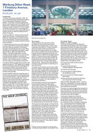
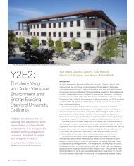
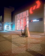
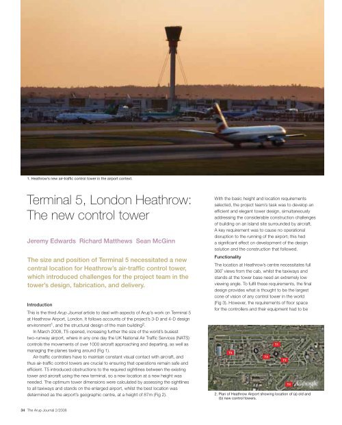
1. <strong>Heathrow</strong>’s <strong>new</strong> air-traffic <strong>control</strong> <strong>tower</strong> in the airport context.<br />
<strong>Terminal</strong> 5, <strong>London</strong> <strong>Heathrow</strong>:<br />
<strong>The</strong> <strong>new</strong> <strong>control</strong> <strong>tower</strong><br />
Jeremy Edwards Richard Matthews Sean McGinn<br />
<strong>The</strong> size and position of <strong>Terminal</strong> 5 necessitated a <strong>new</strong><br />
central location for <strong>Heathrow</strong>’s air-traffic <strong>control</strong> <strong>tower</strong>,<br />
which introduced challenges for the project team in the<br />
<strong>tower</strong>’s design, fabrication, and delivery.<br />
Introduction<br />
This is the third <strong>Arup</strong> Journal article to deal with aspects of <strong>Arup</strong>’s work on <strong>Terminal</strong> 5<br />
at <strong>Heathrow</strong> Airport, <strong>London</strong>. It follows accounts of the project’s 3-D and 4-D design<br />
environment1 , and the structural design of the main building2 .<br />
In March 2008, T5 opened, increasing further the size of the world’s busiest<br />
two-runway airport, where in any one day the UK National Air Traffic Services (NATS)<br />
<strong>control</strong>s the movements of over 1000 aircraft approaching and departing, as well as<br />
managing the planes taxiing around (Fig 1).<br />
Air-traffic <strong>control</strong>lers have to maintain constant visual contact with aircraft, and<br />
thus air-traffic <strong>control</strong> <strong>tower</strong>s are crucial to ensuring that operations remain safe and<br />
efficient. T5 introduced obstructions to the required sightlines between the existing<br />
<strong>tower</strong> and aircraft using the <strong>new</strong> terminal, so a <strong>new</strong> location at a <strong>new</strong> height was<br />
needed. <strong>The</strong> optimum <strong>tower</strong> dimensions were calculated by assessing the sightlines<br />
to all taxiways and stands on the enlarged airport, whilst the best location was<br />
determined as the airport’s geographic centre, at a height of 87m (Fig 2).<br />
34 <strong>The</strong> <strong>Arup</strong> Journal 2/2008<br />
With the basic height and location requirements<br />
selected, the project team’s task was to develop an<br />
efficient and elegant <strong>tower</strong> design, simultaneously<br />
addressing the considerable construction challenges<br />
of building on an island site surrounded by aircraft.<br />
A key requirement was to cause no operational<br />
disruption to the running of the airport; this had<br />
a significant effect on development of the design<br />
solution and the construction that followed.<br />
Functionality<br />
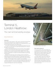
<strong>The</strong> location at <strong>Heathrow</strong>’s centre necessitates full<br />
360˚ views from the cab, whilst the taxiways and<br />
stands at the <strong>tower</strong> base need an extremely low<br />
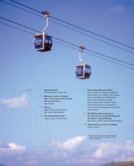
viewing angle. To fulfil these requirements, the final<br />
design provides what is thought to be the largest<br />
cone of vision of any <strong>control</strong> <strong>tower</strong> in the world<br />
(Fig 3). However, the requirements of floor space<br />
for the <strong>control</strong>lers and their equipment had to be<br />
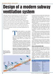
T5<br />
b<br />
T3<br />
2. Plan of <strong>Heathrow</strong> Airport showing location of (a) old and<br />
(b) <strong>new</strong> <strong>control</strong> <strong>tower</strong>s.<br />
T1<br />
a<br />
T2<br />
T4
alanced against the detrimental effects of increasing the size of the cab, which<br />
included reduced angles of vision for individual <strong>control</strong>lers, larger areas of glass, more<br />
solar gain, and wind drag on the <strong>tower</strong>. A great deal of detailed 3-D co-ordination<br />
between all design disciplines was needed to provide the most compact yet functional<br />
space possible (Fig 4).<br />
<strong>The</strong> cab contains four levels, the highest being the visual <strong>control</strong> room (VCR),<br />
accommodating desks for 13 <strong>control</strong>lers. This floor is set back from the 10m high<br />
glass façade. At the base of this wall is a gallery space used to service the subequipment<br />
room containing communications and radar equipment. Underneath the<br />
sub-equipment level is the rest and recreation area containing a rest room, kitchen,<br />
toilet, and office. An external walkway here accesses a permanent cleaning cradle to<br />
service the entire cab glass wall.<br />
<strong>The</strong> lowest level accommodates the air-handling plant as well as docking for the<br />
lift that travels up the outside of the mast. <strong>The</strong> mast structure itself contains stairs, an<br />
internal lift, and various risers for M&E and IT purposes. This rises through the middle<br />
of the cab and services every level.<br />
Finally, a three-storey building at the base of the <strong>tower</strong> contains the NATS offices,<br />
administration and training rooms, technical equipment areas, and main plantrooms.<br />
Construction method<br />
Importantly, the construction strategy was developed in parallel with the design.<br />
A key aspect of the project was the use of the T5 agreement, the form of collaboration<br />
contract used by BAA when appointing its design consultants and contractors.<br />
This allowed the <strong>tower</strong> design to be specifically tailored to suit the erection strategy,<br />
with designers and construction team working together from the outset.<br />
<strong>The</strong> design team considered using a traditional slip-formed concrete cantilever<br />
mast, but this would have required regular and uninterrupted concrete deliveries.<br />
Security, operations, and radar restrictions applying in the airport would also have<br />
necessitated an on-site batching plant, with cranes only usable in five-hour nighttime<br />
airport closures. In view of this, the team decided on a cable-stayed steel <strong>tower</strong>,<br />
which could have half the mast diameter of an equivalent cantilevered mast structure.<br />
A steel <strong>tower</strong> could also be prefabricated and transported to site in 12m lengths,<br />
completely fitted out with stairs, lift cores, and mechanical-and-electrical risers,<br />
and then bolted together.<br />
In addition, a small-diameter cable-stayed mast satisfied concerns about the visual<br />
impact of a traditional large-diameter concrete cantilever <strong>tower</strong> on the <strong>Heathrow</strong><br />
skyline, as well as making it possible to construct the cab at ground level around the<br />
base of the mast, and later jack it up into position at the top. Building the cab at low<br />
level had several safety advantages, though significant challenges were also involved<br />
in making it structurally stable with the large hole through the middle for the mast.<br />
<strong>The</strong>se were met by using an idea from the petrochemical industry for erecting<br />
process plant (Fig 5). Its great advantage is that is allows the complete cab to be<br />
built at ground level without incorporating a temporary hole for jacking the cab up<br />
the mast. Understanding the prefabrication, transportation, and erection requirements<br />
was essential in defining the parameters to <strong>control</strong> the maximum diameter of the mast<br />
and the design requirements for the cab structure.<br />
Dynamic performance<br />
Alongside the erection strategy, another factor critical to the structural requirements<br />
for the mast was wind-induced movement of the completed <strong>tower</strong>.<br />
Setting appropriate “comfort” criteria for tall buildings is more difficult than<br />
most design cases faced by engineers; here the <strong>tower</strong>’s dynamic performance<br />
was critical to the comfort of the air-traffic <strong>control</strong>lers. In the case of wind-induced<br />
lateral movements, acceptable performance is both time-dependent and varies with<br />
occupier sensitivity. <strong>The</strong> more often movement occurs, the less tolerant are occupiers<br />
of the level of lateral acceleration they experience. In the case of <strong>Heathrow</strong>, which<br />
often experiences fairly windy conditions, the frequent lower-strength winds formed<br />
the critical design case.<br />
3. <strong>The</strong> 10m high glass façade provides a large cone of vision.<br />
4. Section through <strong>control</strong> <strong>tower</strong> cab.<br />
Visual<br />
<strong>control</strong><br />
room<br />
Gallery<br />
Rest and<br />
recreation<br />
Plant<br />
5. Tower jacking: three temporary works <strong>tower</strong>s support<br />
strand-jacks and yoke system; the strands lift the yoke<br />
and mast off the ground via hydraulic jaws to allow a <strong>new</strong><br />
section of mast to be inserted underneath.<br />
<strong>The</strong> <strong>Arup</strong> Journal 2/2008 35
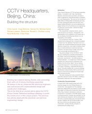
6. Cab model in<br />
wind tunnel.<br />
a)<br />
b)<br />
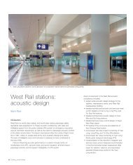
7. Airflow around 1:30<br />
mast model in a<br />
wind-tunnel smoke<br />
stream without<br />
(a) and with (b)<br />
aerodynamic strokes.<br />
36 <strong>The</strong> <strong>Arup</strong> Journal 2/2008<br />
During the early design stages, various levels of<br />
lateral acceleration were demonstrated to the<br />
air-traffic <strong>control</strong>lers on a motion simulator at<br />
Southampton University, and levels of acceptable<br />
movement of the <strong>control</strong> room were agreed.<br />
With these performance limits established, the<br />
design then focused on the <strong>tower</strong>’s aerodynamic<br />
performance, stiffness, and damping.<br />
Wind-tunnel testing<br />
Extensive wind-tunnel modelling (Fig 6) was<br />
undertaken to optimise the <strong>tower</strong>’s aerodynamic<br />
performance by reducing the drag and crosswind<br />
response of the design. <strong>The</strong>se tests were used to<br />
develop a unique aerodynamically sculpted enclosure<br />
for the support rails and drive cables of the external<br />
passenger lift, reducing both the drag on the <strong>tower</strong><br />
and improving the high-wind operation of the lift.<br />
Small aerodynamic strakes (stabilisers) were<br />
also developed in the wind tunnel. Attached to the<br />
side of the mast, these <strong>control</strong> vortex-shedding and<br />
significantly reduce the cross-wind response (Fig 7).<br />
Mast stiffness and damping<br />
<strong>The</strong> <strong>tower</strong>’s lateral stiffness and mass define its<br />
natural frequency. <strong>The</strong> amount of wind energy<br />
available to cause motion, and the sensitivity of the<br />
<strong>tower</strong> occupants, are both frequency-dependent.<br />
In developing the <strong>Heathrow</strong> <strong>tower</strong> design, the<br />
diameter, type, geometry, and pre-tension of the<br />
main stay cables was critical to its final performance.<br />
<strong>The</strong> 150mm diameter locked coil cables, stressed<br />
to a 10th of their normal working capacity, give the<br />
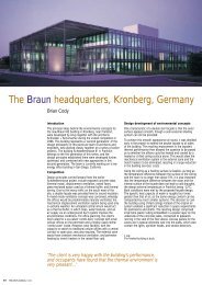
8. Prefabricated mast section before installation of stairs and lift risers.<br />
axial stiffness needed to <strong>control</strong> the head of the mast<br />
and also provide considerable reserves of strength,<br />
allowing the <strong>tower</strong> to operate safely if cables ever<br />
need to be removed for replacement. <strong>The</strong> cable<br />
natural frequencies are governed by the cable<br />
mass, axial stiffness, and the degree of pre-tension.<br />
Coincidentally, the optimum pre-tension for overall<br />
<strong>tower</strong> stiffness resulted in cable natural frequencies<br />
very close to those of the <strong>tower</strong> system as a whole.<br />
De-tuning the cable pre-tension would have resulted<br />
in a much less efficient structure.<br />
<strong>The</strong> final engineering factor that determines the<br />
<strong>tower</strong>’s dynamic performance is its damping.<br />
<strong>The</strong> natural damping of the steel mast and cables is<br />
low (0.5%), so small viscous dampers were attached<br />
to the main cables to damp their lateral vibration,<br />
to prevent unpredictable and un<strong>control</strong>lable transfer<br />
of energy between the cables and <strong>tower</strong> dynamic<br />
modes, and to and lift the overall <strong>tower</strong> damping<br />
to 1.5%.<br />
Finally, two hybrid mass dampers (Fig 12) were<br />
installed at the head of the mast immediately below<br />
the <strong>control</strong> room floor. <strong>The</strong>se have both passive and<br />
active operational modes. In normal higher-wind<br />
situations, accelerometers in the cab detect <strong>tower</strong><br />
movement and the <strong>control</strong> system then activates the<br />
dampers, moving the 5 tonne suspended masses in<br />
the appropriate direction to counteract the winddriven<br />
<strong>tower</strong> movement. <strong>The</strong>se raise the overall<br />
damping of the <strong>tower</strong> to levels in excess of 10%<br />
critical damping. <strong>Arup</strong> was instrumental in developing<br />
the design and validation of both the passive and the<br />
active damping systems.
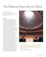
9. Mast stress diagrams.<br />
a) Temporary erection stresses<br />
-200MPa<br />
-100<br />
-50<br />
0<br />
50<br />
b) Permanent<br />
mast stresses<br />
0.01MPa<br />
26.12<br />
52.23<br />
78.34<br />
104.44<br />
130.55<br />
156.66<br />
Structural design<br />
<strong>The</strong> steel mast was built in eight sections, normally<br />
12m in length, with a 30mm thick outer steel skin,<br />
vertical longitudinal stiffeners, and horizontal stiffener<br />
hoops. <strong>The</strong> stresses induced in the steel mast during<br />
the temporary jacking cycles (Fig 9a) were very<br />
different from those it experiences in its permanent<br />
erected state (Fig 9b), and so it was designed to<br />
resist these considerable stresses during erection.<br />
Apart from the obvious compression loads carried<br />
by the mast, the critical additional design loads were<br />
generated by concentrated load from the lifting jaws<br />
during erection and by locked-in thermal stresses in<br />
the permanent state.<br />
<strong>The</strong> high axial stiffness of the cable stays generate<br />
unusually high thermal stresses, as they restrict the<br />
<strong>tower</strong>’s natural tendency to sway sideways under<br />
differential solar-induced thermal expansion on one<br />
side of the mast. A grey glass-flake epoxy paint, with<br />
low solar absorption, was used to limit the locked-in<br />
thermal stresses in the mast.<br />
<strong>The</strong>rmal-stress modelling by <strong>Arup</strong> also showed<br />
that even a small air velocity makes a big difference<br />
to the steel temperature gradient around the mast.<br />
Back-analysis of UK Meteorological Office data<br />
showed that, even on the hottest days, there is<br />
always a small amount of background wind, and this<br />
was duly added to the thermal model.<br />
To maximise usable floor space, the cab has<br />
no internal columns. Radial trusses in the roof act<br />
with each of the 24 façade mullions to form a 3-D<br />
portal frame. Floors within the cab span between<br />
the perimeter mullions and the steel mast. At the<br />
lowest cab level, structural loads in the mullions are<br />
transferred to the red-coloured structural steel skin<br />
spanning between the three support points offered<br />
by the main cable anchorages (Fig 11).<br />
Construction co-ordination<br />
One construction issue remained: prefabrication of the cab structure at ground level<br />
would require cranage. This would limit construction to night time only as cranage<br />
limitations were in force during airport operations. However, it was realised that as<br />
the cab structure was designed to be lifted by strand jacks attached to three points<br />
on the temporary works jacking frame, the same points could be used to lift and<br />
transport the cab from a remote site using multi-wheeled transporter units able to lift<br />
and transport large loads, as is the case in the petrochemical industry.<br />
<strong>The</strong> client, BAA, identified a suitable open site near <strong>Terminal</strong> 4 that would enable cab<br />
construction and fit-out to start early and progress in parallel with installation of the<br />
main foundations on the <strong>control</strong> <strong>tower</strong> site. <strong>The</strong>se foundations comprise 1050mm<br />
and 750mm diameter piles, and pile caps up to 4.1m deep that support the <strong>tower</strong>,<br />
the base building, and permanent guy cables. <strong>The</strong> site had to be cleared in order to<br />
construct the main foundations.<br />
Mast fabrication<br />
As site work progressed, the first 12m long mast sections were fabricated. To achieve<br />
satisfactory alignment and force transfer between adjacent mast sections, careful<br />
<strong>control</strong> of tolerances in each was required.<br />
<strong>The</strong> initial fabrication method used on the two top mast sections did not give<br />
adequate steel tolerances, but fortunately they could still be used because the<br />
compressive forces at the top of the <strong>tower</strong> are low, and the lower tolerances<br />
11. Cross-section through top of <strong>tower</strong>.<br />
Gallery<br />
Office<br />
Tuned mass<br />
dampers<br />
Services<br />
void<br />
Lift lobby<br />
M&E plantroom<br />
Visual<br />
<strong>control</strong><br />
room<br />
High level<br />
service void<br />
Sub-engineer’s<br />
room<br />
Rest and<br />
recreation<br />
area<br />
External<br />
maintenance<br />
gallery<br />
12. A 5 tonne active<br />
mass damper<br />
located at cab level.<br />
<strong>The</strong> <strong>Arup</strong> Journal 2/2008 37
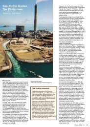
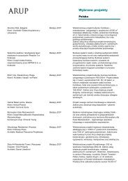
12. Erecting the two top<br />
mast sections for<br />
cab construction.<br />
13. Locating cab roof<br />
onto 24 mullions.<br />
14. Moving 900 tonnes<br />
1.5km across<br />
the airport.<br />
15. Jacking the cab to<br />
87m height.<br />
38 <strong>The</strong> <strong>Arup</strong> Journal 2/2008<br />
were acceptable. In the revised procedure, precision<br />
jigs were used to fabricate 3m long sections of mast<br />
tube, which were heavily braced during fabrication to<br />
<strong>control</strong> weld shrinkage effects. Before removal of the<br />
bracing, the sections were heat-treated to stressrelieve<br />
them and ensure that fabrication accuracy<br />
was maintained. <strong>The</strong> 3m sections were then stacked<br />
and welded into the final 12m lengths. Prior to<br />
painting, the bolted interface flanges at the ends of<br />
the mast sections were milled and CNC (computer<br />
numerically <strong>control</strong>led) drilled to ensure precise fit and<br />
alignment on site. Before transport to site, the mast<br />
sections were fitted out with the steel stairs, service<br />
risers, and the lift enclosure.<br />
Cab construction<br />
Cab construction on the remote site began with<br />
a temporary piled foundation, off which the 32m<br />
high cab was built. <strong>The</strong> top two sections of mast<br />
were used as a core from which all the floors were<br />
suspended (Fig 12). <strong>The</strong> main cable anchorages,<br />
stressed steel skin, and structural mullion systems<br />
were added to create a coronet of 24 mullions to<br />
which the roof would connect.<br />
<strong>The</strong> roof structure, complete with internal acoustic<br />
lining, access walkway, decking, and waterproofing<br />
was constructed at ground level. <strong>The</strong> entire 50 tonne<br />
roof was craned into place (Fig 13) and connected<br />
to the ring of mullions. Before being moved from the<br />
temporary site, the cab was fully fitted out with M&E<br />
plant, walls, and ceilings.<br />
Moving the cab<br />
Preplanning the cab’s 1.5km journey across the<br />
airport took considerable effort. <strong>The</strong> route crossed<br />
over the southern runway and involved using the<br />
main taxiways to get to the final site. <strong>The</strong> entire route<br />
had to be meticulously assessed for its load-carrying<br />
capacity because at close to 900 tonnes, the<br />
transported load greatly exceeded the 400 tonnes<br />
of a fully-loaded Boeing 747 for which the pavement<br />
was designed. Damage to the runway or breakdown<br />
of the transporter en route could cause effective<br />
closure of the airport - with resultant damages likely<br />
to exceed half the value of the entire <strong>control</strong> <strong>tower</strong><br />
project. Detailed contingency plans were put in place<br />
to cover all eventualities.<br />
After a 24-hour delay due to thunderstorms,<br />
the overnight move (Fig 14) was achieved without<br />
incident in less than two hours amidst a sea of press<br />
and TV cameras. At the <strong>control</strong> <strong>tower</strong> site, the 32m<br />
high, 750 tonne cab was manoeuvred and placed<br />
onto its foundation to within 10mm of dead centre.<br />
Mast erection<br />
Once the cab was successfully moved, the mast<br />
jacking <strong>tower</strong>s were installed and the first of five<br />
mast lifts commenced, each mast section being<br />
successively added to the underside of the <strong>tower</strong><br />
(Fig 15). Software developed by the jacking<br />
contractor was used to ensure that the lift was<br />
always level by <strong>control</strong>ling the strand jacks and guy<br />
cables. Prior to its use on site, the <strong>control</strong> logic of this<br />
custom-written jacking software had been tested and<br />
refined using a small-scale test rig.<br />
To ensure verticality of the <strong>tower</strong> during the lift,<br />
both optical and GPS surveying were used to monitor<br />
the plumb of the mast. In general the top of the <strong>tower</strong><br />
was maintained within 25mm of plumb throughout<br />
erection (Fig 16).<br />
During the jacking cycles a procedure linking<br />
regional weather forecasting and local wind<br />
measurement was put into place to predict and<br />
monitor the weather conditions during each lift.<br />
<strong>The</strong> erection procedure had various wind limits<br />
placed on it but in the case of the most severe<br />
predicted weather, the <strong>tower</strong> was to be lowered<br />
onto its foundation and supported on multiple<br />
interconnected jacks forming a hydraulic pin at the<br />
base. In this situation, a second set of guy cables<br />
(Fig 5) were to be tensioned to give the mast<br />
additional strength and stiffness. Fortunately no<br />
weather severe enough to need these precautions<br />
was experienced. As well as eliminating non-uniform<br />
compression stresses in the mast, the hydraulic<br />
pin also served as a damper to absorb energy from<br />
wind-induced oscillations and remove the risk of<br />
aerodynamic instability during all stages of erection.<br />
As the lifts progressed, a cycle of mast jacking<br />
during the day was followed by preparation of the<br />
next mast section during a night shift. Although<br />
the rig could raise the mast to the required height<br />
for each lift in a day, the process demanded so<br />
much preparation that it took about three weeks<br />
in all. However, all five mast lifts were completed<br />
without incident while airport operations continued<br />
uninterrupted around the site (Fig 17).<br />
Completion<br />
With mast erection complete, the project immediately<br />
progressed to the erection and fit-out of the base<br />
building and the connection of services between it<br />
and the cab. Once this was complete, the temporary<br />
guy cables were removed and the permanent<br />
150mm diameter locked coil cables installed from<br />
a crane and tensioned during a further series of<br />
night-time operations.<br />
<strong>The</strong> final installations and commissioning in the<br />
<strong>tower</strong> included tuning the hybrid mass dampers to<br />
suit the <strong>tower</strong>’s final as-built natural frequency.<br />
Also installed was a 100m pedestrian bridge link<br />
from the <strong>control</strong> <strong>tower</strong> base building to the end of<br />
<strong>Terminal</strong> 3’s Pier 7. Each section of the glazed bridge,<br />
designed by Thyssen, was prefabricated in 30m<br />
lengths, brought directly to the <strong>tower</strong> site, and rapidly<br />
craned into place during night time operations.
16. Jacks <strong>control</strong>ling guy cables during the lift.<br />
Conclusion<br />
<strong>The</strong> <strong>new</strong> <strong>tower</strong> went ”live” in February 2007 when full<br />
airport operations transferred and the old <strong>tower</strong> was<br />
closed after 52 years of service.<br />
Building a <strong>new</strong> air-traffic <strong>control</strong> <strong>tower</strong> in the<br />
centre of <strong>Heathrow</strong>’s airside operations involved<br />
unique construction and operational requirements<br />
that largely dictated its architectural and engineering<br />
form (a more detailed description of the project has<br />
been published elsewhere3 ). This <strong>tower</strong> satisfies<br />
the air-traffic <strong>control</strong>lers’ requirements, yet was<br />
constructed with no disruption to the airport’s<br />
daily operations and no accidents. Its successful<br />
completion demonstrates the value of T5’s integrated<br />
design and construction philosophy.<br />
17. Tower and base building under construction.<br />
Jeremy Edwards is an Associate of <strong>Arup</strong> with the Building <strong>London</strong> 4 group. He is a structural<br />
engineer and has had several roles on T5, including assistant structural engineer for the air-traffic<br />
<strong>control</strong> <strong>tower</strong>.<br />
Richard Matthews is a Director of <strong>Arup</strong> with the Building <strong>London</strong> 9 group. He leads the<br />
structural engineering team for T5, and acted as Project Leader for BAA on the air-traffic<br />
<strong>control</strong> <strong>tower</strong>.<br />
Sean McGinn is a Senior Associate of <strong>Arup</strong> with the Buildings Melbourne, Australia, group.<br />
He was lead structural engineer of the air-traffic <strong>control</strong> <strong>tower</strong>.<br />
Credits<br />
Client: BAA (building owner, airport operator, overall project manager) Building operator: NATS<br />
Architect: Richard Rogers Partnership Project manager, structural engineer (superstructures),<br />
acoustics, façade, wind and dynamics engineer: <strong>Arup</strong> - Andrew Allsop, Mike Banfi, Francesco<br />
Biancelli, Nick Boulter, Anita Bramfitt, Simon Cardwell, Jeremy Edwards, Rob Embury, Matteo<br />
Farina, Graham Gedge, James Hargreaves, Richard Henderson, Roger Howkins, Angus Low,<br />
Richard Matthews, Chris Murgatoyd, Daniel Powell, Sean McGinn, Nils Svensson, Ian Wilson,<br />
Peter Young, Andrea Zelco Engineer (substructure): Mott Macdonald Temporary works<br />
designer: Dorman Long Technology Infrastructure engineer: TPS M&E engineer: DSSR Cost<br />
manager: Turner & Townsend/EC Harris Construction integrator: Mace Steelwork supplier:<br />
Watson Steel Substructure contractor: Laing O’Rourke Jacking and cab transportation:<br />
Faggiolli M&E and infrastructure contractor: AMEC Façade supplier: Schmidlin Lift supplier:<br />
Schindler Fit-out supplier: Warings Logistics: Amalga Illustrations: 1-10, 12-17 BAA/HATCT<br />
project team; 11 Nigel Whale.<br />
References<br />
(1) BEARDWELL, G et al. <strong>Terminal</strong> 5, <strong>London</strong> <strong>Heathrow</strong>: 3-D and 4-D design in a single model<br />
environment. <strong>The</strong> <strong>Arup</strong> Journal, 41(1), pp3-8, 1/2006.<br />
(2) McKECHNIE, S. <strong>Terminal</strong> 5, <strong>London</strong> <strong>Heathrow</strong>: <strong>The</strong> main terminal building envelope.<br />
<strong>The</strong> <strong>Arup</strong> Journal, 41(2), pp36-43, 2/2006.<br />
(3) MATTHEWS, R. Creating <strong>Heathrow</strong>’s <strong>new</strong> eye in the sky. Civil Engineering, 161(2),<br />
pp66-76, May 2008.<br />
<strong>The</strong> <strong>Arup</strong> Journal 2/2008 39