VAV500 Multi-functional variable air volume controller, analogue ...
VAV500 Multi-functional variable air volume controller, analogue ...
VAV500 Multi-functional variable air volume controller, analogue ...

You also want an ePaper? Increase the reach of your titles
YUMPU automatically turns print PDFs into web optimized ePapers that Google loves.
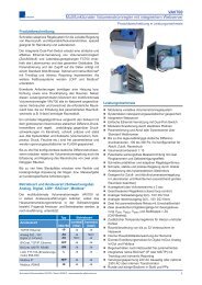
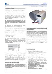
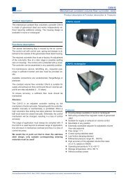
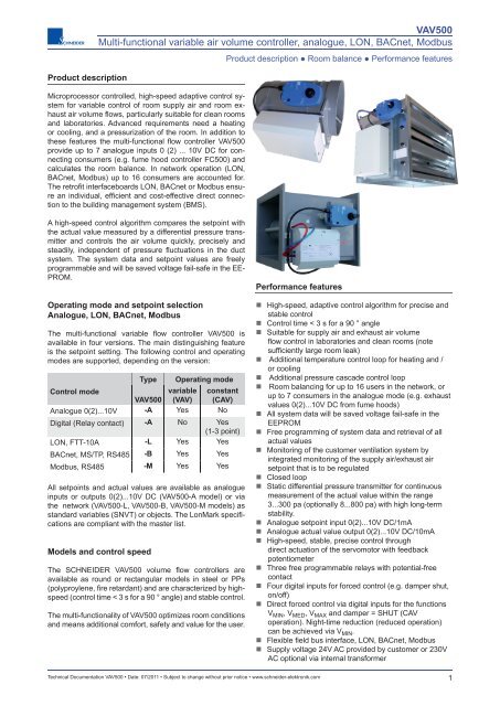
Product description<br />
<strong>VAV500</strong><br />
<strong>Multi</strong>-<strong>functional</strong> <strong>variable</strong> <strong>air</strong> <strong>volume</strong> <strong>controller</strong>, <strong>analogue</strong>, LON, BACnet, Modbus<br />
Microprocessor controlled, high-speed adaptive control system<br />
for <strong>variable</strong> control of room supply <strong>air</strong> and room exhaust<br />
<strong>air</strong> <strong>volume</strong> fl ows, particularly suitable for clean rooms<br />
and laboratories. Advanced requirements need a heating<br />
or cooling, and a pressurization of the room. In addition to<br />
these features the multi-<strong>functional</strong> fl ow <strong>controller</strong> <strong>VAV500</strong><br />
provide up to 7 <strong>analogue</strong> inputs 0 (2) ... 10V DC for connecting<br />
consumers (e.g. fume hood <strong>controller</strong> FC500) and<br />
calculates the room balance. In network operation (LON,<br />
BACnet, Modbus) up to 16 consumers are accounted for.<br />
The retrofi t interfaceboards LON, BACnet or Modbus ensure<br />
an individual, effi cient and cost-effective direct connection<br />
to the building management system (BMS).<br />
Product description ● Room balance ● Performance features<br />
A high-speed control algorithm compares the setpoint with<br />
the actual value measured by a differential pressure transmitter<br />
and controls the <strong>air</strong> <strong>volume</strong> quickly, precisely and<br />
steadily, independent of pressure fl uctuations in the duct<br />
system. The system data and setpoint values are freely<br />
programmable and will be saved voltage fail-safe in the EE-<br />
PROM.<br />
Operating mode and setpoint selection<br />
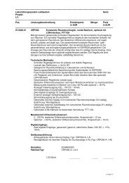
Analogue, LON, BACnet, Modbus<br />
The multi-<strong>functional</strong> <strong>variable</strong> fl ow <strong>controller</strong> <strong>VAV500</strong> is<br />
available in four versions. The main distinguishing feature<br />
is the setpoint setting. The following control and operating<br />
modes are supported, depending on the version:<br />
Type Operating mode<br />
Control mode<br />
<strong>variable</strong> constant<br />
<strong>VAV500</strong> (VAV) (CAV)<br />
Analogue 0(2)...10V -A Yes No<br />
Digital (Relay contact) -A No Yes<br />
(1-3 point)<br />
LON, FTT-10A -L Yes Yes<br />
BACnet, MS/TP, RS485 -B Yes Yes<br />
Modbus, RS485 -M Yes Yes<br />
All setpoints and actual values are available as <strong>analogue</strong><br />
inputs or outputs 0(2)...10V DC (<strong>VAV500</strong>-A model) or via<br />
the network (<strong>VAV500</strong>-L, <strong>VAV500</strong>-B, <strong>VAV500</strong>-M models) as<br />
standard <strong>variable</strong>s (SNVT) or objects. The LonMark specifi -<br />
cations are compliant with the master list.<br />
Models and control speed<br />
The SCHNEIDER <strong>VAV500</strong> <strong>volume</strong> fl ow <strong>controller</strong>s are<br />
available as round or rectangular models in steel or PPs<br />
(polyproylene, fi re retardant) and are characterized by highspeed<br />
(control time < 3 s for a 90 ° angle) and stable control.<br />
The multi-<strong>functional</strong>ity of <strong>VAV500</strong> optimizes room conditions<br />
and means additional comfort, safety and value for the user.<br />
Performance features<br />
• High-speed, adaptive control algorithm for precise and<br />
stable control<br />
• Control time < 3 s for a 90 ° angle<br />
• Suitable for supply <strong>air</strong> and exhaust <strong>air</strong> <strong>volume</strong><br />
fl ow control in laboratories and clean rooms (note<br />
suffi ciently large room leak)<br />
• Additional temperature control loop for heating and /<br />
or cooling<br />
• Additional pressure cascade control loop<br />
• Room balancing for up to 16 users in the network, or<br />
up to 7 consumers in the <strong>analogue</strong> mode (e.g. exhaust<br />
values 0(2)...10V DC from fume hoods)<br />
• All system data will be saved voltage fail-safe in the<br />
EEPROM<br />
• Free programming of system data and retrieval of all<br />
actual values<br />
• Monitoring of the customer ventilation system by<br />
integrated monitoring of the supply <strong>air</strong>/exhaust <strong>air</strong><br />
setpoint that is to be regulated<br />
• Closed loop<br />
• Static differential pressure transmitter for continuous<br />
measurement of the actual value within the range<br />
3...300 pa (optionally 8...800 pa) with high long-term<br />
stability.<br />
• Analogue setpoint input 0(2)...10V DC/1mA<br />
• Analogue actual value output 0(2)...10V DC/10mA<br />
• High-speed, stable, precise control through<br />
direct actuation of the servomotor with feedback<br />
potentiometer<br />
• Three free programmable relays with potential-free<br />
contact<br />
• Four digital inputs for forced control (e.g. damper shut,<br />
on/off)<br />
• Direct forced control via digital inputs for the functions<br />
V MIN , V MED , V MAX and damper = SHUT (CAV<br />
operation). Night-time reduction (reduced operation)<br />
can be achieved via V MIN .<br />
• Flexible field bus interface, LON, BACnet, Modbus<br />
• Supply voltage 24V AC provided by customer or 230V<br />
AC optional via internal transformer<br />
Technical Documentation <strong>VAV500</strong> • Date: 07/2011 • Subject to change without prior notice • www.schneider-elektronik.com<br />
1
<strong>VAV500</strong><br />
<strong>Multi</strong>-<strong>functional</strong> <strong>variable</strong> <strong>air</strong> <strong>volume</strong> <strong>controller</strong>, <strong>analogue</strong>, LON, BACnet, Modbus<br />
Functional description • Variable <strong>volume</strong> fl ow <strong>controller</strong> (<strong>VAV500</strong>), <strong>analogue</strong> setpoint control<br />
Volume flow measurement with a static differential<br />
pressure transmitter<br />
Using a suitable measuring device (maintenance-free measuring<br />
system, venturi measuring tube, orifi ce ring, measuring<br />
tube or measuring cross) the differential pressure is<br />
determined by a differential pressure transmitter. Measurement<br />
is very accurate and stable over the entire measuring<br />
range of 3...300 pa (optionally 8...800 pa), making it possible<br />
to regulate a <strong>volume</strong> fl ow range of 10:1.<br />
Unlike the thermo-anemometric measuring principle, <strong>air</strong><br />
does not fl ow through the static differential pressure transmitter,<br />
making it particularly suitable for measuring in dusty<br />
and contaminated (corrosive) media (its suitability should<br />
be checked in individual cases. The suitability of the thermo-anemometric<br />
measuring principle for such media is very<br />
limited, as the sensor becomes dirty or is affected by corrosive<br />
<strong>air</strong> and thus measurement may be very imprecise or<br />
inaccurate.<br />
Volume flow settings V MIN , V MED , V MAX<br />
Setting of the <strong>volume</strong> fl ow (programming) is done via the<br />
service module SVM100 or the Laptop (with software<br />
PC2500). The desired <strong>volume</strong> fl ow is entered as a numeric<br />
value in m 3 /h.<br />
Function Volume flow Demand signal w<br />
V MIN minimum 0(2) ≤ w ≤ 10V DC<br />
V MED median value 0(2) ≤ w ≤ 10V DC<br />
V MIN ≤ V MED ≤ V MAX<br />
V MAX maximum w = 10V DC<br />
The allocation of the <strong>analogue</strong> demand signal w to the <strong>volume</strong><br />
fl ow V MIN and V MAX accentuates the VAV curve (<strong>variable</strong><br />
operating mode).<br />
The <strong>volume</strong> fl ow value V MED is only available in constant<br />
operating mode (see CAV curve) and is digitally controlled<br />
(e.g. via relay contacts). V MED must always lie between<br />
V MIN and V MAX .<br />
Demand signal w (setpoint setting via<br />
<strong>analogue</strong> input A8-In)<br />
With the demand signal w (setpoint selection), the <strong>volume</strong><br />
fl ow can be constantly switched between V MIN and V MAX , at<br />
which the following is always true:<br />
0m 3 /h = 0(2)V DC, V MAX = 10V DC<br />
The regulated <strong>volume</strong> fl ow actual value (A2-Out) is available<br />
as 0(2)...10V DC output voltage. Various master/slave<br />
operating modes can be implemented with this signal.<br />
Shield factor (C value)<br />
The shield factor is the geometry-dependent constant of the<br />
measuring device used (construction of the damming body<br />
and geometric dimensions).<br />
The <strong>volume</strong> fl ow is calculated according to the following<br />
formula:<br />
Function Meaning Notes<br />
V MIN<br />
.<br />
V MAX<br />
Shield<br />
factor<br />
Type<br />
default<br />
V MED<br />
Offset<br />
V = c .<br />
p<br />
Programming of the <strong>volume</strong> flow <strong>controller</strong><br />
Using the service module SVM100 or the Laptop the <strong>volume</strong><br />
fl ow <strong>controller</strong> is programmed as follows:<br />
minimum <strong>volume</strong><br />
fl ow<br />
maximum <strong>volume</strong><br />
fl ow<br />
measuring device<br />
constant<br />
<strong>controller</strong><br />
confi guration<br />
interim value<br />
V MIN ≤ V MED ≤ V MAX<br />
fi xed +/- value for<br />
constant loads<br />
shield factor<br />
S * 1,5 (rule of thumb)<br />
shield factor<br />
S * 16 (rule of thumb)<br />
10...2000<br />
<strong>analogue</strong> (VAV)<br />
digital (CAV)<br />
digital operating mode<br />
only (CAV)<br />
+9990 m 3 /h to<br />
- 9990 m 3 /h<br />
Type default (setpoint value = <strong>analogue</strong> or digital)<br />
The <strong>controller</strong> configuration specifi es the operating mode<br />
(<strong>analogue</strong> or digital).<br />
In <strong>analogue</strong> operating mode (<strong>variable</strong> <strong>volume</strong> fl ow <strong>controller</strong><br />
= VAV) the <strong>volume</strong> fl ow is regulated linearly based on<br />
the <strong>analogue</strong> demand signal w (setpoint value via <strong>analogue</strong><br />
input A8-In).<br />
In digital operating mode (constant <strong>volume</strong> fl ow <strong>controller</strong> =<br />
CAV) the <strong>volume</strong> fl ow is regulated in stages based on the<br />
digital inputs (In2, In3 and In4). Up to four different <strong>volume</strong><br />
fl ows (V MIN , V MED and V MAX and V EMERGENCY ) can be regulated.<br />
An <strong>analogue</strong> demand signal is not required.<br />
In both operating modes (VAV and CAV) pressure fl uctations<br />
in the duct system are recognized and automatically<br />
regulated.<br />
Offset for integrating constant loads<br />
.<br />
V = <strong>air</strong> <strong>volume</strong><br />
c = geometrical constant<br />
(shield factor)<br />
p = differential pressure<br />
= <strong>air</strong> density<br />
With the offset value a fi xed value is programmed (+9990<br />
to - 9990 m3/h) that is added to the <strong>volume</strong> fl ow setpoint (+<br />
offset = increases the <strong>volume</strong> fl ow setpoint, - offset decreases<br />
the <strong>volume</strong> fl ow setpoint). This makes it possible to<br />
integrate constant loads.<br />
A constant difference between supply and exhaust <strong>air</strong> is<br />
therefore possible in master/slave mode. This function is<br />
particularly important in <strong>air</strong>tight rooms (e.g. clean rooms).<br />
2 Technical Documentation <strong>VAV500</strong> • Date: 07/2011 • Subject to change without prior notice • www.schneider-elektronik.com
<strong>VAV500</strong><br />
<strong>Multi</strong>-<strong>functional</strong> <strong>variable</strong> <strong>air</strong> <strong>volume</strong> <strong>controller</strong>, <strong>analogue</strong>, LON, BACnet, Modbus<br />
Operating modes • Variable <strong>volume</strong> flow <strong>controller</strong> (VAV) • Constant <strong>volume</strong> flow <strong>controller</strong> (CAV)<br />
Notes on <strong>controller</strong> dimensioning (dimensions and <strong>volume</strong><br />
flow)<br />
0 = contact open (no current)<br />
1 = contact closed (under current)<br />
Due to measurement accuracy it must be ensured that at<br />
the minimum <strong>volume</strong> fl ow V MIN the fl ow velocity in the <strong>volume</strong><br />
fl ow <strong>controller</strong> does not fall below 2 m/s.<br />
Due to noise development, in laboratory applications it must<br />
be ensured that at the maximum <strong>volume</strong> fl ow V MAX the fl ow<br />
velocity in the <strong>volume</strong> fl ow <strong>controller</strong> does not exceed 7,5<br />
m/s.<br />
The <strong>volume</strong> fl ows V MIN , V MED , V MAX are freely programmable<br />
within the range 50...25.000 m 3 /h, but care must be<br />
taken to ensure suitable <strong>volume</strong> fl ow <strong>controller</strong> dimensions<br />
with regard to the <strong>volume</strong> fl ow range while at the same time<br />
taking the fl ow velocity into account.<br />
See the terminal diagram on page 23 for wiring information.<br />
Determination <strong>volume</strong> flow for laboratory applicationstaking<br />
the flow velocity v into account<br />
Volume flow<br />
Flow velocity v<br />
V MIN v ≥ 2 m/s<br />
V MAX v ≤ 7,5 m/s<br />
Analogue operating mode<br />
Variable <strong>volume</strong> flow <strong>controller</strong> (VAV)<br />
Diagram 1: <strong>variable</strong> <strong>volume</strong> flow control (VAV)<br />
[V]<br />
V MAX<br />
10<br />
[V]<br />
10<br />
In <strong>variable</strong> <strong>volume</strong> fl ow operating mode the desired <strong>volume</strong><br />
fl ow is predefi ned by a demand signal w (setpoint setting).<br />
The value range of the demand signal is 0(2)...10V DC.<br />
The <strong>volume</strong> fl ow can be constantly controlled between V MIN<br />
und V MAX with the demand signal w, at which the following<br />
is always true:<br />
Leading signal w (A-In1)<br />
9<br />
8<br />
7<br />
6<br />
5<br />
4<br />
3<br />
2<br />
V MIN<br />
9<br />
8<br />
7<br />
6<br />
5<br />
4<br />
3<br />
2<br />
Air <strong>volume</strong> actual value (A-Out1)<br />
0m 3 /h = 0(2)V DC<br />
0(2) ≤ V MIN ≤ 10V DC<br />
V MAX = 10V DC<br />
1<br />
0<br />
0 200 400 600 800 1000 [m 3 /h]<br />
1<br />
0<br />
Always note:<br />
1. Minimum control value VMIN = shield factor B * 1.5<br />
2. Values
<strong>VAV500</strong><br />
<strong>Multi</strong>-<strong>functional</strong> <strong>variable</strong> <strong>air</strong> <strong>volume</strong> <strong>controller</strong>, <strong>analogue</strong>, LON, BACnet, Modbus<br />
Master / slave sequence control • Equal percentage ratio • Constant difference<br />
Digital operating mode<br />
Constant <strong>volume</strong> flow <strong>controller</strong> (CAV)<br />
In constant <strong>volume</strong> fl ow operating mode (digital operating<br />
mode) the desired <strong>volume</strong> fl ow is controlled based on the<br />
digital inputs.<br />
The available operating stages are shown in diagram 2 and<br />
Table 2. 1 point, 2 point, 3 point or 4 point operation can<br />
easily be implemented by direct control of the digital inputs.<br />
The <strong>volume</strong> fl ows are programmed to the values V MIN = 875<br />
m 3 /h, V MED = 1750 m 3 /h and V MAX = 2150 m 3 /h. V MED must<br />
always lie between V MIN and V MAX . The <strong>volume</strong> fl ow actual<br />
value signal (A2--Out) correlates with the regulated <strong>volume</strong><br />
fl ow.<br />
The following is valid for the <strong>volume</strong> fl ow actual value:<br />
SHUT = 0m 3 /h = 0(2)V DC<br />
0(2) ≤ V MIN ≤ 10V DC<br />
V MIN ≤ V MED ≤ V MAX<br />
V MAX = 10V DC<br />
See above and the terminal diagram on page 23 for information<br />
on the digital input wiring.<br />
Master-slave sequence control with equal<br />
percentage ratio in VAV operation<br />
This master-slave sequence control is always used when<br />
room pressure must be maintained at an equal percentage<br />
ratio of supply and exhaust <strong>air</strong>. Suffi cient replacement fl ow<br />
of the difference between the supply and exhaust <strong>air</strong> must<br />
be ensured in this operating mode.<br />
The master <strong>controller</strong> is programmed with the <strong>volume</strong> fl ow<br />
values V MIN and V MAX and the demand signal w is added<br />
on directly. The <strong>volume</strong> fl ow actual value of the master <strong>controller</strong><br />
provides the demand signal for the slave <strong>controller</strong>,<br />
which can be programmed with other V MIN and V MAX <strong>volume</strong><br />
fl ow values depending on the application.<br />
If the master <strong>controller</strong> is mounted in the supply <strong>air</strong> and<br />
the slave <strong>controller</strong> in the exhaust <strong>air</strong> and positive (+) room<br />
pressure is required, the slave <strong>controller</strong> must be programmed<br />
with the lower percentage <strong>volume</strong> fl ow values V MIN<br />
and V MAX in relation to the master <strong>controller</strong>.<br />
If negative (-) room pressure is required, the slave <strong>controller</strong><br />
must be programmed with the lower percentage <strong>volume</strong><br />
fl ow values V MIN and V MAX in relation to the master <strong>controller</strong>.<br />
Sample settings for master/slave <strong>controller</strong>s:<br />
Slave (+) Master Slave(-)<br />
V MIN 240 300 360<br />
V MAX 600 750 900<br />
Diagram 2: Constant <strong>volume</strong> flow control (CAV)<br />
Function Input 1 Input 2<br />
V MAX 0 0<br />
V MED 1 1<br />
V MIN 1 0<br />
SHUT 0 1<br />
Table 2:<br />
Digital inputs<br />
Funktion In 2 In 3 In4<br />
V MAX 0 0 0<br />
V MIN 1 0 0<br />
V MED 0 1 0<br />
V EMERGENCY or damper SHUT 0 0 1<br />
Contact open = 0, contact closed = 1.<br />
The digital input In1 is the highest priority and switches the<br />
fl ow <strong>controller</strong> <strong>VAV500</strong> ON or OFF.<br />
Schematic diagram: Master-slave sequence control<br />
in VAV operation<br />
Room supply<br />
VAV<br />
dp M<br />
<strong>VAV500</strong><br />
Master<br />
Leading signal w<br />
SHUT<br />
Air <strong>volume</strong> actual value<br />
0 500 1000 1500 2000 2500 [m 3 /h]<br />
Damper position<br />
SHUT<br />
V MIN<br />
V MIN<br />
Forced control VAV operation in<br />
digital operating mode (CAV)<br />
T<br />
Room exhaust<br />
VAV<br />
V MED<br />
V MED<br />
dp M<br />
<strong>VAV500</strong><br />
Slave<br />
V MAX<br />
V MAX<br />
Air <strong>volume</strong><br />
actual value<br />
Air <strong>volume</strong><br />
Building Management<br />
System<br />
System network<br />
DDC<br />
substation<br />
The master slave sequence control applies for both equal<br />
percentage ratio and constant difference between supply<br />
and exhaust <strong>air</strong>. The demand signal w (A8-In) is added on<br />
to the master <strong>controller</strong> and the <strong>volume</strong> fl ow actual value<br />
(A2-Out) provides the demand signal for the slave <strong>controller</strong>.<br />
This ensures that the slave <strong>controller</strong> always follows the<br />
master <strong>controller</strong>. For safety reasons, master/slave sequence<br />
control must always be given preference over parallel<br />
control.<br />
[V]<br />
10<br />
9<br />
8<br />
7<br />
6<br />
5<br />
4<br />
3<br />
2<br />
1<br />
0<br />
Air <strong>volume</strong> actual value (A-Out1)<br />
4 Technical Documentation <strong>VAV500</strong> • Date: 07/2011 • Subject to change without prior notice • www.schneider-elektronik.com
<strong>VAV500</strong><br />
<strong>Multi</strong>-<strong>functional</strong> <strong>variable</strong> <strong>air</strong> <strong>volume</strong> <strong>controller</strong>, <strong>analogue</strong>, LON, BACnet, Modbus<br />
In the sample settings, the <strong>volume</strong> fl ow values VMIN und<br />
VMAX of the slave (+) <strong>controller</strong> were programmed to -20%<br />
(negative room pressure) in relation to the <strong>volume</strong> fl ow values<br />
of the master <strong>controller</strong>. For negative room pressure<br />
the <strong>volume</strong> fl ow values V MIN and V MAX of the slave (-) <strong>controller</strong><br />
must be programmed to +20% in relation to the <strong>volume</strong><br />
fl ow values of the master <strong>controller</strong>.<br />
The equal percentage ratio between supply and exhaust <strong>air</strong><br />
is maintained throughout the entire <strong>volume</strong> fl ow range of<br />
V MIN to V MAX .<br />
Master / slave sequence control • Application examples<br />
Diagram 3: Sequence control (master/slave) in<br />
equal percentage ratio<br />
Leading signal w (A-In1)<br />
[V]<br />
10<br />
9<br />
8<br />
7<br />
6<br />
5<br />
4<br />
3<br />
2<br />
[V]<br />
10<br />
9<br />
8<br />
7<br />
6<br />
5<br />
4<br />
3<br />
2<br />
Air <strong>volume</strong> actual value (A-Out1)<br />
V MIN<br />
V MAX<br />
V MAX<br />
Master/slave sequence control with constant<br />
difference in VAV operating mode<br />
1<br />
0<br />
1<br />
0<br />
This form of master/slave sequence control is used when<br />
room pressure with a constant difference between supply<br />
and exhaust <strong>air</strong> is required. This operating mode is selected<br />
for <strong>air</strong>tight rooms (e.g. clean rooms).<br />
The master <strong>controller</strong> is programmed with the <strong>volume</strong> fl ow<br />
values V MIN and V MAX and the demand signal w is added<br />
on directly. The <strong>volume</strong> fl ow actual value of the master <strong>controller</strong><br />
provides the demand signal for the slave <strong>controller</strong>,<br />
which is programmed with the same <strong>volume</strong> fl ow values<br />
V MIN and V MAX , depending on the application.<br />
In addition, the offset is also programmed in the slave <strong>controller</strong>.<br />
If the master <strong>controller</strong> is mounted in the supply <strong>air</strong><br />
and the slave <strong>controller</strong> in the exhaust <strong>air</strong> and positive (+)<br />
room pressure is required, the slave <strong>controller</strong> must be programmed<br />
with a negative offset.<br />
[V]<br />
10<br />
9<br />
8<br />
7<br />
6<br />
5<br />
4<br />
0 200 400 600 800 1000 [m 3 /h]<br />
V MIN<br />
V MIN<br />
V MIN<br />
V MAX<br />
V MAX<br />
Air <strong>volume</strong>-Master<br />
Air <strong>volume</strong>-Slave(-)<br />
Air <strong>volume</strong>-Slave(+)<br />
Diagram 4: Sequence control (master / slave) with<br />
constant difference<br />
konstante<br />
Differenz<br />
Zu-/Abluft<br />
[V]<br />
10<br />
9<br />
8<br />
7<br />
6<br />
5<br />
4<br />
If negative (-) room pressure is required, the slave <strong>controller</strong><br />
must be programmed with a positive offset.<br />
3<br />
2<br />
1<br />
3<br />
2<br />
1<br />
Sample settings for master/slave <strong>controller</strong>s:<br />
0<br />
0<br />
0 200 400 600 800 1000 [m 3 /h]<br />
Slave (+) Master Slave(-)<br />
V MIN<br />
V MAX<br />
Volumenstrom-Master<br />
V MIN 300 300 300<br />
V MAX 750 750 750<br />
Offset - 150 0 + 150<br />
V MIN<br />
V MIN<br />
V MIN<br />
V MAX<br />
V MAX<br />
V MAX<br />
Volumenstrom-Slave(-)<br />
Volumenstrom-Slave(+)<br />
In this example, the <strong>volume</strong> fl ow values V MIN and V MAX of<br />
the slave (+) <strong>controller</strong> and the slave (-) <strong>controller</strong> were programmed<br />
with the <strong>volume</strong> fl ow values of the master <strong>controller</strong>.<br />
For negative room pressure the offset of the slave (-)<br />
<strong>controller</strong> must be programmed with +150 m 3 /h.<br />
The constant difference between supply and exhaust <strong>air</strong><br />
is maintained over the entire <strong>volume</strong> fl ow range of V MIN to<br />
V MAX .<br />
Master / slave sequence control in CAV operating<br />
mode<br />
In CAV operating mode the digital inputs of the master <strong>controller</strong><br />
are wired to control the different operating stages<br />
(see table 2). The <strong>volume</strong> fl ow actual value (A2-Out) of the<br />
master <strong>controller</strong> provides the demand signal for the slave<br />
<strong>controller</strong>.<br />
DDC / BMS control<br />
If the master <strong>controller</strong> is controlled via a DDC/BMS (demand<br />
signal w or digital control) the <strong>volume</strong> fl ow actual value<br />
of the slave <strong>controller</strong> can be added on as feedback and<br />
therefore used to monitor the functioning of both <strong>volume</strong><br />
fl ow <strong>controller</strong>s (master and slave).<br />
Technical Documentation <strong>VAV500</strong> • Date: 07/2011 • Subject to change without prior notice • www.schneider-elektronik.com<br />
5
<strong>VAV500</strong><br />
<strong>Multi</strong>-<strong>functional</strong> <strong>variable</strong> <strong>air</strong> <strong>volume</strong> <strong>controller</strong>, <strong>analogue</strong>, LON, BACnet, Modbus<br />
Master / slave sequence control • Application examples<br />
Connection plan VAV operation<br />
The <strong>analogue</strong> demand signal is added on by the signal<br />
transmitter (e.g. temperature sensor, setpoint device) or by<br />
the DDC or BMS. The <strong>volume</strong> fl ow actual value of the master<br />
VAV in turn provides the demand signal for the slave<br />
VAV.<br />
The <strong>volume</strong> fl ow actual value signal of the slave VAV can be<br />
added on to the DDC or BMS as a feedback signal, which<br />
makes it possible to check the <strong>functional</strong>ity of the entire master/slave<br />
sequence control. Forced control via terminal X2<br />
is also possible and is shown in table 1 on page 3.<br />
Connect<br />
via safety<br />
transformer<br />
Master<br />
Slave<br />
X8<br />
X8<br />
X8<br />
24V AC<br />
supply<br />
voltage<br />
N<br />
N<br />
10...20 VA<br />
20 19<br />
22 21<br />
X30<br />
max. 10 VA<br />
20 19<br />
X30<br />
L<br />
L<br />
X11<br />
X11<br />
Leading signal w<br />
0(2)...10V DC<br />
105 104<br />
48 47<br />
0(2)...10V DC<br />
GND<br />
105 104<br />
48 47<br />
GND<br />
RAM500<br />
<strong>VAV500</strong><br />
Air <strong>volume</strong><br />
actual value<br />
RAM500<br />
<strong>VAV500</strong><br />
GND<br />
0(2)...10V DC<br />
Air <strong>volume</strong><br />
actual value<br />
from source,<br />
DDC/GLT<br />
to<br />
DDC/GLT<br />
Connection plan<br />
VAV operation<br />
Connection plan CAV operation<br />
The various CAV operating stages are shown in table 2 on<br />
page 4.<br />
When both digital inputs (input 1 and input 2) are not under<br />
current, i.e. the contacts are open, the <strong>volume</strong> fl ow V MAX is<br />
regulated. When both inputs are under current the <strong>volume</strong><br />
fl ow V Med is regulated.<br />
Connect<br />
via safety<br />
transformer<br />
Master<br />
Slave<br />
20 19<br />
X8<br />
X8<br />
24V AC<br />
supply<br />
voltage<br />
N<br />
22 21<br />
X11<br />
N<br />
10...20 VA<br />
max. 10 VA<br />
20 19<br />
X8 X30<br />
L<br />
L<br />
CAV operating modes<br />
X11<br />
X11<br />
In2<br />
48 47<br />
0(2)...10V DC<br />
GND<br />
105 104<br />
48 47<br />
In3<br />
In4<br />
39 40 41 42 43 44<br />
<strong>VAV500</strong><br />
Air <strong>volume</strong><br />
actual value<br />
RAM500<br />
<strong>VAV500</strong><br />
CAV-operating mode (digital)<br />
VAV-operating mode (<strong>analogue</strong>)<br />
Connection plan<br />
CAV operation<br />
The master is controlled in CAV operating mode and the<br />
slave in VAV operating mode. Here the slave also follows<br />
the actual value of the master. Feedback of the <strong>volume</strong> fl ow<br />
actual value to the DDC/BMS is also possible.<br />
GND<br />
0(2)...10V DC<br />
Air <strong>volume</strong><br />
actual value<br />
to<br />
DDC/GLT<br />
Room plan 1 ● Variable <strong>volume</strong> fl ow <strong>controller</strong>, <strong>analogue</strong> setpoint value via group <strong>controller</strong> GC10<br />
Room plan 1 shows the interconnection of up to 10 FC500<br />
fume hood <strong>controller</strong>s (Ain1 to Ain10) with the GC10 group<br />
<strong>controller</strong>. The group <strong>controller</strong> can control up to four freely<br />
confi gurable VAV-A <strong>volume</strong> fl ow <strong>controller</strong>s for room supply/<br />
exhaust <strong>air</strong> (Aout1 to Aout4). The internal transformer (optional)<br />
provides the supply voltage for the <strong>volume</strong> fl ow <strong>controller</strong>s<br />
24V AC, which simplifi es planning and makes implementation<br />
more cost-effi cient. The <strong>analogue</strong> inputs Ain1 to<br />
Ain10 are summated, can be combined in any number of<br />
groups on the <strong>analogue</strong> outputs Aout1 to Aout4 and provide<br />
an <strong>analogue</strong> setpoint value for the <strong>variable</strong> <strong>volume</strong> fl ow<br />
<strong>controller</strong>. A room by room LON connection to the building<br />
services management system is optionally possible.<br />
For a detailed description, see the technical documentation<br />
GC10 or for extended <strong>functional</strong>ity LCO500.<br />
Legend:<br />
FC<br />
Fume hood #1<br />
FC<br />
Fume hood #2<br />
Fume hood<br />
#3 bis #9<br />
FC<br />
Fume hood #10<br />
Optional:<br />
Room control panel<br />
RBG100<br />
LED-Night operation<br />
Button cancel night operation<br />
FC<br />
GC10<br />
LON300<br />
RBG100<br />
<strong>VAV500</strong>-A<br />
= Fume hood <strong>controller</strong>, fully <strong>variable</strong>,<br />
<strong>analogue</strong> Output 0(2)...10V DC<br />
= Group <strong>controller</strong>, 10 <strong>analogue</strong> inputs<br />
= LON-module, FTT-10A (optional)<br />
= Room control panel for canceling the night<br />
operation (optional)<br />
= high speed <strong>VAV500</strong> with <strong>analogue</strong> input<br />
0...10V DC<br />
cable type: IY(St)Y 4x2x0,8<br />
cable type: IY(St)Y 4x2x0,8<br />
Ain1 … Ain10 = 10 <strong>analogue</strong> inputs 0...10V DC<br />
Sin1 … Sin10 = 10 alarm inputs<br />
T/N<br />
= Day/Night operation fume hood (roomwise)<br />
Room supply<br />
VAV<br />
dp<br />
M<br />
Ain1 Ain2<br />
Sin1 Sin2<br />
T/N T/N<br />
Aout1<br />
24V AC<br />
Ain3<br />
Sin3<br />
T/N<br />
…<br />
…<br />
...<br />
Ain10<br />
Sin10<br />
T/N<br />
Room group <strong>controller</strong><br />
GC10<br />
Din1<br />
K2<br />
Aout2<br />
24V AC<br />
Room exhaust<br />
VAV<br />
dp<br />
M<br />
Din1<br />
= Digital input button cancel night operation<br />
K2<br />
= Relay contact for LED-Day/Night<br />
Aout1 … Aout4 = <strong>analogue</strong> outputs 0...10V DC<br />
24V AC = 24V AC supply voltage for VAV-A<br />
Attention! Wires for LON A/B must be twisted p<strong>air</strong>.<br />
Don´t exceed max. cable lenght.<br />
<strong>VAV500</strong>-A<br />
cable type: IY(St)Y 4x2x0,8<br />
Optional:<br />
Transformer<br />
T = 24V AC/<br />
30 VA<br />
Optional:<br />
LON300<br />
LON-module<br />
FT-X1 (FTT-10A)<br />
free topology<br />
<strong>VAV500</strong>-A<br />
cable type: IY(St)Y 4x2x0,8<br />
mains<br />
230V AC +-10%<br />
Room fault alarm<br />
Day/Night operation<br />
(roomwise)<br />
Building Management<br />
System<br />
LON-NETWORK, FT-X1 (FTT-10A), LON A/B<br />
cable type: IY(St)Y 2x2x0,8<br />
6 Technical Documentation <strong>VAV500</strong> • Date: 07/2011 • Subject to change without prior notice • www.schneider-elektronik.com
<strong>VAV500</strong><br />
<strong>Multi</strong>-<strong>functional</strong> <strong>variable</strong> <strong>air</strong> <strong>volume</strong> <strong>controller</strong>, <strong>analogue</strong>, LON, BACnet, Modbus<br />
<strong>Multi</strong>-<strong>functional</strong> applications in <strong>analogue</strong>- or network operation • Heating and/or Cooling<br />
<strong>Multi</strong><strong>functional</strong> applications in <strong>analogue</strong> or<br />
network operation (LON, BACnet, Modbus)<br />
In addition to those described in the following pages classic<br />
fl ow control modes such as <strong>variable</strong> <strong>volume</strong> fl ow <strong>controller</strong>,<br />
3-point constant fl ow regulators, balancing <strong>volume</strong><br />
<strong>controller</strong> and room fl ow difference <strong>controller</strong> in <strong>VAV500</strong>-A<br />
or <strong>VAV500</strong>-LON are implemented following additional multi<strong>functional</strong><br />
applications:<br />
• actual value of pressure measuring<br />
• own temperature control loop for heating<br />
and / or cooling<br />
• own pressure cascade control loop<br />
(<strong>VAV500</strong>-LON only)<br />
Actual value of pressure measuring<br />
Pressure measuring or other <strong>analogue</strong> values can be connected<br />
to the <strong>analogue</strong> inputs A1-in to A7-in (value range:<br />
0(2)...10V DC) and are available as standard <strong>variable</strong><br />
(SNVT) via the LON network.<br />
Network <strong>functional</strong>ity (LON, BACnet, Modbus)<br />
The control (temperature and pressure cascade) on the<br />
LON network with the appropriate LON <strong>variable</strong>s (SNVTs)<br />
is described as an example. The same control principle is<br />
even valid for the supported networks BACnet and Modbus,<br />
and differ only in the <strong>variable</strong> types and <strong>variable</strong> names.<br />
The LON functions of fl ow <strong>controller</strong> <strong>VAV500</strong>-LON are implemented<br />
according to LonMark specifi cation 8010 „VAV<br />
<strong>controller</strong>s (Variable Air Volume)“. In implementing the <strong>functional</strong>ity,<br />
not all functions of the LonMark specifi cation 8010<br />
„VAV <strong>controller</strong>“ were considered due to the <strong>functional</strong>ity of<br />
the pressure cascade control. See SNVT list on page 9 to<br />
13<br />
Self temperature control loop for heating<br />
and/or cooling<br />
The multi-<strong>functional</strong> fl ow control or <strong>VAV500</strong>-LON or<br />
<strong>VAV500</strong>-A has a built-in temperature control. The temperature<br />
is controlled by a change in the nominal <strong>volume</strong> fl ow<br />
and/or an additional heating or cooling coil.<br />
The multi-<strong>functional</strong> fl ow control <strong>VAV500</strong> supports three different<br />
temperature control modes:<br />
1. External increase of the set <strong>volume</strong> flow (temperature<br />
control by the BMS over the network)<br />
Via the LON <strong>variable</strong> nviFlowTempAddon the value of this<br />
<strong>variable</strong> is added to the calculated setpoint fl ow value and<br />
thus raised. The temperature control is taking over by the<br />
building management system (BMS), which of course also<br />
requires the actual value of the room temperature.<br />
2. Independent temperature control (actual<br />
temperature value via the network)<br />
In this temperature control mode the actual room temperature<br />
value of an external LON temperature sensor is transmitted<br />
to the multi-<strong>functional</strong> fl ow <strong>controller</strong> <strong>VAV500</strong>-LON<br />
via the LON-<strong>variable</strong> nviTemperature. The room temperature<br />
setpoint is set with the LON-constant (nciTemperature).<br />
Bit0 of the LON constant nciDeviceState determines<br />
whether heating (Bit0 = 0) or cooling (Bit0 = 1) is selected.<br />
During cooling is:<br />
If the room temperature actual value nviTemperature exceeds<br />
the setpoint nciTemperature, the nominal <strong>volume</strong><br />
fl ow will be increased by the LON-constant value nciTempOffset<br />
per degree exceeding.<br />
During heating is:<br />
If the room temperature actual value nviTemperature falls<br />
below the setpoint nciTemperature, the nominal <strong>volume</strong><br />
fl ow will be increased by the LON-constant value nciTempOffset<br />
per degree exceeding.<br />
The multi-<strong>functional</strong> fl ow control <strong>VAV500</strong>-LON can be connected<br />
directly to an <strong>analogue</strong> thermosensor KTY81. The<br />
measured value is as a LON <strong>variable</strong> nvoTemperature<br />
available.<br />
3. Independent temperature control (<strong>analogue</strong> or<br />
via the network)<br />
The independent temperature control needs a temperature<br />
sensor, which is connected to the <strong>VAV500</strong>. As a standard<br />
sensor, a sensor is implemented with a range from 0 ° C<br />
to 50 ° C at 0 V to 10 V output voltage. The heating and/or<br />
cooling coil can be controlled via the <strong>analogue</strong> outputs of<br />
A3-Out and A4-Out with the voltage range 0(2)...10V DC.<br />
When the independent temperature control is activated, the<br />
pressure cascade control can not be used.<br />
3.1.1 Activation via the network<br />
The independent temperature control system is activated or<br />
deactivated via the LON <strong>variable</strong> nciTempActiv. The control<br />
cycle is defi ned by nciControlTime and the P component is<br />
defi ned by the nciControlFactor.<br />
The setpoint is specifi ed via nciTemperature either static,<br />
or can be set dynamically via nviTemperature. In this case,<br />
nciTemperature must be set to 0.<br />
Bit0 of the LON constant nciDeviceState determines<br />
whether heating (Bit0 = 0) or cooling (Bit0 = 1) is selected.<br />
3.1.2 Analogue mode<br />
In addition to the temperature sensor, the temperature setpoint<br />
value as 0(2)...10V DC signal can be connected, thus<br />
allows a dynamic temperature control.<br />
Technical Documentation <strong>VAV500</strong> • Date: 07/2011 • Subject to change without prior notice • www.schneider-elektronik.com<br />
7
<strong>VAV500</strong><br />
<strong>Multi</strong>-<strong>functional</strong> <strong>variable</strong> <strong>air</strong> <strong>volume</strong> <strong>controller</strong>, <strong>analogue</strong>, LON, BACnet, Modbus<br />
<strong>Multi</strong>-<strong>functional</strong> applications in <strong>analogue</strong>- or network operation • Pressure cascade control loop<br />
The setpoint setting is therefore <strong>variable</strong> and constantly<br />
changeable.<br />
A constant temperature reference is given via the SVM100<br />
or the PC2500 PC software and is voltage fail-safe stored<br />
in EEPROM.<br />
Own pressure cascade control loop<br />
1. In <strong>analogue</strong> mode, the pressure cascade control is<br />
not currently implemented.<br />
2. Pressure cascade control in network operation<br />
The pressure cascade control via the LON network with the<br />
appropriate LON <strong>variable</strong>s (SNVTs) is described examplary.<br />
The same control principle is even valid for the supported<br />
networks BACnet and Modbus, and differs only in the <strong>variable</strong><br />
types and <strong>variable</strong> names.<br />
With the pressure cascade control, a <strong>volume</strong> fl ow-prioritized<br />
pressure control is realized.<br />
All the following information applies to a supply <strong>air</strong>. For exhaust<br />
<strong>air</strong> the specifi ed logic is inverted.<br />
First, the nominal fl ow rate is determined, for example the<br />
addition of the actual values of the exhaust <strong>air</strong> fl ow <strong>volume</strong>s.<br />
The pressure cascade requires the following parameters:<br />
nciPressDZoneP dead zone is the area in actual<br />
pressure > setpoint pressure. In this<br />
area, no correction of the <strong>volume</strong><br />
fl ow is performed. The value is a positive<br />
offset to the pressure setpoint.<br />
nciPressDZoneM dead zone is the area in actual<br />
pressure < setpoint pressure. In this<br />
area, no correction of the <strong>volume</strong><br />
fl ow is performed. The value is<br />
a negative offset to the pressure<br />
setpoint.<br />
nciPressLimitP is the value carried out up to a<br />
correction of the <strong>volume</strong> fl ow is, if<br />
actual pressure > setpoint pressure.<br />
The value is a positive offset to the<br />
pressure setpoint.<br />
nciPressLimitM is the value carried out up to a<br />
correction of the <strong>volume</strong> fl ow is, if<br />
actual pressure < set point pressure.<br />
The value is a negative offset to<br />
the pressure setpoint.<br />
nciPressFlowStep is a limit to the maximum change of<br />
the fl ow rate per control step.<br />
nciPressPercentP is the maximum percentage by<br />
which the fl ow rate is increased if<br />
actual pressure > set point pressure.<br />
nciPressPercentM is the maximum percentage by<br />
which the fl ow rate is lowered if<br />
actual pressure < setpoint pressure.<br />
nciSensorPress<br />
nciPressNominal<br />
nciControlTime<br />
selects the type of the connected<br />
pressure sensor<br />
defines the pressure setpoint<br />
defines the control cycle<br />
If the pressure cascade control is activated the independent<br />
temperature control can not be used.<br />
Example of pressure cascade control:<br />
Given:<br />
Determined setpoint fl ow rate:<br />
1600 m³/h<br />
Setpoint pressure: nciPressNominal: -15 Pa Unterdruck<br />
Dead zone in the positive range: nciPressDZoneP: 5 Pa<br />
Dead zone in the negative range: nciPressDZoneM: 5 Pa<br />
Upper limit cascade: nciPressLimitP: 20 Pa<br />
Lower limit cascade: nciPressLimitM: 10 Pa<br />
Maximum change to the top: nciPressPercentP: 20%<br />
Maximum change to bottom: nciPressPercentM: 20%<br />
Case1: Actual value = -18 Pa No change since within the dead zone (nciPressNominal + nciPressDZoneP)<br />
Case2: Actual value = -11 Pa No change since within the dead zone (nciPressNominal - nciPressDZoneM)<br />
Case3: Actual value = -23 Pa Increase of the set fl ow rate to 1600 m³/h * 20% * min((23 – 15), 10) / 10 = 256 m³/h<br />
Case4: Actual value = -28 Pa Increase of the set fl ow rate to 1600 m³/h * 20% * min((28 – 15), 10) / 10 = 320 m³/h<br />
Case5: Actual value = -7 Pa Reduction of the nominal fl ow rate to 1600 m³/h * 20% * min((15 – 7), 20) / 20 = 128 m³/h<br />
Case6: Actual value = +11 Pa Reduction of the nominal fl ow rate to 1600 m³/h * 20% * min((15 + 11), 20) / 20 = 320 m³/h<br />
8 Technical Documentation <strong>VAV500</strong> • Date: 07/2011 • Subject to change without prior notice • www.schneider-elektronik.com
1. Node Object<br />
<strong>VAV500</strong><br />
<strong>Multi</strong>-<strong>functional</strong> <strong>variable</strong> <strong>air</strong> <strong>volume</strong> <strong>controller</strong>, <strong>analogue</strong>, LON, BACnet, Modbus<br />
LON-Network interface • Standard Variables (SNVTs)<br />
Below you find the table overview of the network interface. For a detailed description of the network interface<br />
request the detailled SNVT Description <strong>VAV500</strong>-L.<br />
The node object # 0 provides mechanisms to analyze and infl uence the node. It manages all other objects of the node<br />
and occurs only once. It has no application, but takes care only of the nodes. It handles for example network management<br />
functions and status reports.<br />
Node object network <strong>variable</strong>s:<br />
Mandatory Network Variables<br />
nviRequest SNVT Type: SNVT_obj_request Valid range: 0 s to 3600 s<br />
Function:<br />
Requesting various information and perform actions in the node.<br />
The following parameters can be processed:<br />
RQ_NORMAL:<br />
Initialize the node, reset the status<br />
RQ_DISABLED: Disable node<br />
RQ_UPDATE_STATUS: Query the status response via nvoStatus<br />
RQ_REPORT_MASK: Mask of all possible status bits<br />
RQ_SELF_TEST: Self-test of the node<br />
nvoStatus SNVT Type: SNVT_obj_status Valid range: 0 s to 3600 s<br />
Function:<br />
The output <strong>variable</strong> contains the answer to a question raised earlier about nviRequest<br />
with the required status:<br />
invalid_id:<br />
Incorrect object-ID requested or not available<br />
invalid_request: Wrong parameter requested or not available<br />
disabled:<br />
no function node (inactive)<br />
comm_failure:<br />
Communication failure<br />
fail_self_test:<br />
Self-test run error<br />
self_test_in_progress: Self-test activated<br />
nciMaxstsSendT SNVT Type: SNVT_elapsed_time Valid range: 0 s to 3600 s<br />
Function:<br />
Periodic transmission of nvoStatus. If the value = 0, then periodic transmission is disabled.<br />
2. Application object<br />
In the application objects the following types are distinguished:<br />
Open Loop Sensor<br />
Closed Loop Sensor<br />
Open Loop Actuator<br />
Closed Loop Actuator<br />
The described node is of type „Closed Loop Actuator“.<br />
nviExtFlow[16] SNVT Type: SNVT_fl ow Valid range: 0 l/s to 65534 l/s<br />
These 16 inputs are used for summation and for setpoint settings for <strong>variable</strong> fl ow rates. Via bindings to these 16 inputs,<br />
the <strong>volume</strong> fl ows of external devices or to a master-slave confi guration can be assigned via the LON network.<br />
nvoBoxFlow SNVT Type: SNVT_fl ow Valid range: 0 l/s to 65534 l/s<br />
This output shows the actual fl ow rate of fl ow <strong>controller</strong>, as measured through the <strong>analogue</strong> input of the pressure sensor.<br />
The <strong>variable</strong> is transmitted when the value has changed signifi cantly (adjusted with nciSendOnDltFlow) or if the heartbeat<br />
period has expired and its value has not changed in the meantime.<br />
nvoNomFlow SNVT Type: SNVT_fl ow Valid range: 0 l/s to 65534 l/s<br />
This value includes the set point of fl ow <strong>controller</strong>.<br />
nviFlowTempAddon SNVT Type: SNVT_fl ow Valid range: 0 l/s to 65534 l/s<br />
This <strong>variable</strong> increases the amount of <strong>air</strong> dynamically. The value of this <strong>variable</strong> will be added to the determined target<br />
value. Thus, for example an increase in the amount of <strong>air</strong> can be carried out for temperature control.<br />
Technical Documentation <strong>VAV500</strong> • Date: 07/2011 • Subject to change without prior notice • www.schneider-elektronik.com<br />
9
<strong>VAV500</strong><br />
<strong>Multi</strong>-<strong>functional</strong> <strong>variable</strong> <strong>air</strong> <strong>volume</strong> <strong>controller</strong>, <strong>analogue</strong>, LON, BACnet, Modbus<br />
LON-Network interface • Standard Variables (SNVTs)<br />
nvoPressure SNVT Type: SNVT_fl ow Valid range: -100 Pa bis +100 Pa<br />
This value contains the actual room pressure value, as measured through the <strong>analogue</strong> input of the room pressure<br />
sensor. The <strong>variable</strong> is transmitted when the value has changed signifi cantly (adjusted with nciSendOnDtPress) or if the<br />
heartbeat period has expired and its value has not changed in the meantime<br />
nvoTemperature SNVT Type: SNVT_temp_p Valid range: -273,17 °C to +327,66 °C<br />
This value contains the actual value of the temperature (only with connected temperature sensor).<br />
nviTemperature SNVT Type: SNVT_temp_p Valid range: -273,17 °C to +327,66 °C<br />
This value contains the setpoint value for the independent temperature control. If the value in nciTemperature > 0, then<br />
the value of nciTemperature is used as reference. With version 2 of the temperature control this <strong>variable</strong> contains the<br />
current actual temperature.<br />
nvoDigiIn1 SNVT Type: SNVT_switch Valid range: [(100,0 1), (0,0 0)]<br />
Status check of the digital input 1<br />
nvoDigiIn2 SNVT Type: SNVT_switch Valid range: [(100,0 1), (0,0 0)]<br />
Status check of the digital input 2<br />
nvoNormalRedu SNVT Type: SNVT_switch Valid range: [(100,0 1), (0,0 0)]<br />
State of the device, reduced operation (0,0 0), or normal operation (100.0 1)<br />
nviDDCNormaRedu SNVT Type: SNVT_switch Valid range: [(100,0 1), (0,0 0)]<br />
This <strong>variable</strong> is used to switch between reduced operation (0,0 0) and normal operation (100.0 1).<br />
nvoDDCNormaRedu SNVT Type: SNVT_switch Valid range: [(100,0 1), (0,0 0)]<br />
Image of nviDDCNormalRedu (100.0 1) = Normal operation, (0,0 0) = reduced operation.<br />
nvoOnOff SNVT Type: SNVT_switch Valid range: [(100,0 1), (0,0 0)]<br />
State of the device is switched on (100.0 1) or off (0,0 0).<br />
nviDDCOnOff SNVT Type: SNVT_switch Valid range: [(100,0 1), (0,0 0)]<br />
This <strong>variable</strong> is used to switch off and on operating, (100.0 1) = on, (0,0 0) = off.<br />
nvoDDCOnOff SNVT Type: SNVT_switch Valid range: [(100,0 1), (0,0 0)]<br />
Image of nviDDCOnOff (100.0 1) = on, (0,0 0) = off.<br />
nvoRoomAlarm SNVT Type: SNVT_switch Valid range: [(100,0 1), (0,0 0)]<br />
State of the room alarm (100.0 1) = alarm active, (0,0 0) = no alarm.<br />
nvoFlapPosition SNVT Type: SNVT_switch Valid range: 0 % bis 100 %<br />
Value contains the position of the damper in %.<br />
nvoVersion<strong>VAV500</strong> SNVT Typ: SNVT_str_asc Valid range: any string<br />
This <strong>variable</strong> contains the current software version of the device <strong>VAV500</strong>.<br />
10 Technical Documentation <strong>VAV500</strong> • Date: 07/2011 • Subject to change without prior notice • www.schneider-elektronik.com
<strong>VAV500</strong><br />
<strong>Multi</strong>-<strong>functional</strong> <strong>variable</strong> <strong>air</strong> <strong>volume</strong> <strong>controller</strong>, <strong>analogue</strong>, LON, BACnet, Modbus<br />
LON-Network interface • Standard Variables (SNVTs)<br />
3. Configuration parameter<br />
SNVT Type: SNVT_state<br />
nciHeartbeatnvo<br />
Valid range: any combination Default value: {1, 0, 0, 0, 0, 0, 0, 0, 0, 0, 0, 0, 0, 0, 0, 0}<br />
Returns the selection of the <strong>variable</strong>s sent during heartbeat. It allows multiple <strong>variable</strong>s are selected at a time:<br />
Bit 0 = 1: nvoRoomAlarm (Default)<br />
Bit 1 = 1: nvoOnOff<br />
Bit 2 = 1: nvoNormalRedu<br />
Bit 3 = 1: nvoBoxFlow<br />
Bit 4 = 1: nvoNomFlow<br />
Bit 5 = 1: nvoTemperature<br />
Bit 6 = 1: nvoPressure<br />
Bit 7 = 1: nvoFlapPosition<br />
SNVT Type: SNVT_state<br />
nciDeviceState<br />
Valid range: any combination Default value: {0, 0, 0, 0, 0, 0, 0, 0, 0, 0, 0, 0, 0, 0, 0, 0}<br />
Bit 0 = 0: independent temperature control: Heating<br />
Bit 0 = 1: independent temperature control: cooling<br />
Bit 1 = 0: pressure cascade: supply <strong>air</strong><br />
Bit 1 = 1: pressure cascade: exhaust <strong>air</strong><br />
SNVT Type: SCPTdelayTime<br />
nciMinOutTm Valid range: 0,0 bis 6553,4 sec. At 0,0 function is Default value: 5,0<br />
turned off.<br />
This parameter determines the minimum transmission time distance for all output <strong>variable</strong>s.<br />
SNVT Type: SCPTmaxFlow<br />
nciFixFlowNorm<br />
Valid range: 0 l/s to 65534 l/s Default value: 0 l/s<br />
Value for consumers in the normal operation mode of the <strong>air</strong> fl ow <strong>controller</strong>.<br />
SNVT Type: SCPTminFlow<br />
nciFixFlowRedu<br />
Valid range: 0 l/s to 65534 l/s Default value: 0 l/s<br />
Value for consumers in the reduced operation mode of the <strong>air</strong> fl ow <strong>controller</strong>.<br />
SNVT Type: SCPTminFlow<br />
nciFlowRedu<br />
Valid range: 0 l/s to 65534 l/s Default value: 0 l/s<br />
Value of the minimum fl ow rate of the <strong>air</strong> fl ow <strong>controller</strong> for reduced mode. Flow <strong>controller</strong> is confi gured as constant fl ow<br />
<strong>controller</strong> (nciVAVType is 3 or 13).<br />
SNVT Type: SCPTmaxFlow<br />
nciFlowNorm<br />
Valid range: 0 l/s to 65534 l/s Default value: 0 l/s<br />
Value for the maximum fl ow rate of <strong>air</strong> fl ow <strong>controller</strong> for normal operation. Flow <strong>controller</strong> is confi gured as constant fl ow<br />
<strong>controller</strong> (nciVAVType is 3 or 13).<br />
SNVT Type: SNVT_count<br />
nciPercentFlow<br />
Valid range: 0 % to 200 % Default value: 100 %<br />
Value for percentage <strong>volume</strong> fl ow of the <strong>air</strong> fl ow <strong>controller</strong>.<br />
SNVT Type: SNVT_count<br />
nciVAVType<br />
Valid range: 0, 1, 2, 3, 11, 12, 13 Default value: 1<br />
Selects function of <strong>air</strong> fl ow <strong>controller</strong>.<br />
1 = summing, always on, summing selected channels and consumers<br />
11 = summing, on / off via LON, summing selected channels and consumers<br />
2 = room differential pressure sensor, always on, controls the difference between standard flow (operating) and<br />
FlowRedu (Reduced operation) and the sum of the selected channels and consumers<br />
12 = room differential pressure sensor, on / off via LON, controls the difference between standard flow (operating) and<br />
FlowRedu (Reduced operation) and the sum of the selected channels and consumers<br />
Technical Documentation <strong>VAV500</strong> • Date: 07/2011 • Subject to change without prior notice • www.schneider-elektronik.com<br />
11
<strong>VAV500</strong><br />
<strong>Multi</strong>-<strong>functional</strong> <strong>variable</strong> <strong>air</strong> <strong>volume</strong> <strong>controller</strong>, <strong>analogue</strong>, LON, BACnet, Modbus<br />
LON-Network interface • Standard Variables (SNVTs)<br />
3 = Constant <strong>volume</strong> fl ow <strong>controller</strong>, always on, controls FlowRedu or FlowNorm, depending on the condition<br />
13 = Constant <strong>volume</strong> fl ow <strong>controller</strong>, on / off via LON, controls FlowRedu or FlowNorm, depending on the condition<br />
0 = as 1: summing, always on, summarise selected channels and consumers<br />
SNVT Type: SCPTmaxFlow<br />
nciRoomAlarmFlow<br />
Valid range: 0 l/s to 65535 l/s Deafult value: 0 l/s<br />
Room alarm limit. The delay for the room alarm is fi xed at 5 minutes.<br />
SNVT Type: SNVT_count<br />
nciSensorPress<br />
Valid range: 1 Deafult value: 1<br />
Selection of the pressure sensor.<br />
1 = -50 Pa to +50 Pa<br />
SNVT Type: SNVT_press_p<br />
nciPressNominal<br />
Valid range: -100 Pa to +100 Pa Deafult value: +15 Pa<br />
Setpoint value of the room pressure in Pascal.<br />
SNVT Type: SNVT_press_p<br />
nciPressDZoneP<br />
Valid range: 0 Pa to 20 Pa Deafult value: 5 Pa<br />
Dead zone pressure control in the positive range in Pascal.<br />
SNVT Type: SNVT_press_p<br />
nciPressDZoneM<br />
Valid range: 0 Pa to 20 Pa Deafult value: 5 Pa<br />
Dead zone pressure control in the negative range in Pascal.<br />
SNVT Type: SNVT_press_p<br />
nciPressLimitP<br />
Valid range: -100 Pa to +100 Pa Deafult value: 0 Pa<br />
Pressure control limit as an offset to the setpoint value in the positive range in Pascal.<br />
If the value = 0, the pressure cascade in the positive range is disabled.<br />
SNVT Type: SNVT_press_p<br />
nciPressLimitM<br />
Valid range: -100 Pa to +100 Pa Deafult value: 0 Pa<br />
Pressure control limit as an offset to the setpoint value in the negative range in Pascal.<br />
If the value = 0, the pressure cascade in the negative range is disabled.<br />
SNVT Type: SNVT_count<br />
nciPressPercentP<br />
Valid range: 0 % to 100 % Deafult value: 20 %<br />
Maximum change value of the pressure cascade for <strong>air</strong> fl ow in % in the positive range.<br />
SNVT Type: SNVT_count<br />
nciPressPercentM<br />
Valid range: 0 % to 100 % Deafult value: 20 %<br />
Maximum change value of the pressure cascade for <strong>air</strong> fl ow in % in the negative range.<br />
SNVT Type: SCPTmaxFlow<br />
nciPressFlowStep<br />
Valid range: 0 l/s to 65535 l/s Deafult value: 10 l/s<br />
Limit value for the maximum change in fl ow rate under the pressure cascade control.<br />
SNVT Type: SCPTminFlow<br />
nciSendOnDltFlow<br />
Valid range: 0 l/s to 65535 l/s Deafult value: 6 l/s<br />
Value to the change in the value nvoBoxFlow required before a transmission takes place.<br />
SNVT Type: SNVT_switch<br />
nciTempActiv<br />
Valid range: [(100,0 1), (0,0 0)] Deafult value: (0,0 0)<br />
State of the independent temperature control, on (100,0 1) or off (0,0 0). The separate temperature <strong>controller</strong> regulates<br />
temperature from the predetermined value via an <strong>analogue</strong> control signal (range 0 V to 10 V) for a heating valve and a<br />
cooling valve.<br />
12 Technical Documentation <strong>VAV500</strong> • Date: 07/2011 • Subject to change without prior notice • www.schneider-elektronik.com
<strong>VAV500</strong><br />
<strong>Multi</strong>-<strong>functional</strong> <strong>variable</strong> <strong>air</strong> <strong>volume</strong> <strong>controller</strong>, <strong>analogue</strong>, LON, BACnet, Modbus<br />
LON-Network interface • Standard Variables (SNVTs)<br />
SNVT Type: SNVT_count<br />
nciSensorTemp<br />
Valid range: 0 to 1 Default value: 1<br />
Selects the type of sensor for temperature measurement.<br />
0 = temperature sensor on the internal temperature input<br />
1 = 0 V ... 10 V: 0 ° C ... 50 ° C<br />
SNVT Type: SNVT_temp_p<br />
nciTemperature<br />
Valid range: -273,17 °C to +327,66 °C Default value: --<br />
This value includes the static setpoint of temperature control. If a dynamic setpoint value is used via the <strong>variable</strong> nviTemperature,<br />
set nciTemperature has to be set to 0.<br />
SNVT Type: SCPTmaxFlow<br />
nciTempOffset<br />
Valid range: 0 l/s to 65535 l/s Default value: 0 l/s<br />
Offset value for temperature control.<br />
Depending on the difference (actual - setpoint value), an increase in the amount of <strong>air</strong> can be carried out. Contains this<br />
<strong>variable</strong> a value > 0, then for each 1 ° C difference the amount of <strong>air</strong> will be increased with this value.<br />
SNVT Type: SCPTdelayTime<br />
nciControlTime<br />
Valid range: 1,0 to 6553,4 sec Default value: 6,0<br />
This parameter determines the time interval of the control steps in the independent temperature control and in the pressure<br />
cascade.<br />
SNVT Type: SNVT_count<br />
nciControlFactor<br />
Valid range: 1 to 10 Default value: 4<br />
<strong>Multi</strong>plier for the independent temperature control or maximum value for the change per step in the pressure cascade.<br />
Technical Documentation <strong>VAV500</strong> • Date: 07/2011 • Subject to change without prior notice • www.schneider-elektronik.com<br />
13
p<br />
p<br />
p<br />
p<br />
p<br />
p<br />
<strong>VAV500</strong><br />
<strong>Multi</strong>-<strong>functional</strong> <strong>variable</strong> <strong>air</strong> <strong>volume</strong> <strong>controller</strong>, <strong>analogue</strong>, LON, BACnet, Modbus<br />
LON-<strong>volume</strong> fl ow <strong>controller</strong> operating modes<br />
LON network<br />
The LON network offers maximum fl exibility<br />
and safety. The building management<br />
system enables complete ventilation control<br />
and monitoring of all <strong>volume</strong> fl ow <strong>controller</strong>s<br />
as well as remote maintenance of<br />
the entire LabSystem product range. The<br />
building‘s central computer balances the<br />
ventilation requirements of the entire building<br />
and can also check all room pressure<br />
<strong>controller</strong>s for plausibility.<br />
Supply <strong>air</strong><br />
M<br />
<strong>VAV500</strong>-L<br />
Schematic diagram 1:<br />
Room balance via LON of up to 16 participants<br />
M<br />
Fume hood #1<br />
FC500<br />
LON<br />
M<br />
Fume hood #2<br />
FC500<br />
LON<br />
M<br />
#3 … #14 Fume hood #15 Exhaust #16<br />
LON-Network, FTT-10A<br />
FC500<br />
LON<br />
M<br />
Switchable<br />
exhaust<br />
<strong>VAV500</strong>-L<br />
CAV<br />
Floor exhaust<br />
Exhaust <strong>air</strong><br />
Room exhaust <strong>air</strong><br />
M<br />
<strong>VAV500</strong>-L<br />
Room balance in laboratories<br />
via LON<br />
Demand-related <strong>volume</strong> fl ows in laboratories<br />
change very quickly (< 3 sec) and<br />
high-speed regulation of room supply and exhaust <strong>air</strong> is<br />
essential. The required room negative or positive pressure<br />
in the laboratory must be maintained safely and and precisely<br />
at all times. Via the LON network, the SCHNEIDER<br />
VAV-L <strong>variable</strong> <strong>volume</strong> fl ow <strong>controller</strong> balances up to 16<br />
connected consumer loads with the appropriate exhaust <strong>air</strong><br />
<strong>volume</strong> fl ows and calculates the total and the difference to<br />
a specifi ed value (constant room <strong>air</strong> exchange rate). Thus<br />
this product is perfectly suited to room supply <strong>air</strong> (total) and<br />
exhaust <strong>air</strong> (difference) applications in laboratories.<br />
LON <strong>volume</strong> flow <strong>controller</strong> operating modes<br />
The <strong>VAV500</strong>-L <strong>variable</strong> <strong>volume</strong> fl ow <strong>controller</strong> with LON<br />
interface has various operating modes which can be confi -<br />
gured accordingly via the LON network. The following control<br />
types are implemented:<br />
• Variable <strong>volume</strong> flow <strong>controller</strong><br />
• 2 point constant <strong>volume</strong> flow <strong>controller</strong><br />
• Balancing <strong>volume</strong> flow <strong>controller</strong><br />
• Room <strong>volume</strong> flow differential <strong>controller</strong><br />
Lab room 1<br />
Variable <strong>volume</strong> flow <strong>controller</strong><br />
(operating mode 1)<br />
This description applies similary to the master and/or the<br />
slave.<br />
First the necessary confi guration properties are defi ned via<br />
the LON network.<br />
The setpoint setting of the <strong>volume</strong> fl ow that is to be regulated<br />
is done via the LON <strong>variable</strong> nviExtFlow[0]. Since summation<br />
of the different consumer loads (LON nodes) is not<br />
necessary here, this is the only setpoint setting. The <strong>volume</strong><br />
fl ow actual value is available via the LON <strong>variable</strong> nvo-<br />
BoxFlow and the <strong>volume</strong> fl ow setpoint via the LON <strong>variable</strong><br />
nvoNomFlow and may be used for testing or for master/<br />
slave sequential switching.<br />
Switching on/off via the DDC/BMS is possible with the LON<br />
<strong>variable</strong> nviDDCOnOff.<br />
For further explanations see the detailed SNVT description<br />
<strong>VAV500</strong>-L.<br />
Two independent control circuits with <strong>VAV500</strong>-L<br />
<strong>controller</strong><br />
Diagram 2 shows two control circuits independently operating<br />
(in terms of hardware and software) in a single<br />
<strong>VAV500</strong>-L <strong>controller</strong>, making it possible to implement two<br />
independent <strong>volume</strong> fl ow <strong>controller</strong>s. Operation is possible<br />
as Master 1 and Slave 1 or as Master 1 and Master 2. This<br />
can considerably reduce the total system costs, particularly<br />
for larger construction projects.<br />
Schematic diagram 2:<br />
Two independent control circuits master/master or<br />
master/slave<br />
Supply <strong>air</strong> Master 1 Master 2 or Slave 1<br />
M<br />
p<br />
<strong>VAV500</strong>-L<br />
M<br />
Exhaust <strong>air</strong><br />
p<br />
LON <strong>functional</strong>ity<br />
The LON functions of the VAV-L <strong>volume</strong> fl ow <strong>controller</strong> are<br />
implemented in accordance with the LonMark specifi cation<br />
8010 „VAV Controller (Variable Air Volume)“. See the SNVT<br />
list on pages 9 to 13.<br />
Laboratory / Cleanroom<br />
LON-Network, FTT-10A<br />
14 Technical Documentation <strong>VAV500</strong> • Date: 07/2011 • Subject to change without prior notice • www.schneider-elektronik.com
p<br />
p<br />
p<br />
p<br />
p<br />
<strong>VAV500</strong><br />
<strong>Multi</strong>-<strong>functional</strong> <strong>variable</strong> <strong>air</strong> <strong>volume</strong> <strong>controller</strong>, <strong>analogue</strong>, LON, BACnet, Modbus<br />
2 point constant <strong>volume</strong> flow <strong>controller</strong><br />
(operating mode 2)<br />
LON-<strong>volume</strong> fl ow <strong>controller</strong> operating modes<br />
Table 3: Forced control LON-operating mode 2<br />
This description applies similary to the master and / or the<br />
slave.<br />
First the required confi guration properties are defi ned via<br />
the LON network.<br />
Switching to 2-point operating mode is done via the LON<br />
<strong>variable</strong> nviDDCNormalRedu. The on/off function is also<br />
possible via the LON <strong>variable</strong> nviDDCOnOff. The standard<br />
values of the <strong>volume</strong> fl ows normal and reduced must<br />
already have been defi ned via the confi guration properties<br />
nciFlowNorm and nciFlowRedu.<br />
Switching can also be done via the digital inputs. The<br />
relationship is shown in table 3.<br />
Digital Inputs<br />
Function In 2 In 3 In4<br />
V MAX 0 0 0<br />
V MIN 1 0 0<br />
V MED 0 1 0<br />
V NOTFALL or<br />
damper = SHUT<br />
0 0 1<br />
Contact open = 0 (input not under current), contact closed<br />
= 1 (input under current).<br />
The digital input In1 has the highest priority and switches<br />
the fl ow <strong>controller</strong> <strong>VAV500</strong>-L ON or OFF.<br />
Balancing <strong>volume</strong> flow <strong>controller</strong><br />
(operating mode 3)<br />
This operating mode is particularly suitable for decentralized<br />
room control applications (e.g. laboratories with FC500<br />
LON fume hood <strong>controller</strong>s).<br />
In principle operating mode 1 applies<br />
here (<strong>variable</strong> <strong>volume</strong> fl ow <strong>controller</strong>).<br />
Schematic diagram 3:<br />
Room balance via LON of up to 16 participants<br />
Setpoint setting is achieved by automatic<br />
summation of up to 16 <strong>variable</strong> standard<br />
values via the LON network (e.g.<br />
exhaust <strong>air</strong> actual values of 16 fume<br />
hood <strong>controller</strong>s, such as FC500).<br />
The LON <strong>variable</strong>s nviExtFlow[0] to<br />
nviExtFlow[15] are designated for this<br />
purpose. Channel selection [0 to 15] is<br />
done via the LON <strong>variable</strong> nciChannels.<br />
Supply <strong>air</strong><br />
<strong>VAV500</strong>-L<br />
M<br />
M<br />
M<br />
FC500<br />
LON<br />
FC500<br />
LON<br />
M<br />
M<br />
FC500<br />
LON<br />
Switchable<br />
Exhaust<br />
Fume hood #1 Fume hood #2 #3 … #14 Fume hood #15 Exhaust #16<br />
LON-Network, FTT-10A<br />
Lab room 2<br />
<strong>VAV500</strong>-L<br />
CAV<br />
Floor exhaust<br />
Exhaust <strong>air</strong><br />
Constant loads, such as constant<br />
<strong>volume</strong> fl ow <strong>controller</strong>s (CAV) can be<br />
defi ned with the confi guration property<br />
nciFixFlowNorm (normal operation) and<br />
nciFixFlowRedu (reduced operation).<br />
Technical Documentation <strong>VAV500</strong> • Date: 07/2011 • Subject to change without prior notice • www.schneider-elektronik.com<br />
15
p<br />
p<br />
p<br />
p<br />
p<br />
<strong>VAV500</strong><br />
<strong>Multi</strong>-<strong>functional</strong> <strong>variable</strong> <strong>air</strong> <strong>volume</strong> <strong>controller</strong>, <strong>analogue</strong>, LON, BACnet, Modbus<br />
LON-<strong>volume</strong> fl ow <strong>controller</strong> operating modes<br />
Room <strong>volume</strong> flow difference <strong>controller</strong><br />
(operating mode 4)<br />
This operating mode is particularly<br />
suitable for room applications in which<br />
a constant room <strong>air</strong> exchange rate is<br />
required and the room exhaust <strong>air</strong> is<br />
generated by <strong>variable</strong> consumer loads.<br />
The required confi guration properties<br />
are fi rst defi ned via the LON network.<br />
In principle operating mode 3 applies<br />
here (balancing <strong>volume</strong> fl ow <strong>controller</strong>).<br />
The summated setpoint, consisting<br />
of the LON <strong>variable</strong>s nviExtFlow[0] to<br />
nviExtFlow[15] is now subtracted from<br />
a fixed value (room <strong>air</strong> exchange rate,<br />
LON <strong>variable</strong> nciMaxFlow). The result<br />
forms the new setpoint with which the<br />
room exhaust <strong>air</strong> <strong>controller</strong> is supplied.<br />
This ensures a constant room <strong>air</strong><br />
exchange rate, although the consumer<br />
loads change variably.<br />
Supply <strong>air</strong><br />
CAV<br />
Schematic diagram 4:<br />
Room <strong>volume</strong> flow difference <strong>controller</strong> and room balancing<br />
via LON of up to 16 participants<br />
M<br />
Fume hood #1<br />
FC500<br />
LON<br />
M<br />
Fume hood #2<br />
Lab room 3<br />
FC500<br />
LON<br />
M<br />
FC500<br />
LON<br />
#3 … #14 Fume hood #15 Exhaust #16<br />
LON-Network, FTT-10A<br />
M<br />
Switchable<br />
exhaust<br />
<strong>VAV500</strong>-L<br />
CAV<br />
Floor exhaust<br />
Exhaust <strong>air</strong><br />
Room exhaust <strong>air</strong><br />
M<br />
<strong>VAV500</strong>-L<br />
Diagram 5 shows the <strong>variable</strong> room<br />
exhaust <strong>air</strong> depending on the <strong>variable</strong><br />
consumer loads. The total exhaust<br />
<strong>air</strong> is the sum of the constant floor<br />
extraction (fixed values) plus <strong>variable</strong><br />
consumer loads plus <strong>variable</strong> room<br />
exhaust <strong>air</strong>. Since more total exhaust<br />
<strong>air</strong> is extracted than constant supply <strong>air</strong><br />
is admitted, laboratory 3 is in a state of<br />
negative pressure.<br />
Air <strong>volume</strong> flow V [m3/h]<br />
Total exhaust <strong>air</strong><br />
Total supply <strong>air</strong><br />
Variable room exhaust <strong>air</strong><br />
Variable loads<br />
Constant floor exhaust<br />
Diagram 5:<br />
Variable room exhaust <strong>air</strong><br />
t<br />
16 Technical Documentation <strong>VAV500</strong> • Date: 07/2011 • Subject to change without prior notice • www.schneider-elektronik.com
<strong>VAV500</strong><br />
<strong>Multi</strong>-<strong>functional</strong> <strong>variable</strong> <strong>air</strong> <strong>volume</strong> <strong>controller</strong>, <strong>analogue</strong>, LON, BACnet, Modbus<br />
Software application ● Programming<br />
Other applications<br />
The <strong>VAV500</strong>-L <strong>controller</strong> has digital inputs and outputs that<br />
can be accessed and controlled via the LON network.<br />
It is also possible to measure the actual value via a suitable<br />
measuring device (e.g. SCHNEIDER measuring tube or<br />
Venturi measuring tube).<br />
Available software application<br />
The following software application is available:<br />
- <strong>VAV500</strong>_V53DT standard application<br />
This application is delivered with the <strong>VAV500</strong>-L product as a<br />
standard factory setting.<br />
Programming the <strong>volume</strong> flow <strong>controller</strong><br />
Important standard network <strong>variable</strong> types<br />
The <strong>VAV500</strong>-L <strong>volume</strong> fl ow <strong>controller</strong> is programmed for<br />
security reasons only onsite with the SVM100 or with the<br />
PC software PC2500.<br />
Shield factor (C value)<br />
The shield factor is the geometrically dependent constant of<br />
the measuring device used (type of measuring device and<br />
geometric dimensions).<br />
The following table shows the relationship between <strong>volume</strong><br />
fl ow (minimum and maximum) and the shield factor B (Cvalue).<br />
Percentage weighting of the total<br />
Percentage weighting of the total calculated from the external<br />
actual values 0...15 (nviExtFlow[0...15]) is done via the<br />
LON <strong>variable</strong> nciPercentFlow. The differential pressure value<br />
can be set using the percentage weighting (differential<br />
pressure value for positive or negative pressure).<br />
Perform zero-point calibration<br />
The zero-point calibration of the static differential pressure<br />
transmitter is performed for security reasons only with the<br />
SVM100 or with the PC software PC2500.<br />
Digital inputs and outputs<br />
The status of the digital inputs can be retrieved with the<br />
LON <strong>variable</strong> nvoDigiIn and the relays can be operated with<br />
the LON <strong>variable</strong> nviOutput.<br />
Description of the <strong>VAV500</strong>-LON <strong>functional</strong>ity<br />
The defi nition of an LON node requires differentiation between<br />
the node object (#0) and one or more application objects.<br />
Both are in turn divided into required (mandatory) and<br />
optional <strong>variable</strong>s. In addition, there is a set of confi guration<br />
properties for programming the node. Adhering to these<br />
conventions ensures interoperability of each LON node.<br />
For a detailed description, please see the documentation:<br />
SNVT description <strong>VAV500</strong>-L.<br />
Function Meaning Value range<br />
V MIN<br />
V MAX<br />
Shield<br />
factor B<br />
(C-value)<br />
minimum <strong>volume</strong><br />
fl ow<br />
maximum<br />
<strong>volume</strong> fl ow<br />
measuring device<br />
constant<br />
shield factor<br />
B * 1.5 (rule of thumb)<br />
shield factor<br />
B * 16 (rule of thumb)<br />
10...2000<br />
Calculation example:<br />
The shield factor B of the SCHNEIDER maintenance-free<br />
measuring system (DN250) is B = 94. This results in the<br />
following <strong>volume</strong> flows:<br />
V MIN = 1.5 * 94 ≈ 141 m 3 /h<br />
V MAX = 16 * 94 ≈ 1504 m 3 /h<br />
In practice, however, the <strong>volume</strong> fl ow V MAX = 1504 m 3 /h<br />
should be reduced to such an extent that a fl ow velocity of<br />
6 m/s in laboratories is not exceeded (reduced noise level).<br />
Technical Documentation <strong>VAV500</strong> • Date: 07/2011 • Subject to change without prior notice • www.schneider-elektronik.com<br />
17
<strong>VAV500</strong><br />
<strong>Multi</strong>-<strong>functional</strong> <strong>variable</strong> <strong>air</strong> <strong>volume</strong> <strong>controller</strong>, <strong>analogue</strong>, LON, BACnet, Modbus<br />
Room plan 2 ● Variable <strong>volume</strong> fl ow <strong>controller</strong>, LON balancing with router ROU300, independent pressure<br />
cascade and independent temperature control loop<br />
Room plan 2 shows the interconnection of up to 16 fume<br />
hood <strong>controller</strong>s with the LON network and a router. For<br />
> 30 LON nodes we recommend installing a subnet with a<br />
router, which ensures that data exchange takes place at an<br />
adequate speed. The VAV-L <strong>volume</strong> fl ow <strong>controller</strong>s automatically<br />
balance the required room supply <strong>air</strong> (total) and<br />
room exhaust <strong>air</strong> (difference) and regulate the calculated<br />
value. The 24V AC supply voltage for the <strong>volume</strong> fl ow <strong>controller</strong><br />
and the router is provided at the customer site.<br />
A room by room LON connection to the building management<br />
system is done via the ROU300 router.<br />
can be connected to the <strong>VAV500</strong>-L and thus the actual value<br />
of 0 (2) ... 10V DC for the pressure cascade control is<br />
available.<br />
The temperature control is connected to the exhaust <strong>air</strong><br />
fl ow control <strong>VAV500</strong>-L and provides the setpoint value<br />
and actual value as a standard <strong>variable</strong> (SNVT) via the<br />
LON network. An independent temperature control loop of<br />
heating and/or cooling valves (heating/cooling) or via <strong>air</strong><br />
<strong>volume</strong> shift is implemented and can be easily realized. Of<br />
course, the temperature control can be taken over by the<br />
BMS.<br />
An external static differential pressure sensor (eg, ± 50 Pa)<br />
FC<br />
FC<br />
FC<br />
Optional:<br />
Room control panel<br />
RBG100<br />
LED – night operation<br />
Cancel night operation<br />
Room<br />
supply <strong>air</strong><br />
dp<br />
M<br />
<strong>VAV500</strong>-L<br />
Fume hood #1<br />
Fume hood #2<br />
R<br />
Fume hood #3<br />
LON-NETWORK,<br />
FTT-10A<br />
Cable type: IY(St)Y 4x2x0,8<br />
Din1<br />
Dout1<br />
Cable type: IY(St)Y 2x2x0,8<br />
Room<br />
exhaust <strong>air</strong><br />
dp<br />
M<br />
<strong>VAV500</strong>-L<br />
24V AC<br />
dP<br />
External differential<br />
Pressure sensor<br />
24V AC<br />
LON-Router<br />
ROU300<br />
Setpoint value<br />
Temperature<br />
External<br />
Temperature sensor<br />
dR<br />
dT<br />
24V AC<br />
R<br />
Building management system<br />
Cable type: IY(St)Y 2x2x0,8<br />
LON-NETWORK, FTT-10A<br />
Legend:<br />
FC<br />
RBG100<br />
<strong>VAV500</strong>-L<br />
Din1<br />
Dout1<br />
dP<br />
dT<br />
dR<br />
ROU300<br />
R<br />
24V AC<br />
Attention!<br />
= Fume hood <strong>controller</strong>, fully <strong>variable</strong>,<br />
LON, FTT-10A<br />
= Room control panel for canceling the night<br />
operation (optional)<br />
= Fast <strong>variable</strong> multi-<strong>functional</strong> <strong>air</strong> <strong>volume</strong> flow<br />
<strong>controller</strong>, with LON-room balancing option<br />
= Digital input button „cancel night operation“<br />
= Digital output LED-night operation<br />
= External static differential pressure sensor<br />
for pressure cascade<br />
= External temperature sensor for actual value<br />
temperature control loop<br />
= Setpoint value temperature control loop<br />
= Router FTT-10A/FTT-10A<br />
= Terminal resistor<br />
= 24V AC for <strong>air</strong> <strong>volume</strong> <strong>controller</strong> <strong>VAV500</strong>-L and<br />
Router, provided by customer<br />
Wires for LON A/B must be twisted p<strong>air</strong>.<br />
Don´t exceed max. cable lenght.<br />
18 Technical Documentation <strong>VAV500</strong> • Date: 07/2011 • Subject to change without prior notice • www.schneider-elektronik.com
<strong>VAV500</strong><br />
<strong>Multi</strong>-<strong>functional</strong> <strong>variable</strong> <strong>air</strong> <strong>volume</strong> <strong>controller</strong>, <strong>analogue</strong>, LON, BACnet, Modbus<br />
Network cable specifi cation ● LON ● BACnet ● Modbus<br />
LON-cable specification (FTT-10A)<br />
To ensure safe transfer in networks with free topology, the<br />
following points must be observed:<br />
• A terminator with R1 = 52.5 Ω or an LPT 10-A with integrated<br />
terminator must always be connected.<br />
• The distance from each transceiver to all other transceivers<br />
may not exceed the maximum distance between<br />
two nodes.<br />
• In the case of different signal paths, e.g. with ring topology,<br />
the longest transmission path should be used as a<br />
basis for observation<br />
• The maximum cable length is the sum total of all network<br />
cables connected in the segment.<br />
• Connect shield on one side of RC to ground<br />
(R = 470kOhm, ± 5%, 0.25 W, C = fi lm capacitor<br />
0.1 uF, ± 10%, ≥ 100V).<br />
• Specifi cation and connection see LonWorks FTT-10A<br />
free topology Transceiver User‘s Guide by Echelon.<br />
The mainly used transceiver type in building automation is<br />
FTT10-A in free topology. If the wiring is with Belden, the<br />
cable length is limited to a maximum of 500 m. With the type<br />
of cable JY (St) Y 2 x 2 x 0.8, the maximum cable length is<br />
limited to 320 meters. Figure 1 illustrates the cable length.<br />
Figure 1: Cable type JY(St)Y 2 x 2 x 0.8 in free<br />
topology<br />
K<br />
FTT 10-A / LPT 10-A, free topology<br />
with cable type JY(St)Y 2 x 2 x 0,8<br />
K<br />
Maximum distance between any nodes:<br />
Maximum distance between any nodes and<br />
busterminator or LPT 10-A:<br />
Maximum cable length:<br />
K<br />
K<br />
K<br />
K<br />
maximum 320 m<br />
K<br />
maximum 320 m<br />
When the recommended cable length is exceeded, a repeater<br />
or router has to set that causes a physical separation of<br />
the network and limits the traffi c on the essential information<br />
(router).<br />
FTT10-A / LPT10-A in free topology<br />
Cable types<br />
Max.<br />
distance<br />
from node to<br />
node<br />
Max. total<br />
cable length<br />
TIA 568A category 5 250 m 450 m<br />
JY(St)Y 2 x 2 x 0.8 320 m 500 m<br />
UL Level IV, 22 AWG 400 m 500 m<br />
Belden 8471 400 m 500 m<br />
Belden 85102 500 m 500 m<br />
K<br />
= Network node<br />
= Busterminator = 52,5 Ohm<br />
320 m<br />
320 m<br />
500 m<br />
Attention on use of cable type JY (St) Y:<br />
Always use the type of cable JY (St) Y 2 x 2 x 0.8<br />
Do not use the type of cable JY (St)Y 2 x 2 x 0.6<br />
WARNING! Connect always the twisted p<strong>air</strong> on<br />
LON-A and LON-B.<br />
BACnet-cable specification (MS/TP, RS485)<br />
In a BACnet network (MS/TP, RS485) wiring is permitted<br />
only in line topology (no free topology, as with LON).<br />
MS/TP (Master-Slave/Token-Passing)<br />
The Master-Slave/Token-Passing protocol was also developed<br />
by ASHRAE and is only available for BACnet.<br />
Connection to the fi eld bus is done via the inexpensive EIA<br />
RS 485 interface. MS/TP can be operated in pure Master/<br />
Slave mode, with token passing between equal partners<br />
(peer to peer token passing method) or with a combination<br />
of both these methods.<br />
EIA RS 485-Standard<br />
The EIA RS 485 standard defi nes a bidirectional bus system<br />
with up to 32 subscribers. Because several transmitters<br />
operate over a shared line, a protocol is required to<br />
ensure that a maximum of one data transmitter is active at<br />
any time (e.g. MS/TP). All other transmitters must be in a<br />
state of high impedance during this time.<br />
In the ISO standard 8482 the cabling topology is standardised<br />
to a max. length of 500 metres. The subscribers are<br />
connected to this bus cable in line topology via a max. 5<br />
metre long stub line. It is generally necessary to terminate<br />
the cable at both ends with terminating resistors (2 x 120<br />
ohm) in order to prevent refl ections.<br />
If no data transfer takes place (data transmitter inactive),<br />
a defi ned quiescent level should arise on the bus system.<br />
This is achieved by connecting line B via 1k Ohm to earth<br />
(pull down) and line A via 1k Ohm to +5V DC (pull up).<br />
Although intended for large distances in industrial environments,<br />
where potential shifts cannot be avoided, the EIA<br />
RS 485 standard does not prescribe galvanic separation.<br />
However, since the receiver components are sensitive to<br />
shifts in earth potentials, galvanic separation, as defi ned by<br />
ISO9549, is recommended for reliable installations.<br />
During installation it is essential to install the twisted p<strong>air</strong><br />
(A and B) individually. It is also essential to ensure correct<br />
polarity of the twisted p<strong>air</strong>, because incorrect polarity can<br />
result in inversion of the data signals. Particular in the case<br />
of problems with the installation of new end devices, troubleshooting<br />
should begin by checking the bus polarity.<br />
Always install screened cables in line (daisy chain) topology<br />
and install the screen on one side.<br />
Technical Documentation <strong>VAV500</strong> • Date: 07/2011 • Subject to change without prior notice • www.schneider-elektronik.com<br />
19
<strong>VAV500</strong><br />
<strong>Multi</strong>-<strong>functional</strong> <strong>variable</strong> <strong>air</strong> <strong>volume</strong> <strong>controller</strong>, <strong>analogue</strong>, LON, BACnet, Modbus<br />
Network cable specifi cation ● LON ● BACnet ● Modbus<br />
Network extension in bus/line structure<br />
The bus line is laid in one strand. Connection of the nodes is<br />
done via short stub lines (maximum 5 m). Always install the<br />
twisted p<strong>air</strong> (A and B) individually. It is essential to ensure<br />
the correct polarity of the bus wires.<br />
EIA RS 485 in Bus- / Line topology<br />
(daisy chain)<br />
To ensure safe transmission in networks with bus/line topology,<br />
the following points must be observed:<br />
• The bus tine must be connected to bus terminators at<br />
both ends R1 = R2 = 120 Ω.<br />
+5V<br />
A<br />
1 k<br />
1 2 3<br />
Field<br />
module<br />
AB<br />
Field<br />
module<br />
AB<br />
Field<br />
module<br />
AB<br />
max. 5 m<br />
• Connect shield to ground on one side.<br />
• The second terminator is always required.<br />
• The maximum length of the stub lines must not exceed<br />
5 m.<br />
B<br />
120<br />
1 k<br />
GND<br />
Wires drilled.<br />
Cable shielded.<br />
max. 500 m<br />
AB<br />
Field<br />
module<br />
max. 5 m<br />
120<br />
max. 32<br />
Field modules<br />
• The maximum cable length is 500 m.<br />
• A maximum of 32 subscribers may be connected to a<br />
bus/line structure.<br />
Maximum distance between busterminator:<br />
Maximum length of stub line:<br />
Use always drilled shielded cable.<br />
Only bus-/ line topology allowed.<br />
500 m<br />
5 m<br />
Figure 2 shows the bus/line topology of the EIA RS 485<br />
standard with the maximum cable lengths.<br />
In table 4 various cables suitable for the EIA RS 485 Standard<br />
are specifi ed.<br />
Figure 2:<br />
EIA RS 485 in bus/line topology<br />
Cable types<br />
EIA RS 485 in bus- / line topology<br />
Manufacturer<br />
Conductor<br />
diameter<br />
[mm]<br />
AWG<br />
Conductor<br />
cross-section<br />
[mm²]<br />
Rloop Ω/<br />
km<br />
Max. cable length of<br />
the bus line [m]<br />
Li2YCYPiMF Lapp 0,80 20,4 0,503 78,4 500<br />
JY(St)Y 2 x 2 x 0,8 various 0,80 20,4 0,503 73 300<br />
geschirmt<br />
9843 p<strong>air</strong>ed Belden 24 78,7 500<br />
FPLTC222-005 Northwire 22 52,8 400<br />
EIB-YSTY various 1,0 0,80 31,2 500<br />
Table 4:<br />
Cable specifi cation of different<br />
cable types<br />
All cables must be shielded and the shield is placed on<br />
ground (GND).<br />
20 Technical Documentation <strong>VAV500</strong> • Date: 07/2011 • Subject to change without prior notice • www.schneider-elektronik.com
<strong>VAV500</strong><br />
<strong>Multi</strong>-<strong>functional</strong> <strong>variable</strong> <strong>air</strong> <strong>volume</strong> <strong>controller</strong>, <strong>analogue</strong>, LON, BACnet, Modbus<br />
Network cable specifi cation ● LON ● BACnet ● Modbus<br />
Modbus-cable specification (RS485)<br />
Modbus is an application protocol developed in 1979 by<br />
Gould-Modicon for exchanging messages between fi eld<br />
modules with integrated Modbus <strong>controller</strong>s.<br />
The Modbus protocol is located on the application layer of<br />
the OSI reference model and supports master/slave operation<br />
between intelligent devices.<br />
The Modbus protocol defines the message type via which<br />
the Modbus <strong>controller</strong>s communicate with one another. It<br />
describes how a Modbus <strong>controller</strong> establishes access to<br />
another <strong>controller</strong> via a query, how this query is answered,<br />
and how errors are recognised and documented.<br />
The Modbus protocol works on a query-response basis<br />
and offers various services, which are specifi ed by function<br />
codes. During communication, the Modbus protocol determines<br />
how each <strong>controller</strong> learns the device address and<br />
recognises messages that are intended for it. In addition, it<br />
determines which actions are to be carried out and which information<br />
the Modbus <strong>controller</strong> can extract from the fl ow of<br />
messages. When a response is required, this is assembled<br />
in the <strong>controller</strong> and sent to the corresponding station with<br />
the Modbus protocol.<br />
The implementation of Modbus via EIA RS 485 is inexpensive<br />
and is therefore suitable for internal laboratory network<br />
connections. When laying the cables, it is essential to adhere<br />
to the standards described in the EIA RS 485 standard.<br />
SCHNEIDER products in network systems<br />
Because fi eld bus modules for LON, BACnet and Modbus<br />
can be retrofi tted at any time, the entire system is very fl exible<br />
and can be cost-effectively adapted to various networks.<br />
We offer the entire system from a single source, without<br />
compatibility problems.<br />
For detailed cable specifi cation refer to LabSystem handbook<br />
from SCHNEIDER, chapter 10.0.<br />
Technical Documentation <strong>VAV500</strong> • Date: 07/2011 • Subject to change without prior notice • www.schneider-elektronik.com<br />
21
<strong>VAV500</strong><br />
<strong>Multi</strong>-<strong>functional</strong> <strong>variable</strong> <strong>air</strong> <strong>volume</strong> <strong>controller</strong>, <strong>analogue</strong>, LON, BACnet, Modbus<br />
Installation notes<br />
Installation notes<br />
<strong>volume</strong> flow <strong>controller</strong>, circular model<br />
Installation notes<br />
<strong>volume</strong> flow <strong>controller</strong>, rectangular model<br />
Distance to one-quarter pipe<br />
Distance to one-quarter pipe<br />
min. 1xD<br />
min. 1xDiag.<br />
Distance to other fitting pieces<br />
(e.g. T-piece, branch, reducer, etc.)<br />
Distance to other fitting pieces<br />
(e.g. T-piece, branch, reducer, etc.)<br />
min. 2xD<br />
min. 2xDiag.<br />
Distance to fire damper<br />
Distance to fire damper<br />
min. 2xD<br />
min. 2xDiag.<br />
Distance to silencer<br />
Distance to silencer<br />
min. 2xD<br />
min. 2xDiag.<br />
D = diameter<br />
W x H = width x height<br />
Diag. = Diagonal<br />
22 Technical Documentation <strong>VAV500</strong> • Date: 07/2011 • Subject to change without prior notice • www.schneider-elektronik.com
<strong>VAV500</strong><br />
<strong>Multi</strong>-<strong>functional</strong> <strong>variable</strong> <strong>air</strong> <strong>volume</strong> <strong>controller</strong>, <strong>analogue</strong>, LON, BACnet, Modbus<br />
Terminal diagram: <strong>variable</strong> <strong>air</strong> <strong>volume</strong> <strong>controller</strong> <strong>VAV500</strong>-A<br />
Heating and<br />
A3-Out<br />
Analogue setpoint value<br />
Analogue input 0(2)...10V DC an A8-In<br />
Function<br />
Set value via A8-In<br />
VMIN<br />
VMED<br />
VEMERGENCY<br />
CONNECTING<br />
VOLTAGE<br />
230 VAC<br />
50/60Hz<br />
L<br />
N<br />
Cooling<br />
A4-Out<br />
Heating or Cooling<br />
A4-Out<br />
A4-Out<br />
Digital inputs direct forced control (In2, In3, In4)<br />
In2<br />
0<br />
1<br />
0<br />
0<br />
Controller configuration<br />
F2<br />
3,15 AT<br />
F1<br />
X1<br />
1 2 3<br />
X2 4 5 6<br />
250 mAT<br />
Relay<br />
K1<br />
K1<br />
Digital setpoint value<br />
Keino <strong>analogue</strong> input, only digital<br />
forced control<br />
In3 In4 In2 In3 In4<br />
0<br />
0<br />
1<br />
0<br />
0<br />
0<br />
0<br />
1<br />
0<br />
1<br />
0<br />
0<br />
0<br />
0<br />
1<br />
0<br />
0<br />
0<br />
0<br />
1<br />
Prim.:<br />
Sek :<br />
<strong>VAV500</strong><br />
Transformer<br />
28,6 VA<br />
230 VA<br />
22 VAC/1,25A<br />
X7<br />
19 20 21 22 23 24<br />
X8<br />
Relay<br />
On/Off<br />
Function<br />
VMAX<br />
VMIN<br />
VMED<br />
Run<br />
VEMERGENCY<br />
Relay<br />
Day/Night<br />
K2 K3 K4<br />
7 8 9<br />
X3 X4 X5 X6<br />
12<br />
11<br />
10<br />
9<br />
8<br />
7<br />
6<br />
5<br />
4<br />
3<br />
2<br />
1<br />
JP3<br />
Relay<br />
Fault alarm<br />
10 11 12 13 14 15 16 17 18<br />
74 76 78 80 82 84 86 88 90 92 94 96 98 100102104<br />
75 77 79 81 83 85 87 89 91 93 95 97 99 101103105<br />
In8<br />
In7<br />
In6<br />
In5<br />
RAM500<br />
In4<br />
In3<br />
In2<br />
In1<br />
DIGITAL INPUTS<br />
In1...In8<br />
<strong>VAV500</strong><br />
Reset<br />
Run<br />
Run<br />
X9<br />
25 26<br />
- +<br />
Accu<br />
backup<br />
X30<br />
GND<br />
Actual value 1, 0(2)...10V DC A1-In<br />
GND<br />
Actual value 2, 0(2)...10V DC<br />
A2-In<br />
GND<br />
Actual value 3, 0(2)...10V DC A3-In<br />
GND<br />
Actual value 4, 0(2)...10V DC<br />
A4-In<br />
GND<br />
Actual value 5, 0(2)...10V DC A5-In<br />
Actual value 6, 0(2)...10V DC<br />
GND<br />
A6-In<br />
GND<br />
Actual value 7, 0(2)...10V DC A7-In<br />
Setpoint value 4, 0(2)...10V DC<br />
GND<br />
A8-In<br />
ANALOGUE INPUTS<br />
A1In...A8In<br />
0(2)...10V DC/1mA<br />
X10<br />
JP5<br />
1 2 3 4 5<br />
CPU<br />
27 28<br />
B1<br />
LON<br />
1.1<br />
1.2<br />
2.1<br />
2.2<br />
3.1<br />
3.2<br />
4.1<br />
4.2<br />
In1<br />
JP1<br />
In2<br />
In3<br />
In4<br />
X11<br />
X21<br />
X30<br />
FC500<br />
74 76 78 80 82 84 86 88 90 92 94 96 98<br />
X20<br />
RAM500<br />
X19<br />
JP6<br />
100102104<br />
75 77 79 81 83 85 87 89 91 93 95 97 99 101103105<br />
Legend RAM500:<br />
1. RAM500 is developed as low cost balance for<br />
laboratory rooms with mit max. 7 fume hoods<br />
(A1-In to A7-In).<br />
2. Connect the <strong>analogue</strong> setpoint value 0(2)...10V DC<br />
for the <strong>VAV500</strong> to the analoge input A8-In of the<br />
room control module RAM500.<br />
3. The analoge inputs A1In...A7In of the RAM500 can<br />
be grouped to max 2 groups. Group 1 should be<br />
connected to <strong>analogue</strong> output A1-Out and group 2 to<br />
<strong>analogue</strong> output A2-Out of the <strong>VAV500</strong> <strong>controller</strong>.<br />
The <strong>analogue</strong> outputs A1-Out and A2-Out of<br />
the <strong>VAV500</strong> <strong>controller</strong> with the plugged-in<br />
RAM module RAM500 are reserved for the setpoint<br />
values of the external supply VAV´s (max. 2). You<br />
can parametrise supply VAV´s as well as supply<br />
VAV and exhaust VAV.<br />
4. The internal <strong>analogue</strong> value of the <strong>VAV500</strong> <strong>controller</strong><br />
with the plugged-in RAM module RAM500 is<br />
internally connected to A10-In. The own actual<br />
exhaust <strong>air</strong> value doesn´t occupy an <strong>analogue</strong><br />
input and has to be considered for the room balance<br />
parametrizing.<br />
69 70 71 72 73<br />
X14<br />
RS485-1 RS485-2<br />
X18<br />
X17<br />
FAZ 2<br />
X16<br />
X13<br />
FAZ 1<br />
29 31 33 35 37 39 41 43 45 47 49 51 53 55 57 59<br />
61 62 63 64 65 66 67 68<br />
30 32 34 36 38 40 42 44 46 48 50 52 54 56 58 60<br />
JP8<br />
1 2<br />
X12<br />
STATIC DIFFERENTIAL PRESSURE<br />
TRANSMITTER Range: Messbreich:<br />
3...300 6...300 Pa Pa<br />
+<br />
-<br />
+ = overpressure<br />
- = underpressure<br />
JP2<br />
2 1<br />
X15<br />
19 20 21 22 23 24<br />
X8<br />
10...20 VA<br />
max. 10 VA<br />
L N L N<br />
IN OUT<br />
24V AC<br />
EXTERNAL<br />
VOLTAGE<br />
69 70 71 72 73<br />
X14<br />
GND<br />
0(2)...10V DC<br />
+24V DC<br />
Setpoit value temperature<br />
or<br />
Actual value pressure sensor<br />
B1<br />
In1<br />
NO<br />
NC<br />
COM<br />
ON<br />
OFF<br />
ON/OFF<br />
Relaiy contact<br />
Max.: 3A / 230VAC<br />
NO<br />
NC<br />
COM<br />
NIGHT<br />
DAY<br />
DAY/NIGHT<br />
Relaiy contact<br />
Max.: 3A / 230VAC<br />
NO<br />
NC<br />
COM<br />
OPERATION<br />
DIGITAL INPUTS<br />
external voltage<br />
24VDC/50mA<br />
X11<br />
FAULT<br />
FAULT ALARM<br />
Relaisy contact<br />
Max.: 3A / 230VAC<br />
29 31 33 35 37 39 41 43 45 47 49 51 53 55 57 59<br />
30 32 34 36 38 40 42 44 46 48 50 52 54 56 58 60<br />
- -<br />
+ +<br />
24V 24V<br />
DC DC<br />
On/Off<br />
JP1<br />
1.1<br />
1.2<br />
2.1<br />
2.2<br />
3.1<br />
3.2<br />
4.1<br />
4.2<br />
In2<br />
In3<br />
-<br />
+<br />
24V<br />
DC<br />
Day/Night<br />
Night-enable<br />
In4<br />
-<br />
+<br />
24V<br />
DC<br />
In1<br />
In2<br />
In3<br />
In4<br />
Override/VMax<br />
In1, In2, In3, In4<br />
Jumper not connected<br />
external voltage<br />
24VDC/50mA<br />
maximum cable lenght<br />
< 1000m<br />
ACCUMULATOR<br />
12V/1,2Ah<br />
A<br />
B<br />
A<br />
B<br />
LON A/B-IN<br />
LON A/B-OUT<br />
Sash =0cm<br />
Sash >50cm<br />
On/Off<br />
LON-NETWORK<br />
FTT-10A (optional)<br />
DIGITAL INPUTS<br />
Max. cable length
<strong>VAV500</strong><br />
<strong>Multi</strong>-<strong>functional</strong> <strong>variable</strong> <strong>air</strong> <strong>volume</strong> <strong>controller</strong>, <strong>analogue</strong>, LON, BACnet, Modbus<br />
Order code:<br />
Fast multi-<strong>functional</strong> <strong>variable</strong> <strong>air</strong> <strong>volume</strong> <strong>controller</strong><br />
<strong>VAV500</strong><br />
- L<br />
-<br />
T<br />
-<br />
0<br />
Type<br />
Setpoint value / Controller / Field bus module<br />
Analogue 0(2)...10V DC, with room balancing (7 <strong>analogue</strong>inputs)<br />
or digital via contacts (1-3 point)<br />
LON, with room balancing (max. 16 consumer)<br />
BACnet, MS/TP, RS485, with room balancing (max. 32 consumer)<br />
BACnet, TCP/IP, Ethernet, with room balancing<br />
Modbus, RS485, with room balancing (max. 32 consumer)<br />
A<br />
L<br />
BM<br />
BI<br />
M<br />
Pressure cascade (optional)<br />
0 without<br />
1 with external sensor 0...100 Pa<br />
2 with external sensor ± 50 Pa<br />
Transformer 230V/24V AC/28,6 VA<br />
0 without internal transformer (power 24V<br />
AC/25VA provided by customer)<br />
T with internal transformer 230V/24V<br />
Ordering example: Fast multi-<strong>functional</strong> <strong>variable</strong> <strong>air</strong> <strong>volume</strong> <strong>controller</strong><br />
Fast multi-<strong>functional</strong> <strong>variable</strong> <strong>air</strong> <strong>volume</strong> <strong>controller</strong>, setpoint value via LON, with LON<br />
fi eld bus module and room balancing (max. 16 users) and internal sensor (3 .. 300<br />
Pa) for <strong>air</strong> <strong>volume</strong> control, internal transformer 230V/24V AC, 28.6 VA, without additional<br />
pressure cascade.<br />
Make: SCHNEIDER<br />
Type: <strong>VAV500</strong>-L-T-0<br />
Important:<br />
Order the damper with actuator<br />
and measuring device<br />
as well. Please indicate <strong>air</strong><br />
values VMIN, VMAX and<br />
VKONST and mode of <strong>analogue</strong><br />
control 0...10V DC or<br />
2...10V DC.<br />
Order code:<br />
Damper with measuring system and actuator, circular model<br />
Measuring system<br />
Maintenance-free measuring device<br />
Venturi nozzle<br />
Measuring nozzle<br />
Mesasuring cross with orifi ce ring<br />
Mesasuring cross without orifi ce ring<br />
MD - 250 - P - 0 - 0 - 0 - MM -<br />
MD<br />
VD<br />
DD<br />
KD<br />
SD<br />
1<br />
Actuator type<br />
1 SCHNEIDER standard 12V, 3 s for 90°<br />
2 Analogue linear drive 24V, 5 s for 90°<br />
3 Spring forced actuator 24V, 30 s for 90°<br />
Ex Ex-proofed actuator 24V, 20sec for 90°<br />
damper nominal diameter DN [mm]<br />
100, 110, 125, 160<br />
200, 225, 250, 280<br />
315, 355, 400<br />
Material<br />
Polypropylene (PPs)<br />
PPs-el (electrically conductive)<br />
Polyvinyl chloride (PVC)<br />
Galvanized steel<br />
Stainless steel 1.4301 (V2A)<br />
100<br />
...<br />
400<br />
P<br />
Pel<br />
PV<br />
S<br />
V<br />
Damper blade seal<br />
with damper blade seal = K without = 0<br />
MM<br />
MF<br />
FM<br />
FF<br />
RR<br />
Pipe connections inflow / outflow<br />
socket / socket (only PPs and PPs-el)<br />
socket / fl ange (only PPs and PPs-el)<br />
fl ange / socket (only PPs and PPs-el)<br />
fl ange / fl ange (PPs, PPs-el, steel, stainless steel)<br />
pipe / pipe (only steel and stainless steel)<br />
Insulation shell<br />
0 = without D = with insulation shell<br />
Rubber lip seal (galvanized and<br />
stainless steel V2A only)<br />
0 = without G = with rubber lip seal<br />
Ordering example: Damper with measuring system and actuator, circular model, PPs<br />
Maintenance-free measuring system with damper, DN250, PPs, without damper blade seal,<br />
without rubber lip seal, without insulation shell, socket/socket, high-speed actuator 3 s for 90<br />
° (Fast Direct Drive SCHNEIDER).<br />
Make: SCHNEIDER<br />
Type: MD-250-P-0-0-0-MM-1<br />
Important:<br />
Order the Variable<br />
<strong>air</strong> <strong>volume</strong> <strong>controller</strong><br />
<strong>VAV500</strong> as well.<br />
Material<br />
Versions<br />
Available diameter<br />
Measuring system<br />
Polypropylene (PPs) P MD, VD 110, 160, 200, 225, 250, 280 315, 355, 400<br />
PPs-el (electrically conductant) Pel MD, VD 110, 160, 200, 225, 250, 280 315, 355, 400<br />
Polyvinyl chloride (PVC) PV MD, VD 110, 160, 200, 225, 250, 280 315, 355, 400<br />
Galvanized steel S DD, KD, SD 100, 125, 160, 200, 225, 250, 280 315, 355, 400<br />
Stainless steel 1.4301 (V2A) V MD, DD, KD, SD 100, 125, 160, 200, 225, 250, 280 315, 355, 400<br />
24 Technical Documentation <strong>VAV500</strong> • Date: 07/2011 • Subject to change without prior notice • www.schneider-elektronik.com
<strong>VAV500</strong><br />
<strong>Multi</strong>-<strong>functional</strong> <strong>variable</strong> <strong>air</strong> <strong>volume</strong> <strong>controller</strong>, <strong>analogue</strong>, LON, BACnet, Modbus<br />
Order code:<br />
Damper with measuring system and actuator, rectangular model<br />
DD - 600 - 400 - S<br />
-<br />
0<br />
-<br />
0<br />
-<br />
1<br />
Measuring system<br />
Maintenance-free measuring device<br />
Measuring nozzle<br />
Mesasuring cross with orifi ce ring<br />
Mesasuring cross without orifi ce ring<br />
Nominal width B [mm]<br />
200, 300, 400, 500, 600<br />
700, 800, 900, 1000, 1200<br />
Nominal height H [mm]<br />
100, 160, 200<br />
250, 300, 400<br />
MD<br />
DD<br />
KD<br />
SD<br />
200<br />
...<br />
1000<br />
100<br />
...<br />
400<br />
Actuator type<br />
1 SCHNEIDER standard 12V, 3 s for 90°<br />
2 Analogue linear drive 24V, 5 s for 90°<br />
3 Spring forced actuator 24V, 30 s for 90°<br />
Ex Ex-proofed actuator 24V, 20sec for 90°<br />
Insulation shell<br />
0 = without D = with insulation shell<br />
Damper blade seal<br />
0 = without K = with damper blade seal<br />
Material<br />
Polypropylene (PPs)<br />
PPs-el (electrically conductive)<br />
Polyvinyl chloride (PVC)<br />
Galvanized steel<br />
Stainless steel 1.4301 (V2A)<br />
P<br />
Pel<br />
PV<br />
S<br />
V<br />
Ordering example: Damper with measuring nozzle and actuator, rectangular model,<br />
galvanized steel<br />
Measuring nozzle with damper, width = 600, height = 400 mm, galvanized steel, without<br />
damper blade seal, without insulation shell, fl ange / fl ange (standard), high-speed actuator<br />
3 s for 90 ° (Fast Direct Drive SCHNEIDER).<br />
Make: SCHNEIDER<br />
Type: DD-600-400-S-0-0-1<br />
Important:<br />
Order the <strong>variable</strong><br />
<strong>air</strong> <strong>volume</strong> <strong>controller</strong><br />
<strong>VAV500</strong> as well.<br />
Material<br />
Versions<br />
Measuring system<br />
Available width<br />
B [mm]<br />
Available height<br />
H [mm]<br />
Polypropylene (PPs) P MD 200...1000 100...400<br />
PPs-el (electrically conductive) Pel MD 200...1000 100...400<br />
Polyvinyl chloride (PVC) PV MD 200...1000 100...400<br />
Galvanized steel S DD, KD, SD 200...1000 100...400<br />
Stainless steel 1.4301 (V2A) V MD, DD, KD, SD 200...1000 100...400<br />
Note:<br />
Order <strong>air</strong> Flow <strong>controller</strong> <strong>VAV500</strong> and measuring system (MD, VD, DD, or KD) always separately.<br />
MD-250-P-0-0-0-MM-1<br />
<strong>VAV500</strong>-L-T-0<br />
DD-600-400-S-0-0-1<br />
<strong>VAV500</strong>-L-T-0<br />
Technical Documentation <strong>VAV500</strong> • Date: 07/2011 • Subject to change without prior notice • www.schneider-elektronik.com<br />
25
<strong>VAV500</strong><br />
<strong>Multi</strong>-<strong>functional</strong> <strong>variable</strong> <strong>air</strong> <strong>volume</strong> <strong>controller</strong>, <strong>analogue</strong>, LON, BACnet, Modbus<br />
Dimensions ● Volume fl ow ranges, circular model ● PPs, PPs-el, PVC<br />
Variable <strong>air</strong> <strong>volume</strong> <strong>controller</strong> with damper Material:<br />
and integrated maintenance-free measuring<br />
system, cirular model<br />
Measuring<br />
system:<br />
• high control accuracy and response sensitivity<br />
• insensitive even in adverse fl ow<br />
• static differential pressure sensor 3...300 Pa<br />
For the laboratory exhaust <strong>air</strong> (VAV in PPs, PPs-el and<br />
PVC version) SCHNEIDER´s patented measuring system<br />
MD offers the best cost-performance-ratio and comes as a<br />
standard.<br />
The fl ow rate control range VMIN, VMAX and VNOM is different<br />
for each measuring system. Therefore the <strong>volume</strong> fl ow<br />
rates for each nominal diameter are listed for the specifi c<br />
measuring device.<br />
PPs, PPs-el, PVC<br />
MD (maintenance-free measuring system),<br />
standard<br />
• Measuring system with integrated ring chamber<br />
• maintenance-free and self-cleaning<br />
• Option: tightly closing damper according with DIN<br />
MD-250-P-0-0-0-MM-1<br />
<strong>VAV500</strong>-X-X-X<br />
Nominal<br />
Ø<br />
NW<br />
[mm]<br />
Inner<br />
Ø<br />
D<br />
[mm]<br />
Volume flow VMIN, VMAX, VNOM<br />
at flow velocity v<br />
Measuring system MD (standard)<br />
v ≈ 1 m/s<br />
VMIN<br />
[m 3 /h]<br />
v = 6 m/s<br />
VMAX<br />
[m 3 /h]<br />
v ≈ 10m/s<br />
VNOM<br />
[m 3 /h]<br />
B<br />
[mm]<br />
Overall length<br />
L1<br />
[mm]<br />
L<br />
[mm]<br />
Outer<br />
Ø<br />
D1[mm]<br />
Flange dimensions<br />
K<br />
[mm]<br />
d<br />
[mm]<br />
110 111 28 205 277 300 40 220 170 150 7 4<br />
125 126 36 265 364 300 40 220 185 165 7 8<br />
160 161 59 434 589 340 40 260 230 200 7 8<br />
200 201 100 679 1005 350 50 250 270 240 7 8<br />
250 251 163 1060 1628 400 50 300 320 290 7 12<br />
315 316 267 1683 2667 490 50 390 395 350 9 12<br />
400 401 435 2714 4347 580 50 480 480 445 9 16<br />
Hole<br />
Version: MD-XXX-P-MM-1 (Socket / Socket)<br />
Version: MD-XXX-P-FF-1 (Flange / Flange)<br />
Ring chamber 1 with<br />
measuring drills d=3,0mm<br />
Ring chamber 1 with<br />
measuring drills d=3,0mm<br />
Air direction<br />
Air direction<br />
L1<br />
Built-in length = L<br />
Overall length = B<br />
L1<br />
Overall length = built in length = B<br />
Ring chamber 2 both sides with<br />
measuring drills d=3,0mm<br />
Ring chamber 2 both sides with<br />
measuring drills d=3,0mm<br />
Damper 90° shifted arranged<br />
to the measuring tube<br />
Damper 90° shifted arranged<br />
to the measuring tube<br />
Recommended <strong>volume</strong> flow VMAX at a flow velocity v = 6m/s.<br />
Planning notes for the <strong>air</strong> <strong>volume</strong> range VMIN, VMAX and VNOM see page 28.<br />
26 Technical Documentation <strong>VAV500</strong> • Date: 07/2011 • Subject to change without prior notice • www.schneider-elektronik.com
d<br />
<strong>VAV500</strong><br />
<strong>Multi</strong>-<strong>functional</strong> <strong>variable</strong> <strong>air</strong> <strong>volume</strong> <strong>controller</strong>, <strong>analogue</strong>, LON, BACnet, Modbus<br />
Dimensions ● Volume fl ow ranges, circular model ● PPs, PPs-el, PVC<br />
Variable <strong>air</strong> <strong>volume</strong> <strong>controller</strong> with damper<br />
and integrated maintenance-free venturi<br />
nozzle, cirular model<br />
• high control accuracy and response sensitivity<br />
• insensitive even in adverse fl ow<br />
• static differential pressure sensor 3...300 Pa<br />
Material:<br />
Measuring<br />
system:<br />
For the laboratory exhaust <strong>air</strong> (VAV in PPs, PPs-el and PVC<br />
version) SCHNEIDER offers in addition to the patented<br />
measuring system MD the Venturi nozzle VD (extra charge).<br />
The fl ow rate control range VMIN, VMAX and VNOM is different<br />
for each measuring system. Therefore the <strong>volume</strong> fl ow<br />
rates for each nominal diameter are listed for the specifi c<br />
measuring device.<br />
PPs, PPs-el, PVC<br />
VD (maintenence-free venturi nozzle), extra charge<br />
• Venturi nozzle with integrated ring chamber<br />
• maintenance-free and self-cleaning<br />
• Option: tightly closing damper according with DIN<br />
VD-250-P-0-0-0-MM-1<br />
<strong>VAV500</strong>-X-X-X<br />
Nominal<br />
Ø<br />
NW<br />
[mm]<br />
Inner<br />
Ø<br />
D<br />
[mm]<br />
Volume flow VMIN, VMAX, VNOM<br />
at flow velocity v<br />
Venturi nozzle VD<br />
v ≈ 1 m/s<br />
VMIN<br />
[m 3 /h]<br />
v = 6 m/s<br />
VMAX<br />
[m 3 /h]<br />
v ≈ 10m/s<br />
VNENN<br />
[m 3 /h]<br />
B<br />
[mm]<br />
Overall length<br />
L1<br />
[mm]<br />
L<br />
[mm]<br />
Outer<br />
Ø<br />
D1[mm]<br />
Flange dimensions<br />
K<br />
[mm]<br />
d<br />
[mm]<br />
110 111 33 205 329 300 40 220 170 150 7 4<br />
125 126 45 265 450 300 40 220 185 165 7 8<br />
160 161 69 434 693 340 40 260 230 200 7 8<br />
200 201 106 679 1057 350 50 250 270 240 7 8<br />
250 251 159 1060 1593 400 50 300 320 290 7 12<br />
315 316 279 1683 2789 490 50 390 395 350 9 12<br />
400 401 449 2714 4486 580 50 480 480 445 9 16<br />
Hole<br />
Version: VD-XXX-P-MM-1 (Socket / Socket)<br />
Version: VD-XXX-P-FF-1 (Flange / Flange)<br />
Ring chamber 1 with<br />
measuring drills d = 3,0mm<br />
Ring chamber 2 with<br />
measuring drills d = 3,0mm<br />
Ring chamber 1 with<br />
measuring drills d = 3,0mm<br />
Ring chamber 2 with<br />
measuring drills d = 3,0mm<br />
Air direction<br />
D<br />
Air direction<br />
D<br />
D1<br />
L1<br />
Built-in length = L<br />
L1<br />
Overall length = B<br />
Overall length = built in length = B<br />
K<br />
Recommended <strong>volume</strong> flow VMAX at a flow velocity v = 6m/s.<br />
Planning notes for the <strong>air</strong> <strong>volume</strong> range VMIN, VMAX and VNOM see page 28.<br />
Technical Documentation <strong>VAV500</strong> • Date: 07/2011 • Subject to change without prior notice • www.schneider-elektronik.com<br />
27
<strong>VAV500</strong><br />
<strong>Multi</strong>-<strong>functional</strong> <strong>variable</strong> <strong>air</strong> <strong>volume</strong> <strong>controller</strong>, <strong>analogue</strong>, LON, BACnet, Modbus<br />
Dimensions ● Volume fl ow ranges, circular model ● Galvanized steel, stainless steel 1.4301<br />
Variable <strong>air</strong> <strong>volume</strong> <strong>controller</strong> with damper<br />
and integrated measuring nozzle, cirular<br />
model<br />
• high control accuracy and response sensitivity<br />
• insensitive even in adverse fl ow<br />
• fast and stable <strong>air</strong> <strong>volume</strong> control (< 2 s)<br />
Material:<br />
Measuring<br />
system:<br />
For room supply <strong>air</strong> (VAV in steel version) the measuring<br />
nozzle DD (standard version) or alternatively the measuring<br />
cross with (KD) or without additional orifi ce ring (SD)<br />
is delivered.<br />
The fl ow rate control range VMIN, VMAX and VNOM is different<br />
for each measuring system. Therefore the <strong>volume</strong> fl ow<br />
rates for each nominal diameter are listed for the specifi c<br />
measuring device.<br />
Galvanized steel, stainless steel 1.4301 (V2A)<br />
DD (Measuring nozzle), standard<br />
• static differential pressure sensor 3...300 Pa<br />
• Measuring nozzle with integrated ring chamber<br />
• with damper blade seal<br />
DD-250-S-0-0-0-MM-1<br />
<strong>VAV500</strong>-X-X-X<br />
Nominal<br />
Ø<br />
Volume flow VMIN, VMAX, VNOM<br />
at flow velocity v<br />
Measuring nozzle DD (standard)<br />
Overall length<br />
NW<br />
[mm]<br />
v ≈ 1 m/s<br />
VMIN<br />
[m 3 /h]<br />
v = 6 m/s<br />
VMAX<br />
[m 3 /h]<br />
v ≈ 10m/s<br />
VNENN<br />
[m 3 /h]<br />
B<br />
[mm]<br />
L1<br />
[mm]<br />
L<br />
[mm]<br />
100 28 160 277 378 40 298<br />
125 45 253 450 378 40 298<br />
160 76 418 762 388 40 308<br />
200 123 658 1230 408 40 328<br />
225 156 836 1559 433 40 353<br />
250 208 1035 2078 443 60 363<br />
280 236 1302 2356 513 60 393<br />
315 294 1651 2944 543 60 423<br />
355 381 210 3811 613 60 493<br />
400 469 2674 4694 673 60 553<br />
300<br />
250<br />
Actuator<br />
NMQ-12<br />
Actuator NMQ-12<br />
100<br />
100<br />
7<br />
Damper<br />
Controller <strong>VAV500</strong><br />
Controller<br />
<strong>VAV500</strong><br />
Damper<br />
Air direction<br />
Pressure<br />
nibbles<br />
-<br />
+<br />
100<br />
L1<br />
Measuring<br />
nozzle<br />
Built-in length = L<br />
L1<br />
NW<br />
Overall length = B<br />
Planning note for determination of <strong>air</strong> <strong>volume</strong> flow:<br />
Observe the <strong>volume</strong> flow in relation to the flow velocity v<br />
V MIN = Volume flow at a flow velocity v = 1 to 2 m/s<br />
V MAX = Volume flow at a flow velocity v = 6 m/s (recommended maximun <strong>air</strong> velocity speed)<br />
= Volume flow at a flow velocity v = 10 bis 12 m/s<br />
V NOM<br />
For laboratory applications (exhaust and supply <strong>air</strong>) the <strong>air</strong> velocity speed v = 6 m/s at V MAX should not be exceeded<br />
due to the noise levels. If this value is exceeded the sound pressure level of < 52 dB(A) stipulated by<br />
DIN1946, Part 7 can only be achieved with very extensive noise absorption. The maximum <strong>volume</strong> flow V MAX that<br />
is to be regulated should therefore always be less than 30 to 40% below V NOM .<br />
28 Technical Documentation <strong>VAV500</strong> • Date: 07/2011 • Subject to change without prior notice • www.schneider-elektronik.com
<strong>VAV500</strong><br />
<strong>Multi</strong>-<strong>functional</strong> <strong>variable</strong> <strong>air</strong> <strong>volume</strong> <strong>controller</strong>, <strong>analogue</strong>, LON, BACnet, Modbus<br />
Dimensions ● Volume flow ranges, circular model ● Galvanized steel, stainless steel 1.4301<br />
Variable <strong>air</strong> <strong>volume</strong> <strong>controller</strong> with damper Material: Galvanized steel, stainless steel 1.4301 (V2A)<br />
and integrated measuring cross or optional<br />
Measuring KD (Measuring cross with additional orifice ring)<br />
maitenance-free measuring system (stainless<br />
steel only), cirular model<br />
system: SD (Measuring cross without orifice ring)<br />
MD (maintenance-free measuring system), stainless<br />
steel only<br />
• high control accuracy and response sensitivity<br />
• static differential pressure sensor 3...300 Pa<br />
• ensure adequate fl ow distance (≥ 1 * D)<br />
• fast and stable <strong>air</strong> <strong>volume</strong> control (< 2 s)<br />
• Measuring cross with additional orifi ce ring (optional)<br />
• with damper blade seal<br />
For room supply <strong>air</strong> (VAV in steel version) the measuring<br />
cross with (KD) or without additional orifi ce ring (SD) or optional<br />
the measuring nozzle (DD = standard version) is delivered.<br />
The patented measuring device MD from SCHNEI-<br />
DER is only in PPs, PPs-el or stainless steel available.<br />
The fl ow rate control range VMIN, VMAX and VNOM is different<br />
for each measuring system. Therefore the <strong>volume</strong> fl ow<br />
rates for each nominal diameter are listed for the specifi c<br />
measuring device.<br />
KD-250-S-0-0-0-MM-1<br />
<strong>VAV500</strong>-X-X-X<br />
Nominal<br />
Ø<br />
Volume flow VMIN, VMAX, VNOM for different masuring systems<br />
KD, SD, MD at flow velocity v<br />
Measuring cross with<br />
additional orifice ring<br />
KD (standard)<br />
v ≈<br />
1 m/s<br />
VMIN<br />
[m 3 /h]<br />
v =<br />
6 m/s<br />
VMAX<br />
[m 3 /h]<br />
v ≈<br />
10 m/s<br />
VNENN<br />
[m 3 /h]<br />
Measuring cross without<br />
orifice ring<br />
SD<br />
v ≈<br />
1 m/s<br />
VMIN<br />
[m 3 /h]<br />
v =<br />
6 m/s<br />
VMAX<br />
[m 3 /h]<br />
v ≈<br />
10 m/s<br />
VNENN<br />
[m 3 /h]<br />
Maintenance-free<br />
measuring system MD<br />
(stainless steel only V2A)<br />
v ≈<br />
1 m/s<br />
VMIN<br />
[m 3 /h]<br />
v =<br />
6 m/s<br />
v ≈<br />
10 m/s<br />
Overall length<br />
NW<br />
[mm]<br />
VMAX VNENN<br />
B<br />
[mm]<br />
L1<br />
[mm]<br />
L<br />
[mm]<br />
[m 3 /h] [m 3 /h]<br />
100 19 160 191 36 160 364 28 205 277 340 28 284<br />
125 33 253 329 68 253 675 36 265 364 360 28 304<br />
160 54 418 537 123 418 1230 59 434 589 410 28 354<br />
200 95 658 953 189 658 1888 100 679 1005 450 28 394<br />
225 128 836 1282 250 836 2500 130 850 1300 475 28 419<br />
250 161 1035 1611 308 1035 3083 163 1060 1628 500 28 444<br />
280 229 1302 2286 393 1302 3932 208 1330 2078 550 28 494<br />
315 296 1651 2962 485 1651 4850 267 1683 2667 600 28 544<br />
355 390 2102 3897 675 2102 6755 345 2138 3447 650 28 594<br />
400 553 2674 5525 824 2674 8141 435 2714 4347 700 28 644<br />
300<br />
250<br />
Actuator<br />
NMQ-12<br />
Actuator NMQ-12<br />
100<br />
100<br />
12<br />
Damper<br />
Controller <strong>VAV500</strong><br />
Controller<br />
<strong>VAV500</strong><br />
Damper<br />
Air direction<br />
Pressure<br />
nibbles<br />
-<br />
+<br />
100<br />
L1<br />
Measuring<br />
cross<br />
Built-in length = L<br />
L1<br />
NW<br />
Overall length = B<br />
Recommended <strong>volume</strong> flow VMAX at a flow velocity v = 6m/s.<br />
Planning notes for the <strong>air</strong> <strong>volume</strong> range VMIN, VMAX and VNOM see page 28.<br />
Technical Documentation <strong>VAV500</strong> • Date: 07/2011 • Subject to change without prior notice • www.schneider-elektronik.com<br />
29
<strong>VAV500</strong><br />
<strong>Multi</strong>-<strong>functional</strong> <strong>variable</strong> <strong>air</strong> <strong>volume</strong> <strong>controller</strong>, <strong>analogue</strong>, LON, BACnet, Modbus<br />
Dimensions ● Volume fl ow ranges, rectangular model ● PPs, PPs-el, PVC ● non <strong>air</strong> tight version<br />
Variable <strong>air</strong> <strong>volume</strong> <strong>controller</strong> with damper Material:<br />
and integrated maintenance-free measuring<br />
Measuring<br />
system, rectangle model, non <strong>air</strong> tight<br />
system:<br />
• high control accuracy and response sensitivity<br />
• ensure adequate fl ow distance (≥ 2 * D)<br />
• fast and stable <strong>air</strong> <strong>volume</strong> control (< 2 s)<br />
PPs, PPs-el, PVC<br />
MD (maintenance-free measuring system), standard<br />
in PPs, PPs-el, PVC<br />
• static differential pressure sensor 3...300 Pa<br />
• Measuring system with integrated ring chamber<br />
• maintenance-free and self-cleaning<br />
For the laboratory exhaust <strong>air</strong> (VAV in PPs, PPs-el and<br />
PVC version) SCHNEIDER´s patented measuring system<br />
MD offers the best cost-performance-ratio and comes as a<br />
standard.<br />
Width<br />
B<br />
[mm]<br />
<strong>VAV500</strong>-X-X-X<br />
MD-400-300-P-0-0-1<br />
Volume flow VMIN (at v = 2 m/sec), Range<br />
VMAX (at v = 6 m/s), VNOM (at v = 12 m/sec)<br />
Height H [mm]<br />
[m3/h]<br />
Damper<br />
Actuator<br />
Measuring<br />
device<br />
+ -<br />
Air direction<br />
Controller<br />
-<br />
Pressure<br />
+<br />
nibble<br />
400<br />
Damper<br />
ca. 60<br />
ca. 100<br />
- - 10800 12960 15120 17280 V NENN<br />
35<br />
B<br />
150 200 250 300 350 400<br />
216 288 360 432 504 576 V MIN<br />
200 648 864 1080 1296 1512 1728 V MAX<br />
1296 1728 2160 2592 3024 3456 V NENN<br />
324 432 540 648 756 864 V MIN<br />
300 972 1296 1620 1944 2268 2592 V MAX<br />
1944 2592 3240 3888 4536 5184 V NENN<br />
432 576 720 864 1008 1152 V MIN<br />
400 1296 1728 2160 2592 3024 3456 V MAX<br />
2592 3456 4320 5184 6048 6912 V NENN<br />
540 720 900 1080 1260 1440 V MIN<br />
500 1620 2160 2700 3240 3780 4320 V MAX<br />
3240 4320 5400 6480 7560 8640 V NENN<br />
648 864 1080 1296 1512 1728 V MIN<br />
600 1944 2592 3240 3888 4536 5184 V MAX<br />
3888 5184 6480 7776 9072 10368 V NENN<br />
756 1008 1260 1512 1764 2016 V MIN<br />
700 2268 3024 3780 4536 5292 6048 V MAX<br />
4536 6048 7560 9072 10584 12096 V NENN<br />
- 1152 1440 1728 2016 2304 V MIN<br />
800 - 3456 4320 5184 6048 6912 V MAX<br />
- 6912 8640 10368 12096 13824 V NENN<br />
- - 1620 1944 2268 2592 V MIN<br />
900 - - 4860 5832 6804 7776 V MAX<br />
- - 9720 11664 13608 15552 V NENN<br />
- - 1800 2160 2520 2880 V MIN<br />
1000 - - 5400 6480 7560 8640 V MAX<br />
Actuator<br />
Controller<br />
35<br />
H<br />
Intermediate sizes on request.<br />
Recommended <strong>volume</strong> flow VMAX at a flow velocity v = 6m/s.<br />
Planning notes for the <strong>air</strong> <strong>volume</strong> range VMIN, VMAX and VNOM see page 28.<br />
30 Technical Documentation <strong>VAV500</strong> • Date: 07/2011 • Subject to change without prior notice • www.schneider-elektronik.com
<strong>VAV500</strong><br />
<strong>Multi</strong>-<strong>functional</strong> <strong>variable</strong> <strong>air</strong> <strong>volume</strong> <strong>controller</strong>, <strong>analogue</strong>, LON, BACnet, Modbus<br />
Dimensions ● Volume fl ow ranges, rectangular model ● PPs, PPs-el, PVC ● <strong>air</strong> tight version<br />
Variable <strong>air</strong> <strong>volume</strong> <strong>controller</strong> with damper<br />
and integrated maintenance-free measuring<br />
system, rectangle model, <strong>air</strong> tight acc. to<br />
DIN 1946, Sec. 4<br />
• high control accuracy and response sensitivity<br />
• ensure adequate fl ow distance (≥ 2 * D)<br />
• fast and stable <strong>air</strong> <strong>volume</strong> control (< 2 s)<br />
Material:<br />
Measuring<br />
system:<br />
PPs, PPs-el, PVC<br />
MD (maintenance-free measuring system), standard<br />
in PPs, PPs-el, PVC<br />
• static differential pressure sensor 3...300 Pa<br />
• Measuring system with integrated ring chamber<br />
• maintenance-free and self-cleaning<br />
For the laboratory exhaust <strong>air</strong> (VAV in PPs, PPs-el and<br />
PVC version) SCHNEIDER´s patented measuring system<br />
MD offers the best cost-performance-ratio and comes as a<br />
standard.<br />
<strong>VAV500</strong>-X-X-X<br />
The <strong>air</strong>-tight version is only available in the following<br />
special dimensions (different heights H compared with<br />
- - 22026 29082 36139 V NENN<br />
the non-<strong>air</strong> tight version (see page 30)).<br />
MD-400-360-P-K-0-1<br />
Width Volume flow VMIN (at v = 2 m/sec), Range<br />
VMAX (at v = 6 m/s),<br />
VNOM (at v = 12 m/sec)<br />
Height H [mm]<br />
B<br />
195 360 525 690 855<br />
[mm]<br />
[m3/h]<br />
253 479 705 - - V MIN<br />
Damper<br />
200 759 1436 2114 - - V MAX<br />
Actuator<br />
Measuring<br />
1518 2873 4227 - - V NENN<br />
device<br />
386 731 1075 1420 1764 V MIN<br />
300 1159 2192 3226 4260 5293 V MAX<br />
+ -<br />
Air direction<br />
2318 4385 6452 8519 10586 V NENN<br />
519 983 1446 1909 2373 V MIN<br />
400 1558 2948 4338 5728 7118 V MAX<br />
Controller<br />
-<br />
3117 5897 8677 11457 14237 V NENN<br />
Pressure<br />
+<br />
nibble<br />
653 1235 1817 2399 2981 V MIN<br />
500 1958 3704 5451 7197 8943 V MAX<br />
400<br />
3916 7409 10902 14394 17887 V NENN<br />
786 1487 2188 2889 3590 V MIN<br />
600 2358 4460 6563 8666 10796 V MAX<br />
Damper<br />
4715 8921 13126 17332 21537 V NENN<br />
- 1739 2559 3378 4198 V MIN<br />
ca. 60<br />
700 - 5216 7676 10135 12594 V MAX<br />
- 10433 15351 20269 25188 V NENN<br />
- 1991 2929 3868 4806 V MIN<br />
800 - 5972 8788 11604 14419 V MAX<br />
- 11945 17576 23207 28838 V NENN<br />
- - 3300 4357 5415 V MIN<br />
900 - - 9900 13072 16244 V MAX<br />
- - 19801 26145 32489 V NENN<br />
- - 3671 4847 6023 V MIN<br />
1000 - - 11013 14541 18069 V MAX<br />
ca. 100<br />
35<br />
B<br />
Actuator<br />
Controller<br />
35<br />
H<br />
Intermediate sizes on request.<br />
Recommended <strong>volume</strong> flow VMAX at a flow velocity v = 6m/s.<br />
Planning notes for the <strong>air</strong> <strong>volume</strong> range VMIN, VMAX and VNOM see page 28.<br />
Technical Documentation <strong>VAV500</strong> • Date: 07/2011 • Subject to change without prior notice • www.schneider-elektronik.com<br />
31
<strong>VAV500</strong><br />
<strong>Multi</strong>-<strong>functional</strong> <strong>variable</strong> <strong>air</strong> <strong>volume</strong> <strong>controller</strong>, <strong>analogue</strong>, LON, BACnet, Modbus<br />
Dimensions ● Volume fl ow ranges, rectangular model ● Galvanized steel, stainless steel 1.4301<br />
Variable <strong>air</strong> <strong>volume</strong> <strong>controller</strong> with damper<br />
and integrated measuring system, rectangle<br />
model<br />
• high control accuracy and response sensitivity<br />
• ensure adequate fl ow distance (≥ 2 * D)<br />
• fast and stable <strong>air</strong> <strong>volume</strong> control (< 2 s)<br />
Material:<br />
Measuring<br />
system:<br />
Galvanized steel, stainless steel 1.4301 (V2A)<br />
MD (maintenance-free measuring system), stainless<br />
steel only<br />
DD (Measuring nozzle. standard in galvanized steel<br />
KD (Measuring cross with additional orifice ring)<br />
SD (Measuring cross without orifice ring)<br />
• static differential pressure sensor 3...300 Pa<br />
• Maintenance-free measuring system (MD) in<br />
stainless steel 1.4301 only<br />
• Measuring nozzle (DD) in galvanized steel and<br />
stainless steel 1.4301<br />
For room supply <strong>air</strong> (VAV in steel version) the measuring<br />
nozzle DD (standard version) or alternatively the measuring<br />
cross with (KD) or without additional orifi ce ring (SD)<br />
is delivered.<br />
For the laboratory exhaust <strong>air</strong> (VAV in stainless steel version<br />
only) SCHNEIDER´s patented measuring system MD offers<br />
the best cost-performance-ratio and comes as a standard.<br />
Width<br />
B<br />
[mm]<br />
<strong>VAV500</strong>-X-X-X<br />
DD-600-400-S-0-0-1<br />
Volume flow VMIN (at v = 2 m/sec),<br />
Range<br />
VMAX (at v = 6 m/s), VNOM (at v = 12 m/sec)<br />
Height H [mm]<br />
[m3/h]<br />
Damper<br />
Controller<br />
Pressure<br />
nibble<br />
-<br />
Air direction<br />
+<br />
Actuator<br />
Measuring<br />
cross<br />
400<br />
Damper<br />
- - - 10800 12960 15120 17280 V NENN<br />
35<br />
105<br />
B<br />
100 150 200 250 300 350 400<br />
144 216 288 360 432 504 576 V MIN<br />
200 432 648 864 1080 1296 1512 1728 V MAX<br />
864 1296 1728 2160 2592 3024 3456 V NENN<br />
216 324 432 540 648 756 864 V MIN<br />
300 648 972 1296 1620 1944 2268 2592 V MAX<br />
1296 1944 2592 3240 3888 4536 5184 V NENN<br />
288 432 576 720 864 1008 1152 V MIN<br />
400 864 1296 1728 2160 2592 3024 3456 V MAX<br />
1728 2592 3456 4320 5184 6048 6912 V NENN<br />
360 540 720 900 1080 1260 1440 V MIN<br />
500 1080 1620 2160 2700 3240 3780 4320 V MAX<br />
2160 3240 4320 5400 6480 7560 8640 V NENN<br />
432 648 864 1080 1296 1512 1728 V MIN<br />
600 1296 1944 2592 3240 3888 4536 5184 V MAX<br />
2592 3888 5184 6480 7776 9072 10368 V NENN<br />
504 756 1008 1260 1512 1764 2016 V MIN<br />
700 1512 2268 3024 3780 4536 5292 6048 V MAX<br />
3024 4536 6048 7560 9072 10584 12096 V NENN<br />
- - 1152 1440 1728 2016 2304 V MIN<br />
800 - - 3456 4320 5184 6048 6912 V MAX<br />
- - 6912 8640 10368 12096 13824 V NENN<br />
- - - 1620 1944 2268 2592 V MIN<br />
900 - - - 4860 5832 6804 7776 V MAX<br />
- - - 9720 11664 13608 15552 V NENN<br />
- - - 1800 2160 2520 2880 V MIN<br />
1000 - - - 5400 6480 7560 8640 V MAX<br />
Controller<br />
<strong>VAV500</strong><br />
Actuator<br />
NMQ-12<br />
35<br />
H<br />
Intermediate sizes on request.<br />
Recommended <strong>volume</strong> flow VMAX at a flow velocity v = 6m/s.<br />
Planning notes for the <strong>air</strong> <strong>volume</strong> range VMIN, VMAX and VNOM see page 28.<br />
32 Technical Documentation <strong>VAV500</strong> • Date: 07/2011 • Subject to change without prior notice • www.schneider-elektronik.com
Table 5: Flow noise<br />
<strong>VAV500</strong><br />
<strong>Multi</strong>-<strong>functional</strong> <strong>variable</strong> <strong>air</strong> <strong>volume</strong> <strong>controller</strong>, <strong>analogue</strong>, LON, BACnet, Modbus<br />
Noise levels ● PPs -VAV with integrated maintenance-free measuring system, circular model<br />
Nominal diameter in mm<br />
v in m/s<br />
V in m3/h<br />
63 HZ<br />
125 Hz<br />
∆p g = 100 pa ∆p g = 250 pa ∆p g = 500 pa<br />
L W in dB/octave<br />
L W in dB/octave<br />
L W in dB/octave<br />
f m in Hz f m in Hz f m in Hz<br />
250 Hz<br />
500 Hz<br />
1000 Hz<br />
2000 Hz<br />
4000 Hz<br />
8000 Hz<br />
LWA in dB(A)<br />
L in dB(A)<br />
63 HZ<br />
125 Hz<br />
250 Hz<br />
500 Hz<br />
1000 Hz<br />
2000 Hz<br />
4000 Hz<br />
8000 Hz<br />
LWA in dB(A)<br />
L in dB(A)<br />
63 HZ<br />
125 Hz<br />
250 Hz<br />
500 Hz<br />
1000 Hz<br />
2000 Hz<br />
4000 Hz<br />
8000 Hz<br />
LWA in dB(A)<br />
L in dB(A)<br />
160<br />
200<br />
250<br />
315<br />
400<br />
2 148 50 47 44 46 45 46 33 22 50 42 53 54 53 53 51 50 56 42 60 52 56 58 55 60 59 57 58 54 65 57<br />
4 290 55 51 48 51 47 42 35 27 52 44 64 61 58 57 55 53 49 43 60 52 67 67 64 63 60 58 60 58 67 59<br />
6 434 62 58 53 56 50 46 41 35 56 48 67 65 61 61 58 54 50 45 63 55 72 72 69 67 63 60 59 57 69 61<br />
8 579 62 60 57 59 55 51 49 45 61 53 71 67 64 64 60 56 53 48 66 58 75 73 71 69 65 62 59 56 71 63<br />
10 724 67 66 62 58 59 55 54 51 64 56 73 70 66 68 62 59 55 51 69 61 76 76 72 72 67 64 61 58 73 65<br />
2 226 47 50 47 47 47 46 49 39 54 46 50 53 52 56 57 58 57 59 65 57 55 57 54 59 63 67 67 66 73 65<br />
4 452 56 57 53 51 53 60 56 42 63 55 59 62 60 60 59 59 60 62 67 59 61 64 64 66 66 67 66 66 73 65<br />
6 679 59 61 56 55 58 58 52 45 63 55 65 66 64 63 63 63 63 64 70 62 68 70 70 70 69 69 67 70 76 68<br />
8 905 61 64 60 57 59 58 52 46 64 56 69 72 67 66 67 68 66 61 73 65 70 74 72 73 72 71 69 69 78 70<br />
10 1131 63 65 62 59 62 60 55 50 66 58 74 72 70 68 69 69 65 61 75 67 75 77 74 74 74 73 71 70 80 72<br />
2 353 50 47 44 46 45 46 33 22 50 42 53 54 53 53 51 50 56 42 60 52 56 58 55 60 59 57 58 54 65 57<br />
4 707 55 51 48 51 47 42 35 27 52 44 64 61 58 57 55 53 49 43 60 52 67 67 64 63 60 58 60 58 67 59<br />
6 1060 62 58 53 56 50 46 41 35 56 48 67 65 61 61 58 54 50 45 63 55 72 72 69 67 63 60 59 57 69 61<br />
8 1414 62 60 57 59 55 51 49 45 61 53 71 67 64 64 60 56 53 48 66 58 75 73 71 69 65 62 59 56 71 63<br />
10 1767 67 66 62 58 59 55 54 51 64 56 73 70 66 68 62 59 55 51 69 61 76 76 72 72 67 64 61 58 73 65<br />
2 561 42 47 45 43 38 35 33 32 45 37 47 47 49 51 54 52 50 50 57 49 52 52 54 56 59 57 55 55 62 54<br />
4 1122 52 55 50 49 43 38 31 29 50 42 60 61 57 55 55 51 47 48 59 51 65 66 62 60 60 56 52 53 64 56<br />
6 1683 54 57 52 51 45 40 33 31 52 44 62 63 59 57 57 53 49 50 61 53 67 68 64 62 62 58 54 55 66 58<br />
8 2244 59 57 56 55 47 43 38 33 55 47 67 68 64 61 58 55 51 50 64 58 72 73 69 66 63 60 56 55 69 61<br />
10 2806 61 59 58 57 49 45 40 35 57 49 69 70 66 63 60 57 53 52 66 58 74 75 71 68 65 62 58 57 71 63<br />
2 905 41 48 47 44 38 36 34 32 46 38 48 49 49 50 53 50 48 48 57 49 53 54 54 55 58 55 53 53 62 54<br />
4 1810 53 54 53 52 46 40 34 30 52 44 62 62 59 57 54 52 48 47 60 52 67 67 64 62 59 57 53 52 65 57<br />
6 2714 55 56 55 54 48 42 36 32 54 46 64 64 61 59 56 54 50 49 62 54 69 69 66 64 61 59 55 54 67 59<br />
8 3619 60 58 61 62 53 46 42 35 61 53 66 68 67 64 59 56 51 50 66 58 73 73 72 69 64 61 56 55 71 63<br />
10 4524 62 60 63 64 55 48 44 37 63 55 70 70 69 66 61 58 53 52 68 60 75 75 74 71 66 63 58 57 73 65<br />
Definitions:<br />
f m in Hz: Octave centre frequency<br />
L W in dB/octave: Noise power level measured in the echo chamber<br />
L WA in dB(A): Total noise power level , A-weighted<br />
L in dB(A): Noise pressure level, A-weighted, room insulation of 8dB/octave taken into account<br />
∆p g in Pa: Total pressure difference (measured in front of and behind the <strong>volume</strong> fl ow <strong>controller</strong>)<br />
V in m3/h: Volume fl ow<br />
v in m/s: Flow velocity<br />
Technical Documentation <strong>VAV500</strong> • Date: 07/2011 • Subject to change without prior notice • www.schneider-elektronik.com<br />
33
<strong>VAV500</strong><br />
<strong>Multi</strong>-<strong>functional</strong> <strong>variable</strong> <strong>air</strong> <strong>volume</strong> <strong>controller</strong>, <strong>analogue</strong>, LON, BACnet, Modbus<br />
Noise levels ● PPs -VAV with integrated maintenance-free measuring system, circular model<br />
Table 6: Radiated noise<br />
∆p g = 100 pa ∆p g = 250 pa ∆p g = 500 pa<br />
Nominal diameter in mm<br />
v in m/s<br />
V in m3/h<br />
63 HZ<br />
125 Hz<br />
L W in dB/octave<br />
L W in dB/octave<br />
L W in dB/octave<br />
f m in Hz f m in Hz f m in Hz<br />
250 Hz<br />
500 Hz<br />
1000 Hz<br />
2000 Hz<br />
4000 Hz<br />
8000 Hz<br />
LWA in dB(A)<br />
L in dB(A)<br />
63 HZ<br />
125 Hz<br />
250 Hz<br />
500 Hz<br />
1000 Hz<br />
2000 Hz<br />
4000 Hz<br />
8000 Hz<br />
LWA in dB(A)<br />
L in dB(A)<br />
63 HZ<br />
125 Hz<br />
250 Hz<br />
500 Hz<br />
1000 Hz<br />
2000 Hz<br />
4000 Hz<br />
8000 Hz<br />
LWA in dB(A)<br />
L in dB(A)<br />
160<br />
200<br />
250<br />
315<br />
400<br />
2 148 30 28 21 20 26 28 15 9 31 23 33 26 24 25 36 38 31 20 42 34 33 25 26 31 42 47 41 33 50 42<br />
4 290 38 32 27 23 27 27 20 7 32 24 43 36 32 29 36 38 30 22 41 33 42 37 36 34 42 45 39 32 49 41<br />
6 434 41 34 32 29 30 29 22 9 35 27 47 41 38 33 37 38 33 23 43 35 48 44 42 38 44 46 40 33 49 41<br />
8 579 46 41 40 39 35 31 22 10 41 33 49 43 42 38 40 40 35 26 45 37 54 48 47 41 46 47 41 34 51 43<br />
10 724 51 45 46 46 41 37 28 18 47 39 52 46 45 42 43 42 36 26 48 40 54 50 49 44 47 48 43 35 53 45<br />
2 226 24 22 20 19 20 20 20 6 26 18 28 30 27 27 26 28 27 22 34 26 37 31 28 32 34 37 32 33 41 33<br />
4 452 31 33 27 23 23 27 20 6 31 23 38 37 33 30 30 30 29 29 37 29 53 39 37 42 39 38 34 34 45 37<br />
6 679 38 37 32 28 28 28 20 12 33 25 44 43 38 34 33 35 31 29 40 32 47 46 42 44 41 40 35 34 47 39<br />
8 905 39 39 35 33 33 30 22 14 37 29 45 44 41 39 38 38 32 26 43 35 47 47 46 45 44 43 41 37 50 42<br />
10 1131 43 43 39 37 38 33 26 19 41 33 52 49 45 41 40 40 34 30 46 38 54 52 49 47 44 44 41 38 51 43<br />
2 353 30 28 21 20 26 28 15 9 31 23 33 26 24 25 36 38 31 20 42 34 33 25 26 31 42 47 41 33 50 42<br />
4 707 38 32 27 23 27 27 20 7 32 24 43 36 32 29 36 38 30 22 41 33 42 37 36 34 42 45 39 32 49 41<br />
6 1060 41 34 32 29 30 29 22 9 35 27 47 41 38 33 37 38 33 23 43 35 48 44 42 38 44 46 40 33 49 41<br />
8 1414 46 41 40 39 35 31 22 10 41 33 49 43 42 38 40 40 35 26 45 37 54 48 47 41 46 47 41 34 51 43<br />
10 1767 51 45 46 46 41 37 28 18 47 39 52 46 45 42 43 42 36 26 48 40 54 50 49 44 47 48 43 35 53 45<br />
2 561 34 34 31 29 25 24 24 24 33 25 39 34 35 37 41 41 41 42 45 37 44 39 40 42 46 46 46 47 50 42<br />
4 1122 44 42 36 35 30 27 22 21 38 30 52 48 43 41 42 40 38 40 47 39 57 53 48 46 47 45 43 45 52 44<br />
6 1683 46 44 38 37 32 29 24 23 40 32 54 50 45 43 44 42 40 42 49 41 59 55 50 48 49 47 45 47 54 46<br />
8 2244 51 44 42 41 34 32 29 25 43 35 59 55 50 47 45 44 42 42 52 44 64 60 55 52 50 49 47 47 57 49<br />
10 2806 53 46 44 43 36 34 31 27 45 37 61 57 52 49 47 46 44 44 54 46 66 62 57 54 52 51 49 49 59 51<br />
2 905 33 36 33 33 25 26 26 24 34 26 40 37 35 35 40 40 40 40 45 37 45 42 40 40 45 45 45 45 50 42<br />
4 1810 45 42 39 39 33 30 26 22 40 32 54 50 45 45 41 42 40 39 48 40 59 55 50 50 46 47 45 44 53 45<br />
6 2714 47 44 41 41 35 32 28 24 42 34 56 52 47 47 43 44 42 41 50 42 61 57 52 52 48 49 47 46 55 47<br />
8 3619 52 46 47 47 40 36 34 27 49 41 60 56 53 53 46 46 43 42 54 46 65 61 58 58 51 51 48 47 59 51<br />
10 4524 54 48 49 49 42 38 36 29 51 43 62 58 55 55 48 48 45 44 56 48 67 63 60 60 53 53 50 49 61 53<br />
Definitions:<br />
f m in Hz: Octave centre frequency<br />
L W in dB/octave: Noise power level measured in the echo chamber<br />
L WA in dB(A): Total noise power level , A-weighted<br />
L in dB(A): Noise pressure level, A-weighted, room insulation of 8dB/octave taken into account<br />
∆p g in Pa: Total pressure difference (measured in front of and behind the <strong>volume</strong> fl ow <strong>controller</strong>)<br />
V in m3/h: Volume fl ow<br />
v in m/s: Flow velocity<br />
34 Technical Documentation <strong>VAV500</strong> • Date: 07/2011 • Subject to change without prior notice • www.schneider-elektronik.com
Table 7: Flow noise<br />
<strong>VAV500</strong><br />
<strong>Multi</strong>-<strong>functional</strong> <strong>variable</strong> <strong>air</strong> <strong>volume</strong> <strong>controller</strong>, <strong>analogue</strong>, LON, BACnet, Modbus<br />
Noise levels ● Steel VAV with integrated measuring system, circular model<br />
Nominal diameter in mm<br />
v in m/s<br />
V in m3/h<br />
63 HZ<br />
125 Hz<br />
∆p g = 125 pa ∆p g = 250 pa ∆p g = 500 pa<br />
L W in dB/octave<br />
L W in dB/octave<br />
L W in dB/octave<br />
f m in Hz f m in Hz f m in Hz<br />
250 Hz<br />
500 Hz<br />
1000 Hz<br />
2000 Hz<br />
4000 Hz<br />
8000 Hz<br />
LWA in dB(A)<br />
L in dB(A)<br />
63 HZ<br />
125 Hz<br />
250 Hz<br />
500 Hz<br />
1000 Hz<br />
2000 Hz<br />
4000 Hz<br />
8000 Hz<br />
LWA in dB(A)<br />
L in dB(A)<br />
63 HZ<br />
125 Hz<br />
250 Hz<br />
500 Hz<br />
1000 Hz<br />
2000 Hz<br />
4000 Hz<br />
8000 Hz<br />
LWA in dB(A)<br />
L in dB(A)<br />
100<br />
125<br />
160<br />
200<br />
225<br />
250<br />
280<br />
315<br />
355<br />
400<br />
3 85 33 40 37 35 34 33 32 33 39 31 37 43 43 41 39 38 37 31 46 38 41 48 47 46 45 44 41 41 52 44<br />
6 170 41 54 49 45 40 36 35 34 45 37 43 57 54 50 46 44 43 36 53 45 45 61 58 56 53 52 47 46 58 50<br />
9 257 45 55 51 45 40 37 25 35 49 41 48 63 59 57 51 48 46 39 56 48 53 69 66 61 57 54 51 50 62 54<br />
12 344 51 56 55 51 45 40 37 35 52 44 58 67 63 58 53 49 47 42 59 51 56 71 67 63 59 56 54 52 65 57<br />
3 130 40 42 39 37 36 35 34 36 41 33 45 45 45 43 41 40 39 39 48 40 49 50 49 48 47 46 43 42 54 46<br />
6 263 48 56 51 47 42 38 37 37 47 39 51 59 56 52 48 46 45 44 55 47 53 63 60 58 55 54 49 47 60 52<br />
9 396 52 57 53 47 42 39 37 38 51 43 56 65 61 59 53 50 48 47 58 50 61 71 68 63 59 56 53 51 64 56<br />
12 530 58 58 57 53 47 42 39 38 54 46 66 69 65 60 5 51 49 46 61 53 64 73 69 65 61 58 56 53 67 59<br />
3 216 43 44 43 39 38 37 36 37 43 35 48 47 47 45 43 42 41 37 50 42 55 52 51 50 49 48 45 46 56 48<br />
6 434 51 58 53 49 44 40 39 38 49 41 54 61 58 54 50 48 47 42 57 49 59 65 62 60 57 56 51 51 62 54<br />
9 652 55 59 55 49 44 41 39 39 53 45 59 67 63 61 55 52 50 45 60 52 67 73 70 65 61 58 55 55 66 58<br />
12 871 61 60 59 55 49 44 41 39 56 48 69 71 67 62 57 53 51 48 63 55 70 75 71 67 63 60 58 57 69 61<br />
3 337 49 46 43 41 40 39 38 38 45 37 54 49 49 47 45 44 43 44 52 44 60 54 53 52 51 50 47 47 58 50<br />
6 680 57 60 55 51 46 42 41 39 51 43 60 63 60 56 52 50 49 49 59 51 64 67 64 62 59 58 53 52 64 56<br />
9 1024 61 61 57 51 46 43 41 40 55 47 65 69 65 63 57 54 52 52 62 54 72 75 72 67 63 60 57 56 68 60<br />
12 1370 67 62 61 57 51 46 43 40 58 50 75 73 69 64 59 55 53 55 65 57 75 77 73 69 65 62 60 59 71 63<br />
3 422 51 47 44 42 41 40 39 38 46 38 55 50 50 48 46 45 44 44 53 45 61 55 54 53 52 51 48 48 59 51<br />
6 850 59 61 56 52 47 43 42 38 52 44 61 64 61 57 53 51 50 49 60 52 65 68 65 63 60 59 54 53 65 57<br />
9 1279 63 62 58 52 47 44 42 39 56 48 66 70 66 64 58 55 53 52 63 55 73 76 73 68 64 61 58 57 69 61<br />
12 1709 69 63 62 58 52 47 44 40 59 51 76 74 70 65 60 56 54 55 66 58 76 78 74 70 66 63 61 59 72 64<br />
3 529 53 48 45 43 42 41 40 39 47 39 57 51 51 49 47 46 45 45 54 46 63 56 55 54 53 52 49 49 60 52<br />
6 1065 61 62 57 53 48 44 43 40 53 45 63 65 62 58 54 52 51 50 61 53 67 69 66 64 61 60 55 54 66 58<br />
9 1604 65 63 59 53 48 45 43 41 57 49 68 71 67 65 59 56 54 53 64 56 75 77 74 69 65 62 59 58 70 62<br />
12 2144 71 64 63 59 53 48 45 41 60 52 78 75 71 66 61 57 55 56 67 59 78 79 75 71 67 64 62 60 73 65<br />
3 666 54 49 46 44 43 42 41 38 48 40 58 52 52 50 48 47 46 46 55 47 64 57 56 55 54 53 50 50 61 53<br />
6 1339 62 63 58 54 49 45 44 41 54 46 64 66 63 59 55 53 52 51 62 54 68 70 67 65 62 61 56 55 67 59<br />
9 2014 66 64 60 54 49 46 44 41 58 50 69 72 68 66 60 57 55 54 65 57 76 78 75 70 66 63 60 59 71 63<br />
12 2690 72 65 64 60 54 49 46 42 61 53 79 76 72 67 62 58 56 57 68 60 79 80 76 72 68 65 63 61 74 66<br />
3 843 55 50 47 45 44 43 42 39 49 41 57 47 42 44 45 47 40 45 56 48 66 58 57 56 55 54 51 51 62 54<br />
6 1692 63 64 59 55 50 46 45 41 55 47 63 61 53 53 52 53 46 50 63 55 70 71 68 66 63 62 57 56 68 60<br />
9 2543 67 65 61 55 50 47 45 42 59 51 68 67 64 61 58 56 54 53 66 58 78 79 76 71 67 64 61 60 72 64<br />
12 3394 73 66 65 61 55 50 47 42 62 54 78 71 62 60 58 57 56 56 69 61 81 81 77 73 69 66 64 62 75 67<br />
3 1073 56 51 48 46 45 44 43 41 50 42 61 54 54 52 50 49 48 48 57 49 67 59 58 57 56 55 52 52 63 55<br />
6 2160 64 65 60 56 51 47 46 41 56 48 67 68 65 61 57 55 54 53 64 56 71 72 69 67 64 63 58 57 69 61<br />
9 3252 68 66 62 56 51 48 46 42 60 52 72 74 70 68 62 59 57 56 67 59 79 80 77 72 68 65 62 61 73 65<br />
12 4347 74 67 66 62 56 51 48 43 63 55 82 78 74 69 64 60 58 59 70 62 82 82 78 74 70 67 65 63 76 68<br />
3 1364 57 52 49 47 46 45 44 42 51 43 64 55 55 53 51 50 49 49 58 50 59 60 59 58 57 56 53 53 64 56<br />
6 2736 65 66 61 57 52 48 47 43 57 49 70 69 66 62 58 56 55 54 65 57 73 73 70 68 65 64 59 58 70 62<br />
9 4111 69 67 63 57 52 49 47 44 61 53 75 75 71 69 63 60 58 57 68 60 81 81 78 73 69 66 63 62 74 66<br />
12 5488 75 68 67 63 57 52 49 44 64 56 85 79 75 70 65 61 59 60 71 63 84 83 79 75 71 68 66 64 77 69<br />
Definitions:<br />
f m in Hz: Octave centre frequency<br />
L W in dB/octave: Noise power level measured in the echo chamber<br />
L WA in dB(A): Total noise power level , A-weighted<br />
L in dB(A): Noise pressure level, A-weighted, room insulation of 8dB/octave taken into account<br />
∆p g in Pa: Total pressure difference (measured in front of and behind the <strong>volume</strong> fl ow <strong>controller</strong>)<br />
V in m3/h: Volume fl ow<br />
v in m/s: Flow velocity<br />
Technical Documentation <strong>VAV500</strong> • Date: 07/2011 • Subject to change without prior notice • www.schneider-elektronik.com<br />
35
<strong>VAV500</strong><br />
<strong>Multi</strong>-<strong>functional</strong> <strong>variable</strong> <strong>air</strong> <strong>volume</strong> <strong>controller</strong>, <strong>analogue</strong>, LON, BACnet, Modbus<br />
Table 8: Radiated noise<br />
Noise levels ● Steel VAV with integrated measuring system, circular model<br />
Nominal diameter in mm<br />
v in m/s<br />
V in m3/h<br />
63 HZ<br />
125 Hz<br />
∆p g = 125 pa ∆p g = 250 pa ∆p g = 500 pa<br />
L W in dB/octave<br />
L W in dB/octave<br />
L W in dB/octave<br />
f m in Hz f m in Hz f m in Hz<br />
250 Hz<br />
500 Hz<br />
1000 Hz<br />
2000 Hz<br />
4000 Hz<br />
8000 Hz<br />
LWA in dB(A)<br />
L in dB(A)<br />
63 HZ<br />
125 Hz<br />
250 Hz<br />
500 Hz<br />
1000 Hz<br />
2000 Hz<br />
4000 Hz<br />
8000 Hz<br />
LWA in dB(A)<br />
L in dB(A)<br />
63 HZ<br />
125 Hz<br />
250 Hz<br />
500 Hz<br />
1000 Hz<br />
2000 Hz<br />
4000 Hz<br />
8000 Hz<br />
LWA in dB(A)<br />
L in dB(A)<br />
100<br />
125<br />
160<br />
200<br />
225<br />
250<br />
280<br />
315<br />
355<br />
400<br />
3 85 15 22 21 22 18 20 21 22 24 16 19 25 27 28 23 25 26 20 31 23 23 30 31 33 29 31 30 30 37 29<br />
6 170 23 36 33 32 24 23 24 23 31 23 25 39 38 37 30 31 32 25 38 30 27 43 42 43 37 39 36 35 43 35<br />
9 257 27 37 35 32 24 24 24 23 34 26 30 45 43 44 35 35 35 28 42 34 35 51 50 48 41 41 40 39 47 39<br />
12 344 33 38 39 38 29 27 26 24 37 29 40 49 47 45 37 36 36 31 44 36 38 53 51 50 43 43 43 41 50 42<br />
3 130 22 24 23 20 20 22 25 27 26 18 27 27 29 26 25 27 30 30 33 25 31 32 33 31 31 33 34 33 39 31<br />
6 263 30 38 35 30 26 25 28 28 33 25 33 41 40 35 32 33 36 35 40 32 35 45 44 41 39 41 40 38 45 37<br />
9 396 34 39 37 30 26 26 28 29 36 28 37 47 45 42 37 37 39 38 44 36 43 53 52 46 43 43 44 42 49 41<br />
12 530 40 40 41 36 31 29 30 29 39 31 48 51 49 43 39 38 40 38 46 38 46 55 53 48 45 45 47 44 52 44<br />
3 216 25 26 27 21 23 24 27 28 28 20 30 29 33 27 28 29 32 30 35 27 37 34 37 32 34 35 36 37 41 33<br />
6 434 33 40 39 31 29 27 30 29 35 27 36 43 44 36 35 35 38 33 42 34 41 47 48 42 42 43 42 42 47 39<br />
9 652 37 41 41 31 29 28 30 30 38 30 41 49 49 43 40 39 41 36 46 38 49 55 56 47 46 45 46 46 51 43<br />
12 871 43 42 45 37 34 31 32 32 41 33 51 53 53 44 42 40 42 39 48 40 52 57 57 49 48 47 49 48 54 46<br />
3 337 36 33 30 24 25 28 30 30 32 24 41 36 36 30 30 33 35 36 39 31 47 41 40 35 36 39 39 39 45 37<br />
6 680 45 47 42 34 31 31 33 31 38 30 47 50 47 39 37 39 41 41 46 38 51 54 51 45 44 47 45 44 51 43<br />
9 1024 48 48 44 34 31 32 33 32 42 34 52 56 52 46 42 43 44 44 49 41 59 62 59 50 48 49 49 48 55 47<br />
12 1370 54 49 48 40 36 35 35 32 45 37 62 60 56 47 44 44 45 47 52 44 62 64 60 52 50 51 52 51 58 50<br />
3 422 41 37 31 27 30 30 31 30 35 27 45 40 37 33 35 35 36 36 42 34 51 45 41 38 41 41 40 40 48 40<br />
6 850 50 51 43 37 36 33 34 30 41 33 51 54 48 42 42 41 42 41 49 41 55 58 52 48 49 49 46 45 54 46<br />
9 1279 53 52 45 37 36 34 34 31 45 37 56 60 53 49 47 45 45 44 52 44 65 66 60 53 53 51 50 49 58 50<br />
12 1709 60 53 49 43 41 37 36 32 48 40 66 64 57 50 49 46 46 47 55 47 66 68 61 55 55 53 53 51 61 53<br />
3 529 45 40 30 27 28 30 32 31 35 27 49 43 36 33 33 35 37 37 42 34 55 48 40 38 39 41 41 41 48 40<br />
6 1065 54 54 42 37 34 33 35 32 41 33 55 57 47 42 40 41 43 42 49 41 59 61 51 48 47 49 47 46 54 46<br />
9 1604 57 55 44 37 34 34 35 33 45 37 60 63 52 49 45 45 46 45 52 44 67 69 59 53 51 51 51 50 58 50<br />
12 2144 63 56 48 43 39 37 37 33 48 40 70 67 56 50 47 46 47 48 55 47 70 71 60 55 53 53 54 52 61 53<br />
3 666 46 41 33 31 33 32 32 29 37 29 50 44 39 37 38 37 37 37 44 36 56 49 43 42 44 43 41 41 50 42<br />
6 1339 55 55 45 41 39 35 35 32 43 35 56 58 50 46 45 43 43 42 51 43 60 62 54 52 52 51 47 46 56 48<br />
9 2014 58 56 47 41 39 36 35 32 47 39 61 64 55 53 50 47 46 45 54 46 68 70 62 57 56 53 51 50 60 42<br />
12 2690 64 57 51 47 44 39 37 33 50 42 71 68 59 54 52 48 47 48 57 49 71 72 63 59 58 55 54 52 63 55<br />
3 843 47 42 32 29 30 33 34 31 37 29 42 32 27 28 31 37 32 37 44 36 58 50 42 40 41 44 43 43 50 42<br />
6 1692 55 56 44 39 36 36 37 33 43 35 48 46 38 37 38 43 38 42 51 43 62 63 53 50 49 52 49 48 56 48<br />
9 2543 59 57 46 39 36 37 37 34 47 39 53 52 49 45 44 46 46 45 54 46 70 71 61 55 53 54 53 52 60 52<br />
12 3394 65 58 50 45 41 40 39 34 50 42 63 56 47 44 44 47 48 48 57 49 73 73 62 57 55 56 56 54 63 55<br />
3 1073 48 43 35 31 35 38 36 34 40 32 53 46 41 37 40 43 41 41 47 39 59 51 45 42 46 49 45 45 53 45<br />
6 2160 56 57 47 41 41 41 39 34 46 38 59 60 52 46 47 49 47 46 54 46 63 64 56 52 54 57 51 50 59 51<br />
9 3252 60 58 49 41 41 42 39 35 50 42 64 66 57 53 52 53 50 49 57 49 71 72 64 57 58 59 55 54 63 55<br />
12 4347 66 59 53 47 46 45 41 36 53 45 74 70 61 54 54 54 51 50 60 52 74 74 65 59 60 61 58 56 66 58<br />
3 1364 47 42 37 33 36 33 37 35 40 32 54 45 43 39 41 38 42 42 47 39 59 50 47 44 47 44 46 46 53 45<br />
6 2736 55 56 49 43 42 36 40 36 46 38 60 59 54 48 48 44 48 47 54 46 63 63 58 54 55 52 52 51 59 51<br />
9 4111 59 57 51 43 42 37 40 37 50 42 65 65 59 55 53 48 51 50 57 49 71 71 66 59 59 54 56 55 63 55<br />
12 5488 65 58 55 49 47 40 42 37 53 45 75 69 63 56 55 49 52 53 60 52 74 73 67 61 61 56 59 57 66 58<br />
Definitions:<br />
f m in Hz: Octave centre frequency<br />
L W in dB/octave: Noise power level measured in the echo chamber<br />
L WA in dB(A): Total noise power level , A-weighted<br />
L in dB(A): Noise pressure level, A-weighted, room insulation of 8dB/octave taken into account<br />
∆p g in Pa: Total pressure difference (measured in front of and behind the <strong>volume</strong> fl ow <strong>controller</strong>)<br />
V in m3/h: Volume fl ow<br />
v in m/s: Flow velocity<br />
36 Technical Documentation <strong>VAV500</strong> • Date: 07/2011 • Subject to change without prior notice • www.schneider-elektronik.com
Table 9: Flow area<br />
<strong>VAV500</strong><br />
<strong>Multi</strong>-<strong>functional</strong> <strong>variable</strong> <strong>air</strong> <strong>volume</strong> <strong>controller</strong>, <strong>analogue</strong>, LON, BACnet, Modbus<br />
Noise levels ● PPs VAV with integrated maintenance-free measuring system, rectangular model<br />
Width<br />
Height H [mm]<br />
B [mm] 100 160 200 250 300 400<br />
200 0,020 0,032 0,040 0,050 0,060 0,080<br />
300 0,030 0,048 0,060 0,075 0,090 0,120<br />
400 0,040 0,064 0,080 0,100 0,120 0,160<br />
500 0,050 0,080 0,100 0,125 0,150 0,200<br />
600 0,060 0,096 0,120 0,150 0,180 0,240<br />
700 0,070 0,112 0,140 0,175 0,210 0,280<br />
800 0,080 0,128 0,160 0,200 0,240 0,320<br />
900 0,090 0,144 0,180 0,225 0,270 0,360<br />
1000 0,100 0,160 0,200 0,250 0,300 0,400<br />
Table 10: Flow noise<br />
∆p g = 250 pa ∆p g = 500 pa ∆p g = 1000 pa<br />
L W in dB/octave<br />
L W in dB/octave<br />
L W in dB/octave<br />
Area A in m2<br />
v in m/s<br />
125 Hz<br />
250 Hz<br />
f m in Hz f m in Hz f m in Hz<br />
500 Hz<br />
1000 Hz<br />
2000 Hz<br />
4000 Hz<br />
LWA in dB(A)<br />
L in dB(A)<br />
125 Hz<br />
250 Hz<br />
500 Hz<br />
1000 Hz<br />
2000 Hz<br />
4000 Hz<br />
LWA in dB(A)<br />
L in dB(A)<br />
125 Hz<br />
250 Hz<br />
500 Hz<br />
1000 Hz<br />
2000 Hz<br />
4000 Hz<br />
LWA in dB(A)<br />
L in dB(A)<br />
1<br />
3 68 68 67 67 65 63 72 64 74 74 73 73 71 69 78 70 81 82 81 81 80 77 86 78<br />
6 73 73 72 71 69 67 76 68 78 79 78 77 76 74 82 74 84 85 84 84 84 82 90 82<br />
9 79 78 78 76 75 73 82 74 79 80 81 80 80 78 86 78 86 88 87 86 86 85 92 84<br />
12 81 81 80 79 78 76 85 77 85 85 84 84 82 81 89 81 87 89 89 90 89 88 95 87<br />
Table 11: Radiated noise<br />
∆p g = 250 pa ∆p g = 500 pa ∆p g = 1000 pa<br />
L W in dB/octave<br />
L W in dB/octave<br />
L W in dB/octave<br />
Area A in m2<br />
v in m/s<br />
125 Hz<br />
250 Hz<br />
f m in Hz f m in Hz f m in Hz<br />
500 Hz<br />
1000 Hz<br />
2000 Hz<br />
4000 Hz<br />
LWA in dB(A)<br />
L in dB(A)<br />
125 Hz<br />
250 Hz<br />
500 Hz<br />
1000 Hz<br />
2000 Hz<br />
4000 Hz<br />
LWA in dB(A)<br />
L in dB(A)<br />
125 Hz<br />
250 Hz<br />
500 Hz<br />
1000 Hz<br />
2000 Hz<br />
4000 Hz<br />
LWA in dB(A)<br />
L in dB(A)<br />
1<br />
3 75 68 62 56 51 50 65 57 82 74 68 63 58 53 72 64 90 82 77 72 67 60 80 72<br />
6 80 72 66 58 54 50 69 61 85 80 73 66 62 57 76 68 95 85 79 75 70 66 83 75<br />
9 85 75 70 61 58 54 73 65 85 79 75 67 65 61 77 69 95 87 82 75 71 69 85 77<br />
12 86 77 71 63 60 57 74 66 90 83 78 70 66 64 80 72 94 87 84 78 73 71 86 78<br />
Table 12: Correction factor for fl ow noise and radiated noise<br />
A [m²] 0,04 0,06 0,08 0,10 0,12 0,16 0,2 0,25 0,3 0,4 0,5 0,6 0,8 1<br />
CF [-] - 14 - 12 - 11 - 10 - 9 - 8 - 7 - 6 - 5 - 4 - 3 - 2 - 1 0<br />
Note:<br />
The noise levels for the rectangular models are measured on a reference model with 1 m² area space A. For smaller<br />
dimensions please subtract the correction factor CF from table 12 to determine the right noise level (valid for fl ow noise<br />
and radiated noise).<br />
Definitions:<br />
f m in Hz: Octave centre frequency<br />
L W in dB/octave: Noise power level measured in the echo chamber<br />
L WA in dB(A): Total noise power level , A-weighted<br />
L in dB(A): Noise pressure level, A-weighted, room insulation of 8dB/octave taken into account<br />
∆p g in Pa: Total pressure difference (measured in front of and behind the <strong>volume</strong> fl ow <strong>controller</strong>)<br />
V in m3/h: Volume fl ow<br />
w in m/s: Flow velocity<br />
A in m2: Flow area (W x H)<br />
CF<br />
Correction factor<br />
Technical Documentation <strong>VAV500</strong> • Date: 07/2011 • Subject to change without prior notice • www.schneider-elektronik.com<br />
37
<strong>VAV500</strong><br />
<strong>Multi</strong>-<strong>functional</strong> <strong>variable</strong> <strong>air</strong> <strong>volume</strong> <strong>controller</strong>, <strong>analogue</strong>, LON, BACnet, Modbus<br />
Sound levels ● Steel VAV with integrated measuring device, rectangular model<br />
Table 13: Flow area<br />
Width<br />
Height H [mm]<br />
B [mm] 100 160 200 250 300 400<br />
200 0,020 0,032 0,040 0,050 0,060 0,080<br />
300 0,030 0,048 0,060 0,075 0,090 0,120<br />
400 0,040 0,064 0,080 0,100 0,120 0,160<br />
500 0,050 0,080 0,100 0,125 0,150 0,200<br />
600 0,060 0,096 0,120 0,150 0,180 0,240<br />
700 0,070 0,112 0,140 0,175 0,210 0,280<br />
800 0,080 0,128 0,160 0,200 0,240 0,320<br />
900 0,090 0,144 0,180 0,225 0,270 0,360<br />
1000 0,100 0,160 0,200 0,250 0,300 0,400<br />
Table 14: Flow noise<br />
∆p g = 250 pa ∆p g = 500 pa ∆p g = 1000 pa<br />
L W in dB/octave<br />
L W in dB/octave<br />
L W in dB/octave<br />
Area A in m2<br />
v in m/s<br />
125 Hz<br />
250 Hz<br />
f m in Hz f m in Hz f m in Hz<br />
500 Hz<br />
1000 Hz<br />
2000 Hz<br />
4000 Hz<br />
LWA in dB(A)<br />
L in dB(A)<br />
125 Hz<br />
250 Hz<br />
500 Hz<br />
1000 Hz<br />
2000 Hz<br />
4000 Hz<br />
LWA in dB(A)<br />
L in dB(A)<br />
125 Hz<br />
250 Hz<br />
500 Hz<br />
1000 Hz<br />
2000 Hz<br />
4000 Hz<br />
LWA in dB(A)<br />
L in dB(A)<br />
1<br />
3 68 68 67 67 65 63 72 64 74 74 73 73 71 69 78 70 81 82 81 81 80 77 86 78<br />
6 73 73 72 71 69 67 76 68 78 79 78 77 76 74 82 74 84 85 84 84 84 82 90 82<br />
9 79 78 78 76 75 73 82 74 79 80 81 80 80 78 86 78 86 88 87 86 86 85 92 84<br />
12 81 81 80 79 78 76 85 77 85 85 84 84 82 81 89 81 87 89 89 90 89 88 95 87<br />
Table 15: Radiated noise<br />
∆p g = 250 pa ∆p g = 500 pa ∆p g = 1000 pa<br />
L W in dB/octave<br />
L W in dB/octave<br />
L W in dB/octave<br />
Area A in m2<br />
v in m/s<br />
125 Hz<br />
250 Hz<br />
f m in Hz f m in Hz f m in Hz<br />
500 Hz<br />
1000 Hz<br />
2000 Hz<br />
4000 Hz<br />
LWA in dB(A)<br />
L in dB(A)<br />
125 Hz<br />
250 Hz<br />
500 Hz<br />
1000 Hz<br />
2000 Hz<br />
4000 Hz<br />
LWA in dB(A)<br />
L in dB(A)<br />
125 Hz<br />
250 Hz<br />
500 Hz<br />
1000 Hz<br />
2000 Hz<br />
4000 Hz<br />
LWA in dB(A)<br />
L in dB(A)<br />
1<br />
3 75 68 62 56 51 50 65 57 82 74 68 63 58 53 72 64 90 82 77 72 67 60 80 72<br />
6 80 72 66 58 54 50 69 61 85 80 73 66 62 57 76 68 95 85 79 75 70 66 83 75<br />
9 85 75 70 61 58 54 73 65 85 79 75 67 65 61 77 69 95 87 82 75 71 69 85 77<br />
12 86 77 71 63 60 57 74 66 90 83 78 70 66 64 80 72 94 87 84 78 73 71 86 78<br />
Table 16: Correction factor for fl ow noise and radiated noise<br />
A [m²] 0,04 0,06 0,08 0,10 0,12 0,16 0,2 0,25 0,3 0,4 0,5 0,6 0,8 1<br />
CF [-] - 14 - 12 - 11 - 10 - 9 - 8 - 7 - 6 - 5 - 4 - 3 - 2 - 1 0<br />
Definitions:<br />
f m in Hz: Octave centre frequency<br />
L W in dB/octave: Noise power level measured in the echo chamber<br />
L WA in dB(A): Total noise power level , A-weighted<br />
L in dB(A): Noise pressure level, A-weighted, room insulation of 8dB/octave taken into account<br />
∆p g in Pa: Total pressure difference (measured in front of and behind the <strong>volume</strong> fl ow <strong>controller</strong>)<br />
V in m3/h: Volume fl ow<br />
w in m/s: Flow velocity<br />
A in m2: Flow area (W x H)<br />
CF<br />
Correction factor<br />
38 Technical Documentation <strong>VAV500</strong> • Date: 07/2011 • Subject to change without prior notice • www.schneider-elektronik.com
• General<br />
Nominal voltage<br />
Max. current<br />
Max. power input<br />
Reactivation time<br />
Operating temperature<br />
Humidity<br />
External power (without<br />
internal transformer)<br />
Power consumption<br />
<strong>VAV500</strong><br />
<strong>Multi</strong>-<strong>functional</strong> <strong>variable</strong> <strong>air</strong> <strong>volume</strong> <strong>controller</strong>, <strong>analogue</strong>, LON, BACnet, Modbus<br />
230V AC/50/60Hz/+-15%<br />
200 mA<br />
28,6 VA<br />
600ms<br />
0 O C bis +55 O C<br />
max. 80 % relative, noncondensing<br />
24V AC/50/60Hz/+-10%<br />
25 VA<br />
• Case<br />
Protection type IP 20<br />
Material<br />
sheet steel<br />
Colour white, RAL 9002<br />
Dimensions (LxWxH) (290 x 208 x 100) mm<br />
Weight<br />
approx. 2,8 kg<br />
Terminals screw terminal 1.5 mm 2<br />
Technical Data<br />
• Differential pressure transmitter<br />
Measuring principle static<br />
Pressure range<br />
3...300 Pascal<br />
8...800 Pascal (optional)<br />
Response time<br />
<strong>VAV500</strong><br />
<strong>Multi</strong>-<strong>functional</strong> <strong>variable</strong> <strong>air</strong> <strong>volume</strong> <strong>controller</strong>, <strong>analogue</strong>, LON, BACnet, Modbus<br />
290<br />
280 100<br />
Tender specification (short version):<br />
Fast multi-<strong>functional</strong> <strong>variable</strong> <strong>air</strong> <strong>volume</strong> <strong>controller</strong> <strong>VAV500</strong>-LON<br />
High-speed <strong>variable</strong> <strong>volume</strong> fl ow <strong>controller</strong> with auxiliary power, circular/rectangular model out of steel for <strong>variable</strong> control<br />
of room supply and exhaust <strong>air</strong> <strong>volume</strong> fl ows. Fast, stable and precise control due to direct control (Fast Direct Drive) of<br />
the high-speed actuator (3 s für 90°) with feedback potentiometer for the damper position. Control time from 2...24 s and<br />
all setpoint values programmable. All system data is saved on the voltage fail-safe EEPROM. Internal static differential<br />
pressure transmitter 3...300 Pa with high long-term stability, <strong>air</strong> <strong>volume</strong> range 10:1. Setpoint value via LON with LON-bus<br />
module, FTT-10A and room balancing (max. 16 consumers). Direct forced control via digital inputs for functions V MIN ,<br />
V MED , V MAX and damper = SHUT (CAV-operating mode). Without additional pressure cascade. Power voltage 230V AC.<br />
Make: SCHNEIDER Type: <strong>VAV500</strong>-L-T-0<br />
Damper with maintenance-free measuring system and high-speed actuator, circular model, PPs<br />
Maintenance-free measuring system with damper, non-sensitive even in unfavourable fl ow conditions, DN250, PPs, without<br />
damper blade seal, without rubber lip seal, without insulation shell, socket/socket, high-speed actuator 3 s for 90°<br />
(Fast Direct Drive) with feed-back potentiometer for damper position.<br />
No liability for misprint or modifi cations • All rights reserved © SCHNEIDER<br />
208<br />
192<br />
-<br />
Dimensions ● Controller case ● Tender specifi cation<br />
Case <strong>VAV500</strong>: Top view<br />
Case <strong>VAV500</strong>: Side view<br />
+<br />
Static differential pressure<br />
transmitter<br />
+ connection = overpressure<br />
- connection = underpressure<br />
208<br />
Cable clamp<br />
Make: SCHNEIDER Type: MD-250-P-0-0-0-MM-1<br />
OPTIONAL: RECTANGULAR MODEL<br />
Damper with measuring nozzle and high-speed actuator, rectangular model, galvanized steel<br />
Measuring nozzle with damper, width = 600 mm, height = 400 mm, galvanized steel, without damper blade seal, without<br />
insulation shell, fl ange/fl ange (standard), high-speed actuator 3 s for 90° (Fast Direct Drive) with feedback potentiometer<br />
for damper position.<br />
Make: SCHNEIDER Type: DD-600-400-S-0-0-1<br />
Note:<br />
Order <strong>air</strong> <strong>volume</strong> flow <strong>controller</strong> <strong>VAV500</strong> and measuring system (MD, VD, DD, or KD) always separately. See order<br />
code on page 24 and 25.<br />
SCHNEIDER Elektronik GmbH Phone: +49 (0) 6171 / 88 479 - 0<br />
Industriestraße 4 Fax: +49 (0) 6171 / 88 479 - 99<br />
61449 Steinbach • Germany e-mail: info@schneider-elektronik.de<br />
40 Technical Documentation <strong>VAV500</strong> • Date: 07/2011 • Subject to change without prior notice • www.schneider-elektronik.com