simba: a simulation environment for bluetooth applications
simba: a simulation environment for bluetooth applications
simba: a simulation environment for bluetooth applications

Create successful ePaper yourself
Turn your PDF publications into a flip-book with our unique Google optimized e-Paper software.
SIMBA: A SIMULATION ENVIRONMENT<br />
FOR BLUETOOTH APPLICATIONS<br />
Marco Gönne<br />
University of Lübeck<br />
Institute of Computer Engineering<br />
Ratzeburger Allee 160<br />
D-23538 Lübeck, Germany<br />
E-mail: goenne@iti.uni-luebeck.de<br />
Abstract—Management of complex ad-hoc infrastructures with certain<br />
needs on connection quality is still known to be a difficult task. In<br />
general, <strong>simulation</strong> is a good first step be<strong>for</strong>e implementing scenarios<br />
using hardware based plat<strong>for</strong>ms. Resulting from <strong>simulation</strong>, experiences<br />
on vulnerability to network disturbances or other un<strong>for</strong>eseen<br />
side effects can help adopting application scenarios be<strong>for</strong>e complex implementations<br />
are made <strong>for</strong> the final plat<strong>for</strong>m.<br />
As a matter of fact, current <strong>simulation</strong> <strong>environment</strong>s <strong>for</strong> Bluetooth<br />
ad-hoc networks mostly concentrate on very special questions or currently<br />
provide <strong>simulation</strong> models that are primarily designed to examine<br />
network structures in conjunction with synthetic usage profiles.<br />
Simulation of specific application behavior in ad-hoc networks can be<br />
treated as an unsolved problem. This work gives a concept <strong>for</strong> a modular<br />
<strong>simulation</strong> <strong>environment</strong> capable of handling complex application<br />
scenarios. Furthermore, it provides a brief overview on the work-inprogress<br />
of the corresponding implementation.<br />
I. INTRODUCTION<br />
Due to the strict specification of Bluetooth and the public<br />
availability of the Bluetooth specification [Blu03], the<br />
whole interaction flow between multiple Bluetooth devices<br />
underlies are very deterministic behavior that can be predicted<br />
easily by any application developer. In locations that<br />
allow perfect and error free communication it leads to constant<br />
data rates and latencies completely free of any jitter.<br />
There<strong>for</strong>e Bluetooth seems to be an ideal communication<br />
standard <strong>for</strong> wireless <strong>applications</strong> with fixed need of bandwidth,<br />
low latency or even realtime awareness. But in reality,<br />
Bluetooth appears to be very sensitive to <strong>environment</strong>al<br />
influences what in some conditions leads to unsteady bandwidth<br />
and latency what may <strong>for</strong>m a problem <strong>for</strong> <strong>applications</strong><br />
relying on certain network capabilities.<br />
Regarding the Bluetooth specification, data packets are<br />
transferred using a combination of optional as well as<br />
mandatory <strong>for</strong>ward error correction schemes and additional<br />
checksum mechanisms to ensure the integrity of transmitted<br />
data. If integrity checks fail retransmissions are triggered<br />
autonomously and completely invisible <strong>for</strong> the user-space<br />
application. Retransmitted packets, however increase the<br />
transmission time <strong>for</strong> the affected payload and the amounts<br />
of packets sent in total and, thus, reduce the available bandwidth.<br />
On the other hand this retransmission scheme also<br />
behaves very deterministic allowing a systematical analysis<br />
of retransmission-related bandwidth and latency deviation<br />
in relation to specified cases of disturbance. For <strong>applications</strong><br />
depending on certain throughput and/or latency properties<br />
such as medical surveillance systems the <strong>simulation</strong><br />
results may be used to derive appropriate usage parameters<br />
to allow proper operation in an adequate amount of cases.<br />
Un<strong>for</strong>tunately, the Bluetooth API hides all the transfer characteristics<br />
from the application and only provides limited<br />
abilities to react on the communication behavior. So, safe<br />
operation parameters can only be estimated experimentally<br />
without detailed knowledge of the impact on the lower layers.<br />
To guarantee safe operational parameters <strong>for</strong> <strong>applications</strong><br />
with certain demands on communication infrastructure<br />
more detailed knowledge on the communication behavior is<br />
a crucial problem.<br />
Prediction on synthetic radio disturbance schemes with<br />
given distribution functions and synthetic network load<br />
models can be handled by statistical models like Markov<br />
chains very well [MZP04]. More complex scenarios using<br />
multiple kinds of packets with different failure sensitivity,<br />
partial disturbances/interferences on selected channels<br />
or temporary disturbances, interoperability with other network<br />
technologies as well as the analysis of non-constant<br />
traffic profiles are difficult to be modeled using mathematical<br />
approaches and can there<strong>for</strong>e be handled more detailed<br />
with <strong>simulation</strong> approaches.<br />
In the next sections the most relevant details on Bluetooth<br />
communication technology will be given and the state of the<br />
art of current Bluetooth <strong>simulation</strong> <strong>environment</strong>s will be discussed<br />
briefly. In section V an own <strong>simulation</strong> model will be<br />
introduced that closes the gap on tracing the transfer flow of<br />
data packets through the whole communication process covering<br />
detailed in<strong>for</strong>mation on delays, error correction and<br />
retransmissions.<br />
II. BLUETOOTH<br />
Be<strong>for</strong>e giving details on Bluetooth <strong>simulation</strong>, the relevant<br />
details on Bluetooth [Blu03] are summarized in this<br />
section. Bluetooth personal area networks (PAN) are arranged<br />
in piconets that consist of a master device and up<br />
to seven slaves. Multiple piconets can <strong>for</strong>m larger scatternets<br />
where the master of each piconet also has to be a slave<br />
in a neighboring piconet.<br />
The Bluetooth radio model uses low power radio<br />
transceivers of range from 10m to 100m that operate at a<br />
base frequency of 2.45GHz. The available radio band of<br />
83.5 MHz is divided into 79 channels of 1 MHz width each.<br />
Bluetooth only utilizes one channel per time. The channel is<br />
switched 1600 times per minute regarding to a channel hopping<br />
scheme derived from the piconet master device address<br />
and the master device clock. With the Gaussian Frequency<br />
Shift Keying (GFSK) modulation and a signal timing of 1µs,
this results in a theoretical transfer limit of 1 MBit/s.<br />
Bluetooth device activity can be summarized by four<br />
main operation modes:<br />
• The Standby state depicts the power saving state that is<br />
used whenever the device is not involved in any piconet activity.<br />
• The inquiry procedure is a very robust mechanism to scan<br />
<strong>for</strong> any Bluetooth devices without any knowledge about the<br />
remote devices. It returns a list of scanned devices containing<br />
their unique device address and the clock offset to the<br />
inquiring device clock.<br />
• Paging is the procedure to establish a connection between<br />
two devices. The paging device sends a connection request<br />
to a specific remote device. If the requested remote device<br />
is in range and has page scanning mode enabled, the<br />
paged device has to answers this request to establish a connection.<br />
The speed and reliability of the paging procedure<br />
depends on the knowledge of the paged device clock. With<br />
exact knowledge of the remote clock the channel hopping<br />
sequence can be synchronized precisely and best results can<br />
be reached. The common way to estimate the clock offset<br />
between the paging device and the paged device is a preceding<br />
inquiry.<br />
• The connection state is entered if the device becomes an<br />
active member in a piconet as master or slave device.<br />
The Bluetooth architectural model is built up from different<br />
layers. The higher layers are typically implemented as a<br />
part of a software stack on the host device. The lower parts<br />
are generally implemented at the Bluetooth device core. The<br />
lower layers are accessed by the HCI layer which <strong>for</strong>ms the<br />
lowest user accessible layer. It provides a standardized interface<br />
to all Bluetooth communication functionality. Additionally,<br />
it is used by Bluetooth software stacks to map<br />
the higher layer functionality to the lower layers. Thus, the<br />
layers from the physical radio layer to the HCI build the<br />
required core to simulate a fully functional Bluetooth <strong>environment</strong>.<br />
These layers are namely:<br />
• PHY/radio (RF)<br />
• Baseband<br />
• Link controller (LC)<br />
• Link manager (LM)<br />
• Host controller interface (HCI)<br />
Bluetooth timing is synchronized by the piconets master<br />
device clock. Slave clocks use an offset to estimate the master<br />
clock which is needed together with the master device<br />
address to calculate the piconets channel hopping sequence.<br />
Bluetooth radio access is exclusively granted to one device<br />
at a time using time slots of 625µs. The scheduling scheme<br />
is completely controlled by the piconet master. Bluetooth<br />
internal messages are limited to packets fitting into one time<br />
slot. User payload packets span over a single slot, three slots<br />
or five slots.<br />
Data payload is transferred using either synchronous<br />
(SCO) or asynchronous links (ACL). Synchronous links<br />
provide a robust communication channel of 64 Kbit<br />
throughput that is mostly used <strong>for</strong> voice transmission. Asynchronous<br />
links provide data throughput of up to 433.9 kbit/s<br />
<strong>for</strong> symmetric transfer and 723.2 / 57.6 Kbit/s <strong>for</strong> asymmetric<br />
transfer links when using packets of maximum payload<br />
size (5 slots packet, no payload <strong>for</strong>ward error correction).<br />
There<strong>for</strong>e asymmetric links are the choice <strong>for</strong> most data link<br />
<strong>applications</strong> and will be the main focus here.<br />
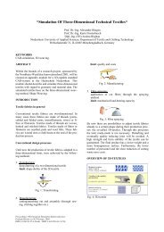
72 bit 54 bit 0-2745 bit<br />
ACCESS PACKET<br />
PAYLOAD<br />
CODE HEADER<br />
Fig. 1. ACL Packet Structure<br />
Asynchronous links use a family of packet types that<br />
mostly differ in payload size and their use of optional <strong>for</strong>ward<br />
error correction <strong>for</strong> payload data. The general <strong>for</strong>mat<br />
of an ACL packet is summarized in figure 1. All ACLpackets<br />
consist of a trailing access code block, a packet<br />
header and the data payload. The access code contains a<br />
synchronization pattern needed <strong>for</strong> radio timing synchronization<br />
and allows receiving devices to decide if the packet<br />
is addressed to its logical channel. The access code is<br />
not compared bitwise but with an auto-correlation mechanism.<br />
The configuration of the auto-correlator defines the<br />
robustness against erroneous bits in the access code or trailing/missing<br />
bits due to synchronization drifts. The packet<br />
header contains the active slave address, packet type, flow<br />
control, sequence numbering, acknowledgment in<strong>for</strong>mation<br />
and an 8 bit header checksum (HEC) that ensures the correctness<br />
of the header in<strong>for</strong>mation. The header is additionally<br />
protected by a <strong>for</strong>ward error correction code that<br />
replicates the data 3 times. The payload field consists of a<br />
payload header, the payload data and a 16 bit CRC checksum.<br />
Payload header and payload data are treated as a single<br />
block on the link control layer. Different to high data rate<br />
packets (DH1, DH3, DH5) the data payload is optionally secured<br />
by a <strong>for</strong>ward error correction scheme if medium data<br />
rate packets (DM1, DM3, DM5) are used. This <strong>for</strong>ward error<br />
correction scheme groups the whole payload into blocks<br />
of 10 bit size and appends 5 bits of redundant error correction<br />
in<strong>for</strong>mation to each block.<br />
Failures on the packet header checksum or the payload<br />
checksum trigger a retransmission of the whole<br />
packet. These retransmissions occur autonomously on<br />
baseband/link-controller level and is completely out of the<br />
users control. Retransmitted packets of course increase the<br />
transmission time <strong>for</strong> the affected payload and the amounts<br />
of packets sent in total and thereby reduce the available<br />
bandwidth.<br />
III. EXISTING SIMULATION APPROACHES<br />
Bluetooth currently represents one of the mostly used adhoc<br />
communication plat<strong>for</strong>ms and has been targeted by different<br />
<strong>simulation</strong> approaches. All of them differ in topics of<br />
interests and depth of analysis. A brief selection of the most<br />
referred systems shall be given in this section.<br />
Due to the different fields of application that Bluetooth or<br />
other wireless communication systems can be used in, there<br />
are different approaches to behavioral <strong>simulation</strong> of wireless<br />
networks. With regard to their area of application they can<br />
be categorized in three classes of <strong>simulation</strong> <strong>environment</strong>s:<br />
1. Interface Simulation: Simulation of wireless communication<br />
by its external interface. This kind of <strong>simulation</strong> is<br />
mainly intended <strong>for</strong> development and testing of mobile ap-
plications. It does not necessarily cover <strong>simulation</strong> of the<br />
network architecture, the internal processing flow, the transport<br />
characteristics or security mechanisms besides of their<br />
external appearance to the application.<br />
2. Infrastructure Simulation: Simulation of the network architecture<br />
and device interaction including organizational<br />
structures like piconets and scatternets. This class of <strong>simulation</strong><br />
may include an abstraction of the radio communication<br />
as far as it is needed <strong>for</strong> the <strong>simulation</strong> of device interaction<br />
but does not necessarily cover disturbed radio or error<br />
correction mechanisms.<br />
3. Transport Simulation: Representation of the transport<br />
flow down to the physical layer including radio interferences.<br />
Pure interface <strong>simulation</strong> suites that are often hosted<br />
in application development suites <strong>for</strong> end-user application<br />
such as cell phone application are not taken into account<br />
here because they address a completely different application<br />
domain. The most important <strong>simulation</strong> <strong>environment</strong>s<br />
will be discussed in the following:<br />
• Bluehoc: Bluehoc developed of IBM India is one of the<br />
most cited <strong>simulation</strong> <strong>environment</strong>s <strong>for</strong> Bluetooth. It is<br />
based on the NS-2 network simulator [BEF + 00], [Fal00]<br />
and covers the physical layer, Baseband, Link Manager,<br />
and L2CAP protocols. Its main focus is set on infrastructure<br />
<strong>simulation</strong>. Physical constraints like mobility or explicit<br />
implementation of the radio layer have only been addressed<br />
at a high level of abstraction. Radio propagation<br />
uses the NS2 free space model representing the communication<br />
range of the transmitting device as a circle around<br />
it. Receivers within the circle receive all packets, scanning<br />
devices outside of the communication range receive<br />
nothing [Fal00]. Packet loss is modeled in a very simple<br />
table-based fashion. Applications can be simulated using<br />
predefined traffic patterns of NS-2 which covers TCP/UDP<br />
packets with source behavior models such as FTP, Telnet or<br />
HTTP [SI03]. The last releases of Bluehoc are dated in the<br />
year 2001 and though it misses the current extensions of the<br />
Bluetooth standard.<br />
• UCBT: The UCBT [WA04] Bluetooth extension <strong>for</strong> NS-2<br />
is also based on the NS-2 network simulator. It represents<br />
a more complete infrastructure <strong>simulation</strong> <strong>environment</strong> than<br />
Bluehoc that is partially ported to the current Bluetooth standard<br />
version 1.2. It provides an extended interference model<br />
based on interference queues as well as the original Bluehoc<br />
mechanism but physical channel / radio layer is not implemented<br />
either. Mobility is implemented using the Wireless<br />
LAN (WLAN) node model of NS-2. Application <strong>simulation</strong><br />
also uses the NS-2 functionality as described <strong>for</strong> Bluehoc.<br />
UCBT is still under development and apart of its functional<br />
volume it is currently difficult to use due to the missing documentation.<br />
• Suitetooth [Hig01] is the official Bluetooth implementation<br />
of the commercial OPNET network <strong>simulation</strong> framework.<br />
Suitetooth is referenced as an extraction of Bluetooth<br />
key features with a strong focus on transport and interference<br />
<strong>simulation</strong> including an explicit model of the physical<br />
radio layer. Suitetooth benefits from the network <strong>simulation</strong><br />
functionality of OPNET giving a strong focus on analysis<br />
of TCP/IP transport over Bluetooth links. The link management<br />
protocol layer (LMP) is not implemented in Suitetooth<br />
but a user interface <strong>for</strong> own link manager implementations is<br />
provided instead. There<strong>for</strong>e many characteristic Bluetooth<br />
functionalities depending on the link manager e.g. piconets<br />
are not supported without further development. Application<br />
<strong>simulation</strong> is implemented uses OPNET traffic source profiles<br />
similar to the NS-2 based systems.<br />
• Conti and Moretti [CM05] give a new approach by referring<br />
to Bluetooth link manager and baseband <strong>simulation</strong><br />
based on the SystemC hardware modeling plat<strong>for</strong>m. The<br />
projects addresses the power dissipation and per<strong>for</strong>mance<br />
analysis of Bluetooth in presence of noise with respect to<br />
the use of different packet types. The <strong>simulation</strong> <strong>environment</strong><br />
provides a custom application interface <strong>for</strong> embedding<br />
SystemC based Bluetooth <strong>applications</strong>. The host controller<br />
interface and the physical layer are left out of scope in this<br />
approach.<br />
Furthermore there are other <strong>simulation</strong> approaches addressing<br />
detailed aspects of Bluetooth e.g. Xiong and Pollard<br />
[XP05] do detailed analysis on Bluetooth transport reliability<br />
and provide a <strong>simulation</strong> model <strong>for</strong> the GFSK modulation<br />
of the Bluetooth radio layer.<br />
Currently, there is no <strong>simulation</strong> <strong>environment</strong> covering all<br />
Bluetooth layers from PHY to HCI. Neither does any of the<br />
named systems provide an interface capable of applying it<br />
to custom <strong>applications</strong>. Typically the <strong>simulation</strong> <strong>environment</strong>s<br />
provide application behavior interfaces controlled by<br />
scripting languages allowing basic creation and movement<br />
operations in conjunctions with synthetic traffic generators<br />
and loss models.<br />
IV. SIMULATION REQUIREMENTS<br />
From the networking point of view in<strong>for</strong>mation on connection<br />
robustness, effectively available bandwidth and latency<br />
characteristics are important measures that have to be<br />
taken into account <strong>for</strong> the network design.<br />
As stated in section II Bluetooth packets have different<br />
safety features <strong>for</strong> different packet types and even <strong>for</strong> the<br />
different parts of a single packet. There<strong>for</strong>e transmission errors<br />
have different impact on the communication depending<br />
on the position of their occurrence in the packet. Regarding<br />
this, it will not be sufficient to simulate a packet as a single<br />
event with static loss and interference probabilities to get a<br />
detailed view on communication per<strong>for</strong>mance and reliability.<br />
When certain in<strong>for</strong>mation on the network layer characteristics<br />
are needed it becomes mandatory to simulate the communication<br />
down to the resolution of single network token<br />
leading to a time-slice based <strong>simulation</strong>al model.<br />
V. SIMULATION CONCEPT<br />
The given concept basically uses strict encapsulation of<br />
the different entities acting together in the process of wireless<br />
communication. All entities interact using defined interfaces<br />
that try to represent the abilities of the ’real life scenario’<br />
as close as possible. Figure 2 gives an overview of<br />
the involved entities. Their function is explained in the following<br />
sections.<br />
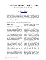
The base of the <strong>simulation</strong> is built up from a simulated<br />
world called BTWorld that interacts with multiple radio en-
Fig. 3. Structure of Radio Enabled Entities<br />
Fig. 2. Entity-Relationship Model of the Simulation Environment<br />
abled mobile entities named HFEntities. All HFEntities are<br />
related to a corresponding location record that represents its<br />
geographical position in the simulated world and to a HF-<br />
Properties record that represents its current radio setup (e.g.<br />
the frequency the device is tuned to).<br />
A. Timing<br />
Timing and synchronization are critical issues on Bluetooth<br />
communication. To gain precise in<strong>for</strong>mation on device<br />
interaction preceding the synchronization process as<br />
in connection establishment, inquiry or piconet changes on<br />
scatternets, the timing model should orient as much on real<br />
behavior as possible. This implies the use of time-slice<br />
based <strong>simulation</strong> instead of an event driven architecture or<br />
statistical models.<br />
The BTWorld entity is related to a single master clock<br />
that represents the global <strong>simulation</strong> clock and is the base<br />
<strong>for</strong> all other clocks instantiated in the <strong>simulation</strong> <strong>environment</strong>.<br />
Slave clocks are instantiated by mobile devices. Slave<br />
clocks may directly <strong>for</strong>ward the timing of the master clock<br />
to simulate a perfect clock or they may simulate clock skews<br />
by dropping clock ticks of the master clock. Simulation of<br />
a single slave clock running faster than the others has to<br />
be simulated originating from the master clock by dropping<br />
clock cycle of the slower slaves because no slave should be<br />
clocked faster than the Radio Kernel to prevent false detections<br />
of erroneous radio access.<br />
Timing requirements can directly be derived from the<br />
Bluetooth standard. Bluetooth symbol transmission time<br />
of 1µs directly implies a minimum <strong>simulation</strong> timing resolution<br />
of 1µs. For the maximum useful resolution it can<br />
be regarded that Bluetooth radio timing is resynchronized<br />
with the synchronization word at the beginning of each<br />
packet. With a maximum packet length of 2871 bits in DH5-<br />
Packets, the specified minimum radio timing accuracy of<br />
+/- 20 ppm leads to a maximum error of 2 ∗ 20/1000000 ∗<br />
2871µs =0.12µs [BS02], [Blu03]. This is less than one<br />
eighth of the symbol duration giving the receiving radio<br />
module enough time to accurately decode all symbols until<br />
the next resynchronization takes place. There<strong>for</strong>e a correctly<br />
synchronized Bluetooth piconet will never suffer that<br />
much clock skew so that a <strong>simulation</strong> resolution of more<br />
then 1µs would give an increase on <strong>simulation</strong> quality.<br />
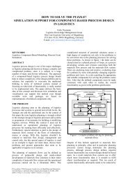
B. Radio Enabled Entities<br />
All radio enabled entities which are namely Bluetooth devices<br />
(BTEntities) or sources of local radio disturbance have<br />
to extend the abstract HFEntity model. HFEntities mainly<br />
provide a position record and an HFProperties record. The<br />
position record keeps the local positioning in<strong>for</strong>mation in<br />
the simulated world. See figure 3 <strong>for</strong> the structure of HFEntity<br />
models. The HFProperties record represents the current<br />
radio configuration as the transmission power or the frequency<br />
the simulated antenna is currently tuned to. BTEntity<br />
represent the Bluetooth enabled extension of the HFEntities.<br />
BTEntities consists of a multi-layer model correlating<br />
to the layers of Bluetooth data processing. Additionally<br />
the BTEntity contains a simulated radio clock derived<br />
from the world clock and a Bluetooth clock derived from<br />
its own radio clock. The radio clock provides the timing<br />
needed <strong>for</strong> the symbol duration at the medium where the<br />
Bluetooth clock gives the half slot timing (312.5µs) needed<br />
<strong>for</strong> almost all timing constraints of baseband and link controller<br />
layer. The radio clock corresponds to the Bluetooth<br />
clock as defined in the Bluetooth specification [Blu03] and<br />
the BTClock corresponds to the simulated oscillator crystal<br />
timing.<br />
C. Monitoring Interface<br />
All layers of Bluetooth packet processing are connected<br />
to a monitoring interface. Each data or command packet<br />
triggers a monitoring event <strong>for</strong> each processing layer it<br />
passes. Together with the events in<strong>for</strong>mation on the device<br />
state, device clock as well as layer specific actions<br />
such as encryption, checksum calculation, error correction<br />
and retransmit filtering are provided to the monitor instance.<br />
Monitor instances can be user specific acquisition modules,<br />
graphical interfaces or the system internal file logger. By<br />
masking out selected layers of the Bluetooth protocol stack,<br />
the monitoring subsystem gives the application developer<br />
all the needed in<strong>for</strong>mation to trace back the influence of the<br />
chosen setup down to all layers of Bluetooth packet handling.<br />
D. Simulation Control<br />
The <strong>simulation</strong> flow can be controlled by a dedicated <strong>simulation</strong><br />
application that is able to instantiate HFEntities in<br />
the BTWorld and to access the HCI. Alternatively, it can associate<br />
the HCI to a system socket, enabling the <strong>simulation</strong><br />
to connect to an external application. In either case the <strong>simulation</strong><br />
application is responsible to spawn in HFEntity into
the BTWorld <strong>environment</strong> and manage the positioning and<br />
the movements of the mobile entity.<br />
E. Radio Model<br />
Though it is the most critical part to assure a correct <strong>simulation</strong><br />
behavior, the <strong>simulation</strong> of the radio medium is encapsulated<br />
in a separate module that is connected to the BT-<br />
World entity. The interfacing between BTWorld and the radio<br />
kernel is done by an interface providing a transmit operation<br />
that take the current payload symbol, the senders location<br />
record and the HFProperties as arguments. The second<br />
operation provided by the radio kernel is a receive method<br />
that takes the receivers location record and HFProperties to<br />
synthesize the resulting payload symbol from the radio state.<br />
The radio kernel takes the responsibility to verify all radio<br />
activity <strong>for</strong> validity.<br />
VI. RADIO KERNEL<br />
With the fact that Bluetooth devices can only possess one<br />
antenna per device that can either be in transmit or in receive<br />
mode <strong>for</strong> the duration of one time-slot the radio entities can<br />
be modeled by three states:<br />
• no radio access<br />
• transmit<br />
• receive<br />
To derive result <strong>for</strong> the receive operation from the media<br />
state, all transmit operations have to be finished be<strong>for</strong>e the<br />
receive operation can take place. There<strong>for</strong>e the time-slice is<br />
divided into two stages: the TX-PHASE <strong>for</strong> transmissions<br />
and the RX-PHASE <strong>for</strong> receive operations. These stages<br />
are delimited by synchronization barriers.<br />
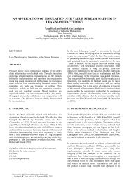
start-barrier<br />
phase1-barrier<br />
finish-barrier<br />
TX-PHASE<br />
RX-PHASE<br />
Fig. 4. Radio control flow<br />
Each <strong>simulation</strong> round begins with a start barrier that all<br />
participating devices have to pass <strong>for</strong> the <strong>simulation</strong> round to<br />
start. The stage1- and the finish-barrier are initialized with<br />
the amount of devices that passed the start-barrier. Each<br />
barrier can only be passed if it has been reached by all devices.<br />
If a devices triggers a transmit operation its transmission<br />
payload symbol is stored together with the state of<br />
its radio parameters and its position coordinates. A transmit<br />
operation automatically calls the stage1-barrier which<br />
causes the device to be blocked until all remaining devices<br />
have called the stage1-barrier as well. Thereby it is guaranteed<br />
that all devices are only able to transmit once per round.<br />
If a device executes a receive operation the stage1-barrier is<br />
reached and the device is blocked until the stage1-barrier is<br />
released. After all devices have reached the phase1-barrier,<br />
it is unlocked and the RX-PHASE is triggered. For each device<br />
that has been blocked in a receive operation its result<br />
is calculated by a comparison of the receivers radio parameters<br />
and location coordinates compared to the transmissions<br />
stored in the TX-PHASE. If any device tries to call a receive<br />
or transmit operation after the stage1-barrier has been<br />
passed this indicates an error in the <strong>simulation</strong> implementation.<br />
If all devices finish their <strong>simulation</strong> round they reach<br />
their finish routine that triggers the finish barrier. If a device<br />
does not trigger any receive or transmit action in the<br />
current round, it directly reaches its finish routine without<br />
being blocked by any barriers. In this case the finish routine<br />
also counts down the stage1-barrier not to lock the other devices<br />
in the RX-PHASE. After all devices have reached the<br />
finish barrier the beginning of the next <strong>simulation</strong> round is<br />
triggered <strong>for</strong> the simulated devices and the radio kernel.<br />
The level of detail regarding the radio modulation and the<br />
<strong>simulation</strong> aspects are likely to be kept customizable. This<br />
allows to implement time-efficient models similar to the<br />
’free space model’ of Bluehoc (see section III) or more complex<br />
<strong>simulation</strong> models e.g. given in [XP05] or [SHS02].<br />
VII. IMPLEMENTATION<br />
The concept has been realized as a Java framework currently<br />
referenced as ’SimBA’. The actual state of implementation<br />
covers most common functionality of the HCI that is<br />
needed <strong>for</strong> inquiry of devices, connection establishment and<br />
AIL data transfer.<br />
Header error checksums, payload CRC checksums as<br />
well as <strong>for</strong>ward error correction have been fully implemented<br />
regarding the Bluetooth Specification [Blu03]. Implementation<br />
of synchronous connections (SCO) and encryption<br />
functionality have been postponed. Frequency hopping<br />
is still limited to the non-adaptive scheme from Bluetooth<br />
version 1.1, but the adaptive scheme of Bluetooth 1.2<br />
is scheduled <strong>for</strong> implementation.<br />
The system comes with two different radio kernel implementations.<br />
The first one uses a simple radio propagation<br />
model similar to BlueHoc (see section III).<br />
The other radio kernel is based on the path-loss and interference<br />
model given in [Mor02]. This <strong>simulation</strong> model allows<br />
to give a path-loss parameter n as a measure <strong>for</strong> the <strong>environment</strong>al<br />
communication characteristics. The basic principle<br />
<strong>for</strong> path-loss PLcalculation is the equation<br />
( ) 4Π<br />
PL =20log +10n ∗ log(d)<br />
λ<br />
with distance d between the sending and receiving device,<br />
wavelength λ and path-loss exponent n. The<br />
wavelength λ <strong>for</strong> a frequency of 2.4 GHz is fixed at<br />
299,792,458m/s<br />
2.4∗10 9 /s<br />
≈0.125m [Mor02]. This substitution gives<br />
the final basic path-loss <strong>for</strong>mula<br />
PL =40+10n ∗ log(d)<br />
that can be used to calculate the path-loss <strong>for</strong> given d and n.<br />
With the path-loss given in dBm and the knowledge of the<br />
senders output power it can be estimated if the receiver is<br />
able to receive the signal properly. It can also be solved to d<br />
as the maximum range <strong>for</strong> given path-loss PLand path-loss<br />
exponent n in the <strong>for</strong>m of d =10 PL−40<br />
10n where PL is the<br />
difference between the transmitter output power in dBm and<br />
the receiver sensitivity, giving the maximum transmission<br />
range <strong>for</strong> the devices configuration.
This model will allow a more realistic <strong>simulation</strong> of communication<br />
characteristics by a moderate reduction of <strong>simulation</strong><br />
per<strong>for</strong>mance. Assuming the path-loss exponent n is<br />
fixed <strong>for</strong> one <strong>simulation</strong> run, this model causes an overhead<br />
of one logarithm-operation and one multiplication per transferred<br />
token multiplied by the number of possible receivers.<br />
VIII. CONCLUSION<br />
In this paper some of the most common <strong>simulation</strong> <strong>environment</strong>s<br />
have been analyzed regarding the completeness<br />
of the simulated Bluetooth implementation and their usability<br />
with custom ad-hoc network <strong>applications</strong>. The research<br />
came to conclusion that none of the chosen <strong>environment</strong>s<br />
provide sufficient support <strong>for</strong> <strong>simulation</strong> based analysis of<br />
user defined ad-hoc networking <strong>applications</strong>.<br />
Based on this conclusion, requirements <strong>for</strong> a <strong>simulation</strong><br />
<strong>environment</strong> capable of simulating custom Bluetooth application<br />
have been cumulated and a custom <strong>simulation</strong> concept<br />
has been developed and partially implemented.<br />
The <strong>simulation</strong> framework allows implementation of custom<br />
Bluetooth <strong>applications</strong> and detailed analysis of its communication<br />
characteristics down to logical transport or even<br />
the physical transport layer. So, resource critical <strong>applications</strong><br />
can be optimized <strong>for</strong> proper operation by analysis of<br />
the logical and physical transport characteristics which are<br />
completely hidden by the Bluetooth API in hardware implementations.<br />
The impact of <strong>environment</strong>al radio characteristics<br />
can be analyzed by adjusting the path-loss parameters<br />
to get detailed in<strong>for</strong>mation on the application behavior in<br />
locations with different radio characteristics. By the results<br />
of the <strong>simulation</strong>, the target application can be optimized <strong>for</strong><br />
bandwidth or latency by tracing back the impact on different<br />
packet sizes and error correction schemes.<br />
REFERENCES<br />
[BEF + 00] L. Breslau, D. Estrin, K. Fall, S. Floyd, J. Heidemann,<br />
A. Helmy, P. Huang, S. McCanne, K. Varadhan, Y. Xu, and<br />
H. Yu. Advances in network <strong>simulation</strong>. IEEE Computer,<br />
33(5):59–67, 2000.<br />
[Blu03] Bluetooth SIG. Specification of the Bluetooth System. v1.2.<br />
www.<strong>bluetooth</strong>.org, 2003.<br />
[BS02] Jennifer Bray and Charles F. Sturman. Bluetooth 1.1: Connect<br />
without Cables. P T R Prentice-Hall, Englewood Cliffs, NJ<br />
07632, USA, 2002.<br />
[CM05] M. Conti and D. Moretti. System level analysis of the <strong>bluetooth</strong><br />
standard. Proceedings of the conference on Design, Automation<br />
and Test in Europe, 3:118–123, 2005.<br />
[Fal00] K. Fall. ns Notes and Documentation.<br />
www.isi.edu/nsnam/ns/ns-documentation.html, 2000.<br />
[Hig01] Highland Systems, Inc. Bluetooth Simulation Model Suite<br />
<strong>for</strong> OPNET. http://www.highsys.com/products/Suitetooth.pdf,<br />
2001.<br />
[Mor02] R. Morrow. Bluetooth: Operation and Use. McGraw-Hill<br />
Professional, New York, USA, 2002.<br />
[MZP04] D. Miorandi, A. Zanella, and G. Pierobon. Per<strong>for</strong>mance evaluation<br />
of <strong>bluetooth</strong> polling schemes: an analytical approach.<br />
Mobile Networks and Applications, 9:63–72, February 2004.<br />
[SHS02] R. Schiphorst, F.W. Hoeksema, and C.H. Slump. Bluetooth<br />
demodulation algorithms and their per<strong>for</strong>mance. Proceedings<br />
of the workshop on Software Radios, pages 20–21, 2002.<br />
[SI03] M. Subramani and M. Ilyas. Simulation Based Analysis<br />
of Bluetooth Networks. 2003 International Symposium on<br />
Per<strong>for</strong>mance Evaluation of Computer and Telecommunication<br />
Systems, pages 688–694, 2003.<br />
[WA04] Q. Wang and D. Agrawal. UCBT – Bluetooth extension <strong>for</strong><br />
NS2. www.ececs.uc.edu/ cdmc/ucbt, 2004.<br />
[XP05] X. Xiong and J. Pollard. Modelling <strong>for</strong> <strong>bluetooth</strong> pan reliability.<br />
Proceedings of 19th European Conference on Modelling<br />
and Simulation, pages 580–584, 2005.