optimization and control of batch reactor by ... - ResearchGate
optimization and control of batch reactor by ... - ResearchGate
optimization and control of batch reactor by ... - ResearchGate

You also want an ePaper? Increase the reach of your titles
YUMPU automatically turns print PDFs into web optimized ePapers that Google loves.
OPTIMIZATION AND CONTROL OF BATCH REACTOR BY<br />
EVOLUTIONARY ALGORITHMS<br />
Roman Senkerik<br />
Ivan Zelinka<br />
Department <strong>of</strong> Applied Informatics<br />
Tomas Bata University<br />
Nad Stranemi 4511, Zlin 760 05, Czech Republic<br />
E-mail: zelinka@ft.utb.cz , senkerik@ft.utb.cz<br />
ABSTRACT<br />
This work deals with using a method <strong>of</strong> artificial<br />
intelligence, namely the evolutionary algorithm SOMA,<br />
for static <strong>optimization</strong> <strong>of</strong> a chemical <strong>batch</strong> <strong>reactor</strong>, for<br />
the purpose to improve its behavior in un<strong>control</strong>led<br />
state <strong>and</strong> predictive <strong>control</strong>. The importance <strong>of</strong> this<br />
problem is increasing with growing dem<strong>and</strong> for special<br />
products made in <strong>batch</strong> <strong>reactor</strong>s. The <strong>optimization</strong>s has<br />
been performed in several ways, each one for another<br />
set <strong>of</strong> <strong>reactor</strong> parameters or another cost function. The<br />
<strong>optimization</strong> gave the best solution, which improved the<br />
performance <strong>of</strong> the <strong>reactor</strong>. All the important results <strong>of</strong><br />
each <strong>optimization</strong> are discussed continuously <strong>and</strong> at the<br />
end <strong>of</strong> the paper too. The optimized <strong>reactor</strong> was used in<br />
a simulation with predictive <strong>control</strong> <strong>by</strong> the evolutionary<br />
algorithms <strong>and</strong> excellent results were achieved.<br />
INTRODUCTION<br />
Chemical industry produces a whole range <strong>of</strong> products<br />
through physical <strong>and</strong> chemical reactions. Successful<br />
mastering <strong>of</strong> the chemic-technological process requires<br />
its quantitative <strong>and</strong> qualitative assessment. This is<br />
particularly necessary in the cases where an<br />
introduction <strong>of</strong> automatic <strong>control</strong> systems <strong>of</strong><br />
technological procedures is under consideration. In<br />
order to prevent computer-<strong>control</strong> modernization <strong>of</strong><br />
existing <strong>and</strong> future processes becoming an end in itself,<br />
it is necessary to proceed in individual stages.<br />
The most important stage is an analysis <strong>of</strong> the<br />
manufacturing system, which in most cases comprises<br />
simulating calculations based on a realistic<br />
underst<strong>and</strong>ing <strong>of</strong> physic-chemical mechanisms through<br />
which initial raw materials are converted into the<br />
required product. These calculations then reveal key<br />
points <strong>of</strong> the technological process which <strong>by</strong> their<br />
nature enforce changes <strong>and</strong> adjustments <strong>of</strong> the<br />
technological procedure so that potential automation<br />
produces the required effect, i.e. a quality product at<br />
minimal production costs.<br />
Generally it may be stated that key technological points<br />
are chemical <strong>reactor</strong>s. Designing optimal <strong>reactor</strong><br />
parameters including <strong>control</strong> constitutes one <strong>of</strong> the most<br />
complex tasks in process engineering. The situation is<br />
particularly complicated <strong>by</strong> the fact that the precise<br />
mechanism <strong>of</strong> chemical reaction kinetics is very <strong>of</strong>ten<br />
unknown. For this reason it is necessary to carry out<br />
extensive measurements <strong>of</strong> input <strong>and</strong> output<br />
concentration dependencies <strong>of</strong> components on time,<br />
temperature, etc. These quite complex kinetic models,<br />
verified <strong>of</strong> course <strong>by</strong> experimental measurements, are<br />
subsequently linearized employing various methods,<br />
which enables to apply already developed <strong>control</strong><br />
methods to these models.<br />
Disregarding the petrochemical field, attention <strong>of</strong><br />
chemical industry is mostly given to raw materials for<br />
producing macromolecular materials, i.e. plastics. Highmolecular<br />
compounds arise through two types <strong>of</strong><br />
reactions, polymeration <strong>and</strong> polycondensation. What is<br />
essential for designing algorithms <strong>control</strong>ling such<br />
reactions is the fact that the majority <strong>of</strong> these reactions<br />
are exothermic, i.e. releasing heat. From the viewpoint<br />
<strong>of</strong> economy, productivity <strong>of</strong> the chemical <strong>reactor</strong> is<br />
usually dem<strong>and</strong>ed to be in a certain respect maximal,<br />
<strong>and</strong> final-product quality to be as required. Reactor<br />
productivity depends on reaction rate, which usually<br />
increases exponentially with increasing temperature.<br />
At first sight it seems that an exothermal character <strong>of</strong> a<br />
reaction is very advantageous. This conclusion is true to<br />
a certain extent, nevertheless, as with all, it also has<br />
limitations regarding both safety <strong>and</strong> quality (e.g.<br />
product quality may be degraded with increased<br />
temperature).<br />
This is particularly true if the main reaction is<br />
accompanied with undesired side reactions whose rates<br />
also increase exponentially with temperature. Hence, it<br />
is apparent that the principal <strong>control</strong>led quantity in<br />
exothermal reactions is temperature <strong>of</strong> reaction mixture.<br />
Therefore, models presented in this work are based on<br />
entalpic balances enabling relevant simulations.<br />
Characteristics <strong>of</strong> <strong>batch</strong> processes<br />
The <strong>optimization</strong> <strong>of</strong> <strong>batch</strong> processes has attracted<br />
attention in recent years (Aziz et al. 2000), (Silva et al.<br />
2003) because, in the face <strong>of</strong> growing competition, it is<br />
a natural choice for reducing production costs,<br />
improving product quality, meeting safety requirements<br />
<strong>and</strong> environmental regulations. Batch <strong>and</strong> semi-<strong>batch</strong><br />
processes are <strong>of</strong> considerable importance in the fine<br />
chemicals industry. A wide variety <strong>of</strong> special chemicals,<br />
pharmaceutical products, <strong>and</strong> certain types <strong>of</strong> polymers<br />
are manufactured in <strong>batch</strong> operations. Batch processes<br />
are typically used when the production volumes are
low, when isolation is required for reasons <strong>of</strong> sterility or<br />
safety, <strong>and</strong> when the materials involved are difficult to<br />
h<strong>and</strong>le. In <strong>batch</strong> operations, all the reactants are charged<br />
in a tank initially <strong>and</strong> processed according to a predetermined<br />
course <strong>of</strong> action during which no material is<br />
added or removed. In semi-<strong>batch</strong> operations, a reactant<br />
may be added with no product removal, or a product<br />
may be removed with no reactant addition, or a<br />
combination <strong>of</strong> both. From a process systems point <strong>of</strong><br />
view, the key feature that differentiates continuous<br />
processes from <strong>batch</strong> <strong>and</strong> semi-<strong>batch</strong> processes is that<br />
continuous processes have a steady state, whereas <strong>batch</strong><br />
<strong>and</strong> semi-<strong>batch</strong> processes do not (Srinisavan 2000 et al.<br />
2002a <strong>and</strong> 2000b)<br />
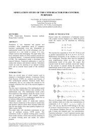
DESCRIPTION OF REACTOR<br />
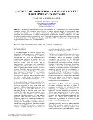
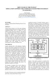
This work used a mathematical model <strong>of</strong> <strong>reactor</strong> shown<br />
in Fig.1. This chemical <strong>reactor</strong> was designed for<br />
chemic-technological process <strong>of</strong> leather manufacturing<br />
waste processing, which is a huge ecologic problem<br />
world-wide. Successful determination <strong>of</strong> the <strong>reactor</strong><br />
optimal parameters <strong>and</strong> improved <strong>control</strong> <strong>of</strong> the whole<br />
process will help to elaborate a propose <strong>of</strong><br />
technological plant, which will be able to satisfy<br />
economical <strong>and</strong> quality requirements.<br />
The <strong>reactor</strong> has two physical inputs (one for chemical<br />
substances <strong>and</strong> one for cooling medium) <strong>and</strong> one output<br />
(cooling medium). Equations (1) <strong>and</strong> (2) represent the<br />
mathematical model <strong>of</strong> the <strong>reactor</strong>.<br />
flows out through second output, with parameters mass<br />
flow rate m V , temperature T V <strong>and</strong> specific heat c V .<br />
At the beginning <strong>of</strong> the process there is an initial <strong>batch</strong><br />
inside the <strong>reactor</strong> with parameter mass m P . The<br />
chemical FK is then added to this initial <strong>batch</strong>, so the<br />
reaction mixture inside the <strong>reactor</strong> has total mass m,<br />
temperature T <strong>and</strong> specific heat c R <strong>and</strong> also contains<br />
partially unreacted portions <strong>of</strong> chemical FK described<br />
<strong>by</strong> parameter concentration a FK .<br />
This technique partially allows <strong>control</strong>ling the<br />
temperature <strong>of</strong> reaction mixture <strong>by</strong> the <strong>control</strong>led<br />
feeding <strong>of</strong> the input chemical FK<br />
The main objective <strong>of</strong> <strong>optimization</strong> is to achieve the<br />
processing <strong>of</strong> large amount <strong>of</strong> chemical FK in very<br />
short time. An exothermal reaction described <strong>by</strong><br />
relationships (1) – (3) takes place in the <strong>reactor</strong>.<br />
In general, this reaction is highly exothermal. Hence,<br />
the most important parameter is the temperature <strong>of</strong> the<br />
reaction mixture. This temperature must not exceed<br />
100°C because <strong>of</strong> safety aspects <strong>and</strong> quality <strong>of</strong><br />
processing,<br />
Designing the <strong>reactor</strong> was based on st<strong>and</strong>ard chemicaltechnological<br />
methods <strong>and</strong> gives a proposal <strong>of</strong> <strong>reactor</strong><br />
physical dimensions <strong>and</strong> parameters <strong>of</strong> chemical<br />
substances. These values are called in this work expert<br />
parameters. The objective <strong>of</strong> this part <strong>of</strong> the work was<br />
to perform a simulation <strong>and</strong> <strong>optimization</strong> <strong>of</strong> the given<br />
<strong>reactor</strong>.<br />
Non-linear model <strong>of</strong> <strong>reactor</strong><br />
Description <strong>of</strong> the <strong>reactor</strong> applied a system <strong>of</strong> four<br />
balance equations (2). The first expresses a mass<br />
balance <strong>of</strong> reaction mixture inside the <strong>reactor</strong>, the<br />
second a mass balance <strong>of</strong> the chemical FK, <strong>and</strong> the last<br />
two formulate entalpic balances, namely balances <strong>of</strong><br />
reaction mixture <strong>and</strong> cooling medium. Equation (1), in<br />
which (2) is represented <strong>by</strong> term “k”, is written out here<br />
for simplified notation <strong>of</strong> basic equations.<br />
m [t]<br />
(1)<br />
m FK<br />
m<br />
FK<br />
m[ t]<br />
a<br />
[ t]<br />
k m[<br />
t]<br />
a [ t]<br />
FK<br />
FK<br />
Fig.1 Scheme <strong>of</strong> <strong>reactor</strong><br />
Chemical FK flows into the <strong>reactor</strong> through the input<br />
denoted “Chemical FK”, with parameters temperature<br />
T FK , mass flow rate m FK <strong>and</strong> specific heat c FK . The<br />
coolant flows into <strong>reactor</strong> through the second input<br />
denoted “Cooling medium”, which is usually water <strong>of</strong><br />
temperature T VP , mass flow rate m V <strong>and</strong> specific heat<br />
c V .<br />
Cooling medium flows through jacket inner space <strong>of</strong><br />
<strong>reactor</strong>, with volume related to mass flow rate m VR , <strong>and</strong><br />
m<br />
FK<br />
c<br />
FK<br />
T<br />
FK<br />
H<br />
k m[<br />
t]<br />
a<br />
K S ( T[<br />
t]<br />
T<br />
[ t])<br />
m[<br />
t]<br />
c<br />
m<br />
c T<br />
V<br />
V<br />
VP<br />
<br />
V<br />
r<br />
FK<br />
R<br />
[ t]<br />
<br />
T[<br />
t]<br />
K S ( T[<br />
t]<br />
T<br />
[ t])<br />
m<br />
c T [ t]<br />
m c T[<br />
t]<br />
E<br />
R T[t]<br />
V<br />
V<br />
V<br />
V<br />
VR V<br />
k A e<br />
(2)<br />
V
After modification into st<strong>and</strong>ard form, balance<br />
equations are obtained in form (3)<br />
m [ t]<br />
<br />
(3)<br />
a<br />
FK<br />
T [<br />
t]<br />
<br />
m FK<br />
m<br />
FK<br />
[ t]<br />
A e<br />
m[<br />
t]<br />
m<br />
FK<br />
c<br />
FKT<br />
<br />
m[<br />
t]<br />
c<br />
R<br />
FK<br />
m<br />
V T<br />
TV<br />
[ t]<br />
<br />
m<br />
VR<br />
VP<br />
A e<br />
<br />
E<br />
<br />
R T[<br />
t]<br />
E<br />
<br />
R T[<br />
t]<br />
VR<br />
V<br />
a<br />
R<br />
FK<br />
H<br />
c<br />
[ t]<br />
r<br />
a<br />
A[<br />
t]<br />
K S T[<br />
t]<br />
K S TV<br />
[ t]<br />
<br />
m[<br />
t]<br />
c m[<br />
t]<br />
c<br />
K S T[<br />
t]<br />
K S TV<br />
[ t]<br />
m<br />
V TV<br />
[ t]<br />
<br />
m c m c m<br />
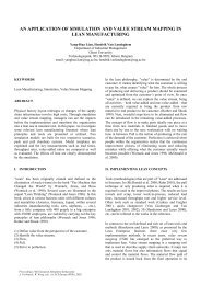
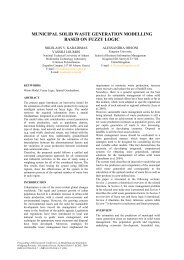
Parameters for this <strong>reactor</strong> <strong>and</strong> initial conditions (a FK0 ,<br />
T V0 , T 0 , m 0 ,…. ) have been specified <strong>by</strong> expert, giving<br />
both physical dimensions as well as parameters <strong>of</strong><br />
individual chemical substances. These were used to<br />
simulate the behavior <strong>of</strong> this <strong>reactor</strong>. It is evident from<br />
Fig.2, that <strong>reactor</strong> behavior in compliance with<br />
parameters thus specified <strong>by</strong> expert is not quite<br />
satisfactory during the processing <strong>of</strong> one <strong>batch</strong>. The<br />
duration <strong>of</strong> the processing <strong>of</strong> one <strong>batch</strong> is given <strong>by</strong> the<br />
time from the start <strong>of</strong> the process till the reaction<br />
mixture cools down to its initial temperature T 0 .<br />
The behavior <strong>of</strong> the <strong>reactor</strong> was simulated using five<br />
different values <strong>of</strong> <strong>batch</strong>ing the chemical FK into the<br />
reaction mixture (from the range <strong>of</strong> 0 – 3 kg.s -1 ).<br />
m<br />
FK<br />
= (0,05 (violet) ; 0,1 (green) ; 0,5 (blue) ; 1 (red) ;<br />
3 (black)) kg.s -1 .<br />
VR<br />
V<br />
R<br />
VR<br />
R<br />
As these are very serious, multifold repeated static<br />
<strong>optimization</strong>s <strong>by</strong> means <strong>of</strong> SOMA algorithm has been<br />
performed, <strong>and</strong> this led to finding the <strong>reactor</strong><br />
parameters with which the <strong>reactor</strong> behavior is much<br />
more acceptable.<br />
Optimizing algorithm<br />
Optimization algorithms are a powerful tool for solving<br />
many problems in engineering practice. They are<br />
usually applied when solving a given problem<br />
analytically is impossible or unrealistic. When properly<br />
implemented, they can be employed in such manner that<br />
even frequent user’s intervention in work <strong>of</strong> the<br />
respective plant where they are applied is unnecessary.<br />
This contribution consider the use <strong>of</strong> <strong>optimization</strong><br />
algorithm SOMA. Numerous results have shown<br />
SOMA is a viable algorithm that can be used to solve<br />
many practical as well as theoretical problems. (Zelinka<br />
2004)<br />
STATIC OPTIMIZATION OF REACTOR<br />
The <strong>reactor</strong> described above, in the original set-up, gave<br />
unsatisfactory results. To improve <strong>reactor</strong> behavior,<br />
static <strong>optimization</strong> was performed using the algorithm<br />
SOMA. The <strong>optimization</strong> was performed <strong>by</strong> the<br />
following three basic methods.<br />
1. Optimization <strong>of</strong> <strong>batch</strong>ing value m<br />
FK<br />
2. Optimization <strong>of</strong> <strong>batch</strong>ing value m<br />
FK<br />
together with<br />
process parameters <strong>of</strong> the cooling medium<br />
3. Optimization that covered all previous optimized<br />
parameters, <strong>and</strong> including also <strong>optimization</strong> <strong>of</strong><br />
<strong>reactor</strong> geometry <strong>and</strong> cooling area.<br />
Each <strong>optimization</strong> was repeated ten times just in case,<br />
<strong>and</strong> separate figures present time plots <strong>of</strong> all important<br />
variables collected together in order to emphasize<br />
optimizing robustness, including courses <strong>of</strong> time<br />
evolutions from all ten simulations. The behavior <strong>of</strong> the<br />
best <strong>reactor</strong> was shown with the last <strong>optimization</strong>. A<br />
discussion on particular <strong>optimization</strong> cases follows in<br />
the sections below.<br />
Optimization <strong>of</strong> <strong>batch</strong>ing value<br />
Fig.2 Behavior <strong>of</strong> the <strong>reactor</strong> set up <strong>by</strong> means <strong>of</strong> expert<br />
parameters<br />
Facts that follow from the simulation <strong>of</strong> this strongly<br />
exothermal reaction are as follows:<br />
1. Duration <strong>of</strong> one <strong>batch</strong> cycle is approx 25 000 sec<br />
2. Temperature <strong>of</strong> reaction mixture T markedly<br />
exceeds critical limit <strong>of</strong> 100°C (373,15 K), even in<br />
case <strong>of</strong> simulation with lowest value <strong>of</strong> <strong>batch</strong>ing<br />
chemical FK into the <strong>reactor</strong>.<br />
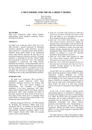
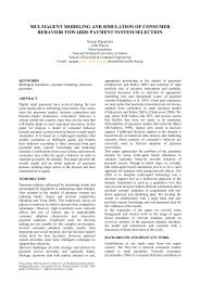
In this <strong>optimization</strong> the point was to minimize the area<br />
arising as a difference between the required <strong>and</strong> real<br />
temperature pr<strong>of</strong>ile <strong>of</strong> the reaction mixture in a selected<br />
time interval, which was the duration <strong>of</strong> a <strong>batch</strong> cycle.<br />
The required temperature was 97°C (370,15 K). The<br />
cost function that was minimized is given in (5),<br />
minimizing term which limits the maximum mass <strong>of</strong><br />
one <strong>batch</strong> in (6)<br />
f<br />
t<br />
cos t w T<br />
t<br />
(5)<br />
t0<br />
m[t] m max (6)
The simulation results are presented in Fig.3. The<br />
<strong>optimization</strong> algorithm obviously found the best value<br />
for <strong>batch</strong>ing so that the critical temperature was not<br />
exceeded. Nevertheless, the duration <strong>of</strong> the <strong>batch</strong> cycle<br />
was not shortened so the performance <strong>of</strong> the <strong>reactor</strong><br />
could not be improved without more effective cooling<br />
<strong>of</strong> the reaction mixture. Thus the next step was the<br />
second <strong>optimization</strong> covering process parameters <strong>of</strong> the<br />
cooling medium, but preserving the geometry <strong>of</strong> the<br />
<strong>reactor</strong>.<br />
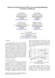
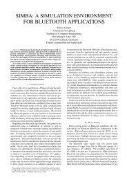
that chemical reaction was started faster <strong>and</strong> required<br />
temperature was reached in shorter time. This fact<br />
corresponds to the selected minimization functional (5),<br />
but on the other side cooling <strong>of</strong> reaction mixture was<br />
very slow after filling up the <strong>reactor</strong> <strong>and</strong> thus<br />
termination <strong>of</strong> reaction. As a result <strong>of</strong> these facts the<br />
third <strong>optimization</strong> included the <strong>optimization</strong> <strong>of</strong> <strong>reactor</strong><br />
geometry <strong>and</strong> the minimized functional had to be<br />
changed to achieve reasonable balance between the<br />
dem<strong>and</strong>s <strong>of</strong> fast start <strong>of</strong> chemical reaction, critical<br />
temperature <strong>and</strong> fast cooling to initial temperature <strong>and</strong><br />
hence to increase the performance <strong>of</strong> <strong>reactor</strong>.<br />
Tab.1 Optimized <strong>reactor</strong> parameters<br />
Parameter<br />
Range<br />
m<br />
FK<br />
[kg.s -1 ] 0 – 640<br />
T [K] 253,15 – 323,15<br />
VP<br />
m [kg.s -1 ] 0-10<br />
V<br />
Fig.3 Results <strong>of</strong> <strong>optimization</strong> <strong>of</strong> <strong>batch</strong>ing value<br />
Optimization <strong>of</strong> <strong>batch</strong>ing value <strong>and</strong> process<br />
parameters <strong>of</strong> cooling medium<br />
Optimization proceeded in the second case with the<br />
parameters that are shown in Tab.1.<br />
The actual functional that was minimized was the same<br />
as in the first case (5), minimizing term also the same as<br />
in previous case, which limits the maximum mass <strong>of</strong><br />
one <strong>batch</strong>, is presented in (6). Another restriction terms<br />
were the ranges <strong>of</strong> optimized parameters (see Tab. 1.).<br />
The results <strong>of</strong> simulations are presented in Fig.4. As can<br />
be seen, this <strong>optimization</strong> again found a good value for<br />
<strong>batch</strong>ing so that the critical temperature was not<br />
exceeded. Nevertheless, the opposite consequence was<br />
reached than required shortening duration <strong>of</strong> <strong>batch</strong> cycle<br />
<strong>and</strong> increasing the performance <strong>of</strong> <strong>reactor</strong>. The<br />
<strong>optimization</strong> found a relatively high value <strong>of</strong> the input<br />
cooling medium temperature. That essentially means<br />
Fig.4 Results <strong>of</strong> <strong>optimization</strong> <strong>of</strong> <strong>batch</strong>ing value <strong>and</strong><br />
process parameters <strong>of</strong> cooling medium
Optimization <strong>of</strong> process parameters <strong>and</strong> the <strong>reactor</strong><br />
geometry<br />
This <strong>optimization</strong> proceeded with parameters that are<br />
shown in Tab.2.<br />
Tab.2 Optimized <strong>reactor</strong> parameters<br />
Parameter<br />
Range<br />
m<br />
FK<br />
[kg.s -1 ] 0 – 640<br />
T [K] 273,15 – 323,15<br />
VP<br />
m [kg] 0 – 10<br />
V<br />
m [kg] 220<br />
VR<br />
r [m] 0,5 – 2,5<br />
h [m] 0,5 – 2,5<br />
As a result <strong>of</strong> last two simulations the actual functional<br />
that was minimized was changed to (7). It was divided<br />
into three time intervals <strong>and</strong> also two penalizations (8)<br />
<strong>and</strong> a special part were added. This special part ensures<br />
rapid reaction <strong>of</strong> the whole <strong>batch</strong> <strong>of</strong> chemical FK hence<br />
very low value <strong>of</strong> concentration a FK <strong>of</strong> partly unreacted<br />
portions <strong>of</strong> chemical FK in reaction mixture.<br />
The first penalization helps to find solutions in which<br />
the temperature <strong>of</strong> reaction mixture cools down fast to<br />
its initial state, <strong>and</strong> the process duration is shortened.<br />
The second corresponds to the critical temperature<br />
condition.<br />
The stechiometric ratio is given <strong>by</strong> (10).<br />
m 2, 82236<br />
(10)<br />
P m FK<br />
The relationship between the optimized volume <strong>of</strong><br />
<strong>reactor</strong> <strong>and</strong> the mass <strong>of</strong> added chemical FK is given <strong>by</strong><br />
(11). Then substituting to (10) gives the mass <strong>of</strong> initial<br />
<strong>batch</strong> in <strong>reactor</strong>.<br />
m<br />
FK<br />
pFKV<br />
(11)<br />
2 , 82236 <br />
FK<br />
p<br />
The results <strong>of</strong> this <strong>optimization</strong> are shown in Figs.5 <strong>and</strong><br />
6. Fig.6 demonstrates the behavior <strong>of</strong> a selected <strong>reactor</strong><br />
where predictive <strong>control</strong> was applied using algorithm<br />
SOMA. From these results it is obvious that the<br />
temperature <strong>of</strong> reaction mixture moderately exceeded<br />
the critical value, but this was a simulation <strong>of</strong><br />
un<strong>control</strong>led <strong>reactor</strong>. This can be corrected <strong>by</strong> a<br />
quality <strong>control</strong> <strong>of</strong> the <strong>batch</strong> process. Another fact not to<br />
be neglected is the shortened duration <strong>of</strong> process <strong>and</strong><br />
the improvement <strong>of</strong> <strong>reactor</strong> performance compared with<br />
the <strong>reactor</strong> set up <strong>by</strong> an expert (see Tab.3).<br />
f<br />
cos t<br />
<br />
t1<br />
<br />
t0<br />
w T<br />
t<br />
1<br />
t aFK<br />
t pen.1<br />
pen.<br />
2<br />
t0<br />
(7)<br />
T<br />
<br />
0 Max 323,15<br />
pen.1<br />
<br />
50000<br />
else<br />
for t ,t 2 3<br />
(8)<br />
0<br />
pen.2<br />
<br />
50000<br />
for 0,<br />
t3<br />
Max<br />
T<br />
<br />
else<br />
373,15<br />
where the time intervals were set for example as:<br />
t<br />
1<br />
= 15000 s; t<br />
2<br />
=20000 s; t<br />
3<br />
=25000 s<br />
The minimizing term, presented in (6), is also the same<br />
as in the previous case, which limits the maximum mass<br />
<strong>of</strong> one <strong>batch</strong>. Another restriction terms were the ranges<br />
<strong>of</strong> optimized parameters (see Tab. 2.). Moreover, many<br />
parameters were interrelated due to the <strong>optimization</strong> <strong>of</strong><br />
the <strong>reactor</strong> geometry. The relation between m, m FK <strong>and</strong><br />
m P was given <strong>by</strong> relationship (9).<br />
Fig.5 Results <strong>of</strong> <strong>optimization</strong> <strong>of</strong> process parameters <strong>and</strong><br />
<strong>reactor</strong> geometry<br />
m m p m FK<br />
(9)
height <strong>of</strong> the <strong>reactor</strong>. The meaning <strong>of</strong> the other<br />
parameters is quite obvious from the table.<br />
Tab.3 Difference between <strong>reactor</strong> designed <strong>by</strong> an expert<br />
<strong>and</strong> the optimized <strong>reactor</strong><br />
Parameter Expert setting Optimized<br />
Fig.6 Reaction mixture temperature pr<strong>of</strong>ile for the best<br />
optimized <strong>reactor</strong><br />
CONCLUSION<br />
This report describes a chemical <strong>reactor</strong> (Fig.1). After a<br />
general introduction <strong>and</strong> description <strong>of</strong> chemistry <strong>of</strong> the<br />
relevant reaction, this part discusses a nonlinear model<br />
constructed on the basis <strong>of</strong> physic-mathematical<br />
analysis<br />
(equations (1–3) including an illustrations <strong>of</strong> <strong>reactor</strong><br />
behavior based on parameters set up <strong>by</strong> an expert (see<br />
Fig.2)).<br />
Based on the obtained results, it may be claimed that the<br />
behavior <strong>of</strong> an un<strong>control</strong>led <strong>reactor</strong> gives quite<br />
unsatisfactory results, which may be overcome through<br />
static <strong>optimization</strong> <strong>of</strong> a given <strong>reactor</strong>. The quality <strong>of</strong><br />
results produced <strong>by</strong> the <strong>optimization</strong>s depends not only<br />
on the problem being solved but also on how a given<br />
functional is defined. Its construction may comprise not<br />
only <strong>optimization</strong> <strong>of</strong> a basic criterion but also<br />
<strong>optimization</strong> <strong>of</strong> subcriteria capable <strong>of</strong> improving<br />
<strong>optimization</strong> quality.<br />
Basic <strong>optimization</strong>s presented here were based on a<br />
relatively simple functional. Unless the experimenter is<br />
limited <strong>by</strong> technical issues when searching for optimal<br />
parameters, there is no problem in defining more<br />
complex functional including as subcriteria e.g.,<br />
stability, economic costs, time-optimal criteria,<br />
<strong>control</strong>lability, etc. or their arbitrary combinations.<br />
However, complexity <strong>of</strong> such functional indirectly<br />
implies the application <strong>of</strong> advanced s<strong>of</strong>tware such as<br />
Mathematica or Matlab.<br />
The advantage <strong>of</strong> parallel <strong>optimization</strong> (in the context <strong>of</strong><br />
evolutionary algorithms – i.e. “simultaneously” seeking<br />
X possible solutions <strong>and</strong> selecting the best) lies in the<br />
fact that unless an optimal solution is found, one usually<br />
obtains suboptimal solutions, which are usually not too<br />
distant from the true optimum.<br />
Differences between both <strong>reactor</strong>s are best to be seen in<br />
Tab.3. The first part shows the parameters <strong>of</strong> <strong>reactor</strong><br />
designed <strong>by</strong> an expert, <strong>and</strong> the second part shows the<br />
parameters obtained through static <strong>optimization</strong>. In<br />
Tab.3, the internal radius <strong>of</strong> <strong>reactor</strong> is expressed in<br />
parameter r <strong>and</strong> is related to cooling area “S” The<br />
parameter d represents the distance between the outer<br />
<strong>and</strong> inner jacket <strong>and</strong> the parameter h represents the<br />
m<br />
FK<br />
[kg.s -1 ] 0 - 3 0,1021<br />
T [K] 293,15 274,58<br />
VP<br />
m [kg] 1 4,67<br />
V<br />
m [kg] 220 1159,7<br />
VR<br />
d [m] 0,03 0,096<br />
r [m] 0,78 1,017<br />
h [m] 1,11 1,382<br />
S [m 2 ] 7,35 12,08<br />
V [m 3 ] 2,12 4,49<br />
m<br />
p<br />
[kg] 1810 3842,4<br />
m<br />
FK<br />
[kg] 640 1361,4<br />
Finally, on the basis <strong>of</strong> presented results it may be<br />
stated that the <strong>reactor</strong> parameters has been found <strong>by</strong><br />
<strong>optimization</strong> which demonstrates performance superior<br />
to that <strong>of</strong> <strong>reactor</strong> set up <strong>by</strong> an expert.<br />
ACKNOWLEDGEMENT<br />
This work was supported <strong>by</strong> grant No. MSM 26500014<br />
<strong>of</strong> the Ministry <strong>of</strong> Education <strong>of</strong> the Czech Republic <strong>and</strong><br />
<strong>by</strong> grants <strong>of</strong> the Grant Agency <strong>of</strong> the Czech Republic<br />
GACR 102/03/0070.<br />
REFERENCES<br />
Aziz N., Hussain M.A., Mujtaba I.M. (2000). Performance <strong>of</strong><br />
different types <strong>of</strong> <strong>control</strong>lers in tracking optimal<br />
temperature in <strong>batch</strong> <strong>reactor</strong>s. Computers <strong>and</strong> Chemical<br />
Engineering, Vol. 27, p. 1069-1075.<br />
Silva C.M., Biscaia E.C. (2003). Genetic algorithm<br />
development for multi-objective <strong>optimization</strong> <strong>of</strong> <strong>batch</strong><br />
free-radical polymerization <strong>reactor</strong>s. Computers <strong>and</strong><br />
Chemical Engineering, Vol. 27, p. 1329-1344<br />
Srinisavan B., Palanki S., Bonvin D. (2002). Dynamic<br />
<strong>optimization</strong> <strong>of</strong> <strong>batch</strong> processes I. Characterization <strong>of</strong> the<br />
nominal solution. Computers <strong>and</strong> Chemical Engineering,<br />
Vol. 27, p. 1-26.<br />
Srinisavan B., Palanki S., Bonvin D. (2002). Dynamic<br />
<strong>optimization</strong> <strong>of</strong> <strong>batch</strong> processes II. Role <strong>of</strong> Measurement<br />
in h<strong>and</strong>ling uncertainly. Computers <strong>and</strong> Chemical<br />
Engineering, Vol. 27, p. 27-44.<br />
Zelinka I. (2004) SOMA. In: B.V. Babu, G. Onwubolu Eds.,<br />
New <strong>optimization</strong> techniques in engineering, Springer-<br />
Verlag, chapter 7, ISBN 3-540-20167-X
AUTHOR BIOGRAPHIES<br />
ROMAN SENKERIK was born in Czech<br />
Republic, <strong>and</strong> went to the Tomas Bata<br />
University in Zlin, where he studied<br />
technical cybernetics <strong>and</strong> obtained his<br />
degree in 2004. He is now Ph.D. student<br />
(<strong>control</strong> <strong>of</strong> chaos <strong>by</strong> evolutionary<br />
algorithms) at the same university. His e-<br />
mail address is: senkerik@ft.utb.cz<br />
IVAN ZELINKA was born in Czech<br />
Republic, <strong>and</strong> went to the Technical<br />
University <strong>of</strong> Brno, where he studied<br />
technical cybernetics <strong>and</strong> obtained his<br />
degree in 1995. He obtained Ph.D. degree<br />
in technical cybernetics in 2001 at Tomas<br />
Bata University in Zlin. Now he is<br />
associated pr<strong>of</strong>esor (artificial intelligence, theory <strong>of</strong><br />
information) <strong>and</strong> head <strong>of</strong> department. His e-mail address is:<br />
zelinka@ft.utb.cz <strong>and</strong> his Web-page can be found at<br />
http://www.ft.utb.cz/people/zelinka.