Design and Analysis of a Hybrid Mobile Robot Mechanism ... - SEAS
Design and Analysis of a Hybrid Mobile Robot Mechanism ... - SEAS
Design and Analysis of a Hybrid Mobile Robot Mechanism ... - SEAS

You also want an ePaper? Increase the reach of your titles
YUMPU automatically turns print PDFs into web optimized ePapers that Google loves.
Pinhas Ben-Tzvi<br />
Mem. ASME<br />
e-mail: pinhas.bentzvi@utoronto.ca<br />
Andrew A. Goldenberg<br />
Fellow ASME<br />
e-mail: golden@mie.utoronto.ca<br />
Jean W. Zu<br />
Fellow ASME<br />
e-mail: zu@mie.utoronto.ca<br />
Department <strong>of</strong> Mechanical <strong>and</strong> Industrial<br />
Engineering,<br />
University <strong>of</strong> Toronto,<br />
5 Kings College Road,<br />
Toronto, ON, M5S 3G8, Canada<br />
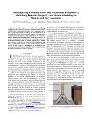
<strong>Design</strong> <strong>and</strong> <strong>Analysis</strong> <strong>of</strong> a <strong>Hybrid</strong><br />
<strong>Mobile</strong> <strong>Robot</strong> <strong>Mechanism</strong> With<br />
Compounded Locomotion <strong>and</strong><br />
Manipulation Capability<br />
This paper presents a novel design paradigm as well as the related detailed mechanical<br />
design embodiment <strong>of</strong> a mechanically hybrid mobile robot. The robot is composed <strong>of</strong> a<br />
combination <strong>of</strong> parallel <strong>and</strong> serially connected links resulting in a hybrid mechanism that<br />
consists <strong>of</strong> a mobile robot platform for locomotion <strong>and</strong> a manipulator arm for manipulation.<br />
Unlike most other mobile robot designs that have a separate manipulator arm<br />
module attached on top <strong>of</strong> the mobile platform, this design has the ability to simultaneously<br />
<strong>and</strong> interchangeably provide locomotion <strong>and</strong> manipulation capability. This robot<br />
enhanced functionality is complemented by an interchangeable track tension <strong>and</strong> suspension<br />
mechanism that is embedded in some <strong>of</strong> the mobile robot links to form the locomotion<br />
subsystem <strong>of</strong> the robot. The mechanical design was analyzed with a virtual prototype<br />
that was developed with MSC ADAMS s<strong>of</strong>tware. The simulation was used to study the<br />
robot’s enhanced mobility characteristics through animations <strong>of</strong> different possible tasks<br />
that require various locomotion <strong>and</strong> manipulation capabilities. The design was optimized<br />
by defining suitable <strong>and</strong> optimal operating parameters including weight optimization <strong>and</strong><br />
proper component selection. Moreover, the simulation enabled us to define motor torque<br />
requirements <strong>and</strong> maximize end-effector payload capacity for different robot configurations.<br />
Visualization <strong>of</strong> the mobile robot on different types <strong>of</strong> virtual terrains such as flat<br />
roads, obstacles, stairs, ditches, <strong>and</strong> ramps has helped in determining the mobile robot’s<br />
performance, <strong>and</strong> final generation <strong>of</strong> specifications for manufacturing a full scale<br />
prototype. DOI: 10.1115/1.2918920<br />
Keywords: mobile robot, hybrid mechanism, compounded locomotion <strong>and</strong> manipulation,<br />
virtual prototype, dynamic simulations<br />
1 Introduction<br />
The use <strong>of</strong> mobile robots is growing very rapidly in numerous<br />
applications such as planetary exploration, police operations e.g.,<br />
explosive ordnance disposal EOD, military operations e.g., reconnaissance<br />
missions, surveillance, <strong>and</strong> neutralization <strong>of</strong> improvised<br />
explosive device IED, hazardous site exploration, <strong>and</strong><br />
more. The use <strong>of</strong> unmanned ground vehicles UGVs in urban<br />
search <strong>and</strong> rescue USAR <strong>and</strong> military operations on urbanized<br />
terrain MOUT is gaining popularity because the mobile robots<br />
can be sent ahead or in place <strong>of</strong> humans, act on the surroundings<br />
with a manipulator arm or other active means attached to an arm,<br />
collect data about its surroundings, <strong>and</strong> send it back to the operator<br />
with no risks posed to humans.<br />
In the past decade, new designs <strong>of</strong> mobile robots have emerged<br />
<strong>and</strong> were demonstrated by both academia <strong>and</strong> industry. Our work<br />
presents a new approach to mobile robot design for locomotion<br />
<strong>and</strong> manipulation purposes for a wide range <strong>of</strong> applications <strong>and</strong><br />
practical situations. Typically, a mobile robot’s structure consist <strong>of</strong><br />
a mobile platform that is propelled with the aid <strong>of</strong> a pair <strong>of</strong> tracks,<br />
wheels, or legs, <strong>and</strong> a manipulator arm attached on top <strong>of</strong> the<br />
mobile platform to provide the required manipulation capability<br />
neutralization <strong>of</strong> bombs or l<strong>and</strong>mines, manipulation <strong>of</strong> hazardous<br />
materials, etc.. However, the presence <strong>of</strong> an arm limits the mobility.<br />
On the other h<strong>and</strong>, there are several designs <strong>of</strong> mobile robots<br />
that have pushed further the mobility state <strong>of</strong> the art such as<br />
Contributed by the <strong>Mechanism</strong>s <strong>and</strong> <strong>Robot</strong>ics Committee <strong>of</strong> ASME for publicationintheJOURNAL<br />
OF MECHANICAL DESIGN. Manuscript received July 26, 2007; final<br />
manuscript received January 25, 2008; published online May 20, 2008. Review conducted<br />
by Kwun-Lon Ting.<br />
PackBot 1,2 <strong>and</strong> Chaos 3 including the ability to return itself<br />
when flipped over, but this may not be possible if the robot is<br />
equipped with a manipulator arm. This gap is bridged in our approach<br />
by providing a new mobile robot design that provides locomotion<br />
<strong>and</strong> manipulation capabilities simultaneously <strong>and</strong> interchangeably.<br />
The new design is based on compounded locomotion <strong>and</strong> manipulation.<br />
The design approach is that the platform <strong>and</strong> manipulator<br />
arm are interchangeable in their roles in the sense that both<br />
can support locomotion <strong>and</strong> manipulation in several modes <strong>of</strong><br />
operation as discussed in Sec. 4.2. Moreover, the design architecture<br />
enables the robot to flip over <strong>and</strong> continue to operate.<br />
This paper is organized as follows. Section 2 provides a brief<br />
background to the field <strong>of</strong> mobile robots along with examples <strong>of</strong><br />
existing types <strong>of</strong> design architectures. Section 3 introduces a conceptual<br />
function-oriented analysis that outlines a summary <strong>of</strong> existing<br />
issues related to tracked mobile robots, their related research<br />
problems, <strong>and</strong> proposed solutions. The new design<br />
resulting from the analysis <strong>of</strong> the issues identified is described in<br />
Sec. 4 along with presentation <strong>of</strong> several embodiments <strong>of</strong> the<br />
proposed design approach. To realize this design, a detailed mechanical<br />
design embodiment <strong>of</strong> the mechanically hybrid mobile<br />
robot is described in detail in Sec. 5 including the design <strong>of</strong> embedded<br />
<strong>and</strong> interchangeable track tension <strong>and</strong> suspension mechanism.<br />
In Sec. 6, the mechanical design is modeled <strong>and</strong> thoroughly<br />
analyzed in order to study the robot’s functionality <strong>and</strong> optimize<br />
the design by defining suitable <strong>and</strong> optimal operating parameters<br />
such as required motor torques, manipulator end-effector capacity,<br />
etc.<br />
Journal <strong>of</strong> Mechanical <strong>Design</strong> Copyright © 2008 by ASME<br />
JULY 2008, Vol. 130 / 072302-1<br />
Downloaded 13 Jun 2008 to 128.100.48.224. Redistribution subject to ASME license or copyright; see http://www.asme.org/terms/Terms_Use.cfm
2 Background<br />
<strong>Mobile</strong> robots were used for USAR activities in the aftermath<br />
<strong>of</strong> the World Trade Center WTC attack on September 11, 2001<br />
4,5. The mobile robots were used mainly for searching <strong>of</strong> victims,<br />
searching paths through the rubble that would be quicker<br />
than to excavate, structural inspection, <strong>and</strong> detection <strong>of</strong> hazardous<br />
materials. In each case, small mobile robots were used because<br />
they could go deeper than traditional search equipment, could<br />
enter a void space that may be too small for a human or search<br />
dog, or could enter a place that posed great risk <strong>of</strong> structural<br />
collapse. Among the tracked robots that were used such as<br />
Foster-Miller’s Solem <strong>and</strong> Inuktun’s Micro-Tracs <strong>and</strong> VGTV, the<br />
capability was limited in terms <strong>of</strong> locomotion <strong>and</strong> mobility, <strong>and</strong><br />
more so if one considers requirements <strong>of</strong> manipulation with an<br />
arm mounted on the mobile robot, which were not used at all.<br />
Some <strong>of</strong> the major problems with some <strong>of</strong> the robots used on the<br />
rubble pile searches were the robot flipping over or getting<br />
blocked by rubbles into a position from where it could not be<br />
righted or moved at all.<br />
Increasingly, mobile robotic platforms are being proposed for<br />
high-risk missions for law enforcement <strong>and</strong> military applications<br />
e.g., Iraq for IEDs, hazardous site cleanups, <strong>and</strong> planetary explorations<br />
e.g., Mars rover. These missions require mobile robots<br />
to perform difficult locomotion <strong>and</strong> dexterous manipulation<br />
tasks. During such operations, loss <strong>of</strong> wheel traction, leading to<br />
entrapment, <strong>and</strong> loss <strong>of</strong> stability, leading to flipover, may occur,<br />
which results in mission failure.<br />
Various robot designs with actively controlled traction<br />
1,2,6–8, also called “articulated tracks,” were found to somewhat<br />
improve rough-terrain mobility. The mobility gains due to<br />
the articulated track mechanism yield a larger effective track radius<br />
for obstacle negotiation. Efforts are continuously made in<br />
designing robots that allow a wider control over center <strong>of</strong> gravity<br />
COG location 9 to produce robustness to effects attributed to<br />
terrain roughness. This was achieved by designing the robot with<br />
actively articulated suspensions to allow wider repositioning <strong>of</strong><br />
the COG in real time. However, the implementations <strong>of</strong> such solutions<br />
may result in complex designs that may reduce robot’s<br />
operational reliability, <strong>and</strong> also increase its cost.<br />
<strong>Mobile</strong> robot mechanical design architectures can be classified<br />
into several major categories such as tracked, wheeled, legged,<br />
wheel legged, leg wheeled, segmented, climbing, <strong>and</strong> hopping.<br />
The dozens <strong>of</strong> available mobile robots encompassing the aforementioned<br />
categories represent a fraction <strong>of</strong> the existing body <strong>of</strong><br />
robotics research demonstrated by industry, research institutes,<br />
<strong>and</strong> universities. Therefore, due to the lack <strong>of</strong> consistent performance<br />
metrics reported by researchers, it would be very difficult<br />
to conduct performance comparisons between different robot architectures.<br />
A brief list <strong>of</strong> robots from each category is outlined as<br />
follows: a tracked robots: i<strong>Robot</strong> “Packbot” 1,2, Foster-Miller<br />
“Talon” 10, CMU “Gladiator” 11, S<strong>and</strong>ia “microcrawler” 12,<br />
ESI “MR-1 & MR-5” 13, <strong>and</strong> Remotec’s Andros series 6–8;<br />
b wheeled robots: National <strong>Robot</strong>ics Engineering Consortium<br />
“Spinner” 14, University <strong>of</strong> Minnesota “SCOUT” 15,16, Stanford<br />
“Stanley” 17, JPL “Inflatable Rover” 18, Draper “Throwbot”<br />
19, EPFL “Alice” 20, <strong>and</strong> CMU “Millibot” 21; c<br />
legged robots: Stanford “Sprawlita” 22, Draper “Bug2” 23,<br />
Draper “Ratbot” 23, Boston Dynamics “Big Dog” 24, <strong>and</strong><br />
Frank Kirchner “Scorpion” 25; d wheel-legged robots: Hirose<br />
Lab “Roller-Walker” 26, Lockheed Martin “Retarius” 27, JPL<br />
“ATHLETE” 28, EPFL “Octopus” 29, <strong>and</strong> EPFL “Shrimp”<br />
30; e leg-wheeled robots: University <strong>of</strong> Minnesota “SCOUT”<br />
15,16, Draper “SpikeBall” 23, Boston Dynamics “RHex” 31,<br />
<strong>and</strong> CWRU “Mini-Whegs” 32; f segmented robots: CMU<br />
“Millibots” 21, Draper “Throwbot” 23, Draper “HISS” 23,<br />
Draper “Rubble Snake” 23, <strong>and</strong> Draper “HMTM” 33; g<br />
climbing robots: Stanford/JPL “Lemur” 34, Boston Dynamics<br />
“RiSE” 35, Clarifying Technologies “Clarifying Climber <strong>Robot</strong>”<br />
36, <strong>and</strong> i<strong>Robot</strong> “Mecho-gecko” 37; <strong>and</strong> h hopping robots:<br />
JPL “Frog” 38, JPL “hopping robot” 39, S<strong>and</strong>ia “Self-<br />
Reconfigurable Minefield” 12, <strong>and</strong> S<strong>and</strong>ia “hopping robot” 12.<br />
USAR <strong>and</strong> MOUT operations require high ground mobility capabilities<br />
for the mobile robot to operate in rough terrain such as<br />
in collapsed buildings, disaster areas, caves <strong>and</strong> other outdoor<br />
environments, as well as in man-made urbanized indoor <strong>and</strong> outdoor<br />
environments. In those missions, small UGVs are strictly<br />
limited by geometry since even the smallest obstacle can hinder<br />
mobility simply by physics. For instance, such a limitation occurs<br />
with wheeled mobile robots due to wheelbase <strong>and</strong> in legged robots<br />
due to leg step height, minimal contact area, etc. Another factor<br />
could be the result <strong>of</strong> actuator strength compared to the mobile<br />
robot mass.<br />
Among the wide spectrum <strong>of</strong> mobile robot mechanisms available,<br />
wheeled architectures are the most common, <strong>and</strong> are universally<br />
accepted to be the most efficient means <strong>of</strong> locomotion over<br />
smooth terrain. The disadvantages <strong>of</strong> some wheeled robots are<br />
their limited obstacle negotiation capability, their available degrees<br />
<strong>of</strong> freedom <strong>of</strong> forward/reverse <strong>and</strong> steering limit, <strong>and</strong> their<br />
ability to h<strong>and</strong>le mobility failures such as high centering. The<br />
maximum speed <strong>of</strong> wheeled robots is limited by rollover instability<br />
that is a function <strong>of</strong> steering curvature <strong>and</strong> terrain roughness.<br />
To solve the mobility problems <strong>of</strong> wheels, tracks are <strong>of</strong>ten used.<br />
There are numerous good designs <strong>of</strong> tracked mobile robots such<br />
as PackBot 1,2, Remotec-Andros robots–Andros Mark V 6–8,<br />
Wheelbarrow MK8 Plus 40, AZIMUT 41, LMA9, Matilda<br />
42, MURV-100 43, Helios <strong>Robot</strong>s 44–47, Variable configuration<br />
VCTV 48, Ratler 49, MR-7 13, NUGV 50, <strong>and</strong> Talon<br />
by Foster-Miller 10. For instance, Helios VII robot from the<br />
Helios series robots <strong>of</strong> Hirose & Fukushima <strong>Robot</strong>ics Laboratory<br />
provides some very good advances in terms <strong>of</strong> design <strong>and</strong> operation<br />
<strong>of</strong> tracked mobile robots for search <strong>and</strong> rescue missions 47.<br />
Ideally, a robotic system that addresses all <strong>of</strong> the issues as analyzed<br />
<strong>and</strong> outlined in Sec. 3 in this paper would potentially yield<br />
a system with greater mobility <strong>and</strong> manipulation capabilities. As<br />
mentioned above, some legged robots 31,51 are also part <strong>of</strong> the<br />
scenarios assumed herewith, but we do not cover this area in this<br />
work. Our focus is on tracked mobile robots that are capable <strong>of</strong><br />
providing locomotion as well as manipulation capabilities. Our<br />
goal is to present a new design that we derived based on a<br />
function-oriented analysis in order to address major design <strong>and</strong><br />
operational issues <strong>of</strong> existing tracked mobile robots that also provide<br />
manipulation capabilities. We dedicated ample resources in<br />
developing a virtual prototype <strong>of</strong> the entire robotic system using<br />
ADAMS s<strong>of</strong>tware to perform various dynamic simulations. The<br />
simulations were performed with the sole purpose to be used as a<br />
tool to study the robot, develop the design, optimize it, <strong>and</strong> define<br />
suitable operating parameters at different stages <strong>of</strong> the design <strong>and</strong><br />
construction <strong>of</strong> the hybrid mobile robot.<br />
3 <strong>Analysis</strong> <strong>of</strong> Issues <strong>and</strong> Related Research Problems<br />
<strong>and</strong> Proposed Solutions<br />
A thorough review <strong>of</strong> the literature <strong>and</strong> discussions with users<br />
has assisted us in identifying major issues <strong>of</strong> design <strong>of</strong> mobile<br />
robots used in field operations. These issues are focused on robot<br />
functionality, <strong>and</strong> they have led us to our new design paradigm.<br />
The issues constitute a common denominator in the design <strong>of</strong><br />
existing mobile robotic platforms. The issues are defined below<br />
along with proposed approaches for addressing them.<br />
1 Issue. In current design architectures <strong>of</strong> mobile robots<br />
equipped with manipulation capability, the mobile platform<br />
<strong>and</strong> manipulator arm are two separate modules that are attachable<br />
to <strong>and</strong> detachable from each other. The platform<br />
<strong>and</strong> the arm have distinct functions that cannot be interchanged.<br />
Therefore, each module separately contributes to<br />
design complexity, weight, <strong>and</strong> cost. Also, the mass <strong>of</strong> the<br />
manipulator arm attached or folded on top <strong>of</strong> the mobile<br />
072302-2 / Vol. 130, JULY 2008 Transactions <strong>of</strong> the ASME<br />
Downloaded 13 Jun 2008 to 128.100.48.224. Redistribution subject to ASME license or copyright; see http://www.asme.org/terms/Terms_Use.cfm
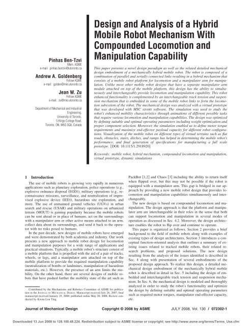
Fig. 1<br />
„a… closed configuration, „b… open configuration, <strong>and</strong> „c… exploded view<br />
platform is limited by the payload capacity <strong>of</strong> the mobile<br />
platform.<br />
Approach to solution. The manipulator arm <strong>and</strong> the mobile<br />
platform are designed <strong>and</strong> packaged as one entity<br />
rather than two separate modules. The mobile platform is<br />
part <strong>of</strong> the manipulator arm, <strong>and</strong> the arm is part <strong>of</strong> the<br />
platform. Yet, the modules are attachable <strong>and</strong> detachable.<br />
The robot links’ interchangeability to provide the functions<br />
<strong>of</strong> the mobile platform <strong>and</strong> manipulator arm requires fewer<br />
components approximately 50% reduction in the number<br />
<strong>of</strong> motors while at the same time the actuator strength<br />
capacity for manipulation purposes increases due to the hybrid<br />
nature <strong>of</strong> the mechanical structure. This approach may<br />
result in a simpler <strong>and</strong> more robust design, significant<br />
weight reduction, higher end-effector payload capability,<br />
<strong>and</strong> lower production cost.<br />
2 Issue. In designs where the mobile robot includes a manipulator<br />
arm, it is mounted <strong>and</strong> folded on top. Therefore,<br />
the arm is exposed to the surroundings <strong>and</strong> hence is susceptible<br />
to breakage <strong>and</strong> damage especially when the mobile<br />
robot is flipped over.<br />
Approach to solution. The arm <strong>and</strong> platform are designed<br />
as one entity, <strong>and</strong> the arm is part <strong>of</strong> the platform. The design<br />
architecture with the arm integrated in the platform<br />
eliminates the exposure to the surroundings when the arm<br />
is folded during motion <strong>of</strong> the mobile platform toward a<br />
target. As soon as the target is reached, the arm is deployed<br />
in order to execute desired tasks.<br />
3 Issue. When operating over rough terrain, robots <strong>of</strong>ten<br />
reach positions from where they could not be righted or<br />
controlled further for a purpose. This requires special purpose<br />
or active means for self-righting in order to restart the<br />
robot’s operation.<br />
Approach to solution. In the new design architecture, the<br />
platform is fully symmetric even with the manipulator arm<br />
integrated, thus it can continue to the target from any situation<br />
with no need <strong>of</strong> additional active means for selfrighting<br />
when it falls or flips over.<br />
4 Description <strong>of</strong> the <strong>Design</strong> Concept<br />
A new design paradigm was introduced in order to address the<br />
design problems mentioned above. The proposed approach is systematic<br />
<strong>and</strong> practical, <strong>and</strong> it addresses the overall system’s operational<br />
performance. The proposed idea is tw<strong>of</strong>old, <strong>and</strong> is described<br />
as follows.<br />
1 The mobile platform <strong>and</strong> the manipulator arm are one entity<br />
rather than two separate <strong>and</strong> attached modules. Moreover,<br />
the mobile platform can be used as part <strong>of</strong> the manipulator<br />
arm <strong>and</strong> vice versa. Thus, some <strong>of</strong> the same joints<br />
motors that provide the manipulator’s DOFs also provide<br />
the platform’s DOFs, <strong>and</strong> vice versa.<br />
2 The robot’s adaptability is enhanced by “allowing” it to flip<br />
over <strong>and</strong> continue to operate instead <strong>of</strong> trying to prevent the<br />
robot from flipping over or attempting to return it selfrighteousness.<br />
When a flipover occurs, due to a fully symmetric<br />
design with the arm integrated, it is only required to<br />
comm<strong>and</strong> the robot to continue to its destination from the<br />
current position. Furthermore, the undesirable effects <strong>of</strong><br />
flipping over or free falling are compensated by a built-in<br />
dual suspension <strong>and</strong> tension mechanism that also allows<br />
effective terrain adaptability.<br />
4.1 Concept Embodiment. To demonstrate the concept, Fig.<br />
1 depicts a possible embodiment <strong>of</strong> the proposed idea. If the platform<br />
is inverted due to flipover, the symmetric nature <strong>of</strong> the design<br />
geometrical shape Fig. 1a allows the platform to continue to<br />
the destination from its new position with no need <strong>of</strong> self-righting.<br />
Also, it is able to deploy/stow the manipulator arm from either<br />
side <strong>of</strong> the platform.<br />
The platform includes two identical base links Link 1 with<br />
tracks left <strong>and</strong> right, Link 2, Link 3, end effector, <strong>and</strong> passive<br />
wheels. To support the symmetric nature <strong>of</strong> the design, all the<br />
links are nested into one another. Link 2 is connected between the<br />
two base link tracks via Joint 1 Fig. 1b. Passive wheels are<br />
inserted between Links 2 <strong>and</strong> 3 <strong>and</strong> connected via Joint 2 <strong>and</strong><br />
another passive wheel is inserted between Link 3 <strong>and</strong> the end<br />
effector via Joint 3 Fig. 1c. The passive wheels are used to<br />
support Links 2 <strong>and</strong> 3 when used for locomotion/traction. The<br />
passive wheels may be actively used for added mobility. Link 2,<br />
Link 3, <strong>and</strong> the end effector are nested into each other to allow<br />
complete symmetry <strong>of</strong> the platform’s geometrical shape. They are<br />
connected through revolute joints <strong>and</strong> are able to provide continuous<br />
360 deg rotation <strong>and</strong> can be deployed separately or together<br />
from either side <strong>of</strong> the platform. To prevent immobilization <strong>of</strong> the<br />
platform during a flipover scenario, rounded <strong>and</strong> pliable covers<br />
are attached to the sides <strong>of</strong> the platform, as shown in Fig. 1a.<br />
The robot’s structure allows it to be scalable <strong>and</strong> can be customized<br />
according to various application needs.<br />
4.2 Modes <strong>of</strong> Operation. The links can be used in three different<br />
modes.<br />
1 All links are used for locomotion to provide added level <strong>of</strong><br />
maneuverability <strong>and</strong> traction.<br />
2 All links are used for manipulation to provide added level<br />
<strong>of</strong> manipulability. The pair <strong>of</strong> base links can provide motion<br />
equivalent to a turret joint <strong>of</strong> the manipulator arm.<br />
3 Combination <strong>of</strong> Modes 1 <strong>and</strong> 2: While some links are used<br />
for locomotion, the rest could be used for manipulation at<br />
the same time, thus the hybrid nature <strong>of</strong> the design<br />
architecture.<br />
All three modes <strong>of</strong> operation are illustrated in Figs. 2–4. In the<br />
proposed design, the motors used to drive the platform for mobility<br />
are also used for the manipulator arm to perform various<br />
tasks since the platform itself is the manipulator <strong>and</strong> vice versa. In<br />
other words, the platform can be used for mobility while at the<br />
same time it can be used as a manipulator arm to perform various<br />
tasks.<br />
4.3 Maneuverability. Figure 2 shows the use <strong>of</strong> Link 2 to<br />
support the platform for enhanced mobility purposes as well as<br />
climbing purposes. Link 2 also helps to prevent the robot from<br />
being immobilized due to high centering, also enables the robot to<br />
Journal <strong>of</strong> Mechanical <strong>Design</strong> JULY 2008, Vol. 130 / 072302-3<br />
Downloaded 13 Jun 2008 to 128.100.48.224. Redistribution subject to ASME license or copyright; see http://www.asme.org/terms/Terms_Use.cfm
Fig. 2 Configurations <strong>of</strong> the mobile platform for mobility<br />
purposes<br />
climb taller objects Fig. 2b, <strong>and</strong> can help propel the robot<br />
forward through continuous rotation. Link 2 is also used to support<br />
the entire platform while moving in a tripod configuration<br />
Fig. 2c. This can be achieved by maintaining a fixed angle<br />
between Links 2 <strong>and</strong> 1 while the tracks are propelling the platform.<br />
Configurations a <strong>and</strong> c in Fig. 2 show two different<br />
possibilities for camera use. Configuration d in Fig. 2 shows the<br />
use <strong>of</strong> Link 3 to surmount an object while Link 2 is used to<br />
support the platform in a tripod structure. The posture <strong>of</strong> the tripod<br />
configuration as shown in Fig. 2c can be switched by rotating<br />
Link 2 in a clockwise direction while passing it between the<br />
Base Link 1 tracks. This functionality is effective when it is necessary<br />
to rapidly switch the robot’s direction <strong>of</strong> motion in a tripod<br />
configuration.<br />
4.4 Manipulation. Figure 3 depicts different modes <strong>of</strong> configuration<br />
<strong>of</strong> the platform for manipulation purposes. While some<br />
links are used as platform for locomotion, others are simultaneously<br />
used for manipulation. Configuration b is similar to configuration<br />
d in terms <strong>of</strong> manipulation capabilities; however, configuration<br />
d is optimal for enhanced traction since the contact<br />
area between the platform <strong>and</strong> the ground is maximized. Configuration<br />
b is useful for increased maneuverability since the contact<br />
area between the platform <strong>and</strong> the ground is minimized. In all<br />
configuration modes for manipulation, while Links 2 <strong>and</strong> 3 are<br />
used for manipulation, the pair <strong>of</strong> base links can provide motion<br />
Fig. 4<br />
Configurations for enhanced traction<br />
equivalent to a turret joint <strong>of</strong> the manipulator arm. Further analysis<br />
on the stability gains <strong>of</strong> each configuration for manipulation as<br />
well as end-effector load capacity analysis <strong>of</strong> each configuration is<br />
discussed in the simulation results presented in Sec. 6.<br />
4.5 Traction. For enhanced traction, Link 2, <strong>and</strong> if necessary<br />
Link 3 can be lowered to the ground level as shown in Figs. 4a<br />
<strong>and</strong> 4b. At the same time, as shown in configuration c, the<br />
articulated nature <strong>of</strong> the mobile platform allows it to be adaptable<br />
to different terrain shapes <strong>and</strong> ground conditions.<br />
4.6 Additional Embodiments <strong>of</strong> the Concept. The main purpose<br />
<strong>of</strong> this section is to show that other possible embodiments <strong>of</strong><br />
the concept may exist as well as to illustrate other locomotion<br />
means that could be used. Therefore, some <strong>of</strong> the design configurations<br />
shown in Fig. 5 may not be exactly realizable as shown.<br />
Figure 5 shows perspective schematic views <strong>of</strong> alternate embodiments<br />
<strong>of</strong> the hybrid mobile robot. Figure 5a shows the robot<br />
without tracks showing it with wheels. Figure 5b shows a perspective<br />
schematic view <strong>of</strong> an alternative hybrid mobile robot<br />
with the right <strong>and</strong> left base links aligned parallel to each other <strong>and</strong><br />
joined at the front <strong>and</strong> back <strong>and</strong> the second link folds by the side<br />
<strong>of</strong> the base links <strong>and</strong> the third link folds inside the second link.<br />
Figure 5c shows a perspective schematic view <strong>of</strong> a further alternative<br />
hybrid mobile robot similar to Fig. 5b except that the<br />
third link folds by the side <strong>of</strong> the second link; <strong>and</strong> Fig. 5d shows<br />
a schematic view <strong>of</strong> a further alternative hybrid mobile robot with<br />
the right <strong>and</strong> left base links aligned parallel to each other <strong>and</strong><br />
joined at the front <strong>and</strong> back, the second link being attached to one<br />
<strong>of</strong> the right <strong>and</strong> left base links, <strong>and</strong> the third link attached to the<br />
other <strong>of</strong> base links. The various configuration modes <strong>of</strong> mobility,<br />
manipulation, <strong>and</strong> traction as described in Figs. 2–4, respectively,<br />
can also be demonstrated by the alternative embodiments as described<br />
in Fig. 5.<br />
Fig. 3<br />
Configuration modes for manipulation<br />
Fig. 5 Additional possible embodiments <strong>of</strong> the design<br />
concept<br />
072302-4 / Vol. 130, JULY 2008 Transactions <strong>of</strong> the ASME<br />
Downloaded 13 Jun 2008 to 128.100.48.224. Redistribution subject to ASME license or copyright; see http://www.asme.org/terms/Terms_Use.cfm
Fig. 6<br />
Deployed-link configuration mode <strong>of</strong> the mobile robot<br />
5 Mechanical <strong>Design</strong> Architecture<br />
This section presents one implementation <strong>of</strong> the design concept<br />
as a case study. The presented case aims at describing the design<br />
structure as well as specific design issues <strong>and</strong> design novelties in<br />
detail. The case study provides a design solution selected from a<br />
range <strong>of</strong> alternatives that are described in Secs. 4.1 <strong>and</strong> 4.6. These<br />
solutions, generated from the conceptual function-oriented analysis,<br />
could be readily used in the development <strong>of</strong> various types <strong>and</strong><br />
configurations <strong>of</strong> robots.<br />
Figure 6 shows the complete mechanical design architecture <strong>of</strong><br />
the mobile robot mechanism with all covers removed. It embodies<br />
the conceptual design architecture described in Sec. 4.1, <strong>and</strong><br />
includes the following design specifications <strong>and</strong> requirements: i<br />
design <strong>and</strong> package the manipulator arm <strong>and</strong> the mobile platform<br />
as one entity rather than two separate mechanisms; ii integrate<br />
the manipulator arm into the platform such that to eliminate its<br />
exposure to the surroundings; iii nest all robot links <strong>and</strong> the<br />
end-effector into each other to allow complete symmetry <strong>of</strong> the<br />
platform’s geometry; iv provide the ability to deploy/stow the<br />
manipulator arm from either side <strong>of</strong> the platform; v integrate<br />
passive wheels into the robot joints in order to support the robot<br />
links when used for locomotion/traction; vi integrate each link<br />
with a revolute joint <strong>and</strong> to be able to provide continuous 360 deg<br />
rotation; vii attach rounded <strong>and</strong> pliable covers to the sides <strong>of</strong> the<br />
platform to prevent immobilization as well as to absorb some <strong>of</strong><br />
the energy resulting from falling or flipping over <strong>of</strong> the robot; <strong>and</strong><br />
viii embed interchangeable track tension <strong>and</strong> suspension mechanism<br />
in the mobile robot base links to form the locomotion subsystem<br />
<strong>of</strong> the robot.<br />
The design includes two identical base link tracks left <strong>and</strong><br />
right, Link 2, Link 3, passive wheels, <strong>and</strong> end-effector mechanism<br />
Fig. 6, Detail A. The two base links have identical orientations<br />
<strong>and</strong> they move together. This is achieved by fixing each <strong>of</strong><br />
the base links to the ends <strong>of</strong> one common shaft. The common<br />
shaft is stationary <strong>and</strong> is located in Joint 1, as shown in Figs. 6 <strong>and</strong><br />
8. To support the symmetric nature <strong>of</strong> the design, all links are<br />
integrated into the platform such that they are nested into one<br />
another. Link 2 is connected between the left <strong>and</strong> right base link<br />
tracks via Joint 1 <strong>and</strong> is rotating about the main common shaft.<br />
Passive wheels are inserted between Links 2 <strong>and</strong> 3 <strong>and</strong> connected<br />
via Joint 2 <strong>and</strong> another passive wheel is inserted between Link 3<br />
<strong>and</strong> the end effector via Joint 3. The design also includes a built-in<br />
dual-operation track tension <strong>and</strong> suspension mechanism situated<br />
in each <strong>of</strong> the base link tracks <strong>and</strong> is described in detail in Sec. 5.3<br />
<strong>and</strong> analyzed <strong>and</strong> simulated in Sec. 6.2. This section describes the<br />
platform drive system, arm joint design <strong>and</strong> integration <strong>of</strong> the arm<br />
into the platform, as well as several specifications <strong>of</strong> the robot<br />
based on a computer-aided design CAD detail design assembly<br />
that was used for the manufacturing <strong>of</strong> the prototype.<br />
Along with the challenge <strong>and</strong> effort to realize the concept into a<br />
feasible, simple, <strong>and</strong> robust design, most <strong>of</strong> the components considered<br />
in this design are <strong>of</strong>f the shelf. The assembly views show<br />
the platform/chassis design <strong>and</strong> the different internal driving<br />
mechanisms along with the description <strong>of</strong> the components used<br />
<strong>and</strong> their function. The closed configuration <strong>of</strong> the robot Fig.<br />
7—all links stowed is symmetric in all directions x, y, <strong>and</strong> z. This<br />
design characteristic is extremely important for significantly enhancing<br />
locomotion ability. As shown in Fig. 7, rounded <strong>and</strong> pliable<br />
side covers are attached on the sides <strong>of</strong> the mobile robot to<br />
prevent immobilization when flipover occurs as well as to absorb<br />
some <strong>of</strong> the energy resulting from falling or flipping over events.<br />
Although the design is fully symmetric, for the purpose <strong>of</strong> explanation<br />
only, the location <strong>of</strong> Joint 1 will be taken as the reference<br />
point, <strong>and</strong> it will be called the front <strong>of</strong> the robot.<br />
5.1 Motor Layout <strong>and</strong> Driving <strong>Mechanism</strong>s. The design includes<br />
four motors situated in the base links <strong>and</strong> two more in the<br />
space available in Link 3 for the gripper mechanism. Of the four<br />
motors located in the base links, two are situated at the back <strong>of</strong><br />
each <strong>of</strong> the base links <strong>and</strong> the other two at the front Fig. 8. All<br />
four motors at the base link tracks are identical Brushless DC<br />
Motors BN34-25EU-02, available from Moog Components<br />
Group with a rated power <strong>of</strong> 363 W <strong>and</strong> a continuous stall torque<br />
<strong>of</strong> 0.7 N m. The motor at the back <strong>of</strong> each base link provides<br />
propulsion to the track attached to that specific base link. The<br />
motion from each motor at the back is transmitted through a 1:32<br />
ratio planetary servo gearhead Series E60, available from Textron<br />
Fluid & Power <strong>and</strong> a 1:2 ratio bevel gear in order to transfer the<br />
motion in a 90 deg angle as well as to amplify the torque capacity<br />
required for propelling the pulleys that drive the tracks. Both mo-<br />
Journal <strong>of</strong> Mechanical <strong>Design</strong> JULY 2008, Vol. 130 / 072302-5<br />
Downloaded 13 Jun 2008 to 128.100.48.224. Redistribution subject to ASME license or copyright; see http://www.asme.org/terms/Terms_Use.cfm
Fig. 7 Stowed-link configuration mode <strong>of</strong> the mobile robot<br />
„top/bottom covers removed…<br />
tors at the back together provide the mobile robot translation <strong>and</strong><br />
orientation in the plane <strong>of</strong> the platform. The motor at the front <strong>of</strong><br />
each base link provides propulsion to one additional link. The<br />
motion is transmitted through a 1:120 ratio harmonic drive CSF-<br />
20-120-2UH, available from Harmonic Drive Systems Inc. <strong>and</strong><br />
two additional transmission stages, namely, a 1:2 ratio bevel transmission<br />
followed by a 1:2.5 ratio chain <strong>and</strong> sprocket transmission<br />
in order to achieve greater torque capacities as required for Links<br />
2 <strong>and</strong> 3 Fig. 8. The motor at the front <strong>of</strong> the right base link<br />
propels Link 2 <strong>and</strong> the motor at the front <strong>of</strong> the left base link<br />
propels Link 3 Figs. 6 <strong>and</strong> 8. The required torque capacities<br />
were derived with the aid <strong>of</strong> the dynamic simulations as described<br />
in detail in Sec. 6, which helped us in selecting appropriate combination<br />
<strong>of</strong> components such as motors <strong>and</strong> gearheads. Each <strong>of</strong> the<br />
motors is equipped with a spring applied break FSBR007, available<br />
from Inertia Dynamics as well as a miniature optical encoder<br />
E4 series, available from US Digital for position <strong>and</strong> velocity<br />
control purposes. The overall location <strong>of</strong> the platform’s COG is an<br />
important characteristic that affects the robot’s tip-over stability.<br />
Therefore, the mechanical structure was derived such that motors<br />
<strong>and</strong> driving mechanisms for the tracks <strong>and</strong> all links are situated at<br />
the base to maintain the entire structure’s COG closer to the<br />
ground.<br />
The gripper mechanism along with its associated electronics<br />
<strong>and</strong> independent power sources are situated in the space available<br />
in Link 3. For the existing design, the gripper has two DOFs <strong>and</strong><br />
hence two additional motors <strong>and</strong> gear systems. As for Links 2 <strong>and</strong><br />
3, the gripper submechanism is integrated such that it can provide<br />
continuous rotations about Joint 3 Fig. 6, Detail A <strong>and</strong> hence can<br />
be deployed from either side <strong>of</strong> Link 3. Rotation about Joint 3 is<br />
generated with a DC Micromotor Series 3557-012C, available<br />
from Faulhaber Group with an output power <strong>of</strong> 14.5 W <strong>and</strong> a<br />
continuous stall torque <strong>of</strong> 115 mN m, connected to a 1:246 ratio<br />
planetary gearhead Series 38/2, available from Faulhaber Group<br />
<strong>and</strong> a 1:3 ratio bevel gear. The open/close motion <strong>of</strong> the gripper is<br />
implemented with a flat brushless DC motor EC45, available<br />
from Maxon Motor with an output power <strong>of</strong> 12 W <strong>and</strong> a nominal<br />
torque <strong>of</strong> 22.8 mN m connected to a miniature 1:100 ratio Harmonic<br />
Drive CSF-Mini Series Type 2XH-J, available from Harmonic<br />
Drive Systems Inc. <strong>and</strong> a 1:30 ratio worm gear Fig. 8.<br />
5.2 Base Link 1 Tracks. The right <strong>and</strong> left base link tracks<br />
are each symmetric in all directions x, y, <strong>and</strong> z <strong>and</strong> identical in<br />
terms <strong>of</strong> the internal driving mechanisms although the mechanisms<br />
situated at the front each drives a different link.<br />
In the center <strong>of</strong> each track, there is a solid self-tracking rib that<br />
fits into a guide located at the center <strong>of</strong> the main pulleys outer rim,<br />
as well as on all six planetary supporting pulleys, as shown in Fig.<br />
9. This feature prevents the track from laterally sliding <strong>of</strong>f, thus<br />
preventing the tracks from coming <strong>of</strong>f the pulleys. In addition to<br />
the motors, as described in Sec. 5.1, all electrical hardware such<br />
as batteries, controllers, drivers, electrical boxes, sensor boxes,<br />
Audio/Video <strong>and</strong> Data RF cards, gearheads, etc. are situated in<br />
the left <strong>and</strong> right base link tracks. Other motors <strong>and</strong> associated<br />
electrical hardware for the gripper mechanism are situated in the<br />
space available in Link 3.<br />
Fig. 8<br />
Open configuration mode <strong>and</strong> general dimensions „front <strong>and</strong> top views—all covers removed…<br />
072302-6 / Vol. 130, JULY 2008 Transactions <strong>of</strong> the ASME<br />
Downloaded 13 Jun 2008 to 128.100.48.224. Redistribution subject to ASME license or copyright; see http://www.asme.org/terms/Terms_Use.cfm
Table 1<br />
<strong>Robot</strong> design specifications<br />
Total estimated weight<br />
including batteries <strong>and</strong> electronics<br />
Length arm stowed<br />
Length arm deployed<br />
Width with pliable side covers<br />
Height arm stowed<br />
65 kg<br />
814 mm<br />
2034 mm<br />
626 mm<br />
179 mm<br />
Fig. 9 Isometric view <strong>of</strong> base link track showing internal pulley<br />
arrangement<br />
Other accessories typically found in mobile robots such as cameras,<br />
lights, <strong>and</strong> antennas are embedded in the platform. In other<br />
designs <strong>of</strong> mobile robots, these items typically stick out or protrude<br />
from the platform. In order to prevent their exposure to the<br />
surrounding <strong>and</strong> thereby eliminate risk <strong>of</strong> damage in cases were<br />
the robot flips over or falls, the charge-coupled device CCD<br />
cameras <strong>and</strong> light-emitting diode LED lights were embedded in<br />
the front <strong>and</strong> back <strong>of</strong> the left <strong>and</strong> right base link tracks, respectively,<br />
as shown in Fig. 7 <strong>and</strong> the top view in Fig. 8. Two special<br />
flat antennas are embedded in the right <strong>and</strong> left side covers for<br />
Data RF signals <strong>and</strong> Audio/Video RF signals, respectively Fig.<br />
7. The flat shape <strong>of</strong> the antennas <strong>and</strong> their location in the side<br />
covers maintain the symmetric nature <strong>of</strong> the entire hybrid platform<br />
<strong>and</strong> minimize the chance for loss <strong>of</strong> data or breakage <strong>of</strong> the<br />
antenna if it were to protrude vertically up.<br />
5.3 Built-In Dual-Operation Track Tension <strong>and</strong> Suspension<br />
<strong>Mechanism</strong>. The arrangement <strong>of</strong> the supporting planetary<br />
pulleys is shown in Fig. 9. Each <strong>of</strong> the supporting pulleys is<br />
mounted on a supporting bar Fig. 9 that is connected at each end<br />
to a compression spring Fig. 6, Detail B. The ends <strong>of</strong> each supporting<br />
bar are guided through a groove on either side <strong>of</strong> the base<br />
link as shown in Detail B <strong>of</strong> Fig. 6. Therefore, each set <strong>of</strong> three<br />
planetary pulleys in the top <strong>and</strong> bottom <strong>of</strong> the left <strong>and</strong> right base<br />
link tracks is suspended by a 23 spring array. The purpose <strong>of</strong><br />
the supporting pulleys is dual <strong>and</strong> provides two very important<br />
functions. While the bottom three supporting pulleys in each base<br />
link are in contact with the ground, they act as a suspension system.<br />
At the same time, the upper three supporting pulleys will<br />
provide a predetermined tension in the tracking system, as shown<br />
in Fig. 10. This dual operation track suspension <strong>and</strong> tension<br />
mechanism accounts for the symmetric nature <strong>of</strong> the design <strong>and</strong><br />
operation <strong>of</strong> the mobile robot. In other words, if the platform is<br />
inverted, the three supporting pulleys that were used as suspension<br />
will act to maintain the tension in the tracks, while the other three<br />
pulleys that were used to provide tension in the tracks will act as<br />
a suspension system. The required tension in the track belt <strong>and</strong> the<br />
suspension stroke can be preset by fastening or loosening the<br />
compression nuts Fig. 6, Detail B. Another usage <strong>of</strong> the spring<br />
array is to absorb some energy resulting from falling or flipping,<br />
thus providing compliance to impact forces. Further discussion<br />
<strong>and</strong> analysis <strong>of</strong> this mechanism are provided in Sec. 6.2.<br />
General design specifications <strong>of</strong> the robot are provided in Table<br />
1. Photos <strong>of</strong> the hybrid mobile robot physical prototype in the<br />
close <strong>and</strong> open configurations are shown in Figs. 11a <strong>and</strong> 11b.<br />
In order to support the reported mobility <strong>of</strong> this robot, a photo<br />
showing the prototype in the configuration illustrated in Fig.<br />
13a2 is shown in Fig. 11c.<br />
5.4 <strong>Robot</strong> Degrees <strong>of</strong> Freedom Coordination. The remote<br />
operating control unit OCU includes two control sticks in order<br />
to coordinate the robot degrees <strong>of</strong> freedom when generating the<br />
motions required for a given task. Of the four motors located in<br />
the base links, two are situated at the back <strong>of</strong> each <strong>of</strong> the base<br />
links <strong>and</strong> the other two at the front Fig. 8. The motor at the back<br />
<strong>of</strong> each base link provides propulsion to the track attached to that<br />
specific base link. Both motors at the back together provide the<br />
mobile robot translation <strong>and</strong> orientation in the plane <strong>of</strong> the platform.<br />
The motor at the front <strong>of</strong> the right base link propels Link 2<br />
<strong>and</strong> the motor at the front <strong>of</strong> the left base link propels Link 3<br />
Figs. 6 <strong>and</strong> 8. For the existing design, the gripper mechanism<br />
has two DOFs <strong>and</strong> hence two additional motors are located in the<br />
system.<br />
The forward, backward, right turn, <strong>and</strong> left turn motions <strong>of</strong> the<br />
base link tracks are controlled by up, down, right, <strong>and</strong> left movements<br />
<strong>of</strong> the first control stick. The second control stick is used to<br />
control Links 2 <strong>and</strong> 3 degrees <strong>of</strong> freedom. A right movement <strong>of</strong><br />
this control stick will generate a clockwise CW independent<br />
motion <strong>of</strong> Link 2 while a left movement <strong>of</strong> the stick will generate<br />
a counterclockwise CCW independent motion <strong>of</strong> Link 2. Simi-<br />
Fig. 10 Side view <strong>of</strong> base link track showing general pulley<br />
arrangement <strong>and</strong> track tension/suspension mechanism<br />
Fig. 11 A photo <strong>of</strong> the physical prototype: „a… stowed-link configuration<br />
mode, „b… open configuration mode, <strong>and</strong> „c… <strong>and</strong> „d…<br />
cylinder climbing configuration<br />
Journal <strong>of</strong> Mechanical <strong>Design</strong> JULY 2008, Vol. 130 / 072302-7<br />
Downloaded 13 Jun 2008 to 128.100.48.224. Redistribution subject to ASME license or copyright; see http://www.asme.org/terms/Terms_Use.cfm
as specified in Table 2. The control angle in C2 provides speed<br />
variability to each <strong>of</strong> Links 2 <strong>and</strong> 3 when simultaneously operated.<br />
Fig. 12 „a… Control Stick No. 1 „C1… motion layout; „b… Control<br />
Stick No. 2 „C2… motion layout<br />
larly, an up <strong>and</strong> down movement <strong>of</strong> the second control stick will<br />
generate an independent CW <strong>and</strong> CW motion <strong>of</strong> Link 3, respectively.<br />
Furthermore, four diagonal movements <strong>of</strong> the second control<br />
stick i.e., +x, −x, +y, −y directions as shown in Fig.<br />
12b will generate simultaneous motions <strong>of</strong> Links 2 <strong>and</strong> 3 as<br />
follows.<br />
i Movement <strong>of</strong> the control stick in the +x direction will<br />
simultaneously move both Links 2 <strong>and</strong> 3 in the CW direction.<br />
ii Movement <strong>of</strong> the control stick in the −x direction will<br />
simultaneously move both Links 2 <strong>and</strong> 3 in the CCW direction.<br />
iii Movement <strong>of</strong> the control stick in the +y direction will<br />
simultaneously move both Links 2 <strong>and</strong> 3 in the CW <strong>and</strong><br />
CCW directions, respectively.<br />
iv Movement <strong>of</strong> the control stick in the −y direction will<br />
simultaneously move both Links 2 <strong>and</strong> 3 in the CCW <strong>and</strong><br />
CW directions, respectively.<br />
The CW <strong>and</strong> CCW wrist motions <strong>of</strong> the gripper mechanism as<br />
well as the open <strong>and</strong> close motions <strong>of</strong> the gripper jaws are generated<br />
with a separate mode <strong>of</strong> the first control stick.<br />
The first <strong>and</strong> second control sticks can be simultaneously operated<br />
by the operator in order to provide simultaneous motions <strong>of</strong><br />
the tracks along with different motion combinations <strong>of</strong> Links 2<br />
<strong>and</strong> 3, as explained above.<br />
The above motion procedures are summarized in Fig. 12 <strong>and</strong><br />
Table 2. Figure 12a shows the top view <strong>of</strong> Control Stick No. 1<br />
C1 with two switchable states as follows: i track motions—<br />
State 1 S1; <strong>and</strong> ii gripper mechanism motions—State 2 S2.<br />
Figure 12b shows the top view <strong>of</strong> Control Stick No. 2 C2 with<br />
two coordinate systems x-y <strong>and</strong> x-y for Links 2 <strong>and</strong> 3 motions,<br />
Tracks<br />
motions<br />
Gripper<br />
Table 2<br />
<strong>Robot</strong> motion specifications<br />
FWD BWD Right Left<br />
C1+S1<br />
+y H/L<br />
Wrist<br />
CW<br />
C1+S2<br />
+y<br />
C1+S1<br />
−y H/L<br />
Wrist<br />
CCW<br />
C1+S2<br />
−y<br />
C1+S1<br />
+x H/L<br />
Gripper<br />
jaws<br />
open<br />
C1+S2<br />
+z<br />
C1+S1<br />
−x H/L<br />
Gripper<br />
jaws<br />
close<br />
C1+S2<br />
−z<br />
CW CCW CW/CCW CCW/CW<br />
Link 2 alone C2 +x C2 −x N/A N/A<br />
Link 3 alone C2 +y C2 +y N/A N/A<br />
Links 2+3 C2 +x C2 −x C2 +y C2 −y<br />
6 Modeling <strong>and</strong> Dynamic Simulations <strong>of</strong> the <strong>Hybrid</strong><br />
<strong>Robot</strong>ic System<br />
Dynamic simulations <strong>of</strong> the complete robotic system were performed<br />
in order to study its functionality <strong>and</strong> demonstrate its expected<br />
capability for design optimization purposes. The 3D mechanical<br />
design assembly that was developed with a CAD s<strong>of</strong>tware<br />
was exported to <strong>and</strong> modeled in ADAMS s<strong>of</strong>tware to perform motion<br />
simulations. The simulation experiments are accounting for<br />
the mass distribution <strong>of</strong> the robot including batteries, motors,<br />
electronics, etc., inertia properties <strong>and</strong> acceleration <strong>of</strong> the links,<br />
as well as contact <strong>and</strong> friction forces between the links <strong>and</strong> tracks<br />
<strong>and</strong> the ground.<br />
When designing a mechanical system such as this hybrid robot,<br />
it was required to underst<strong>and</strong> how various components interact as<br />
well as what forces those components generate during operation.<br />
We used ADAMS, commercial motion simulation s<strong>of</strong>tware, to analyze<br />
the behavior <strong>of</strong> the entire robotic mechanical system. It allowed<br />
us to test virtual prototypes <strong>and</strong> optimize designs for performance,<br />
without having to build <strong>and</strong> test several physical<br />
prototypes. This dramatically reduced our prototype development<br />
time <strong>and</strong> cost.<br />
The simulations enabled us to visualize <strong>and</strong> validate various<br />
robot mobility cases to study its functionality <strong>and</strong> hence optimize<br />
the design. The design optimization process involved weight distribution<br />
optimization, proper component selection e.g., springs<br />
for track tension/suspension, motors, <strong>and</strong> gear ratios, etc. Weight<br />
distribution optimization was performed by identifying the optimal<br />
weight <strong>of</strong> each robot link base links, Link 2, <strong>and</strong> Link 3<br />
such that the robot’s posture remained stable tip-over stability<br />
during the motion <strong>of</strong> the robot links while performing various<br />
locomotion <strong>and</strong> manipulation tasks. This was done by visualizing<br />
each task with the aid <strong>of</strong> the animations, as described in detail in<br />
Sec. 6.1, <strong>and</strong> changing the weight <strong>of</strong> each link as necessary until<br />
a stable posture was observed during the entire range <strong>of</strong> the link<br />
motion for a particular task. This procedure was repeated for several<br />
locomotion <strong>and</strong> manipulations tasks, as described in Secs. 6.1<br />
<strong>and</strong> 6.4, respectively, until a common optimal combination <strong>of</strong> link<br />
weights was identified. The requisite for a flexible dynamics capability<br />
for the track system was addressed with ADAMS tracked<br />
vehicle ATV toolkit. A modus oper<strong>and</strong>i using ADAMS <strong>and</strong> ATV<br />
toolkit was developed <strong>and</strong> used to model the tracks 52,53.<br />
The data pertaining to each simulation performed were processed<br />
for the following specific major purposes that will be discussed<br />
in detail in subsequent subsections: i study the robot’s<br />
mobility characteristics through animations <strong>of</strong> different possible<br />
tasks that require various locomotion <strong>and</strong> manipulation capabilities,<br />
ii analyze the suspension <strong>and</strong> track tension retention by<br />
examining the spring array force distributions, iii define each<br />
joint’s torque requirements for different mobility tasks <strong>and</strong> select<br />
proper gear ratios <strong>and</strong> motors, <strong>and</strong> iv define maximum endeffector<br />
payload capacity for different robot configurations. Different<br />
types <strong>of</strong> terrains such as flat roads, obstacles, stairs, ditches,<br />
<strong>and</strong> ramps were created in a manner such that they could be easily<br />
changed according to different size <strong>and</strong> shape requirements.<br />
6.1 Mobility Characteristics <strong>Analysis</strong>: Animation Results.<br />
To study the robot’s functionality, the following simulations were<br />
performed: various manipulation scenarios all three modes <strong>of</strong> operation<br />
as described in Sec. 4.2, r<strong>and</strong>om rotations <strong>of</strong> all links,<br />
traversing pipes <strong>of</strong> different diameters, climbing <strong>and</strong> descending<br />
rectangular obstacles with different link configurations, crossing<br />
ditches with different gap dimensions, climbing <strong>and</strong> descending<br />
stairs, flipping over due to a ramp obstacle, lifting tasks, <strong>and</strong><br />
more. To illustrate, few <strong>of</strong> the above mentioned animation results<br />
072302-8 / Vol. 130, JULY 2008 Transactions <strong>of</strong> the ASME<br />
Downloaded 13 Jun 2008 to 128.100.48.224. Redistribution subject to ASME license or copyright; see http://www.asme.org/terms/Terms_Use.cfm
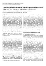
Fig. 13 Animation results: „a… surmounting cylindrical obstacles, „b… stair climbing, „c… stair descending, „d… step climbing<br />
with tracks, „e… step climbing with Link 2, „f… step descending, <strong>and</strong> „g… ditch crossing<br />
are presented in Fig. 13. Each <strong>of</strong> the subfigures a–g represents<br />
several configuration steps 1–5 or motions that the different<br />
links along with the tracks need to undergo in order to accomplish<br />
each task or specific functionality. They are discussed as follows.<br />
Surmounting cylindrical obstacles (Fig. 13(a)). The segmented<br />
<strong>and</strong> articulated nature <strong>of</strong> the robot’s structure allows it to surmount<br />
large cylindrical obstacles such as pipes <strong>and</strong> tree logs with<br />
at least 0.4 m diameter. The base link tracks are deployed until<br />
they touch the obstacle a1–3; at that point, the tracks propel<br />
the platform a3 while at the same time they continue to rotate<br />
about Joint 1 a4–5.<br />
Stair climbing (Fig. 13(b)). The base link tracks are first deployed<br />
until they touch the stairs b2; Link 2 is closed <strong>and</strong> the<br />
robot starts climbing with tracks b3; at the end <strong>of</strong> the stairs,<br />
Link 3 opens b4 to support the platform while the robot is in<br />
motion until configuration b5; Link 3 rotates until stowed between<br />
tracks to lower the robot until the tracks fully contact the<br />
ground. Stairs with various raiser/run dimensions can be climbed<br />
<strong>and</strong> descended.<br />
Stair descending (Fig. 13(c)). Link 2 is deployed until it<br />
touches the stairs c2; the robot advances until the entire platform<br />
is on the stairs c3; Link 2 closes c4; <strong>and</strong> the platform<br />
descends the stairs c5.<br />
Step climbing with tracks (Fig. 13(d)). The base link tracks are<br />
first deployed on the step d2; Link 2 continues to rotate until<br />
the base link tracks adjust with the pr<strong>of</strong>ile <strong>of</strong> the terrain d3; the<br />
platform advances to accomplish the climbing process d4 <strong>and</strong><br />
Link 2 closes d5. This climbing can also be accomplished with<br />
Link 3 by interchanging the roles <strong>of</strong> Links 2 <strong>and</strong> 3 in this case,<br />
the back <strong>of</strong> the robot will be facing the step obstacle. Step heights<br />
<strong>of</strong> at least 0.5 m could be climbed <strong>and</strong> descended.<br />
Journal <strong>of</strong> Mechanical <strong>Design</strong> JULY 2008, Vol. 130 / 072302-9<br />
Downloaded 13 Jun 2008 to 128.100.48.224. Redistribution subject to ASME license or copyright; see http://www.asme.org/terms/Terms_Use.cfm
Fig. 14<br />
Flipover scenario<br />
Step climbing with Link 2 (Fig. 13(e)). This figure shows a<br />
series <strong>of</strong> configurations the robot needs to undergo in order to<br />
climb the step obstacle with Link 2 while Link 3 is deployed from<br />
the back to support the entire platform to complete the climbing<br />
process. This climbing can also be achieved with Link 3 by interchanging<br />
the roles <strong>of</strong> Links 2 <strong>and</strong> 3 in this case, the back <strong>of</strong> the<br />
robot will be facing the step obstacle.<br />
Step descending (Fig. 13(f)). Link 2 is deployed until it touches<br />
the ground to support the robot when advancing f2, Link 2<br />
rotates to lower the front <strong>of</strong> the platform f3; Link 2 fully closes<br />
f4; Link 3 opens to support the robot when moved forward e;<br />
Link 3 rotates until closed to lower the robot until the tracks fully<br />
contact the ground.<br />
Ditch crossing (Fig. 13(g)). Since the robot can deploy Link 2<br />
from the front <strong>and</strong> Link 3 from the back when all links are<br />
stowed, ditches up to 0.635 m in width can be easily traversed<br />
according to the following steps: from the back edge <strong>of</strong> the ditch,<br />
Link 2 is deployed g1; the robot advanced until the front <strong>and</strong><br />
back pulleys are supported by the ditch edges g2; Link 2 closes<br />
<strong>and</strong> Link 3 opens from the back g3; the robot continues its<br />
forward motion until the COG passes the front edge <strong>of</strong> the ditch<br />
while Link 3 prevents from the robot from falling into the ditch as<br />
long as the COG is before the front edge g4–5.<br />
The fully symmetric structure <strong>of</strong> the mobile robot along with its<br />
ability to sustain some forces resulting from falling or flipping<br />
over due to its track suspension system <strong>and</strong> pliable rounded<br />
sides can allow it to accomplish a mission requiring manipulation<br />
capabilities in spite <strong>of</strong> the fact that the robot flips over or falls due<br />
to an obstacle the robot could not avoid. Figure 14 shows several<br />
snapshots <strong>of</strong> a simulation showing a robot stowing its links before<br />
flipping over occurs <strong>and</strong> deploying them again from the other side<br />
<strong>of</strong> the platform after the robot flipped over.<br />
6.2 <strong>Analysis</strong> <strong>of</strong> Track Tension <strong>and</strong> Suspension <strong>Mechanism</strong>.<br />
These analyses aided in finding the optimal spring stiffness value<br />
for the dual tension-suspension mechanism. This was performed<br />
by visualizing the spring compression/expansion with different<br />
stiffness values to verify that it meets the allowable displacements<br />
for track tension <strong>and</strong> suspension purposes.<br />
The graphs in Fig. 15 represent the force in each spring in the<br />
top <strong>and</strong> bottom spring arrays on each side <strong>of</strong> the platform due to<br />
symmetry, each graph represents the force <strong>of</strong> the right <strong>and</strong> left<br />
springs in each base link. While the bottom supporting springs in<br />
each track contact the ground, they act as a suspension system for<br />
the platform. At the same time, the upper supporting springs exert<br />
forces upwards to maintain a predetermined tension in the track<br />
system. To illustrate this, Fig. 15 represents simulation results <strong>of</strong><br />
the robot surmounting a small obstacle 34 cm 2 to observe<br />
how the springs react to obstacles situated between the planetary<br />
pulleys.<br />
Fig. 15<br />
Top „„a…—track tension… <strong>and</strong> bottom „„b…—suspension… spring array force distribution<br />
072302-10 / Vol. 130, JULY 2008 Transactions <strong>of</strong> the ASME<br />
Downloaded 13 Jun 2008 to 128.100.48.224. Redistribution subject to ASME license or copyright; see http://www.asme.org/terms/Terms_Use.cfm
Fig. 17 Driving pulley motor torque requirement—inclined<br />
condition<br />
Fig. 16 Link 2 motor torque requirement—step obstacle<br />
climbing with tracks „via Joint 1…<br />
From the top spring array force distribution Fig. 15a, we<br />
observe that the average force in each spring is constant as expected<br />
since they support only the part <strong>of</strong> the track that does not<br />
touch the ground. In this case, the springs act to retain tension in<br />
the track. Also, the forces in the springs supporting the middle<br />
planetary pulley are generally smaller than those located <strong>of</strong>f center,<br />
which is in agreement with the track shape characteristics due<br />
to its bending. Namely, the springs in the center are less compressed<br />
than those <strong>of</strong>f center <strong>and</strong> hence generate less force. The<br />
forces are in the range 0–40 N as the installation compression <strong>of</strong><br />
each spring was 8 mm <strong>and</strong> the optimal spring constant was found<br />
to be 5.19 N/mm.<br />
From the bottom spring array force distribution Fig. 15b, the<br />
force in each spring is fluctuating as expected since it supports the<br />
part <strong>of</strong> the track that touches the ground <strong>and</strong> hence in direct contact<br />
with the obstacle. The forces in all bottom springs are generally<br />
<strong>of</strong> equal range <strong>of</strong> magnitude since none <strong>of</strong> these springs are<br />
free to exp<strong>and</strong> according only with the tracks pliability. In this<br />
case, the forces are greater than 40 N since the springs are compressed<br />
more than the installation compression value due to the<br />
ground’s shape irregularities, which exert additional external<br />
forces on the tracks.<br />
6.3 <strong>Analysis</strong> <strong>of</strong> Motor Torque Requirements. This section<br />
outlines the results <strong>of</strong> additional dynamic simulations performed<br />
in order to calculate the torque required in Joints T 1 , T 2 , <strong>and</strong> T 3<br />
Fig. 8 to propel the tracks, Link 2, <strong>and</strong> Link 3, respectively, for<br />
various mobility scenarios. Once the maximum torque requirement<br />
for each joint was evaluated, proper gear ratios <strong>and</strong> motors<br />
were selected.<br />
Practically, the harshest operating conditions for each motor<br />
will dictate the motor’s selection criteria. An analysis is performed<br />
for each motor in the system by generating torque plots for several<br />
mobility scenarios that require the largest torque capacity. Based<br />
on those torque plots, the maximum peak torque <strong>and</strong> its occurrence<br />
in a given range <strong>of</strong> motion are identified. The peak torque<br />
values define the maximum torque capacity necessary for each<br />
joint.<br />
Figure 16 shows a series <strong>of</strong> motions the different links <strong>and</strong> the<br />
tracks need to undergo in order to climb a 0.5 m step height with<br />
the base link tracks <strong>and</strong> the torque required at every step <strong>of</strong> the<br />
motion. The angular velocity <strong>of</strong> Link 2 30 deg/s was used to<br />
identify the torque at every step <strong>of</strong> the motion with respect to the<br />
angle traveled by the link. According to the torque plot, the torque<br />
peak value for this case occurs at the beginning <strong>of</strong> the motion<br />
T 2 =141.2 N m at t=0. In another analysis similar to Fig. 16, if<br />
the climbing is performed with Link 2 steps shown in Fig. 13e,<br />
a maximum torque value <strong>of</strong> T 2 =141.7 N m was required.<br />
Similar torque analysis procedure was performed to obtain Link<br />
3 motor torque requirement Joint 2 for different scenarios <strong>and</strong><br />
was found to be T 3 =157 N m. For symmetry reasons, we defined<br />
T 2 =T 3 when selecting the motors <strong>and</strong> driving mechanisms for<br />
Links 2 <strong>and</strong> 3. In order to be able to generate the required torques,<br />
Lithium-ion batteries with high drain current capabilities as well<br />
as proper harmonic gearheads <strong>and</strong> brushless DC motors were incorporated<br />
in the design.<br />
When the robot moves on a flat ground or a slope, the driving<br />
torque T 1 Fig. 17 for a single track is determined based on the<br />
condition that slipping does not occur. Therefore, static friction<br />
coefficients were used to estimate the required driving force.<br />
Equation 1 is used in order to estimate the driving force for a<br />
single track. Practically, vibrations <strong>and</strong> impacts occur in the driving<br />
system <strong>and</strong> there are r<strong>and</strong> noises in real-time values <strong>of</strong> F D .<br />
F D s N + W 2 sin = W 2 s cos + sin <br />
To ensure incline motion conditions, the expression to estimate<br />
the torque can be written as follows:<br />
T 1 WR<br />
2 s cos + sin <br />
1<br />
gear k gear track<br />
where F D is the driving force <strong>of</strong> a single track friction force, R is<br />
the outer radii <strong>of</strong> the track, W is the total weight, s is the coefficient<br />
<strong>of</strong> static friction, gear is gear efficiency, k gear is gear ratio<br />
input to output rotational speeds, <strong>and</strong> track is track efficiency.<br />
6.4 End-Effector Payload Capacity <strong>Analysis</strong>. The purpose<br />
<strong>of</strong> this simulation was to identify the maximum allowable endeffector<br />
load capacity <strong>of</strong> the platform with respect to various configurations<br />
by examining the COG vertical movement with respect<br />
to the ground, which indicates tip-over stability. The graph shown<br />
in Fig. 18 describes the change in the robot’s COG position in the<br />
vertical direction with respect to linearly increasing load applied<br />
at the end effector. Among several simulation results based on<br />
various configurations, one possible optimal configuration for this<br />
purpose is shown in Fig. 18. The maximum end-effector load<br />
capacity was found at the instant when the COG position is<br />
greater than zero dashed line in Fig. 18 graph, which indicates<br />
that the COG <strong>of</strong> the robot starts to move up vertically. According<br />
to the graph, the static load capacity with this configuration is<br />
77 kg. Practically, the maximum allowable torque capacity <strong>of</strong><br />
Joints 1 <strong>and</strong> 2 will restrict the actual end-effector load capacity.<br />
Possible selected configurations for manipulation are schematically<br />
presented in Fig. 19. Among the configurations shown in this<br />
figure, some other configurations can be generated in the range <strong>of</strong><br />
the configurations shown, such as vertical or horizontal reach. For<br />
a given torque capacity in Joint 1, configuration c is optimal for<br />
maximum load capacity W p due to its greater tip-over stability. In<br />
each <strong>of</strong> the configurations b, d, <strong>and</strong> e depending on required<br />
level <strong>of</strong> mobility, an end-effector load <strong>of</strong> 18.3 kg is expected<br />
with 157 N m torque capacity in Joints 1 <strong>and</strong> 2. This result is a<br />
direct consequence <strong>of</strong> the novel design architecture, namely, the<br />
1<br />
2<br />
Journal <strong>of</strong> Mechanical <strong>Design</strong> JULY 2008, Vol. 130 / 072302-11<br />
Downloaded 13 Jun 2008 to 128.100.48.224. Redistribution subject to ASME license or copyright; see http://www.asme.org/terms/Terms_Use.cfm
Fig. 18<br />
Platform COG versus load capacity<br />
hybrid nature <strong>of</strong> the platform <strong>and</strong> manipulator arm <strong>and</strong> their ability<br />
to be interchangeable in their roles.<br />
Fig. 19<br />
Possible configurations for manipulation<br />
7 Conclusion<br />
The new mobile robot mechanical design paradigm presented in<br />
this paper was based on hybridization <strong>of</strong> the mobile platform <strong>and</strong><br />
manipulator arm as one entity for robot locomotion as well as<br />
manipulation. The novel design was derived based on a conceptual<br />
function-oriented analysis, which addressed <strong>and</strong> summarized<br />
major issues <strong>of</strong> mobile robots in field operations. This design approach<br />
along with other design novelties <strong>and</strong> characteristics inherent<br />
to the robot presented provide solutions to various issues related<br />
to design <strong>of</strong> mobile robots operating on rough terrain <strong>and</strong> in<br />
hazardous environments as well as in man-made urbanized indoor<br />
<strong>and</strong> outdoor environments. The proposed approach is a systematic<br />
<strong>and</strong> practical design <strong>and</strong> development method that addressed the<br />
overall system’s operational performance. These contributions toward<br />
the design approach should not only improve the designers’<br />
view <strong>of</strong> the design problem, but also allow novel design concepts<br />
with potentially better configurations. To model <strong>and</strong> analyze the<br />
overall robotic system, a virtual prototype was developed in AD-<br />
AMS for multibody dynamic motion simulations <strong>of</strong> the complete<br />
robotic system. This has considerably reduced the prototype development<br />
time <strong>and</strong> cost while aiding with demonstrating the robot’s<br />
expected functionality for design optimization purposes <strong>and</strong><br />
derivation <strong>of</strong> optimal operating parameters. The derived parameters<br />
were used in the design <strong>and</strong> construction <strong>of</strong> a physical prototype.<br />
Acknowledgments<br />
This work was partially supported by Natural Sciences <strong>and</strong> Engineering<br />
Research Council <strong>of</strong> Canada NSERC, grants held by<br />
Pr<strong>of</strong>essor Andrew A. Goldenberg <strong>and</strong> Pr<strong>of</strong>essor Jean W. Zu.<br />
References<br />
1 Yamauchi, B., 2004, “PackBot: A Versatile Platform for Military <strong>Robot</strong>ics,”<br />
Proc. SPIE, 5422, pp. 228–237.<br />
2 Frost, T., Norman, C., Pratt, S., <strong>and</strong> Yamauchi, B., 2002, “Derived Performance<br />
Metrics <strong>and</strong> Measurements Compared to Field Experience for the Pack-<br />
Bot,” in Proceedings <strong>of</strong> the 2002 PerMIS Workshop, Gaithersburg, MD.<br />
3 Lewis, P. J., Flann, N., Torrie, M. R., Poulson, E. A., Petr<strong>of</strong>f, T., <strong>and</strong> Witus, G.,<br />
2005, “Chaos: An Intelligent Ultra-<strong>Mobile</strong> SUGV: Combining the Mobility <strong>of</strong><br />
Wheels, Tracks, <strong>and</strong> Legs,” Proc. SPIE, 5804, pp. 427–438.<br />
4 Carlson, J., <strong>and</strong> Murphy, R. R., 2005, “How UGVs Physically Fail in the<br />
Field,” IEEE Trans. Rob. Autom., 213, pp. 423–437.<br />
5 Murphy, R. R., 2004, “Activities <strong>of</strong> the Rescue <strong>Robot</strong>s at the World Trade<br />
Center From 11–21 September 2001,” IEEE Rob. Autom. Mag., 113, pp.<br />
50–61.<br />
6 White, J. R., Sunagawa, T., <strong>and</strong> Nakajima, T., 1989, “Hazardous-Duty<br />
<strong>Robot</strong>s—Experiences <strong>and</strong> Needs,” Proceedings <strong>of</strong> the IEEE/RSJ International<br />
Workshop on Intelligent <strong>Robot</strong>s <strong>and</strong> Systems ’89 IROS ’89, pp. 262–267.<br />
7 White, J. R., Coughlan, J., Harvey, M., Upton, R., <strong>and</strong> Waer, K., 1989, “Taking<br />
Andros for a Walk,” Nucl. Eng. Int., 34415, pp. 52–53.<br />
8 Martens, J. D., <strong>and</strong> Newman, W. S., 1994, “Stabilization <strong>of</strong> a <strong>Mobile</strong> <strong>Robot</strong><br />
Climbing Stairs,” in Proceedings <strong>of</strong> the IEEE International Conference on<br />
<strong>Robot</strong>ics <strong>and</strong> Automation, San Diego, CA, Vol. 3, pp. 2501–2507.<br />
9 Goldenberg, A. A., <strong>and</strong> Lin, J., 2005, “Variable Configuration Articulated<br />
Tracked Vehicle,” U.S. Patent No. 11/196,486.<br />
10 TALON <strong>Mobile</strong> <strong>Robot</strong>, Foster-Miller. Available: http://www.foster-miller.com/<br />
lemming.htm.<br />
11 Gladiator <strong>Mobile</strong> <strong>Robot</strong>, <strong>Robot</strong>ics institute, available: http://www.ri.cmu.edu.<br />
12 S<strong>and</strong>ia National Laboratories, available: http://www.s<strong>and</strong>ia.gov.<br />
13 MR-7 Tracked <strong>Mobile</strong> <strong>Robot</strong>, available: www.esit.com.<br />
14 Bares, J., <strong>and</strong> Stager, D., 2004, “Exp<strong>and</strong>ed Field Testing Results From Spinner:<br />
A High Mobility <strong>Hybrid</strong> UGCV,” Proceedings <strong>of</strong> the AUVSI Unmanned<br />
Systems 2004 Conference, Anaheim, CA.<br />
15 Drenner, A., Burt, I., Dahlin, T., Kratochvil, B., McMillen, C. P., Nelson, B.,<br />
Papanikolopoulos, N., Rybski, P. E., Stubbs, K., Waletzko, D., <strong>and</strong> Yesin, K.<br />
B., 2002, “Mobility Enhancements to the Scout <strong>Robot</strong> Platform,” Proceedings<br />
<strong>of</strong> the 2002 IEEE International Conference on <strong>Robot</strong>ics <strong>and</strong> Automation,<br />
Washington, DC, pp. 1069–1074.<br />
16 Drenner, A., Burt, I., Kratochvil, B., Nelson, B., Papanikolopoulos, N., <strong>and</strong><br />
Yesin, K. B., 2002, “Communication <strong>and</strong> Mobility Enhancements to the Scout<br />
<strong>Robot</strong>,” Proceedings <strong>of</strong> the 2002 IEEE/RSJ International Conference on Intelligent<br />
<strong>Robot</strong>s <strong>and</strong> Systems, Lausanne, Switzerl<strong>and</strong>.<br />
17 Russel, S., 2006, “DARPA Gr<strong>and</strong> Challenge Winner,” Popular Mechanics.<br />
18 Behar, A., Matthews, J., Carsey, F., <strong>and</strong> Jones, J., 2004, “NASA/JPL Tumbleweed<br />
Polar Rover,” Proceedings <strong>of</strong> the 2004 IEEE Aerospace Conference,<br />
Vol. 1, pp. 388–395.<br />
072302-12 / Vol. 130, JULY 2008 Transactions <strong>of</strong> the ASME<br />
Downloaded 13 Jun 2008 to 128.100.48.224. Redistribution subject to ASME license or copyright; see http://www.asme.org/terms/Terms_Use.cfm
19 Cleary, M. E., <strong>and</strong> Abramson, M., 2001, “Intelligent Autonomy for Small<br />
Throwable L<strong>and</strong> <strong>Robot</strong>s,” Proc. SPIE, 4232, pp. 421–427.<br />
20 Caprari, G., Arras, K. O., <strong>and</strong> Siegwart, R., 2000, “The Autonomous Miniature<br />
<strong>Robot</strong> Alice: From Prototypes to Applications,” Proceedings <strong>of</strong> 2000 IEEE/<br />
RSJ International Conference on Intelligent <strong>Robot</strong>s <strong>and</strong> Systems, Vol. 1, pp.<br />
793–798.<br />
21 Brown, H. B., Jr., Weghe, J. M. V., Bererton, C. A., <strong>and</strong> Khosla, P. K., 2002,<br />
“Millibot Trains for Enhanced Mobility,” IEEE/ASME Trans. Mechatron.,<br />
74, pp. 452–461.<br />
22 Clark, J. E., Cham, J. G., Bailey, S. A., Froehlich, E. M., Nahata, P. K., Full,<br />
R. J., <strong>and</strong> Cutkosky, M. R., 2001, “Biomimetic <strong>Design</strong> <strong>and</strong> Fabrication <strong>of</strong> a<br />
Hexapedal Running <strong>Robot</strong>,” in Proceedings <strong>of</strong> 2001 IEEE International Conference<br />
on <strong>Robot</strong>ics <strong>and</strong> Automation, Vol. 4, pp. 3643–3649.<br />
23 Darper Laboratory, available: http://www.draper.com/.<br />
24 Buehler, M., Playter, R., <strong>and</strong> Raibert, M., 2005, “<strong>Robot</strong>s Step Outside,” International<br />
Symposium on Adaptive Motion <strong>of</strong> Animals <strong>and</strong> Machines AMAM,<br />
Ilmenau, Germany.<br />
25 Klaassen, B., Linnemann, R., Spenneberg, D., <strong>and</strong> Kirchner, F., 2002, “Biomimetic<br />
Walking <strong>Robot</strong> SCORPION: Control <strong>and</strong> Modelling,” Rob. Auton.<br />
Syst., 412–3, pp. 69–76.<br />
26 Endo, G., <strong>and</strong> Hirose, S., 1999, “Study on Roller-Walker Basic Experiments<br />
on Self-Contained Vehicle System,” Proceedings <strong>of</strong> COE Workshop ’99, pp.<br />
153–160.<br />
27 Retarius Wheel-Legged <strong>Mobile</strong> <strong>Robot</strong>, Lockheed Martin, available: http://<br />
www.lockheedmartin.com/.<br />
28 Wilcox, B. H., Litwin, T., Biesiadecki, J., Matthews, J., Heverly, M., Morrison,<br />
J., Townsend, J., Ahmed, N., Sirota, A., <strong>and</strong> Cooper, B., 2007, “ATHLETE: A<br />
Cargo H<strong>and</strong>ling <strong>and</strong> Manipulation <strong>Robot</strong> for the Moon,” J. Field Rob., 245,<br />
pp. 421–434.<br />
29 Lauria, M., Piguet, Y., <strong>and</strong> Siegwart, R., 2002, “Octopus—An Autonomous<br />
Wheeled Climbing <strong>Robot</strong>,” in Proceedings <strong>of</strong> the Fifth International Conference<br />
on Climbing <strong>and</strong> Walking <strong>Robot</strong>s, Pr<strong>of</strong>essional Engineering Publishing<br />
Limited, Bury, UK.<br />
30 Estier, T., Merminod, Y. C., Lauria, M., Piget, R., <strong>and</strong> Siegwart, R., 2000, “An<br />
Innovative Space Rover With Extended Climbing Abilities,” in Proceedings <strong>of</strong><br />
Space <strong>and</strong> <strong>Robot</strong>ics, Albuquerque.<br />
31 Saranli, U., Buehler, M., <strong>and</strong> Koditschek, D. E., 2001, “RHex: A Simple <strong>and</strong><br />
Highly <strong>Mobile</strong> Hexapod <strong>Robot</strong>,” Int. J. <strong>Robot</strong>. Res., 207, pp. 616–631.<br />
32 Morrey, J. M., Lambrecht, B., Horchler, A. D., Ritzmann, R. E., <strong>and</strong> Quinn, R.<br />
D., 2003, “Highly <strong>Mobile</strong> <strong>and</strong> Robust Small Quadruped <strong>Robot</strong>s,” Proceedings<br />
<strong>of</strong> the 2003 IEEE/RSJ International Conference on Intelligent <strong>Robot</strong>s <strong>and</strong> Systems,<br />
Vol. 1, pp. 82–87.<br />
33 Larsen, R., <strong>and</strong> Kerrebrock, P., 2003, “A High-Mobility Tactical Micro-<strong>Robot</strong><br />
HMTM System,” Unmanned Systems Conference, Baltimore, MD.<br />
34 Kennedy, B., Agazarian, H., Cheng, Y., Garrett, M., Hickey, G., Huntsberger,<br />
T., Magnone, L., Mahoney, C., Meyer, A., <strong>and</strong> Knight, J., 2001, “LEMUR:<br />
Legged Excursion Mechanical Utility Rover,” Auton. Rob., 1111, pp. 201–<br />
205.<br />
35 Autumn, K., Buehler, M., Cutkosky, M., Fearing, R., Full, R. J., Goldman, D.,<br />
Gr<strong>of</strong>f, R., Provancher, W., Rizzi, A. A., Saranli, U., Saunders, A., <strong>and</strong><br />
Koditschek, D. E., 2005, “<strong>Robot</strong>ics in Scansorial Environments,” Proc. SPIE,<br />
58041, pp. 291–302.<br />
36 Clarifying Climber <strong>Robot</strong>, Clarifying Technologies, available: http://<br />
www.clarifyingtech.com/.<br />
37 Sitti, M., <strong>and</strong> Fearing, R. S., 2003, “Synthetic Gecko Foot-Hair Micro/<br />
Nanostructures as Dry Adhesives,” J. Adhes. Sci. Technol., 178, pp. 1055–<br />
1073.<br />
38 Frog Hopping <strong>Robot</strong>, Jet Propulsion Laboratory, available: http://<br />
www.jpl.nasa.gov/index.cfm.<br />
39 Fiorini, P., Hayati, S., Heverly, M., <strong>and</strong> Gensler, J., 1999, “A Hopping <strong>Robot</strong><br />
for Planetary Exploration,” Proceedings <strong>of</strong> the 2004 IEEE Aerospace Conference,<br />
Snowmass at Aspen, CO, Vol. 2, pp. 153–158.<br />
40 Costo, S., <strong>and</strong> Molfino, R., 2004, “A New <strong>Robot</strong>ic Unit for Onboard Airplanes<br />
Bomb Disposal,” 35th International Symposium on <strong>Robot</strong>ics ISR 2004, Paris,<br />
pp. 23–26.<br />
41 Michaud, F., Létourneau, D., Arsenault, M., Bergeron, Y., Cadrin, R., Gagnon,<br />
F., Legault, M. A., Millette, M., Paré, J. F., Tremblay, M. C., Lepage, P.,<br />
Morin, Y., Bisson, J., <strong>and</strong> Caron, S., 2005, “Multi-Modal Locomotion Roéotic<br />
Platform Using Leg-Track-Wheel Articulations,” Auton. Rob., 182, pp. 137–<br />
156.<br />
42 Munkeby, S., Jones, D., Bugg, G., <strong>and</strong> Smith, K., 2002, “Applications for the<br />
MATILDA <strong>Robot</strong>ic Platform,” Proc. SPIE, 4715, pp. 206–213.<br />
43 HDE Manufacturing, Inc., 2006, “MURV-100: The EOD, SWAT, <strong>and</strong> WMD<br />
<strong>Robot</strong> System,” available online: http://www.hdemfg.com.<br />
44 Hirose, S., Fukushima, E. F., Damoto, R., <strong>and</strong> Nakamoto, H., 2001, “<strong>Design</strong> <strong>of</strong><br />
Terrain Adaptive Versatile Crawler Vehicle HELIOS-VI,” Proceeding <strong>of</strong> the<br />
IEEE/RSJ International Conference on Intelligent <strong>Robot</strong>s <strong>and</strong> Systems, Maui,<br />
HI, Vol. 3, pp. 1540–1545.<br />
45 Hirose, S., Sensu, T., <strong>and</strong> Aoki, S., 1992, “The TAQT Carrier: A Pratical<br />
Terrain-Adaptive Quadru-Track Carrier <strong>Robot</strong>,” Proceedings <strong>of</strong> the IEEE/RSJ<br />
International Conference on Intelligent <strong>Robot</strong>s <strong>and</strong> Systems, Tokyo, pp. 2068–<br />
2073.<br />
46 Hirose, S., Aoki, S., <strong>and</strong> Miyake, J., 1990, “<strong>Design</strong> <strong>and</strong> Control <strong>of</strong> Quadru-<br />
Truck Crawler Vehicle HELIOS-II,” Proceedings <strong>of</strong> the Eight RoManSy Symposium,<br />
Cracow, Pol<strong>and</strong>, pp. 1–10.<br />
47 Guarnieri, M., Debenest, P., Inoh, T., Fukushima, E., <strong>and</strong> Hirose, S., 2005,<br />
“Helios VII: A New Vehicle for Disaster Response, Mechanical <strong>Design</strong> <strong>and</strong><br />
Basic Experiments,” Adv. Rob., 198, pp. 901–927.<br />
48 Iwamoto, T., <strong>and</strong> Yamamoto, H., 1990, “Mechanical <strong>Design</strong> <strong>of</strong> Variable Configuration<br />
Tracked Vehicle,” J. Mech. Des., 112, pp. 289–294.<br />
49 Purvis, J. W., <strong>and</strong> Klarer, P. R., 1992, “RATLER: <strong>Robot</strong>ic All Terrain Lunar<br />
Exploration Rover,” in Proceedings <strong>of</strong> Sixth Annual Space Operations, Applications<br />
<strong>and</strong> Research Symposium, Johnson Space Center, Houston, TX, pp.<br />
174–179.<br />
50 Blackburn, M. R., Bailey, R., <strong>and</strong> Lytle, B., 2004, “Improved Mobility in a<br />
Multi-degree-<strong>of</strong>-Freedom Unmanned Ground Vehicle UGV,” Proc. SPIE,<br />
5422, pp, 124–134.<br />
51 Full, R. J., <strong>and</strong> Koditschek, D. E., 1999, “Neuromechanical Hypotheses <strong>of</strong><br />
Legged Locomotion on L<strong>and</strong>” J. Exp. Biol., 202, pp. 3325–3332.<br />
52 Malik, S. M., Lin, J., <strong>and</strong> Goldenberg, A. A., 2006, “Virtual Prototyping for<br />
Conceptual <strong>Design</strong> <strong>of</strong> a Tracked <strong>Mobile</strong> <strong>Robot</strong>,” IEEE 2006 Canadian Conference<br />
on Electrical <strong>and</strong> Computer Engineering, Ottawa, ON, Canada, pp.<br />
2349–2352.<br />
53 Malik, S. M., 2006, “Virtual Prototyping for Conceptual <strong>Design</strong> <strong>of</strong> Tracked<br />
<strong>Mobile</strong> <strong>Robot</strong>s,” M.S. thesis, Department <strong>of</strong> Mechanical <strong>and</strong> Industrial Engineering,<br />
University <strong>of</strong> Toronto, ON, Canada.<br />
Journal <strong>of</strong> Mechanical <strong>Design</strong> JULY 2008, Vol. 130 / 072302-13<br />
Downloaded 13 Jun 2008 to 128.100.48.224. Redistribution subject to ASME license or copyright; see http://www.asme.org/terms/Terms_Use.cfm