Design and Analysis of a Hybrid Mobile Robot Mechanism ... - SEAS
Design and Analysis of a Hybrid Mobile Robot Mechanism ... - SEAS
Design and Analysis of a Hybrid Mobile Robot Mechanism ... - SEAS

Create successful ePaper yourself
Turn your PDF publications into a flip-book with our unique Google optimized e-Paper software.
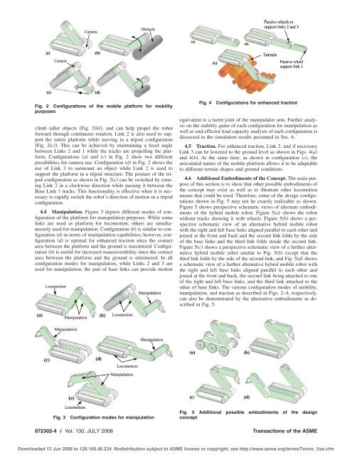
Fig. 2 Configurations <strong>of</strong> the mobile platform for mobility<br />
purposes<br />
climb taller objects Fig. 2b, <strong>and</strong> can help propel the robot<br />
forward through continuous rotation. Link 2 is also used to support<br />
the entire platform while moving in a tripod configuration<br />
Fig. 2c. This can be achieved by maintaining a fixed angle<br />
between Links 2 <strong>and</strong> 1 while the tracks are propelling the platform.<br />
Configurations a <strong>and</strong> c in Fig. 2 show two different<br />
possibilities for camera use. Configuration d in Fig. 2 shows the<br />
use <strong>of</strong> Link 3 to surmount an object while Link 2 is used to<br />
support the platform in a tripod structure. The posture <strong>of</strong> the tripod<br />
configuration as shown in Fig. 2c can be switched by rotating<br />
Link 2 in a clockwise direction while passing it between the<br />
Base Link 1 tracks. This functionality is effective when it is necessary<br />
to rapidly switch the robot’s direction <strong>of</strong> motion in a tripod<br />
configuration.<br />
4.4 Manipulation. Figure 3 depicts different modes <strong>of</strong> configuration<br />
<strong>of</strong> the platform for manipulation purposes. While some<br />
links are used as platform for locomotion, others are simultaneously<br />
used for manipulation. Configuration b is similar to configuration<br />
d in terms <strong>of</strong> manipulation capabilities; however, configuration<br />
d is optimal for enhanced traction since the contact<br />
area between the platform <strong>and</strong> the ground is maximized. Configuration<br />
b is useful for increased maneuverability since the contact<br />
area between the platform <strong>and</strong> the ground is minimized. In all<br />
configuration modes for manipulation, while Links 2 <strong>and</strong> 3 are<br />
used for manipulation, the pair <strong>of</strong> base links can provide motion<br />
Fig. 4<br />
Configurations for enhanced traction<br />
equivalent to a turret joint <strong>of</strong> the manipulator arm. Further analysis<br />
on the stability gains <strong>of</strong> each configuration for manipulation as<br />
well as end-effector load capacity analysis <strong>of</strong> each configuration is<br />
discussed in the simulation results presented in Sec. 6.<br />
4.5 Traction. For enhanced traction, Link 2, <strong>and</strong> if necessary<br />
Link 3 can be lowered to the ground level as shown in Figs. 4a<br />
<strong>and</strong> 4b. At the same time, as shown in configuration c, the<br />
articulated nature <strong>of</strong> the mobile platform allows it to be adaptable<br />
to different terrain shapes <strong>and</strong> ground conditions.<br />
4.6 Additional Embodiments <strong>of</strong> the Concept. The main purpose<br />
<strong>of</strong> this section is to show that other possible embodiments <strong>of</strong><br />
the concept may exist as well as to illustrate other locomotion<br />
means that could be used. Therefore, some <strong>of</strong> the design configurations<br />
shown in Fig. 5 may not be exactly realizable as shown.<br />
Figure 5 shows perspective schematic views <strong>of</strong> alternate embodiments<br />
<strong>of</strong> the hybrid mobile robot. Figure 5a shows the robot<br />
without tracks showing it with wheels. Figure 5b shows a perspective<br />
schematic view <strong>of</strong> an alternative hybrid mobile robot<br />
with the right <strong>and</strong> left base links aligned parallel to each other <strong>and</strong><br />
joined at the front <strong>and</strong> back <strong>and</strong> the second link folds by the side<br />
<strong>of</strong> the base links <strong>and</strong> the third link folds inside the second link.<br />
Figure 5c shows a perspective schematic view <strong>of</strong> a further alternative<br />
hybrid mobile robot similar to Fig. 5b except that the<br />
third link folds by the side <strong>of</strong> the second link; <strong>and</strong> Fig. 5d shows<br />
a schematic view <strong>of</strong> a further alternative hybrid mobile robot with<br />
the right <strong>and</strong> left base links aligned parallel to each other <strong>and</strong><br />
joined at the front <strong>and</strong> back, the second link being attached to one<br />
<strong>of</strong> the right <strong>and</strong> left base links, <strong>and</strong> the third link attached to the<br />
other <strong>of</strong> base links. The various configuration modes <strong>of</strong> mobility,<br />
manipulation, <strong>and</strong> traction as described in Figs. 2–4, respectively,<br />
can also be demonstrated by the alternative embodiments as described<br />
in Fig. 5.<br />
Fig. 3<br />
Configuration modes for manipulation<br />
Fig. 5 Additional possible embodiments <strong>of</strong> the design<br />
concept<br />
072302-4 / Vol. 130, JULY 2008 Transactions <strong>of</strong> the ASME<br />
Downloaded 13 Jun 2008 to 128.100.48.224. Redistribution subject to ASME license or copyright; see http://www.asme.org/terms/Terms_Use.cfm