Design and Analysis of a Hybrid Mobile Robot Mechanism ... - SEAS
Design and Analysis of a Hybrid Mobile Robot Mechanism ... - SEAS
Design and Analysis of a Hybrid Mobile Robot Mechanism ... - SEAS

You also want an ePaper? Increase the reach of your titles
YUMPU automatically turns print PDFs into web optimized ePapers that Google loves.
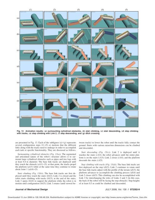
Fig. 13 Animation results: „a… surmounting cylindrical obstacles, „b… stair climbing, „c… stair descending, „d… step climbing<br />
with tracks, „e… step climbing with Link 2, „f… step descending, <strong>and</strong> „g… ditch crossing<br />
are presented in Fig. 13. Each <strong>of</strong> the subfigures a–g represents<br />
several configuration steps 1–5 or motions that the different<br />
links along with the tracks need to undergo in order to accomplish<br />
each task or specific functionality. They are discussed as follows.<br />
Surmounting cylindrical obstacles (Fig. 13(a)). The segmented<br />
<strong>and</strong> articulated nature <strong>of</strong> the robot’s structure allows it to surmount<br />
large cylindrical obstacles such as pipes <strong>and</strong> tree logs with<br />
at least 0.4 m diameter. The base link tracks are deployed until<br />
they touch the obstacle a1–3; at that point, the tracks propel<br />
the platform a3 while at the same time they continue to rotate<br />
about Joint 1 a4–5.<br />
Stair climbing (Fig. 13(b)). The base link tracks are first deployed<br />
until they touch the stairs b2; Link 2 is closed <strong>and</strong> the<br />
robot starts climbing with tracks b3; at the end <strong>of</strong> the stairs,<br />
Link 3 opens b4 to support the platform while the robot is in<br />
motion until configuration b5; Link 3 rotates until stowed between<br />
tracks to lower the robot until the tracks fully contact the<br />
ground. Stairs with various raiser/run dimensions can be climbed<br />
<strong>and</strong> descended.<br />
Stair descending (Fig. 13(c)). Link 2 is deployed until it<br />
touches the stairs c2; the robot advances until the entire platform<br />
is on the stairs c3; Link 2 closes c4; <strong>and</strong> the platform<br />
descends the stairs c5.<br />
Step climbing with tracks (Fig. 13(d)). The base link tracks are<br />
first deployed on the step d2; Link 2 continues to rotate until<br />
the base link tracks adjust with the pr<strong>of</strong>ile <strong>of</strong> the terrain d3; the<br />
platform advances to accomplish the climbing process d4 <strong>and</strong><br />
Link 2 closes d5. This climbing can also be accomplished with<br />
Link 3 by interchanging the roles <strong>of</strong> Links 2 <strong>and</strong> 3 in this case,<br />
the back <strong>of</strong> the robot will be facing the step obstacle. Step heights<br />
<strong>of</strong> at least 0.5 m could be climbed <strong>and</strong> descended.<br />
Journal <strong>of</strong> Mechanical <strong>Design</strong> JULY 2008, Vol. 130 / 072302-9<br />
Downloaded 13 Jun 2008 to 128.100.48.224. Redistribution subject to ASME license or copyright; see http://www.asme.org/terms/Terms_Use.cfm