Design and Analysis of a Hybrid Mobile Robot Mechanism ... - SEAS
Design and Analysis of a Hybrid Mobile Robot Mechanism ... - SEAS
Design and Analysis of a Hybrid Mobile Robot Mechanism ... - SEAS

Create successful ePaper yourself
Turn your PDF publications into a flip-book with our unique Google optimized e-Paper software.
Table 1<br />
<strong>Robot</strong> design specifications<br />
Total estimated weight<br />
including batteries <strong>and</strong> electronics<br />
Length arm stowed<br />
Length arm deployed<br />
Width with pliable side covers<br />
Height arm stowed<br />
65 kg<br />
814 mm<br />
2034 mm<br />
626 mm<br />
179 mm<br />
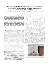
Fig. 9 Isometric view <strong>of</strong> base link track showing internal pulley<br />
arrangement<br />
Other accessories typically found in mobile robots such as cameras,<br />
lights, <strong>and</strong> antennas are embedded in the platform. In other<br />
designs <strong>of</strong> mobile robots, these items typically stick out or protrude<br />
from the platform. In order to prevent their exposure to the<br />
surrounding <strong>and</strong> thereby eliminate risk <strong>of</strong> damage in cases were<br />
the robot flips over or falls, the charge-coupled device CCD<br />
cameras <strong>and</strong> light-emitting diode LED lights were embedded in<br />
the front <strong>and</strong> back <strong>of</strong> the left <strong>and</strong> right base link tracks, respectively,<br />
as shown in Fig. 7 <strong>and</strong> the top view in Fig. 8. Two special<br />
flat antennas are embedded in the right <strong>and</strong> left side covers for<br />
Data RF signals <strong>and</strong> Audio/Video RF signals, respectively Fig.<br />
7. The flat shape <strong>of</strong> the antennas <strong>and</strong> their location in the side<br />
covers maintain the symmetric nature <strong>of</strong> the entire hybrid platform<br />
<strong>and</strong> minimize the chance for loss <strong>of</strong> data or breakage <strong>of</strong> the<br />
antenna if it were to protrude vertically up.<br />
5.3 Built-In Dual-Operation Track Tension <strong>and</strong> Suspension<br />
<strong>Mechanism</strong>. The arrangement <strong>of</strong> the supporting planetary<br />
pulleys is shown in Fig. 9. Each <strong>of</strong> the supporting pulleys is<br />
mounted on a supporting bar Fig. 9 that is connected at each end<br />
to a compression spring Fig. 6, Detail B. The ends <strong>of</strong> each supporting<br />
bar are guided through a groove on either side <strong>of</strong> the base<br />
link as shown in Detail B <strong>of</strong> Fig. 6. Therefore, each set <strong>of</strong> three<br />
planetary pulleys in the top <strong>and</strong> bottom <strong>of</strong> the left <strong>and</strong> right base<br />
link tracks is suspended by a 23 spring array. The purpose <strong>of</strong><br />
the supporting pulleys is dual <strong>and</strong> provides two very important<br />
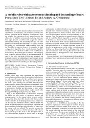
functions. While the bottom three supporting pulleys in each base<br />
link are in contact with the ground, they act as a suspension system.<br />
At the same time, the upper three supporting pulleys will<br />
provide a predetermined tension in the tracking system, as shown<br />
in Fig. 10. This dual operation track suspension <strong>and</strong> tension<br />
mechanism accounts for the symmetric nature <strong>of</strong> the design <strong>and</strong><br />
operation <strong>of</strong> the mobile robot. In other words, if the platform is<br />
inverted, the three supporting pulleys that were used as suspension<br />
will act to maintain the tension in the tracks, while the other three<br />
pulleys that were used to provide tension in the tracks will act as<br />
a suspension system. The required tension in the track belt <strong>and</strong> the<br />
suspension stroke can be preset by fastening or loosening the<br />
compression nuts Fig. 6, Detail B. Another usage <strong>of</strong> the spring<br />
array is to absorb some energy resulting from falling or flipping,<br />
thus providing compliance to impact forces. Further discussion<br />
<strong>and</strong> analysis <strong>of</strong> this mechanism are provided in Sec. 6.2.<br />
General design specifications <strong>of</strong> the robot are provided in Table<br />
1. Photos <strong>of</strong> the hybrid mobile robot physical prototype in the<br />
close <strong>and</strong> open configurations are shown in Figs. 11a <strong>and</strong> 11b.<br />
In order to support the reported mobility <strong>of</strong> this robot, a photo<br />
showing the prototype in the configuration illustrated in Fig.<br />
13a2 is shown in Fig. 11c.<br />
5.4 <strong>Robot</strong> Degrees <strong>of</strong> Freedom Coordination. The remote<br />
operating control unit OCU includes two control sticks in order<br />
to coordinate the robot degrees <strong>of</strong> freedom when generating the<br />
motions required for a given task. Of the four motors located in<br />
the base links, two are situated at the back <strong>of</strong> each <strong>of</strong> the base<br />
links <strong>and</strong> the other two at the front Fig. 8. The motor at the back<br />
<strong>of</strong> each base link provides propulsion to the track attached to that<br />
specific base link. Both motors at the back together provide the<br />
mobile robot translation <strong>and</strong> orientation in the plane <strong>of</strong> the platform.<br />
The motor at the front <strong>of</strong> the right base link propels Link 2<br />
<strong>and</strong> the motor at the front <strong>of</strong> the left base link propels Link 3<br />
Figs. 6 <strong>and</strong> 8. For the existing design, the gripper mechanism<br />
has two DOFs <strong>and</strong> hence two additional motors are located in the<br />
system.<br />
The forward, backward, right turn, <strong>and</strong> left turn motions <strong>of</strong> the<br />
base link tracks are controlled by up, down, right, <strong>and</strong> left movements<br />
<strong>of</strong> the first control stick. The second control stick is used to<br />
control Links 2 <strong>and</strong> 3 degrees <strong>of</strong> freedom. A right movement <strong>of</strong><br />
this control stick will generate a clockwise CW independent<br />
motion <strong>of</strong> Link 2 while a left movement <strong>of</strong> the stick will generate<br />
a counterclockwise CCW independent motion <strong>of</strong> Link 2. Simi-<br />
Fig. 10 Side view <strong>of</strong> base link track showing general pulley<br />
arrangement <strong>and</strong> track tension/suspension mechanism<br />
Fig. 11 A photo <strong>of</strong> the physical prototype: „a… stowed-link configuration<br />
mode, „b… open configuration mode, <strong>and</strong> „c… <strong>and</strong> „d…<br />
cylinder climbing configuration<br />
Journal <strong>of</strong> Mechanical <strong>Design</strong> JULY 2008, Vol. 130 / 072302-7<br />
Downloaded 13 Jun 2008 to 128.100.48.224. Redistribution subject to ASME license or copyright; see http://www.asme.org/terms/Terms_Use.cfm