Design and Analysis of a Hybrid Mobile Robot Mechanism ... - SEAS
Design and Analysis of a Hybrid Mobile Robot Mechanism ... - SEAS
Design and Analysis of a Hybrid Mobile Robot Mechanism ... - SEAS

You also want an ePaper? Increase the reach of your titles
YUMPU automatically turns print PDFs into web optimized ePapers that Google loves.
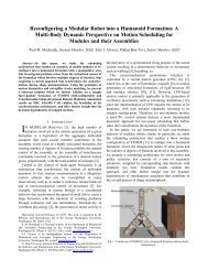
Fig. 1<br />
„a… closed configuration, „b… open configuration, <strong>and</strong> „c… exploded view<br />
platform is limited by the payload capacity <strong>of</strong> the mobile<br />
platform.<br />
Approach to solution. The manipulator arm <strong>and</strong> the mobile<br />
platform are designed <strong>and</strong> packaged as one entity<br />
rather than two separate modules. The mobile platform is<br />
part <strong>of</strong> the manipulator arm, <strong>and</strong> the arm is part <strong>of</strong> the<br />
platform. Yet, the modules are attachable <strong>and</strong> detachable.<br />
The robot links’ interchangeability to provide the functions<br />
<strong>of</strong> the mobile platform <strong>and</strong> manipulator arm requires fewer<br />
components approximately 50% reduction in the number<br />
<strong>of</strong> motors while at the same time the actuator strength<br />
capacity for manipulation purposes increases due to the hybrid<br />
nature <strong>of</strong> the mechanical structure. This approach may<br />
result in a simpler <strong>and</strong> more robust design, significant<br />
weight reduction, higher end-effector payload capability,<br />
<strong>and</strong> lower production cost.<br />
2 Issue. In designs where the mobile robot includes a manipulator<br />
arm, it is mounted <strong>and</strong> folded on top. Therefore,<br />
the arm is exposed to the surroundings <strong>and</strong> hence is susceptible<br />
to breakage <strong>and</strong> damage especially when the mobile<br />
robot is flipped over.<br />
Approach to solution. The arm <strong>and</strong> platform are designed<br />
as one entity, <strong>and</strong> the arm is part <strong>of</strong> the platform. The design<br />
architecture with the arm integrated in the platform<br />
eliminates the exposure to the surroundings when the arm<br />
is folded during motion <strong>of</strong> the mobile platform toward a<br />
target. As soon as the target is reached, the arm is deployed<br />
in order to execute desired tasks.<br />
3 Issue. When operating over rough terrain, robots <strong>of</strong>ten<br />
reach positions from where they could not be righted or<br />
controlled further for a purpose. This requires special purpose<br />
or active means for self-righting in order to restart the<br />
robot’s operation.<br />
Approach to solution. In the new design architecture, the<br />
platform is fully symmetric even with the manipulator arm<br />
integrated, thus it can continue to the target from any situation<br />
with no need <strong>of</strong> additional active means for selfrighting<br />
when it falls or flips over.<br />
4 Description <strong>of</strong> the <strong>Design</strong> Concept<br />
A new design paradigm was introduced in order to address the<br />
design problems mentioned above. The proposed approach is systematic<br />
<strong>and</strong> practical, <strong>and</strong> it addresses the overall system’s operational<br />
performance. The proposed idea is tw<strong>of</strong>old, <strong>and</strong> is described<br />
as follows.<br />
1 The mobile platform <strong>and</strong> the manipulator arm are one entity<br />
rather than two separate <strong>and</strong> attached modules. Moreover,<br />
the mobile platform can be used as part <strong>of</strong> the manipulator<br />
arm <strong>and</strong> vice versa. Thus, some <strong>of</strong> the same joints<br />
motors that provide the manipulator’s DOFs also provide<br />
the platform’s DOFs, <strong>and</strong> vice versa.<br />
2 The robot’s adaptability is enhanced by “allowing” it to flip<br />
over <strong>and</strong> continue to operate instead <strong>of</strong> trying to prevent the<br />
robot from flipping over or attempting to return it selfrighteousness.<br />
When a flipover occurs, due to a fully symmetric<br />
design with the arm integrated, it is only required to<br />
comm<strong>and</strong> the robot to continue to its destination from the<br />
current position. Furthermore, the undesirable effects <strong>of</strong><br />
flipping over or free falling are compensated by a built-in<br />
dual suspension <strong>and</strong> tension mechanism that also allows<br />
effective terrain adaptability.<br />
4.1 Concept Embodiment. To demonstrate the concept, Fig.<br />
1 depicts a possible embodiment <strong>of</strong> the proposed idea. If the platform<br />
is inverted due to flipover, the symmetric nature <strong>of</strong> the design<br />
geometrical shape Fig. 1a allows the platform to continue to<br />
the destination from its new position with no need <strong>of</strong> self-righting.<br />
Also, it is able to deploy/stow the manipulator arm from either<br />
side <strong>of</strong> the platform.<br />
The platform includes two identical base links Link 1 with<br />
tracks left <strong>and</strong> right, Link 2, Link 3, end effector, <strong>and</strong> passive<br />
wheels. To support the symmetric nature <strong>of</strong> the design, all the<br />
links are nested into one another. Link 2 is connected between the<br />
two base link tracks via Joint 1 Fig. 1b. Passive wheels are<br />
inserted between Links 2 <strong>and</strong> 3 <strong>and</strong> connected via Joint 2 <strong>and</strong><br />
another passive wheel is inserted between Link 3 <strong>and</strong> the end<br />
effector via Joint 3 Fig. 1c. The passive wheels are used to<br />
support Links 2 <strong>and</strong> 3 when used for locomotion/traction. The<br />
passive wheels may be actively used for added mobility. Link 2,<br />
Link 3, <strong>and</strong> the end effector are nested into each other to allow<br />
complete symmetry <strong>of</strong> the platform’s geometrical shape. They are<br />
connected through revolute joints <strong>and</strong> are able to provide continuous<br />
360 deg rotation <strong>and</strong> can be deployed separately or together<br />
from either side <strong>of</strong> the platform. To prevent immobilization <strong>of</strong> the<br />
platform during a flipover scenario, rounded <strong>and</strong> pliable covers<br />
are attached to the sides <strong>of</strong> the platform, as shown in Fig. 1a.<br />
The robot’s structure allows it to be scalable <strong>and</strong> can be customized<br />
according to various application needs.<br />
4.2 Modes <strong>of</strong> Operation. The links can be used in three different<br />
modes.<br />
1 All links are used for locomotion to provide added level <strong>of</strong><br />
maneuverability <strong>and</strong> traction.<br />
2 All links are used for manipulation to provide added level<br />
<strong>of</strong> manipulability. The pair <strong>of</strong> base links can provide motion<br />
equivalent to a turret joint <strong>of</strong> the manipulator arm.<br />
3 Combination <strong>of</strong> Modes 1 <strong>and</strong> 2: While some links are used<br />
for locomotion, the rest could be used for manipulation at<br />
the same time, thus the hybrid nature <strong>of</strong> the design<br />
architecture.<br />
All three modes <strong>of</strong> operation are illustrated in Figs. 2–4. In the<br />
proposed design, the motors used to drive the platform for mobility<br />
are also used for the manipulator arm to perform various<br />
tasks since the platform itself is the manipulator <strong>and</strong> vice versa. In<br />
other words, the platform can be used for mobility while at the<br />
same time it can be used as a manipulator arm to perform various<br />
tasks.<br />
4.3 Maneuverability. Figure 2 shows the use <strong>of</strong> Link 2 to<br />
support the platform for enhanced mobility purposes as well as<br />
climbing purposes. Link 2 also helps to prevent the robot from<br />
being immobilized due to high centering, also enables the robot to<br />
Journal <strong>of</strong> Mechanical <strong>Design</strong> JULY 2008, Vol. 130 / 072302-3<br />
Downloaded 13 Jun 2008 to 128.100.48.224. Redistribution subject to ASME license or copyright; see http://www.asme.org/terms/Terms_Use.cfm