Design and Analysis of a Hybrid Mobile Robot Mechanism ... - SEAS
Design and Analysis of a Hybrid Mobile Robot Mechanism ... - SEAS
Design and Analysis of a Hybrid Mobile Robot Mechanism ... - SEAS

You also want an ePaper? Increase the reach of your titles
YUMPU automatically turns print PDFs into web optimized ePapers that Google loves.
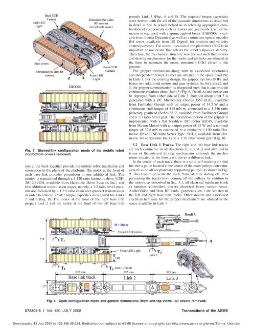
Fig. 7 Stowed-link configuration mode <strong>of</strong> the mobile robot<br />
„top/bottom covers removed…<br />
tors at the back together provide the mobile robot translation <strong>and</strong><br />
orientation in the plane <strong>of</strong> the platform. The motor at the front <strong>of</strong><br />
each base link provides propulsion to one additional link. The<br />
motion is transmitted through a 1:120 ratio harmonic drive CSF-<br />
20-120-2UH, available from Harmonic Drive Systems Inc. <strong>and</strong><br />
two additional transmission stages, namely, a 1:2 ratio bevel transmission<br />
followed by a 1:2.5 ratio chain <strong>and</strong> sprocket transmission<br />
in order to achieve greater torque capacities as required for Links<br />
2 <strong>and</strong> 3 Fig. 8. The motor at the front <strong>of</strong> the right base link<br />
propels Link 2 <strong>and</strong> the motor at the front <strong>of</strong> the left base link<br />
propels Link 3 Figs. 6 <strong>and</strong> 8. The required torque capacities<br />
were derived with the aid <strong>of</strong> the dynamic simulations as described<br />
in detail in Sec. 6, which helped us in selecting appropriate combination<br />
<strong>of</strong> components such as motors <strong>and</strong> gearheads. Each <strong>of</strong> the<br />
motors is equipped with a spring applied break FSBR007, available<br />
from Inertia Dynamics as well as a miniature optical encoder<br />
E4 series, available from US Digital for position <strong>and</strong> velocity<br />
control purposes. The overall location <strong>of</strong> the platform’s COG is an<br />
important characteristic that affects the robot’s tip-over stability.<br />
Therefore, the mechanical structure was derived such that motors<br />
<strong>and</strong> driving mechanisms for the tracks <strong>and</strong> all links are situated at<br />
the base to maintain the entire structure’s COG closer to the<br />
ground.<br />
The gripper mechanism along with its associated electronics<br />
<strong>and</strong> independent power sources are situated in the space available<br />
in Link 3. For the existing design, the gripper has two DOFs <strong>and</strong><br />
hence two additional motors <strong>and</strong> gear systems. As for Links 2 <strong>and</strong><br />
3, the gripper submechanism is integrated such that it can provide<br />
continuous rotations about Joint 3 Fig. 6, Detail A <strong>and</strong> hence can<br />
be deployed from either side <strong>of</strong> Link 3. Rotation about Joint 3 is<br />
generated with a DC Micromotor Series 3557-012C, available<br />
from Faulhaber Group with an output power <strong>of</strong> 14.5 W <strong>and</strong> a<br />
continuous stall torque <strong>of</strong> 115 mN m, connected to a 1:246 ratio<br />
planetary gearhead Series 38/2, available from Faulhaber Group<br />
<strong>and</strong> a 1:3 ratio bevel gear. The open/close motion <strong>of</strong> the gripper is<br />
implemented with a flat brushless DC motor EC45, available<br />
from Maxon Motor with an output power <strong>of</strong> 12 W <strong>and</strong> a nominal<br />
torque <strong>of</strong> 22.8 mN m connected to a miniature 1:100 ratio Harmonic<br />
Drive CSF-Mini Series Type 2XH-J, available from Harmonic<br />
Drive Systems Inc. <strong>and</strong> a 1:30 ratio worm gear Fig. 8.<br />
5.2 Base Link 1 Tracks. The right <strong>and</strong> left base link tracks<br />
are each symmetric in all directions x, y, <strong>and</strong> z <strong>and</strong> identical in<br />
terms <strong>of</strong> the internal driving mechanisms although the mechanisms<br />
situated at the front each drives a different link.<br />
In the center <strong>of</strong> each track, there is a solid self-tracking rib that<br />
fits into a guide located at the center <strong>of</strong> the main pulleys outer rim,<br />
as well as on all six planetary supporting pulleys, as shown in Fig.<br />
9. This feature prevents the track from laterally sliding <strong>of</strong>f, thus<br />
preventing the tracks from coming <strong>of</strong>f the pulleys. In addition to<br />
the motors, as described in Sec. 5.1, all electrical hardware such<br />
as batteries, controllers, drivers, electrical boxes, sensor boxes,<br />
Audio/Video <strong>and</strong> Data RF cards, gearheads, etc. are situated in<br />
the left <strong>and</strong> right base link tracks. Other motors <strong>and</strong> associated<br />
electrical hardware for the gripper mechanism are situated in the<br />
space available in Link 3.<br />
Fig. 8<br />
Open configuration mode <strong>and</strong> general dimensions „front <strong>and</strong> top views—all covers removed…<br />
072302-6 / Vol. 130, JULY 2008 Transactions <strong>of</strong> the ASME<br />
Downloaded 13 Jun 2008 to 128.100.48.224. Redistribution subject to ASME license or copyright; see http://www.asme.org/terms/Terms_Use.cfm