AdvancedTCA Shelf, 5-slot - ATCA - Schroff's AdvancedTCA ...
AdvancedTCA Shelf, 5-slot - ATCA - Schroff's AdvancedTCA ...
AdvancedTCA Shelf, 5-slot - ATCA - Schroff's AdvancedTCA ...

You also want an ePaper? Increase the reach of your titles
YUMPU automatically turns print PDFs into web optimized ePapers that Google loves.
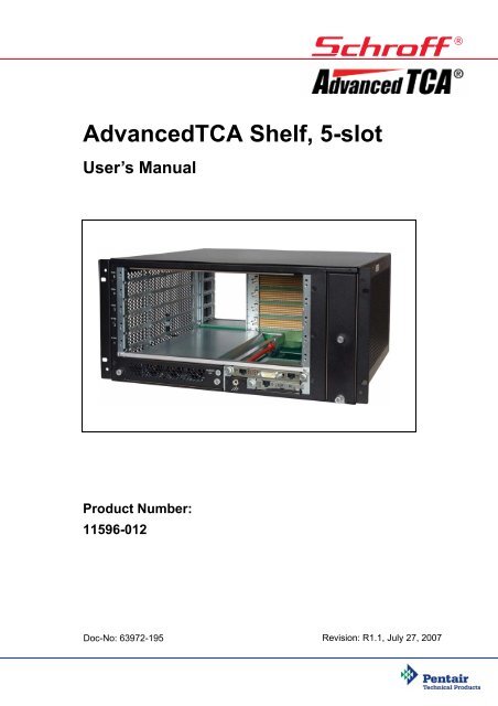
<strong>AdvancedTCA</strong> <strong>Shelf</strong>, 5-<strong>slot</strong><br />
User’s Manual<br />
Product Number:<br />
11596-012<br />
Doc-No: 63972-195<br />
Revision: R1.1, July 27, 2007
Rev. Date updated Change<br />
D1.0 January 30, 2007 Draft Release<br />
R1.0 June 20, 2007 Initial Release<br />
R1.1 July 27, 2007 Minor layout improvements<br />
Impressum:<br />
Schroff GmbH<br />
D-75334 Straubenhardt, Germany<br />
The details in this manual have been carefully compiled and<br />
checked - supported by certified Quality Management System<br />
to EN ISO 9001/2000<br />
The company cannot accept any liability for errors or misprints.<br />
The company reserves the right to amendments of technical<br />
specifications due to further development and improvement of<br />
products.<br />
Copyright © 2007<br />
All rights and technical modifications reserved.
Schroff 5-Slot <strong>AdvancedTCA</strong> <strong>Shelf</strong><br />
11596-012<br />
Table of Contents<br />
1 Safety................................................................................................................. 1<br />
1.1 Safety Symbols used in this document................................................................ 1<br />
1.2 General Safety Precautions................................................................................. 1<br />
1.3 References and Architecture Specifications ........................................................ 2<br />
1.4 Product Definition ................................................................................................ 2<br />
1.5 Terms and Acronyms........................................................................................... 3<br />
2 Hardware Platform............................................................................................ 4<br />
2.1 <strong>Shelf</strong> Front View .................................................................................................. 5<br />
2.2 ESD Wrist Strap Terminals.................................................................................. 5<br />
3 <strong>ATCA</strong> Backplane............................................................................................... 6<br />
3.1 Logical to Physical Slot Mapping ......................................................................... 6<br />
3.2 Interfaces ............................................................................................................. 6<br />
3.2.1 Base Interface........................................................................................ 6<br />
3.2.2 Fabric Interface...................................................................................... 6<br />
3.2.3 Synchronization Clock Interface ............................................................ 6<br />
3.2.4 Update Channel Interface...................................................................... 7<br />
3.2.5 Intelligent Platform Management Interface ............................................ 7<br />
3.3 Non-<strong>ATCA</strong> Connectors on the <strong>ATCA</strong> Backplane................................................. 8<br />
3.3.1 SAP Backplane Connector .................................................................... 8<br />
3.3.2 <strong>Shelf</strong> Manager Backplane connector..................................................... 8<br />
3.3.3 IPMB-A and IPMB-B Connectors (Custom Configuration)..................... 8<br />
3.4 <strong>Shelf</strong> SEEPROM.................................................................................................. 9<br />
4 Air Filter........................................................................................................... 10<br />
4.1 Introduction ........................................................................................................ 10<br />
4.2 Air Filter Replacement ....................................................................................... 10<br />
5 <strong>Shelf</strong> Ground Connection .............................................................................. 11<br />
5.1 Specification for the <strong>Shelf</strong> Ground connection cable ......................................... 11<br />
6 <strong>Shelf</strong> Alarm Panel (Accessory sold separately) .......................................... 12<br />
6.1 SAP Front Panel ................................................................................................ 12<br />
6.2 SAP Block Diagram ........................................................................................... 13<br />
6.3 SAP SEEPROM................................................................................................. 13<br />
6.4 SAP I²C Addresses............................................................................................ 13<br />
6.5 User definable LEDs.......................................................................................... 14<br />
6.6 RS-232 Serial Console Interfaces on SAP ........................................................ 14<br />
6.7 SAP Console Cable for the <strong>Shelf</strong> Manger Serial Interface ................................ 15<br />
6.7.1 <strong>Shelf</strong> Alarm Panel Backplane Connector............................................. 16<br />
6.8 SAP Temperature Sensor.................................................................................. 16<br />
www.a-tca.com / www.schroff.biz I R1.1, July 27, 2007
Schroff 5-Slot <strong>AdvancedTCA</strong> <strong>Shelf</strong><br />
11596-012<br />
6.9 SAP PCA9555 ................................................................................................... 17<br />
6.10 SAP Telco Alarms.............................................................................................. 18<br />
6.10.1 Telco Alarm Interface........................................................................... 18<br />
6.10.2 Telco Alarm LEDs................................................................................ 18<br />
6.10.3 Alarm Silence Push Button .................................................................. 18<br />
6.10.4 Alarm Reset ......................................................................................... 18<br />
6.10.5 Telco Alarm Connector (DB15-male)................................................... 19<br />
7 Fan Tray........................................................................................................... 20<br />
7.1 Introduction ........................................................................................................ 20<br />
7.2 Fan Control Module ........................................................................................... 21<br />
7.3 Fan Control Module Block Diagram................................................................... 21<br />
7.4 Fan Control Module Features ............................................................................ 22<br />
7.5 Power Supply..................................................................................................... 23<br />
7.6 AC Power Supply............................................................................................... 24<br />
7.6.1 Power Supply Backplane Connector ................................................... 24<br />
8 <strong>Shelf</strong> Manager ................................................................................................. 25<br />
8.1 Introduction ........................................................................................................ 25<br />
8.2 Front Panel Components................................................................................... 27<br />
8.3 Bused IPMB Interface........................................................................................ 28<br />
8.4 Ethernet Channels ............................................................................................. 28<br />
8.5 Master-Only I²C Bus .......................................................................................... 29<br />
8.6 <strong>Shelf</strong> Manager RS-232 Serial Interface ............................................................. 30<br />
8.7 Front Panel RESET push button ....................................................................... 30<br />
8.8 Input Voltage and Fuse Monitoring.................................................................... 31<br />
8.9 Hardware Address ............................................................................................. 31<br />
8.10 Hot Swap Interface ............................................................................................ 32<br />
8.11 Hot Swap Switch and Board Presence.............................................................. 32<br />
8.11.1 Hot Swap Switch.................................................................................. 32<br />
8.11.2 Board Presence ................................................................................... 32<br />
8.11.3 Hot Swap LED ..................................................................................... 32<br />
8.12 RTC Backup Battery (Assembly option) ............................................................ 33<br />
8.13 Reprogramming of the FLASH Memory in the ShMM-500 ................................ 34<br />
8.13.1 Introduction .......................................................................................... 34<br />
8.13.2 Reprogramming the <strong>Shelf</strong> Manager from a TFTP server..................... 34<br />
8.14 <strong>Shelf</strong> Manager Front Panel and Backplane connectors .................................... 35<br />
9 Technical Data ................................................................................................ 37<br />
9.1 <strong>Shelf</strong> Mechanical Dimensions............................................................................ 38<br />
www.a-tca.com / www.schroff.biz II R1.1, July 27, 2007
Schroff 5-Slot <strong>AdvancedTCA</strong> <strong>Shelf</strong><br />
11596-012<br />
Safety<br />
1 Safety<br />
The intended audience of this User’s Manual is system integrators and<br />
hardware/software engineers.<br />
1.1 Safety Symbols used in this document<br />
Hazardous voltage!<br />
This is the electrical hazard symbol. It indicates that there are dangerous<br />
voltages inside the <strong>Shelf</strong>.<br />
Caution!<br />
This is the user caution symbol. It indicates a condition where damage of the<br />
equipment or injury of the service personnel could occur. To reduce the risk of<br />
damage or injury, follow all steps or procedures as instructed.<br />
Danger of electrostatic discharge!<br />
The <strong>Shelf</strong> contains static sensitive devices. To prevent static damage you must<br />
wear an ESD wrist strap.<br />
1.2 General Safety Precautions<br />
Warning!<br />
Voltages over 60 VDC can be present in this equipment. As defined in the<br />
PICMG 3.0 Specification, this equipment is intended to be accessed, to be<br />
installed and maintained by qualified and trained service personnel only.<br />
• Service personnel must know the necessary electrical safety, wiring and<br />
connection practices for installing this equipment in a telecommunication<br />
environment.<br />
• Install this equipment only in compliance with local and national electrical<br />
codes.<br />
• For additional information about this equipment, see the PICMG 3.0<br />
Specification (www.picmg.com).<br />
www.a-tca.com / www.schroff.biz 1 R1.1, July 27, 2007
Schroff 5-Slot <strong>AdvancedTCA</strong> <strong>Shelf</strong><br />
11596-012<br />
Safety<br />
1.3 References and Architecture Specifications<br />
• Pigeon Point Systems IPM Sentry <strong>Shelf</strong>-External Interface Reference<br />
(www.pigeonpoint.com)<br />
• PICMG ® 3.0 Revision 2.0 <strong>AdvancedTCA</strong>® Base Specification<br />
(www.picmg.com)<br />
• PICMG ® Engineering Change Notice ECN 3.0-2.0-002<br />
• Control Resources Smart Fan Multi SD - Installation & Operation Manual<br />
www.controlres.com<br />
1.4 Product Definition<br />
The Schroff 11596-012 is a 5 U / 5 Slot <strong>AdvancedTCA</strong> <strong>Shelf</strong> with AC power<br />
supply for Enterprise or Development applications.<br />
The <strong>Shelf</strong> has provisions for a Schroff ShMM-ACB-IV <strong>Shelf</strong> Manager and a <strong>Shelf</strong><br />
Alarm Panel (SAP) for Telco Alarms and RS-232 interface.<br />
Use of independent Fan Control Modules (FCMs) allows the <strong>Shelf</strong> to function<br />
without the use of <strong>Shelf</strong> Managers.<br />
<strong>ATCA</strong> Blades are intended to operate with <strong>Shelf</strong> Managers, many <strong>ATCA</strong><br />
Blades can be configured to operate without <strong>Shelf</strong> Management. Please<br />
consult your <strong>ATCA</strong> Blade’s User Manual.<br />
Schroff <strong>Shelf</strong> Manager and SAP are available as accessory items.<br />
www.a-tca.com / www.schroff.biz 2 R1.1, July 27, 2007
Schroff 5-Slot <strong>AdvancedTCA</strong> <strong>Shelf</strong><br />
11596-012<br />
Safety<br />
1.5 Terms and Acronyms<br />
Table 1: Terms and Acronyms<br />
Term<br />
<strong>ATCA</strong><br />
Backplane<br />
CDM<br />
Chassis<br />
CMM<br />
ECN<br />
ESD<br />
ETSI<br />
FRU<br />
IPMB<br />
IPMC<br />
IPMI<br />
PCB<br />
PEM<br />
RTC<br />
RTM<br />
<strong>Shelf</strong><br />
VRTN<br />
Definition<br />
Advanced Telecom Computing Architecture<br />
Passive circuit board providing the connectors for the front boards. Power distribution,<br />
management and auxiliary signal connections are supported<br />
Chassis Data Module<br />
Enclosure containing subrack, Backplane, boards, cooling devices, PEMs, same as <strong>Shelf</strong><br />
Chassis Management Module, same as <strong>Shelf</strong> Manager<br />
Engineering Change Notice<br />
Electrostatic Discharge<br />
European Telecommunications Standards Institute<br />
Field Replaceable Unit<br />
Intelligent Platform Management Bus<br />
Intelligent Platform Management Controller<br />
Intelligent Platform Management Interface<br />
Printed Circuit Board<br />
Power Entry Module<br />
Real Time Clock<br />
Rear Transition Module<br />
See Chassis<br />
Voltage Return<br />
www.a-tca.com / www.schroff.biz 3 R1.1, July 27, 2007
Schroff 5-Slot <strong>AdvancedTCA</strong> <strong>Shelf</strong><br />
11596-012<br />
Hardware Platform<br />
2 Hardware Platform<br />
The Schroff 5 U / 5 Slot <strong>AdvancedTCA</strong> <strong>Shelf</strong> implements the following features:<br />
• 5 <strong>slot</strong> <strong>ATCA</strong> Backplane with triple replicated Mesh Fabric Interface, Dual<br />
Star Base Interface and bused IPMB interface, supporting three 8 U node<br />
board <strong>slot</strong>s and two 8 U hub <strong>slot</strong>s<br />
• Mounting brackets for 19“ cabinets<br />
• Removable top cover allows easy access to top blade for debugging during<br />
development<br />
• ESD Wrist Strap Terminals at front and rear<br />
• Dedicated <strong>slot</strong> for a Schroff <strong>Shelf</strong> Manager based on Pigeon Point ShMM-<br />
500<br />
• Cooling for 200 W per Front Board and 15 W for each RTM<br />
• Front pluggable Fan Tray and removable NEBS compliant Air Filter<br />
• Pluggable 1200 W AC power supply with 20 A circuit breaker protection<br />
• Power LED indicator shows presence of input power<br />
• Dedicated <strong>slot</strong> for a Schroff <strong>Shelf</strong> Alarm Panel (SAP) that provides Telco<br />
Alarm interface, Alarm Status LEDs and serial interface for the <strong>Shelf</strong><br />
Manager<br />
www.a-tca.com / www.schroff.biz 4 R1.1, July 27, 2007
Schroff 5-Slot <strong>AdvancedTCA</strong> <strong>Shelf</strong><br />
11596-012<br />
Hardware Platform<br />
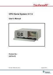
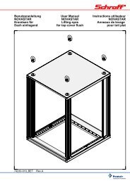
2.1 <strong>Shelf</strong> Front View<br />
Figure 1: <strong>Shelf</strong> Front and Rear View<br />
12707826<br />
1 Front Card Cage 8 Power Entry Module<br />
2 Temperature Sensor 9 Air Filter and Fan Tray<br />
3 AC Power Supply 10 <strong>ATCA</strong> 5-Slot Backplane<br />
4 Power LED 11 <strong>Shelf</strong> Alarm Panel (SAP)<br />
5 Front ESD Wrist Strap Terminal 12 <strong>Shelf</strong> Manager<br />
6 Rear Card Cage 13 Rear ESD Wrist Strap Terminal<br />
7 <strong>Shelf</strong> Ground Terminal<br />
2.2 ESD Wrist Strap Terminals<br />
Danger of electrostatic discharge!<br />
Static electricity can harm delicate components inside the <strong>Shelf</strong>. You must<br />
wear an ESD wrist strap before exchanging any part or electric component!<br />
The ESD Wrist Strap Terminals (4 mm banana jacks) are located at the lower<br />
front and rear side of the <strong>Shelf</strong>.<br />
www.a-tca.com / www.schroff.biz 5 R1.1, July 27, 2007
Schroff 5-Slot <strong>AdvancedTCA</strong> <strong>Shelf</strong><br />
11596-012<br />
<strong>ATCA</strong> Backplane<br />
3 <strong>ATCA</strong> Backplane<br />
The 5-<strong>slot</strong> <strong>ATCA</strong> monolithic Backplane provides:<br />
• 3 <strong>ATCA</strong> Node <strong>slot</strong>s<br />
• 2 <strong>ATCA</strong> Hub <strong>slot</strong>s<br />
• 1 <strong>slot</strong> for optional <strong>Shelf</strong> Manager<br />
• 1 <strong>slot</strong> for optional SAP<br />
• 1 <strong>slot</strong> for AC Power Supply<br />
3.1 Logical to Physical Slot Mapping<br />
The physical and logical <strong>slot</strong>s are sequentially numbered from the lower to the<br />
upper side.<br />
Table 2: 5-Slot <strong>ATCA</strong> Backplane physical to logical <strong>slot</strong> mapping<br />
Physical<br />
Slot #<br />
Logical Slot<br />
#<br />
HW-Address<br />
(Hex)<br />
IPMB-<br />
Address<br />
(Hex)<br />
Update<br />
Channel<br />
Power<br />
Domain<br />
Node 5 5 45 8A 1<br />
Node 4 4 44 88 2<br />
Node 3 3 43 86 1<br />
Hub Slot 2 2 42 84 2<br />
Hub Slot 1 1 41 82 1<br />
3.2 Interfaces<br />
3.2.1 Base Interface<br />
3.2.2 Fabric Interface<br />
Logical <strong>slot</strong>s 1 and 2 are the hub <strong>slot</strong>s for the Dual Star Base Interface.<br />
The Fabric Interface in the <strong>ATCA</strong> Backplane is routed as triple replicated Full<br />
Mesh with 3 Channels (24 differential pairs total), interconnecting each <strong>ATCA</strong><br />
<strong>slot</strong>. See PICMG® 3.0 <strong>AdvancedTCA</strong>® Base Specification for details.<br />
3.2.3 Synchronization Clock Interface<br />
Six pairs of synchronization clocks are bused between all 5 <strong>ATCA</strong> <strong>slot</strong>s and<br />
terminated at each end with an 80.5 Ohm resistor across the differential signal<br />
line for each of the six differential pairs.<br />
www.a-tca.com / www.schroff.biz 6 R1.1, July 27, 2007
Schroff 5-Slot <strong>AdvancedTCA</strong> <strong>Shelf</strong><br />
11596-012<br />
<strong>ATCA</strong> Backplane<br />
3.2.4 Update Channel Interface<br />
The Update Channels are each routed with 10 differential pairs between <strong>slot</strong> 1<br />
and 2 and between <strong>slot</strong> 3 and 4. (See Table 2 in this Chapter)<br />
The Update Channel can be used to pass data or routing information between<br />
two redundant <strong>ATCA</strong> Boards.<br />
3.2.5 Intelligent Platform Management Interface<br />
The <strong>Shelf</strong> uses an Intelligent Platform Management Bus (IPMB) for<br />
management communications among all <strong>ATCA</strong> Boards and the <strong>Shelf</strong><br />
Managers. The reliability of the IPMB is improved by the addition of a second<br />
IPMB, with the two IPMBs referenced as IPMB-A and IPMB-B.<br />
The IPMB-A and IPMB-B are routed to the <strong>ATCA</strong> <strong>slot</strong>s in a bused configuration.<br />
Figure 2: Bused IPMB<br />
<strong>ATCA</strong> Board<br />
<strong>ATCA</strong> Board<br />
<strong>ATCA</strong> Board<br />
IPMC IPMC IPMC<br />
<strong>Shelf</strong> Manager<br />
IPMB-A<br />
IPMB-B<br />
12706973<br />
www.a-tca.com / www.schroff.biz 7 R1.1, July 27, 2007
Schroff 5-Slot <strong>AdvancedTCA</strong> <strong>Shelf</strong><br />
11596-012<br />
<strong>ATCA</strong> Backplane<br />
3.3 Non-<strong>ATCA</strong> Connectors on the <strong>ATCA</strong> Backplane<br />
3.3.1 SAP Backplane Connector<br />
For pin assignment see Chapter 6.7.1, "<strong>Shelf</strong> Alarm Panel Backplane<br />
Connector".<br />
3.3.2 <strong>Shelf</strong> Manager Backplane connector<br />
The <strong>Shelf</strong> Manager Backplane connector provide interface for:<br />
• IPMB-A and IPMB-B (I²C-bus)<br />
• Base Interface Channel 1 (ShMC) of the Base Interface Hub <strong>slot</strong>s<br />
For pin assignment see Table 16 and Table 17.<br />
3.3.3 IPMB-A and IPMB-B Connectors (Custom Configuration)<br />
Provisions for IPMB-A and IPMB-B connectors are located at the rear upper side<br />
of the Backplane. Installation of the connectors is available on customer<br />
request.<br />
Figure 3: IPMB-A and IPMB-B connectors<br />
Table 3: IPMB_A Connector<br />
12706944<br />
Pin#<br />
Description<br />
1 IPMB-A, Serial clock,<br />
2 Logic Ground<br />
3 IPMB-A, Serial Data<br />
4 3,3 VDC power supply for <strong>Shelf</strong> I²C-bus devices<br />
Table 4: IPMB_B Connector<br />
Pin#<br />
Description<br />
1 IPMB-B, Serial clock<br />
2 Logic Ground<br />
3 IPMB-B, Serial Data<br />
4 3,3 VDC power supply for <strong>Shelf</strong> I²C-bus devices<br />
www.a-tca.com / www.schroff.biz 8 R1.1, July 27, 2007
Schroff 5-Slot <strong>AdvancedTCA</strong> <strong>Shelf</strong><br />
11596-012<br />
<strong>ATCA</strong> Backplane<br />
3.4 <strong>Shelf</strong> SEEPROM<br />
The <strong>Shelf</strong> SEEPROM is located at the Backplane. It is a repository of the <strong>Shelf</strong><br />
specific information, capabilities of the system and other user configurable<br />
options. The two SEEPROMs are directly accessible by the <strong>Shelf</strong> Managers<br />
dedicated I²C bus.<br />
The SEEPROM contains as example:<br />
- a list of which <strong>slot</strong>s are connected together<br />
- how the update channels are routed<br />
- how many <strong>slot</strong>s are in the system<br />
- what the maximum power is to each <strong>slot</strong><br />
- the serial number of the shelf<br />
- the backplane topology etc.<br />
The <strong>Shelf</strong> Manager use this information to provide functions such as electronic<br />
keying, controlling the power state of the system, etc.<br />
The <strong>Shelf</strong> Manager cache the information that is stored in the SEEPROMs so<br />
that the SEEPROM is only needed when the <strong>Shelf</strong> Manager is first inserted or<br />
when the <strong>Shelf</strong> is first turned on.<br />
The redundant SEEPROMs ensure that if one is corrupt or non-functional, the<br />
second can provide the necessary information. The <strong>Shelf</strong> Manager selects what<br />
set of information is correct and then synchronizes the two SEEPROMs from the<br />
internally cached copy of the SEEPROM information.<br />
Table 5: <strong>Shelf</strong> SEEPROM I²C addresses<br />
SEEPROM I²C-Channel I²C-bus address<br />
1 Channel 1 0xa4 / 52<br />
2 Channel 2 0xa4 / 52<br />
www.a-tca.com / www.schroff.biz 9 R1.1, July 27, 2007
Schroff 5-Slot <strong>AdvancedTCA</strong> <strong>Shelf</strong><br />
11596-012<br />
Air Filter<br />
4 Air Filter<br />
Figure 4: Air Filter<br />
12706936<br />
1 Air Filter Front Panel 3 Filter Element<br />
2 Captive Thumbscrew 4 Fixing screws<br />
4.1 Introduction<br />
The <strong>ATCA</strong> <strong>Shelf</strong> provides a front replaceable air filter.<br />
The air filter is a 1/4“ thick 25PPI filter.<br />
4.2 Air Filter Replacement<br />
1 Loosen the captive thumbscrew (2) and pull out the Air Filter.<br />
2 Unscrew both Fixing Screws (4) and replace the Filter Element (3).<br />
www.a-tca.com / www.schroff.biz 10 R1.1, July 27, 2007
Schroff 5-Slot <strong>AdvancedTCA</strong> <strong>Shelf</strong><br />
11596-012<br />
<strong>Shelf</strong> Ground Connection<br />
5 <strong>Shelf</strong> Ground Connection<br />
Hazardous voltage!<br />
Before powering-up the <strong>Shelf</strong>, make sure that the <strong>Shelf</strong> Ground terminals are<br />
connected to Protective Earth (PE) of the building.<br />
The <strong>ATCA</strong> <strong>Shelf</strong> provides a <strong>Shelf</strong> ground terminal at the lower rear side.The<br />
<strong>Shelf</strong> ground terminal provides two studs (10-32 UNF) with a 15.88 mm spacing<br />
between stud centers to connect a double-lug <strong>Shelf</strong> ground terminal cable.<br />
Figure 5: <strong>Shelf</strong> Ground Terminal<br />
1 <strong>Shelf</strong> Ground Terminal<br />
12707827<br />
5.1 Specification for the <strong>Shelf</strong> Ground connection cable<br />
Required wire size: AWG10<br />
Required terminals: Use only double lug terminals.<br />
www.a-tca.com / www.schroff.biz 11 R1.1, July 27, 2007
Schroff 5-Slot <strong>AdvancedTCA</strong> <strong>Shelf</strong><br />
11596-012<br />
<strong>Shelf</strong> Alarm Panel (Accessory sold separately)<br />
6 <strong>Shelf</strong> Alarm Panel (Accessory sold separately)<br />
Some <strong>Shelf</strong> Manager I/O functionalities have been moved to a separate board<br />
called <strong>Shelf</strong> Alarm Panel (SAP). The <strong>Shelf</strong> Alarm Panel is located at the lower<br />
front side of the <strong>Shelf</strong>. It provides:<br />
• 3 <strong>Shelf</strong> Alarm LEDs (MINOR, MAJOR, CRITICAL)<br />
• 3 User definable LEDs<br />
• The Telco Alarm connector (DB15-male)<br />
• The Alarm Silence Push Button<br />
• Serial console interfaces for Schroff <strong>Shelf</strong> Managers (RJ45 connectors)<br />
Figure 6: Connection between <strong>Shelf</strong> Manager and SAP<br />
MIN 3<br />
U<br />
SERIAL 1 MAJ 2<br />
S<br />
E<br />
SERIAL 2<br />
CRIT 1 R<br />
RST<br />
CH0<br />
Serial Console Interface<br />
Enable<br />
Buffer<br />
LTC4300<br />
Master-Only<br />
I²C-bus<br />
ShMM-500<br />
<strong>Shelf</strong> Manager<br />
6.1 SAP Front Panel<br />
Figure 7: Front Panel SAP<br />
12706941<br />
12706932<br />
1 Fixing screw 7 LED USER 2<br />
2 Serial Interface for <strong>Shelf</strong> Manager 8 LED USER 3<br />
3 LED Minor Alarm (amber) 9 Telco Alarm Connector<br />
4 LED Major Alarm (red) 10 Alarm Silence button<br />
5 LED Critical Alarm (red) 11 Serial Interface for <strong>Shelf</strong> Manager 2<br />
(not used in this <strong>Shelf</strong>)<br />
6 LED USER 1<br />
www.a-tca.com / www.schroff.biz 12 R1.1, July 27, 2007
Schroff 5-Slot <strong>AdvancedTCA</strong> <strong>Shelf</strong><br />
11596-012<br />
<strong>Shelf</strong> Alarm Panel (Accessory sold separately)<br />
6.2 SAP Block Diagram<br />
Figure 8: SAP Block Diagram<br />
User 1<br />
SDA/SCL (I2C Bus CH0)<br />
User 2<br />
User 3<br />
LED<br />
Buffer<br />
LM75 Temp.<br />
Sensor<br />
0x96<br />
SEEPROM<br />
0xa6<br />
TELCO Alarm Connector<br />
ALARM LEDs<br />
Critical<br />
Major<br />
Minor<br />
ALARM SILENCE<br />
Critical Alarm<br />
Major Alarm<br />
Minor Alarm<br />
Power Alarm<br />
Minor Clear<br />
Major Clear<br />
PCA9555<br />
I2C-bus I/O port<br />
0x44<br />
SAP Presence<br />
I2C_PWR_A (ShMC1)<br />
3.3 V I2C_PWR_B (ShMC1)<br />
I2C_PWR_A (ShMC2)<br />
I2C_PWR_B (ShMC2)<br />
INV_ACTIVE_ACB1<br />
INV_ACTIVE_ACB2<br />
Backplane Connector<br />
RJ45<br />
ESD<br />
protection<br />
Serial Console of<br />
<strong>Shelf</strong> Manager 1<br />
RJ45<br />
ESD<br />
protection<br />
Serial Console of<br />
<strong>Shelf</strong> Manager 2<br />
12706921<br />
6.3 SAP SEEPROM<br />
The SAP SEEPROM is connected to the Master-Only I²C-bus and is a Microchip<br />
24LC256 device.<br />
6.4 SAP I²C Addresses<br />
Table 6: SAP I²C Addresses<br />
LM75 SEEPROM PCA9555<br />
0x96/0x4b 0xa6/0x53 0x44/0x22<br />
www.a-tca.com / www.schroff.biz 13 R1.1, July 27, 2007
Schroff 5-Slot <strong>AdvancedTCA</strong> <strong>Shelf</strong><br />
11596-012<br />
<strong>Shelf</strong> Alarm Panel (Accessory sold separately)<br />
6.5 User definable LEDs<br />
The LEDs USER (1, 2, 3) are user definable and connected to the I²C-bus I/O<br />
port of the PCA 9555 on the SAP.<br />
6.6 RS-232 Serial Console Interfaces on SAP<br />
Figure 9: RS-232 Serial Console Interface on <strong>Shelf</strong> Alarm Panel<br />
Pin 1 Pin 8<br />
The SAP provides two RS-232 serial console connector (SERIAL 1 and 2) for<br />
<strong>Shelf</strong> Manager 1 and 2. The connectors are 8-pin RJ45 modular receptacles.<br />
A full set of RS-232 signals, including modem control, is provided. The serial<br />
interface is implemented on the ShMM-500.<br />
In the 11596-012 <strong>Shelf</strong> only the Connector “serial 1“ is used!<br />
12705811<br />
The serial console default configuration is:<br />
• 115200 baud<br />
• no parity<br />
• 8 data bits<br />
• 1 stop bit<br />
Table 7: RS-232 Serial Console Interface Pin assignment<br />
RJ45 Pin<br />
RS-232<br />
Signal<br />
ShMM-500<br />
Signal<br />
Type<br />
Description<br />
1 RTS RTS Out Request To Send<br />
2 DTR DTR Out Data Terminal Ready<br />
3 TxD TXD0 Out Transmit Data<br />
4 GND GND --- Logic Ground<br />
5 GND GND --- Logic Ground<br />
6 RxD RXD0 In Receive Data<br />
7 DSR DSR In Data Set Ready<br />
8 CTS CTS In Clear To Send<br />
www.a-tca.com / www.schroff.biz 14 R1.1, July 27, 2007
Schroff 5-Slot <strong>AdvancedTCA</strong> <strong>Shelf</strong><br />
11596-012<br />
<strong>Shelf</strong> Alarm Panel (Accessory sold separately)<br />
6.7 SAP Console Cable for the <strong>Shelf</strong> Manger Serial Interface<br />
Figure 10: RJ45 to DB9 Serial Console Cable<br />
RJ45-male<br />
1 8<br />
RTS<br />
DTR<br />
TxD<br />
GND<br />
GND<br />
RxD<br />
DSR<br />
CTS<br />
1<br />
2<br />
3<br />
4<br />
5<br />
6<br />
7<br />
8<br />
8<br />
6<br />
2<br />
5<br />
5<br />
3<br />
4<br />
7<br />
CTS<br />
DSR<br />
RxD<br />
GND<br />
GND<br />
TxD<br />
DTR<br />
RTS<br />
DB9-female<br />
5 1<br />
9 6<br />
12706929<br />
The connectors are shown with the cables pointing away.<br />
Serial Console Cable: Accessory sold separately.<br />
Schroff Catalog-No: 23204-187<br />
www.a-tca.com / www.schroff.biz 15 R1.1, July 27, 2007
Schroff 5-Slot <strong>AdvancedTCA</strong> <strong>Shelf</strong><br />
11596-012<br />
<strong>Shelf</strong> Alarm Panel (Accessory sold separately)<br />
6.7.1 <strong>Shelf</strong> Alarm Panel Backplane Connector<br />
Figure 11: <strong>Shelf</strong> Alarm Panel Backplane Connector<br />
12706926<br />
Table 8: <strong>Shelf</strong> Alarm Panel Backplane Connector Pin Assignment<br />
6.8 SAP Temperature Sensor<br />
SAP <strong>ATCA</strong> Backplane Connector<br />
Pin A Description B Description C Description<br />
1 -48V_A -48 V Feed A -48V_B -48 V Feed B<br />
2 VRTN_A Voltage return Feed<br />
A<br />
3 VRTN_B Voltage return Feed<br />
B<br />
4<br />
5 I2C_PWR_A 3.6 V from <strong>Shelf</strong><br />
Manager<br />
6 GND Ground GND Ground<br />
I2C_PWR_B<br />
3.6 V from <strong>Shelf</strong><br />
Manager<br />
7 SDA_CH0 Data I²C-bus<br />
Channel 0<br />
GND<br />
Ground<br />
8 SCL_CH0 Clock I²C-bus<br />
Channel 0<br />
INT<br />
GND<br />
9 RXD0_ACB1 Receive Data<br />
<strong>Shelf</strong> Manager<br />
10 DSR_ACB1 Data Set Ready<br />
<strong>Shelf</strong> Manager<br />
DTR_ACB1<br />
Data Terminal Ready<br />
<strong>Shelf</strong> Manager<br />
11 CD_ACB1 Carrier Detect<br />
<strong>Shelf</strong> Manager<br />
12 CTS_ACB1 Clear To Send<br />
<strong>Shelf</strong> Manager<br />
13 TXD0_ACB1 Transmit Data<br />
<strong>Shelf</strong> Manager<br />
14<br />
RTS_ACB1<br />
Request To Send<br />
<strong>Shelf</strong> Manager<br />
15 SAP_PRES SAP Presence signal<br />
to <strong>Shelf</strong> Manager<br />
SCL_A<br />
16 INV_ACTIVE_A<br />
CB1<br />
Active signal from<br />
<strong>Shelf</strong> Manager<br />
SHELF_GND<br />
<strong>Shelf</strong> Ground<br />
The LM75 temperature sensor measuring the board temperature is located on<br />
the SAP PCB. The temperature sensor is connected to the Master-Only I²C-bus.<br />
www.a-tca.com / www.schroff.biz 16 R1.1, July 27, 2007
Schroff 5-Slot <strong>AdvancedTCA</strong> <strong>Shelf</strong><br />
11596-012<br />
<strong>Shelf</strong> Alarm Panel (Accessory sold separately)<br />
6.9 SAP PCA9555<br />
The PCA9555 device:<br />
• controls the status of the LEDs<br />
• reads the status of the Telco Alarm Cutoff push button (CLEAR)<br />
• controls the Telco Alarm relays<br />
Table 9: SAP PCA9555 Device Function<br />
D<br />
PCA9555 I/O pins Function State<br />
0.0 Power Alarm to telco relays output 1 = relays powered<br />
0.1 Minor Alarm to telco relays output 1 = relays powered<br />
0.2 Major Alarm to telco relays output 1 = relays powered<br />
0.3 Critical Alarm to telco relays output 1 = relays powered<br />
0.4 N/C Pulled High<br />
0.5 LED_MIN (Minor alarm LED) output 1 = On<br />
0.6 LED_MAJ (Major alarm LED) output 1 = On<br />
0.7 LED_CRIT (Critical alarm LED) output 1 = On<br />
1.0 Alarm cutoff push button input 0 = push button pushed<br />
1.1 Minor Clear input 0 = voltage applied to input pins<br />
1.2 Major Clear input 0 = voltage applied to input pins<br />
1.3 N/C Pulled High<br />
1.4 N/C Pulled High<br />
1.5 LED_USER3 output 1 = On<br />
1.6 LED_USER2 output 1 = On<br />
1.7 LED_USER1 output 1 = On<br />
www.a-tca.com / www.schroff.biz 17 R1.1, July 27, 2007
Schroff 5-Slot <strong>AdvancedTCA</strong> <strong>Shelf</strong><br />
11596-012<br />
<strong>Shelf</strong> Alarm Panel (Accessory sold separately)<br />
6.10 SAP Telco Alarms<br />
6.10.1 Telco Alarm Interface<br />
The SAP provides a Telco Alarm interface on the DB15-male connector.<br />
Three relay outputs are used for remote alarm distribution, reflecting the state of<br />
the three Alarm LEDs. The relays are capable of carrying 72 VDC or 1 A with a<br />
max. rating of 30 VA.<br />
6.10.2 Telco Alarm LEDs<br />
The <strong>Shelf</strong> Alarm Panel provides the Telco Alarm LEDs. These LEDs indicate<br />
presence of Critical, Major and Minor alarms as follows:<br />
Table 10: Telco Alarm LEDs<br />
State<br />
Off<br />
On<br />
Flashing<br />
Description<br />
No alarm active<br />
Alarm active<br />
Alarm active, but silenced<br />
6.10.3 Alarm Silence Push Button<br />
6.10.4 Alarm Reset<br />
The Alarm Silence push button on the <strong>Shelf</strong> Alarm Panel faceplate deactivates<br />
the alarm relays for a defined time. To indicate the Alarm Silence state, the<br />
Alarm LEDs flash. By pressing the Alarm Silence push button a second time, the<br />
alarm relays are reactivated and the Alarm LEDs are solid.<br />
The Alarm Silence push button only activates the Alarm Silence state, but<br />
does not reset the alarms. If the silence interval (default 600 s) is exceeded<br />
without resolving the alarms, the alarms will be re-initiated.<br />
Hardware Reset:<br />
Two relay inputs at the DB15 connector are used to reset the Minor and Major<br />
alarm state.<br />
The reset inputs accept timed pulse inputs for clearing Minor and Major alarm<br />
states. Reset is accomplished by asserting a voltage differential from 3.3 VDC<br />
to 72 VDC for between 200 ms and 300 ms. The acceptance voltage range is<br />
from 0 to 48 VDC continuous (handles up to 60 VDC at a 50% duty cycle). The<br />
current drawn by a reset input does not exceed 12 mA.<br />
There is no hardware reset (reset input) for the Critical Alarm state.<br />
Software Reset:<br />
The RMCP and CLI functions can be used to set and reset the Telco Alarms<br />
(incl. Critical Alarm). See the Pigeon Point <strong>Shelf</strong> Manager External Interface<br />
Reference for more information.<br />
www.a-tca.com / www.schroff.biz 18 R1.1, July 27, 2007
Schroff 5-Slot <strong>AdvancedTCA</strong> <strong>Shelf</strong><br />
11596-012<br />
<strong>Shelf</strong> Alarm Panel (Accessory sold separately)<br />
6.10.5 Telco Alarm Connector (DB15-male)<br />
Figure 12: Telco Alarm Connector (DB15-male)<br />
12705896<br />
Table 11: Telco Alarm Connector Pin Assignment<br />
Pin Name Description<br />
1 AMIR+ MinorReset+<br />
2 AMIR- MinorReset-<br />
3 AMAR+ MajorReset+<br />
4 AMAR- MajorReset-<br />
5 ACNO CriticalAlarm - NO<br />
6 ACNC CriticalAlarm - NC<br />
7 ACCOM CriticalAlarm - COM<br />
8 AMINO MinorAlarm – NO<br />
9 AMINC MinorAlarm – NC<br />
10 AMINCOM MinorAlarm – COM<br />
11 AMANO MajorAlarm – NO<br />
12 AMANC MajorAlarm – NC<br />
13 AMACOM MajorAlarm – COM<br />
14 APRCO PwrAlarm – NO<br />
15 APRCOM PwrAlarm - COM<br />
Shield <strong>Shelf</strong>-GND <strong>Shelf</strong> Ground<br />
www.a-tca.com / www.schroff.biz 19 R1.1, July 27, 2007
Schroff 5-Slot <strong>AdvancedTCA</strong> <strong>Shelf</strong><br />
11596-012<br />
Fan Tray<br />
7 Fan Tray<br />
7.1 Introduction<br />
The 5 Slot <strong>ATCA</strong> <strong>Shelf</strong> contains a interchangeable Fan Tray. The Fan Tray is<br />
plugged-in at the right front side of the <strong>Shelf</strong>. Removing the Air Filter (3) exposes<br />
the access to the Fan Tray (1).<br />
The Fan Tray’s two fans provide sufficient cooling for the <strong>ATCA</strong> Blades and the<br />
RTM. The fan’ s speed is controlled by a Fan Control Module (FCM) located at<br />
the rear of the <strong>Shelf</strong> under the RTM space.<br />
Fan speed is based on the exhaust temperature measured by a NTC Thermal<br />
Sensor and not under IPMI control. This feature allows the <strong>Shelf</strong> to operate<br />
without <strong>Shelf</strong> Management.<br />
Figure 13: Fan Tray<br />
1 Fan Tray 3 Air Filter Tray<br />
2 Captive Thumbscrew 4 Captive Thumbscrew<br />
12706937<br />
www.a-tca.com / www.schroff.biz 20 R1.1, July 27, 2007
Schroff 5-Slot <strong>AdvancedTCA</strong> <strong>Shelf</strong><br />
11596-012<br />
Fan Tray<br />
7.2 Fan Control Module<br />
Figure 14: Fan Control Module (FCM)<br />
12707829<br />
1 Fan Control Module (FCM) 2 Fan Tray Connector<br />
7.3 Fan Control Module Block Diagram<br />
Figure 15: Fan Control Module Block Diagram<br />
Backplane Connector X3<br />
4 3 2 1<br />
VRTN<br />
-48V_A<br />
Control Temperature<br />
L<br />
M<br />
H<br />
J7<br />
3<br />
2<br />
1<br />
J6<br />
Number of Sensors<br />
J5<br />
48 24 12<br />
J3<br />
Fan Voltage Selector<br />
J2<br />
J1<br />
- + + B + A<br />
Fan Voltage Supply Voltage<br />
J4<br />
J8<br />
Temperature Sensors<br />
T3 T2 T1<br />
Fan Control Module<br />
NTC<br />
12707825<br />
www.a-tca.com / www.schroff.biz 21 R1.1, July 27, 2007
Schroff 5-Slot <strong>AdvancedTCA</strong> <strong>Shelf</strong><br />
11596-012<br />
Fan Tray<br />
7.4 Fan Control Module Features<br />
Fan Speed Control: The speed of all fans is varied by adjusting the voltage<br />
applied to the fans. The voltage is determined by the temperature sensor<br />
connected to header J8. The control voltage range is 13 VDC to 25 VDC.<br />
Fan Current Limiting: The load regulating circuitry is configured with a 5 Amp<br />
active current limit.<br />
Multiple Control Temperature Settings: Three control temperatures<br />
(35 ° C (L), 40 °C (M) or 45 °C (H)) are selectable by jumper (J7).<br />
The default factory setting is 45 °C (H). With this configuration the fans will run<br />
at 55% speed if the exhaust temperature is below 42 °C. As the exhaust<br />
temperature rises to 45 °C, the fan speed will proportionally change to 100%.<br />
Figure 16: Fan Speed<br />
www.a-tca.com / www.schroff.biz 22 R1.1, July 27, 2007
Schroff 5-Slot <strong>AdvancedTCA</strong> <strong>Shelf</strong><br />
11596-012<br />
Fan Tray<br />
7.5 Power Supply<br />
Hazardous voltage!<br />
Parts of the power supply may be exposed with hazardous voltage. Always<br />
remove mains/line connector before carry out any assembly work.<br />
Caution!<br />
Your system has not been provided with a AC power cable. Purchase a<br />
AC power cable that is approved for use in your country. The AC power cable<br />
must be rated for the product and for the voltage and current marked on the<br />
product's electrical ratings label. The voltage and current rating of the cable<br />
should be greater than the ratings marked on the product.<br />
The <strong>Shelf</strong> has a open frame AC power supply with wide range input.<br />
The power supply is plugged in in a dedicated <strong>slot</strong> at the bottom of the <strong>Shelf</strong><br />
The power input is provided by a Power Entry Module with IEC 320-C20<br />
connector, integrated line filter and a 20 A circuit breaker.<br />
Figure 17: Power Supply<br />
1 Fixing Screw 2 Power Supply<br />
12707830<br />
Figure 18: PEM components<br />
1 Ground Terminal 3 AC Connector (IEC320-C20)<br />
2 Power Entry Module 4 Mains Switch / Circuit Breaker<br />
12706940<br />
www.a-tca.com / www.schroff.biz 23 R1.1, July 27, 2007
Schroff 5-Slot <strong>AdvancedTCA</strong> <strong>Shelf</strong><br />
11596-012<br />
Fan Tray<br />
7.6 AC Power Supply<br />
Table 12: Technical Data<br />
Input Voltage Range<br />
Input Frequency<br />
Input Protection<br />
Output Power<br />
Output Voltage<br />
Overload Protection<br />
Overvoltage Protection<br />
Operating Temperature<br />
Derating<br />
85 VAC - 264 VAC<br />
47 Hz - 63 Hz<br />
Internal Fuse, 20 A<br />
1200 W<br />
48 VDC<br />
Auto Recovery<br />
Latched Shutdown<br />
0° C to 70 ° C<br />
2.5% / °C, 50° C to 70° C<br />
7.6.1 Power Supply Backplane Connector<br />
Figure 19: Power Supply Backplane Connector<br />
12707831<br />
Table 13: Power Supply Backplane Connector Pin Assignment<br />
PIN Function PIN Function<br />
1 VRTN_A 13<br />
2 VRTN_A 14<br />
3 VRTN_A 15<br />
4 -48 V_A 16<br />
5 -48 V_A 17<br />
6 -48 V_A 18<br />
7 -48 V_A (Enable) 19<br />
8 VRTN_A (Sense+) 20<br />
9 -48 V_A (Sense -) 21<br />
10 22 <strong>Shelf</strong>_GND<br />
11 23 AC_Line<br />
12 24 AC_Neutral<br />
www.a-tca.com / www.schroff.biz 24 R1.1, July 27, 2007
Schroff 5-Slot <strong>AdvancedTCA</strong> <strong>Shelf</strong><br />
11596-012<br />
<strong>Shelf</strong> Manager<br />
8 <strong>Shelf</strong> Manager<br />
The <strong>Shelf</strong> Manager is not included with the <strong>Shelf</strong>.<br />
This Chapter describes the <strong>Shelf</strong> Manager hardware. For explicit software<br />
documentation see:<br />
• Pigeon Point <strong>Shelf</strong> Manager User Guide<br />
• Pigeon Point <strong>Shelf</strong> Manager External Interface Reference<br />
The documentation is available for registered users at www.schroff.biz<br />
8.1 Introduction<br />
The Schroff <strong>Shelf</strong> Manager is a 78 mm x 280 mm form factor board that fits into<br />
a dedicated <strong>Shelf</strong> Manager <strong>slot</strong> in a Schroff <strong>ATCA</strong> <strong>Shelf</strong>.<br />
The <strong>Shelf</strong> management based on the Pigeon Point <strong>Shelf</strong> management solution<br />
for <strong>AdvancedTCA</strong> products.<br />
The <strong>Shelf</strong> management executes on the <strong>Shelf</strong> Management Mezzanine 500<br />
(ShMM-500), a compact SO-DIMM form-factor module, installed on a carrier<br />
board called <strong>ATCA</strong> Carrier Board version IV (ACB-IV).<br />
The ShMM-500 and the ACB-IV together build the ShMM-ACB-IV, the <strong>Shelf</strong><br />
Manager for the Schroff 5 <strong>slot</strong> <strong>ATCA</strong> <strong>Shelf</strong>.<br />
The ACB-IV carrier board includes several on-board devices that enable<br />
different aspects of <strong>Shelf</strong> management based on the ShMM-500. These facilities<br />
include I²C-based hardware monitoring/control and GPIO expander devices.<br />
The <strong>Shelf</strong> Manager has two main responsibilities:<br />
1 Manage/track the FRU population and common infrastructure of a <strong>Shelf</strong>,<br />
especially the power, cooling and interconnect resources and their usage.<br />
Within the <strong>Shelf</strong>, this management/tracking primarily occurs through interactions<br />
between the <strong>Shelf</strong> Manager and the IPM Controllers over IPMB-0.<br />
2 Enable the overall System Manager to join in that management/tracking<br />
through the System Manager Interface, which is typically implemented over<br />
Ethernet.<br />
www.a-tca.com / www.schroff.biz 25 R1.1, July 27, 2007
Schroff 5-Slot <strong>AdvancedTCA</strong> <strong>Shelf</strong><br />
11596-012<br />
<strong>Shelf</strong> Manager<br />
Figure 20: Schroff <strong>Shelf</strong> Manager<br />
12705953<br />
1 Extraction handle 5 Backplane Connector (J1)<br />
2 ShMM-500 6 Fixing screw<br />
3 ACB-IV Carrier Board 7 RTC Backup Battery<br />
4 Backplane Connector (J2)<br />
www.a-tca.com / www.schroff.biz 26 R1.1, July 27, 2007
Schroff 5-Slot <strong>AdvancedTCA</strong> <strong>Shelf</strong><br />
11596-012<br />
<strong>Shelf</strong> Manager<br />
8.2 Front Panel Components<br />
Figure 21: <strong>Shelf</strong> Manager Front Panel Components<br />
12705952<br />
1 Fixing screw 7 RESET push button<br />
2 ETH 1 Link/Activity LED (green)<br />
- On = Link<br />
- Off = No Link<br />
- Blinking = Activity<br />
3 ETH 1 Speed LED (yellow)<br />
- Off = 10 Mb<br />
- On = 100 Mb<br />
4 ETH 0 Speed LED (yellow)<br />
- Off = 10 Mb<br />
- On = 100 Mb<br />
5 ETH 0 Link/Activity LED (green)<br />
- On = Link<br />
- Off = No Link<br />
- Blinking = Activity<br />
6 ETH 0 Ethernet Service Connector<br />
(RJ45)<br />
8 <strong>Shelf</strong> Manager Status LED (red)<br />
- Red = Out of Service<br />
9 <strong>Shelf</strong> Manager Status LED (green)<br />
- Solid Green = in Service, active<br />
<strong>Shelf</strong> Manager<br />
- Blinking = in Service, Backup <strong>Shelf</strong><br />
Manager<br />
10 Hot Swap LED (blue)<br />
- Solid Blue = ready to remove<br />
- Blinking = Hot Swap is requested<br />
- Off = No Hot Swap possible<br />
11 Extraction handle<br />
12 Hot Swap switch<br />
- Hot Swap is activated by lifting the<br />
extraction handle. (See next chapter)<br />
www.a-tca.com / www.schroff.biz 27 R1.1, July 27, 2007
Schroff 5-Slot <strong>AdvancedTCA</strong> <strong>Shelf</strong><br />
11596-012<br />
<strong>Shelf</strong> Manager<br />
8.3 Bused IPMB Interface<br />
The ShMM-500 provides two IPMBs. The IPMB-A and IPMB-B from the<br />
ShMM-500 are routed directly through the ACB-IV PCB to the Backplane<br />
connector (J2). The <strong>ATCA</strong> Backplane buses the two IPMBs to the <strong>ATCA</strong> boards.<br />
The Active# signal of the ShMM-500 is used to switch on/off the pull-up resistors<br />
of the IPMBs.<br />
Figure 22: Block diagram bused IPMB<br />
3,3 V<br />
Active#<br />
ShMM-500<br />
IPMB_A<br />
IPMB_B<br />
SCL<br />
SDA<br />
SCL<br />
SDA<br />
Transistors<br />
4 x 4k7<br />
Backplane Connector<br />
12705843<br />
8.4 Ethernet Channels<br />
The <strong>Shelf</strong> Manager provides two 10/100 Ethernet interfaces. The first Ethernet<br />
channel (ETH0) is routed either to the RJ45 connector on the front panel or to<br />
the <strong>ATCA</strong> Backplane connector J2. The routing depends on the position of four<br />
jumpers on the <strong>Shelf</strong> Manager. The <strong>ATCA</strong> Backplane routes ETH0 from the<br />
connector J2 to the ShMC port on the corresponding Base Interface Hub board.<br />
The second Ethernet channel (ETH1) is routed to the other Base Interface Hub<br />
board (ShMC Cross Connect). Both Ethernet ports support 10 Mb (10BASE-T)<br />
and 100 Mb (100BASE-TX) connections.<br />
The <strong>Shelf</strong> Manager provides two status LEDs for each Ethernet channel (ETH0<br />
and ETH1). The LEDs are:<br />
• Yellow: indicates 100 Mb speed when lit<br />
• Green: indicates link when lit and activity when blinking<br />
Figure 23: Jumpers for Ethernet routing shown in default position 2-3<br />
12705910<br />
Jumpers in position 1-2 routes ETH0 to the RJ45 connector at the <strong>Shelf</strong><br />
Managers front panel.<br />
Jumpers in position 2-3 (default) routes ETH0 to the Backplane connector.<br />
www.a-tca.com / www.schroff.biz 28 R1.1, July 27, 2007
Schroff 5-Slot <strong>AdvancedTCA</strong> <strong>Shelf</strong><br />
11596-012<br />
<strong>Shelf</strong> Manager<br />
8.5 Master-Only I²C Bus<br />
The master-only I²C bus is used internally on the ShMM-500 for the RTC and<br />
SEEPROM devices. The ACB-IV carrier board also has a number of on-board<br />
I²C devices connected to the master-only I²C bus. These devices read the <strong>slot</strong>'s<br />
hardware address and communicate with the System Management controllers<br />
ADM1024/1026.<br />
The master only I²C-bus is buffered by a LTC4300 device and then routed to the<br />
SAP (Channel 0).<br />
The master-only I²C bus is fed to a 4-channel switch (PCA9545) and then routed<br />
through the <strong>ATCA</strong> Backplane connector to the <strong>Shelf</strong> FRU SEEPROMs on the<br />
Backplane (Channel 1 and 2)<br />
The ’Active’ signal of the ShMM-500 is used to enable the I²C switch and the<br />
LTC4300 buffer, so that only the active <strong>Shelf</strong> Manager has access to the <strong>Shelf</strong><br />
I²C-bus devices.<br />
Figure 24: Distribution of the Master-Only I²C-bus<br />
FRU SEEPROM 1<br />
(<strong>Shelf</strong> FRU Data)<br />
(0xA4)<br />
FRU SEEPROM 2<br />
(<strong>Shelf</strong> FRU Data)<br />
(0xA4)<br />
- LM75 (0x96)<br />
- SEEPROM (0xA6)<br />
- PCA9555 (0x44)<br />
SAP<br />
CH1<br />
CH2<br />
CH0<br />
I²C -switch<br />
PCA9545<br />
LTC4300<br />
enable<br />
Master-Only I²C -bus<br />
<strong>Shelf</strong> Manager<br />
Table 14: I²C-bus addresses of the <strong>Shelf</strong><br />
12706942<br />
I²C addr. ShMM ACB-IV CH0 (SAP) CH 1 CH 2<br />
0x44 /22<br />
PCA9555 Telco<br />
Alarms<br />
0x46 / 23<br />
PCA9554 HW-<br />
Addr<br />
0x58 / 2c<br />
ADM1024<br />
0x5c / 2e<br />
ADM1026<br />
0x96 / 4b<br />
LM75 SAP temperature<br />
0xa0 / 50 SEEPROM<br />
0xa4 / 52<br />
<strong>Shelf</strong> SEEPROM <strong>Shelf</strong> SEEPROM<br />
0xa6 / 53<br />
SEEPROM SAP<br />
0xe0 / 70 I²C-bus switch<br />
0xd0 / 68 RTC DS1337<br />
www.a-tca.com / www.schroff.biz 29 R1.1, July 27, 2007
Schroff 5-Slot <strong>AdvancedTCA</strong> <strong>Shelf</strong><br />
11596-012<br />
<strong>Shelf</strong> Manager<br />
8.6 <strong>Shelf</strong> Manager RS-232 Serial Interface<br />
A serial interface is implemented on the ShMM-500. The <strong>Shelf</strong> Manager<br />
provides an RS-232 console interface that provides a full set of RS-232 signals,<br />
including modem control. These signals are routed through the ShMM-ACB-IV<br />
backplane connector to RJ45 connectors on the SAP.<br />
The serial console default configuration is:<br />
• 115200 baud<br />
• no parity<br />
• 8 data bits<br />
• 1 stop bit<br />
8.7 Front Panel RESET push button<br />
The <strong>Shelf</strong> Manager provides a RESET push button on the front panel. It is<br />
connected to the ShMM-500's /MR signal.<br />
Pushing the RESET button will reset the <strong>Shelf</strong> Manager<br />
www.a-tca.com / www.schroff.biz 30 R1.1, July 27, 2007
Schroff 5-Slot <strong>AdvancedTCA</strong> <strong>Shelf</strong><br />
11596-012<br />
<strong>Shelf</strong> Manager<br />
8.8 Input Voltage and Fuse Monitoring<br />
To detect a missing supply voltage as well as a blown fuse, the<br />
ShMM-ACB-IV provides voltage monitoring and control functions.<br />
The -48 VDC input voltages at the Backplane connector and behind the fuses<br />
are connected to the ADM1026 chip through optical-isolation devices.<br />
Figure 25: Input Voltage and Fuse Monitoring<br />
To ADM1026<br />
+<br />
3.6V DC/DC<br />
converter<br />
-<br />
-48 V_B bus voltage<br />
-48 V_A bus voltage<br />
-48 V_B ACB voltage<br />
-48 V_A ACB voltage<br />
Fuse monitoring<br />
VRTN_A<br />
- 48 V_A<br />
VRTN_B<br />
- 48 V_B<br />
Backplane Connector (J1)<br />
12705829<br />
Signal<br />
Description<br />
-48 V_A bus voltage Indicates the presence of the –48 V_A / VRTN_A at the backplane connector (J1).<br />
This signal is connected to pin 46 of the ADM1026<br />
-48 V_A ACB voltage Indicates the presence of the –48 V_A / VRTN_A behind the ACB-IV’s mains fuse.<br />
This signal is connected to pin 44 of the ADM1026<br />
-48 V_B bus voltage Indicates the presence of the –48 V_B / VRTN_B at the backplane connector (J1).<br />
This signal is connected to pin 45 of the ADM1026<br />
-48 V_B ACB voltage Indicates the presence of the –48 V_B / VRTN_B behind the ACB-IV’s mains fuse.<br />
This signal is connected to pin 43 of the ADM1026<br />
8.9 Hardware Address<br />
The <strong>Shelf</strong> Manager reads the hardware address and parity bit from the<br />
backplane connector of the Dedicated <strong>Shelf</strong> Manager <strong>slot</strong>. Geographic address<br />
pins (HA[0], HA7) at the Backplane connector determine bit 0 and bit 7, bit 1...6<br />
are hardware-coded on the <strong>Shelf</strong> Manager PCB.<br />
HW-Addr.<br />
IPMB-Addr.<br />
<strong>Shelf</strong> Manager 0x08 0x10<br />
www.a-tca.com / www.schroff.biz 31 R1.1, July 27, 2007
Schroff 5-Slot <strong>AdvancedTCA</strong> <strong>Shelf</strong><br />
11596-012<br />
<strong>Shelf</strong> Manager<br />
8.10 Hot Swap Interface<br />
The ShMM-ACB-IV provides a Hot Swap interface allowing the ShMM-ACB-IV<br />
to be replaced without powering down the <strong>Shelf</strong>. The Hot Swap interface is<br />
implemented using the on-ShMM-500 CPLD device. The interface is composed<br />
of three components:<br />
• Hot Swap switch at injector/ejector handle<br />
• Presence signal indicating that the ShMM-ACB-IV is fully seated in its<br />
backplane connector<br />
• Hot Swap LED<br />
8.11 Hot Swap Switch and Board Presence<br />
8.11.1 Hot Swap Switch<br />
The ShMM-ACB-IV provides a Hot Swap switch signal using a micro-switch to<br />
sense the injector/ejector handle position. The board presence signal is<br />
connected to the other ShMM-ACB-IV through the <strong>ATCA</strong> backplane.<br />
The injector/ejector micro-switch provides an input (HS_LATCH) to the<br />
ShMM-500 CPLD, which is responsible for taking appropriate hardware actions<br />
as well as signaling the condition to the software.<br />
Micro-Switch HS_LATCH Signal HSL Bit in the CPLD Condition<br />
Open High 0 Handle opened<br />
Closed Low 1 Handle closed<br />
8.11.2 Board Presence<br />
8.11.3 Hot Swap LED<br />
Each <strong>Shelf</strong> Manager grounds the PRES_1# input signal of the other <strong>Shelf</strong><br />
Manager when installed into the <strong>ATCA</strong> Backplane. This signal is responsible for<br />
taking appropriate hardware action as well as signaling the condition to the<br />
software.<br />
The <strong>Shelf</strong> Manager provides a a blue Hot Swap LED. The LED indicates when<br />
it is safe to "remove" the <strong>Shelf</strong> Manager from a powered <strong>Shelf</strong>.<br />
Table 15: Hot Swap LED<br />
LED State<br />
Off<br />
Solid Blue<br />
Long-blink<br />
Short-blink<br />
Condition<br />
The <strong>Shelf</strong> Manager is not ready to be removed/disconnected from the <strong>Shelf</strong><br />
The <strong>Shelf</strong> Manager is ready to be removed/disconnected from the <strong>Shelf</strong><br />
The <strong>Shelf</strong> Manager is activating itself<br />
Deactivation has been requested<br />
www.a-tca.com / www.schroff.biz 32 R1.1, July 27, 2007
Schroff 5-Slot <strong>AdvancedTCA</strong> <strong>Shelf</strong><br />
11596-012<br />
<strong>Shelf</strong> Manager<br />
8.12 RTC Backup Battery (Assembly option)<br />
Caution!<br />
There is a danger of explosion if the battery is incorrectly replaced or handled.<br />
When the battery is replaced, the same type or an equivalent type<br />
recommended by the manufacturer must be used. Used batteries must be<br />
disposed of according to the manufacturer’s instructions.<br />
The ACB-IV carrier board provides a battery holder for a Lithium "Coin Cell"<br />
backup battery. The recommended battery type is CR2016.<br />
The battery voltage is supplied to the ADM1026 system monitor and to the<br />
ShMM-500 connector. Each of these connections is routed through two 1K Ohm<br />
resistors for UL compliance.<br />
When the battery is installed and the main power is turned off, the RTC chip on<br />
the ShMM-500 gets its power from the backup battery. If the ShMM-500 is<br />
removed from the socket, the RTC is powered from the on-board Tantalum<br />
capacitor. The capacitor is capable of keeping the RTC running for 30 seconds.<br />
This feature allows replacing ShMM-500s without loss of the time/date or other<br />
information stored in the RTC NVRAM.<br />
The nominal battery voltage is 3.0 V. U_min is 2.0 V, and U_max is 3.7 V.<br />
The lifetime of the battery is aprox. 3 years.<br />
Specification for the Backup Battery<br />
Duracell<br />
Varta<br />
Maxell<br />
DL2016<br />
CR2016<br />
CR2016<br />
www.a-tca.com / www.schroff.biz 33 R1.1, July 27, 2007
Schroff 5-Slot <strong>AdvancedTCA</strong> <strong>Shelf</strong><br />
11596-012<br />
<strong>Shelf</strong> Manager<br />
8.13 Reprogramming of the FLASH Memory in the ShMM-500<br />
8.13.1 Introduction<br />
The <strong>Shelf</strong> Management software is stored in the FLASH memory on the<br />
ShMM-500. The software is:<br />
U-boot<br />
sentry.kernel<br />
sentry.rfs<br />
The U-boot program is usually permanent and allows the user to configure the<br />
software and network environment of the ShMM-500 and install new software<br />
from a network server. Sentry.kernel is the ShMM-500's Linux kernel and<br />
sentry.rfs is the ShMM-500's root file system.<br />
8.13.2 Reprogramming the <strong>Shelf</strong> Manager from a TFTP server<br />
• Download the sentry.kernel and sentry.rfs images and place them in the<br />
/tftpboot directory of your network reachable TFTP server. (A TFTP server is<br />
included with most UNIX and Linux systems)<br />
• Connect the first Ethernet port (ETH0) of the <strong>Shelf</strong> Manager to the TFTP<br />
server. There are two ways to do this task:<br />
(a) Set the jumpers in position 1-2 and connect an Ethernet cable<br />
between the Ethernet connector at the <strong>Shelf</strong> Manager’s front panel and<br />
the TFTP server, or<br />
(b) Set the jumpers in position 2-3 and connect the TFTP server to the<br />
<strong>ATCA</strong> Base Interface Hub.<br />
• Connect a serial terminal or emulator to the RJ45 connector on the front of<br />
the CDM Module Tray.<br />
• Set the terminal to 115000, N, 8, 1.<br />
• Power on your <strong>Shelf</strong> Manager and interrupt the boot-up process.<br />
(When the <strong>Shelf</strong> Manager is first powered up a message is displayed on the<br />
console that says: "Hit any key to stop autoboot:".)<br />
• The <strong>Shelf</strong> Manager will now allow you to interact with the U-boot program.<br />
• Configure the network settings where the <strong>Shelf</strong> Manager expects to find the<br />
TFTP server.<br />
serverip=192.168.0.7<br />
ipaddr=192.168.0.2<br />
netmask=255.255.0.0<br />
gateway=192.168.0.1<br />
• Start the upgrade process by typing in: „run net“<br />
• After successful upgrade reboot the <strong>Shelf</strong> Manager and log-in as „root“.<br />
• Enter the command „clia version“ and verify the firmware version.<br />
A detailed instruction on how to reprogram a ShMM-500 is distributed with each<br />
new Firmware release.<br />
www.a-tca.com / www.schroff.biz 34 R1.1, July 27, 2007
Schroff 5-Slot <strong>AdvancedTCA</strong> <strong>Shelf</strong><br />
11596-012<br />
<strong>Shelf</strong> Manager<br />
8.14 <strong>Shelf</strong> Manager Front Panel and Backplane connectors<br />
Table 16: Backplane Signal Connector (J1) pin assignment<br />
a b c d e<br />
Table 17: Backplane Signal Connector (J2) pin assignment<br />
1 -48 V_A VRTN_A NC -48 V_B VRTN_B<br />
2<br />
3 SHELF_GND SHELF_GND SHELF_GND SHELF_GND SHELF_GND<br />
4<br />
5<br />
6<br />
7<br />
8<br />
9 PEM_PRES_A SAP_PRES<br />
10 TX+ TX- HS_EN HA7<br />
11 AIR_FILT_PR PEM_PRES_B RX+ RXa<br />
b c d e f<br />
1 - TXD0 TXD1 - INT# GND<br />
2 - DTR Pres_GND CI DSR<br />
3 CD RTS RXD1 HA[0] CTS GND<br />
4 RXD0 SDA_CH1 INV_ACTIVE SDA_CH0 GND<br />
5 SCL_CH1 SCL_CH0 RI GND SDA_CH3 GND<br />
6 S1_TX+ S1_TX- GND<br />
7 S1_RX+ S1_RX- GND GND<br />
8 SDA_CH4 SCL_CH4 SCL_CH3 SCL_CH2 I2C_PWR_B<br />
9 SDA_CH2 GND<br />
10 I2C_PWR_A<br />
11 GND<br />
12<br />
13 GND<br />
14<br />
15 SDA_B SCL_B GND<br />
16<br />
17 GND<br />
18 SDA_A SCL_A<br />
19 GND<br />
20<br />
21 GND<br />
22<br />
Table 18: Front Panel 10/100 Ethernet Service Connector<br />
Pin # Ethernet Signal<br />
1 TX+<br />
2 TX-<br />
3 RX+<br />
4, 5 Unused pair<br />
6 RX-<br />
7, 8 Unused pair<br />
www.a-tca.com / www.schroff.biz 35 R1.1, July 27, 2007
Schroff 5-Slot <strong>AdvancedTCA</strong> <strong>Shelf</strong><br />
11596-012<br />
<strong>Shelf</strong> Manager<br />
Table 19: Backplane connector (J1) and (J2) pin description<br />
-48V_A<br />
-48 VDC supply A<br />
-48V_B<br />
-48 VDC supply B<br />
AIR_FILT_PR<br />
Air filter presence (connected to switch to detect a missing air filter)<br />
CD<br />
Carrier Detect<br />
CI<br />
<strong>Shelf</strong> Intrusion signal<br />
CTS<br />
Clear To Send<br />
DSR<br />
Data Set Ready<br />
DTR<br />
Data Terminal Ready<br />
GND<br />
logic ground<br />
HA[0] Hardware address of <strong>Shelf</strong> Manager, bit 0<br />
HA7 Hardware address of <strong>Shelf</strong> Manager, bit 7<br />
HS_EN<br />
Tells the <strong>Shelf</strong> Manager that it is plugged in<br />
I2C_PWR_A<br />
3.3V power redundant path A for <strong>Shelf</strong> I 2 C-devices<br />
I2C_PWR_B<br />
3.3V power redundant path B for <strong>Shelf</strong> I 2 C-devices<br />
INT#<br />
External Interrupt request (Master Only I 2 C-bus)<br />
INV_ACTIVE<br />
This ShMM is in active mode (inverted signal of ShMM)<br />
NC<br />
not connected<br />
PEM_PRES_[A, B] PEM [A, B] presence (grounded when present)<br />
RI<br />
Ring Indication<br />
RTS<br />
Request To Send<br />
RX(+-)<br />
Ethernet interface (ETH1) to Hub-Slot (ShMC cross connect)<br />
RXD[0...1]<br />
Serial interface receive data<br />
S1_RX(+-)<br />
Ethernet interface (ETH0) to either front panel or hub-<strong>slot</strong> base interface<br />
(jumper configurable)<br />
S1_TX(+-)<br />
Ethernet interface (ETH0) to either front panel or hub-<strong>slot</strong> base interface<br />
(jumper configurable)<br />
SAP_PRES<br />
Presence signal of SAP (Grounded when present)<br />
SCL_A<br />
Serial Clock, IPMB-A<br />
SCL_B<br />
Serial Clock, IPMB-B<br />
SCL_CH0<br />
Master Only-I 2 C-bus to SAP<br />
SCL_CH1<br />
Master-Only I 2 C-bus Channel 1 (to CDM1 FRU SEEPROM)<br />
SCL_CH2<br />
Master-Only I 2 C-bus Channel 2 (to CDM2 FRU SEEPROM)<br />
SCL_CH3<br />
Master-Only I 2 C-bus Channel 3 ( not used in 5 <strong>slot</strong> Shelves)<br />
SCL_CH4<br />
Master-Only I 2 C-bus Channel 4 ( not used in 5 <strong>slot</strong> Shelves)<br />
SDA_A<br />
Serial Data, IPMB-A<br />
SDA_B<br />
Serial Data, IPMB-B<br />
SDA_CH0<br />
Master Only-I 2 C-bus to SAP<br />
SDA_CH1<br />
Master-Only I 2 C-bus Channel 1 (to Backplane FRU SEEPROM1)<br />
SDA_CH2<br />
Master-Only I 2 C-bus Channel 2 (to Backplane FRU SEEPROM2)<br />
SDA_CH3<br />
Master-Only I 2 C-bus Channel 3 (not used in 5 <strong>slot</strong> Shelves)<br />
SDA_CH4<br />
Master-Only I 2 C-bus Channel 4 (not used in 5 <strong>slot</strong> Shelves)<br />
SHELF_GND<br />
<strong>Shelf</strong> Ground<br />
TX(+-)<br />
Ethernet interface (ETH1) to Hub-Slot (ShMC cross connect)<br />
TXD[0...1]<br />
Serial interface transmit data<br />
VRTN_A<br />
Voltage return supply A<br />
VRTN_B<br />
Voltage return supply B<br />
www.a-tca.com / www.schroff.biz 36 R1.1, July 27, 2007
Schroff 5-Slot <strong>AdvancedTCA</strong> <strong>Shelf</strong><br />
11596-012<br />
Technical Data<br />
9 Technical Data<br />
Table 20: Technical Data<br />
Physical Dimensions<br />
Height<br />
Width (with mounting brackets)<br />
Depth<br />
Weight<br />
<strong>Shelf</strong> weight completely assembled<br />
Power<br />
221.5 mm<br />
480.07 mm<br />
414.72 mm<br />
14.7 Kg<br />
Input voltage nominal 100 VAC - 240 VAC<br />
Input Power<br />
Overcurrent Protection<br />
Cooling Capacity<br />
Front Boards<br />
Rear Boards<br />
Environmental<br />
Ambient temperature<br />
Humidity<br />
EMI<br />
Conducted Emissions<br />
Radiated Emissions<br />
Safety<br />
Protected Earth Test<br />
Hipot Test<br />
max 20 A<br />
20 A Circuit breaker<br />
200 W / Board<br />
15 W / Board<br />
+5°C…+45°C<br />
+5%...+85%, no condensation<br />
EN 55022 Class B<br />
EN 55022 Class B<br />
EN60950, test current 25 A, resistance<br />
Schroff 5-Slot <strong>AdvancedTCA</strong> <strong>Shelf</strong><br />
11596-012<br />
Technical Data<br />
9.1 <strong>Shelf</strong> Mechanical Dimensions<br />
Figure 26: <strong>Shelf</strong> dimensions<br />
All dimensions are in millimeters (mm).<br />
www.a-tca.com / www.schroff.biz 38 R1.1, July 27, 2007
SCHROFF GMBH<br />
www.schroff.biz<br />
www.a-tca.com<br />
Langenalberstr. 96-100 Tel.: + 49 (0) 7082 794-0 Fax: +49 (0) 7082 794-200<br />
D-75334 Straubenhardt