(24579-415 CPCI_CPCI Plus 3_4 HE)_englisch.book - Secomp GmbH
(24579-415 CPCI_CPCI Plus 3_4 HE)_englisch.book - Secomp GmbH
(24579-415 CPCI_CPCI Plus 3_4 HE)_englisch.book - Secomp GmbH

You also want an ePaper? Increase the reach of your titles
YUMPU automatically turns print PDFs into web optimized ePapers that Google loves.
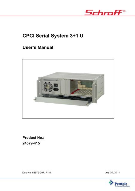
<strong>CPCI</strong> Serial System 3+1 U<br />
User’s Manual<br />
Product No.:<br />
<strong>24579</strong>-<strong>415</strong><br />
Doc-No: 63972-307_R1.0<br />
July 20, 2011
Rev. Date updated Change<br />
R1.0 July 20, 2011 Initial Release<br />
Impressum:<br />
Schroff <strong>GmbH</strong><br />
D-75334 Straubenhardt, Germany<br />
The details in this manual have been carefully compiled and<br />
checked - supported by certified Quality Management System<br />
to EN ISO 9001/2000<br />
The company cannot accept any liability for errors or misprints.<br />
The company reserves the right to amendments of technical<br />
specifications due to further development and improvement of<br />
products.<br />
Copyright2011<br />
All rights and technical modifications reserved.
<strong>CPCI</strong> Serial System 3+1 U<br />
<strong>24579</strong>-<strong>415</strong><br />
1 Safety................................................................................................................. 1<br />
1.1 Intended Application ............................................................................................ 1<br />
1.2 Safety Instructions ............................................................................................... 2<br />
1.2.1 Safety Symbols used in this document.................................................. 2<br />
1.3 General Safety Precautions................................................................................. 2<br />
2 Product Definition............................................................................................. 3<br />
2.1 References and Architecture Specifications ........................................................ 3<br />
2.2 System Overview................................................................................................. 4<br />
2.3 Subrack................................................................................................................ 4<br />
2.4 <strong>CPCI</strong> Serial Backplane ........................................................................................ 5<br />
2.4.1 Backplane topology ............................................................................... 6<br />
2.5 Power Supply....................................................................................................... 7<br />
2.5.1 ATX Power Supply................................................................................. 7<br />
2.5.2 Load Resistor......................................................................................... 8<br />
2.5.3 Grounding/Earthing................................................................................ 8<br />
2.6 Cooling................................................................................................................. 9<br />
3 Installation....................................................................................................... 10<br />
3.1 General Installation Guidelines.......................................................................... 10<br />
3.1.1 Unpacking............................................................................................ 10<br />
3.1.2 Ensuring Proper Airflow ....................................................................... 10<br />
3.2 Rack-Mounting................................................................................................... 11<br />
3.3 Initial Operation.................................................................................................. 11<br />
4 Service............................................................................................................. 12<br />
4.1 Technical support and Return for Service Assistance ....................................... 12<br />
4.2 Declaration of Conformity .................................................................................. 12<br />
4.3 Scope of Delivery............................................................................................... 13<br />
4.4 Accessories ....................................................................................................... 13<br />
4.5 Spare Parts........................................................................................................ 13<br />
5 Technical Data ................................................................................................ 14<br />
6 Dimensions ..................................................................................................... 15<br />
www.schroff.biz 1 R1.0, July 20, 2011
<strong>CPCI</strong> Serial System 3+1 U<br />
<strong>24579</strong>-<strong>415</strong><br />
www.schroff.biz 2 R1.0, July 20, 2011
<strong>CPCI</strong> Serial System 3+1 U<br />
<strong>24579</strong>-<strong>415</strong><br />
Safety<br />
1 Safety<br />
1.1 Intended Application<br />
The CompactPCI Serial system, described in this manual, is intended as a<br />
platform for a microcomputer system based on the CompactPCI Standard<br />
<strong>CPCI</strong> Serial <strong>CPCI</strong>-S.0.<br />
The case systems are designed for protection class IP 20 and can be used only<br />
in the resp. environments.<br />
<strong>CPCI</strong> system subracks are not end-products, so there is no valid approval for<br />
this unit. In order to enable stand-alone functionality, additional elements are<br />
required. An operational system is achieved only by way of appropriate <strong>CPCI</strong><br />
Serial boards.<br />
The completion and final testing of the units have been carried out, or at least<br />
supervised, by qualified technicians. These instructions are directed exclusively<br />
to these qualified technicians i.e.engineers, trained and qualified electricians<br />
etc.<br />
Make sure that:<br />
• the finished system complies with the safety regulations currently applicable<br />
in the country it is going to be used.<br />
• the finished system complies with all other regulations and specifications at<br />
the place and country of use, e.g. interference limits, approval by the telecommunications<br />
authorities.<br />
www.schroff.biz 1 R1.0, July 20, 2011
<strong>CPCI</strong> Serial System 3+1 U<br />
<strong>24579</strong>-<strong>415</strong><br />
Safety<br />
1.2 Safety Instructions<br />
The intended audience of this User’s Manual is system integrators and<br />
hardware/software engineers.<br />
1.2.1 Safety Symbols used in this document<br />
Hazardous voltage!<br />
This is the electrical hazard symbol. Familiarise yourself with the danger of<br />
electrical voltages and the safety precautions to avoid accidents before<br />
starting to work with parts that carry dangerous voltages.<br />
Caution!<br />
This is the user caution symbol. It indicates a condition where damage of the<br />
equipment or injury of the service personnel could occur. To reduce the risk of<br />
damage or injury, follow all steps or procedures as instructed.<br />
Danger of electrostatic discharge!<br />
Static electricity can damage sensitive components in a system. To avoid<br />
damage, wear ESD wrist straps or at regular intervals touch blank enclosure<br />
parts.<br />
1.3 General Safety Precautions<br />
Warning!<br />
Voltages over 60 VDC can be present in this equipment. This equipment is<br />
intended to be accessed, to be installed and maintained by qualified and<br />
trained service personnel only.<br />
This equipment is designed in accordance with protection class 1!<br />
It must therefore be operated only with protective GND/earth connection!<br />
• Service personnel must know the necessary electrical safety, wiring and<br />
connection practices for installing this equipment.<br />
• Install this equipment only in compliance with local and national electrical<br />
codes.<br />
www.schroff.biz 2 R1.0, July 20, 2011
<strong>CPCI</strong> Serial System 3+1 U<br />
<strong>24579</strong>-<strong>415</strong><br />
Product Definition<br />
2 Product Definition<br />
The Schroff <strong>CPCI</strong> Serial system consists of:<br />
• A shielded subrack with front card cage for <br />
3 U boards according to IEEE 1101.x, IEC 20297.x and the CompactPCI<br />
Standard <strong>CPCI</strong> Serial (<strong>CPCI</strong>-S.0)<br />
• A 9 slot 3 U <strong>CPCI</strong> Serial backplane with Single Star Ethernet routing,<br />
Part No.: 23007-612 (Full Mesh routing available on request)<br />
• An ATX power supply (300 W) with wide range input, IEC320-C14 connector<br />
and mains/line switch<br />
• 1 U Fan Tray with 2 axial Fans (140 m³/h (85 cfm)) for the active cooling of<br />
the boards<br />
• Drive holder for an optional slim line DVD drive<br />
• Drive holder for an optional 3.5“ HDD<br />
2.1 References and Architecture Specifications<br />
• User Guide Schroff <strong>CPCI</strong> Serial Backplanes 23007-61x<br />
Order no.: 63972-277<br />
Further information can also be found in the catalogue „Electronic Packaging“<br />
and on the internet under www.schroff.biz<br />
www.schroff.biz 3 R1.0, July 20, 2011
<strong>CPCI</strong> Serial System 3+1 U<br />
<strong>24579</strong>-<strong>415</strong><br />
Product Definition<br />
2.2 System Overview<br />
Figure 1: System Overview<br />
1 Drive holder with front panel for an 5 Front panel 3 U, 8 HP<br />
optional 3.5“ HDD<br />
2 Drive holder for an optional slim line 6 Handle<br />
DVD drive<br />
3 ATX Power Supply 7 Front Card cage with guide rails<br />
4 Fan Tray with 2 fans<br />
12311820<br />
2.3 Subrack<br />
The 4 U chassis is based on the Schroff europacPRO system with EMC<br />
shielding. The front card cage provides 9 <strong>CPCI</strong> Serial slots.<br />
The lower guide rails of the card cage are equipped with ESD clips.<br />
Variations<br />
The Schroff assembly service can customize your system with:<br />
• Different Backplane configurations<br />
• Drive mounting cassettes<br />
• Special power supplies<br />
More information in the catalogue or at www.schroff.biz<br />
www.schroff.biz 4 R1.0, July 20, 2011
<strong>CPCI</strong> Serial System 3+1 U<br />
<strong>24579</strong>-<strong>415</strong><br />
Product Definition<br />
2.4 <strong>CPCI</strong> Serial Backplane<br />
Figure 2: Backplane front and rear view<br />
1<br />
2 3 4 5 6 7 8 9<br />
IPMB<br />
UTILITY<br />
1 7<br />
1 5<br />
2 8<br />
12V<br />
GND<br />
12V<br />
GND<br />
12V<br />
GND<br />
12V<br />
GND<br />
+5V STNDBY<br />
www.schroff.biz 5 R1.0, July 20, 2011
<strong>CPCI</strong> Serial System 3+1 U<br />
<strong>24579</strong>-<strong>415</strong><br />
Product Definition<br />
2.4.1 Backplane topology<br />
The <strong>CPCI</strong> Serial backplane with 9 slots supports the full set of serial links at all<br />
slots.<br />
The serial links (SATA/SAS, USB2/3, PCIe) are arranged as a Single Star<br />
architecture.<br />
Ethernet is implemented by 4 differential pairs in Single Star routing to support<br />
10/100/1000/10GBase-T. (Full Mesh routing available on request)<br />
More information in the Schroff Backplane manual, order no.: 63972-277<br />
Figure 3: Backplane Topology<br />
23007-612 (Ethernet Single Star)<br />
Control<br />
www.schroff.biz 6 R1.0, July 20, 2011
<strong>CPCI</strong> Serial System 3+1 U<br />
<strong>24579</strong>-<strong>415</strong><br />
Product Definition<br />
Figure 4: Backplane Topology (Option)<br />
23007-611 (Ethernet Full Mesh)<br />
Control<br />
www.schroff.biz 7 R1.0, July 20, 2011
<strong>CPCI</strong> Serial System 3+1 U<br />
<strong>24579</strong>-<strong>415</strong><br />
Product Definition<br />
2.5 Power Supply<br />
Hazardous voltage!<br />
Parts of the power supply may be exposed with hazardous voltage. Always<br />
remove mains/line connector before carry out any assembly work.<br />
Caution!<br />
Power is provided through a 300 W ATX power supply with wide range input,<br />
IEC 320-C14 connector and mains on/off switch. The power supply is located at<br />
the front to the left of the card cage behind a front panel.<br />
2.5.1 ATX Power Supply<br />
Your system has not been provided with a AC power cable. Purchase a<br />
AC power cable that is approved for use in your country. The voltage and<br />
current rating of the AC power cable should be greater than the ratings marked<br />
on on the product's electrical ratings label.<br />
Table 1: Techn. Data<br />
Input voltage<br />
Input frequency<br />
90 ... 264 VAC, active PFC<br />
47...63 Hz<br />
Input current 6 A (115 V) / 3 A (230 V)<br />
Output (max) 5 V / 35 A; 3,3 V / 28 A, 12 V / 22 A, -12 V / 0,8 A)<br />
Output (min) 5 V / 0,5 A; 3,3 V / 0 A, 12 V / 0,5 A, -12 V / 0,0 A)<br />
Inrush Current<br />
Efficiency<br />
Overload protection<br />
44/87 A (115/230 VAC)<br />
>70%/75% (115/230 VAC)<br />
110...150%, switch-off<br />
Overvoltage protection +3,3 V (+3,9...+4,3 V), +5 V (+5,7...+6,5 V), +12 V (+13,6...+15 V)<br />
Ripple<br />
+3,3 V 50 mV / +5 V 50 mV / +12 V 120 mV / -12 V 150 mV<br />
Load regulation +3,3 V ±5% / +5 V ±5% / +12 V +7/-5% / -12 V ±5%<br />
Hold up time<br />
Power Good Signal<br />
Insulation Voltage<br />
Earth Leakage Current<br />
>16 msec.<br />
Power on delay 100...500 msec, Power off delay 1 msec.<br />
Input/Chassis 3100 VDC,Input/Output 4242 VDC.<br />
100.000 h at +50 °C, without fan<br />
Safety EN 60950 / UL 60950<br />
EMV<br />
Fan<br />
Dimensions<br />
CE<br />
Ball bearing fan<br />
140 x 150 x 86 mm, ±0,5mm<br />
For temperatures
<strong>CPCI</strong> Serial System 3+1 U<br />
<strong>24579</strong>-<strong>415</strong><br />
Product Definition<br />
2.5.2 Load Resistor<br />
The ATX PSU requires minimum loads at the 5 V and the 12 V outputs. Because<br />
the <strong>CPCI</strong> Serial Backplane need only 12 V supply voltage, a load resistor (10<br />
Ohms / 5 W) is connected to the 5 V output.<br />
Figure 5: Airflow<br />
12311823<br />
2.5.3 Grounding/Earthing<br />
Caution!<br />
The unit is designed in accordance with protection class 1! It must therefore be<br />
operated with protective earth/GND connection. Use only a three conductor<br />
AC power cable with a protective earth conductor that meets the IEC safety<br />
standards!<br />
www.schroff.biz 9 R1.0, July 20, 2011
<strong>CPCI</strong> Serial System 3+1 U<br />
<strong>24579</strong>-<strong>415</strong><br />
Product Definition<br />
2.6 Cooling<br />
The boards are cooled by forced air convection through two 12 VDC axial fans<br />
(140 m³/h (85 cfm)).<br />
The fans are located in a hot-swappable fan tray.<br />
The operating temperature is from 0°C to 50°C.<br />
Caution!<br />
To maintain proper airflow, all open slots must be covered with filler panels.<br />
The filler panel should include an airflow baffle that extends to backplane.<br />
Figure 6: Airflow<br />
12308833<br />
www.schroff.biz 10 R1.0, July 20, 2011
<strong>CPCI</strong> Serial System 3+1 U<br />
<strong>24579</strong>-<strong>415</strong><br />
Installation<br />
3 Installation<br />
3.1 General Installation Guidelines<br />
3.1.1 Unpacking<br />
Caution!<br />
When opening the shipping carton, use caution to avoid damaging the system.<br />
Consider the following when unpacking and storing the system:<br />
• Leave the system packed until it is needed for immediate installation.<br />
• After unpacking the system, save and store the packaging material in case<br />
the system must be returned.<br />
If the packaging is damaged and possible system damage is present, report to<br />
the shipper and analyze the damage.<br />
3.1.2 Ensuring Proper Airflow<br />
• Maintain ambient airflow to ensure normal operation. If the airflow is blocked<br />
or restricted, or if the intake air is too warm, an over temperature condition<br />
can occur.<br />
• Ensure that cables from other equipment do not obstruct the airflow through<br />
the systems.<br />
• Use filler panels to cover all empty chassis slots. The filler panel should<br />
include an airflow baffle that extends to backplane. The filler panel prevents<br />
fan air from escaping out of the front of an open slot.<br />
Filler Panels and Air Baffles<br />
Air baffles and front panels with air baffles are available in the Schroff catalogue<br />
or at www.schroff.biz<br />
www.schroff.biz 11 R1.0, July 20, 2011
<strong>CPCI</strong> Serial System 3+1 U<br />
<strong>24579</strong>-<strong>415</strong><br />
Installation<br />
3.2 Rack-Mounting<br />
This subrack system can be installed in 19“ equipment racks. The rack must be<br />
accessible from the front and rear for equipment installation.<br />
Mounting Kit<br />
3.3 Initial Operation<br />
A rack mounting kit comes with the system.<br />
Mounting Instructions:<br />
• Ensure that the rack is constructed to support the weight and dimensions of<br />
the system.<br />
• Install any stabilizers that came with your equipment rack before mounting<br />
or servicing the system in the rack.<br />
Load the rack from the bottom to the top, with the heaviest system at the bottom,<br />
avoid uneven mechanical loading of the rack.<br />
Warning!<br />
This equipment is intended to be accessed, to be installed and maintained by<br />
qualified and trained service personnel only.<br />
This equipment is designed in accordance with protection class 1!<br />
It must therefore be operated only with protective GND/earth connection!<br />
• Ensure that the system has not been damaged during transport, storage or<br />
assembly.<br />
• Check the Protective Earth (PE) resistance, should be < 0,1 Ohm.<br />
• Switch on the system and check the supply voltage directly on the<br />
backplane connectors before the board assembly.<br />
Note: The ATX power supply requires a minimum load!<br />
• Plug-in the boards<br />
• Cover all open Slots with filler panels.<br />
www.schroff.biz 12 R1.0, July 20, 2011
<strong>CPCI</strong> Serial System 3+1 U<br />
<strong>24579</strong>-<strong>415</strong><br />
Service<br />
4 Service<br />
4.1 Technical support and Return for Service Assistance<br />
We generally recommend to return the complete system. For all product returns<br />
and support issues, please contact your Schroff sales distributor or<br />
www.schroff.biz.<br />
We recommend that you save the packing material. Shipping without the original<br />
packing material might void the warranty.<br />
4.2 Declaration of Conformity<br />
SCHROFF CompactPCI systems are developed and manufactured according<br />
to EN 60950-1.<br />
SCHROFF CompactPCI systems are not end-products with independent<br />
functionality as described in the definition of the EMC regulations, and therefore<br />
a CE marking is not required. However, when <strong>CPCI</strong> Serial cards are assembled<br />
according to specification, the systems fulfill the requirements in accordance<br />
with EMC Directive 2004/108/EG and Low-voltage Directive<br />
2006/95/EG.<br />
Interference resistance and interference emissions are factors which are heavily<br />
influenced by the type and quantity of <strong>CPCI</strong> cards used in the system assembly.<br />
Through the use of high quality line filters and EMC optimized enclosure design,<br />
SCHROFF offers <strong>CPCI</strong> systems which serve as an ideal base for system<br />
integrators, which comply with the prescribed limits of EN 6100-6-3 and<br />
EN 61000-6-2<br />
The systems are generally equipped with power supplies which possess<br />
CE markings in accordance with EN 60950-1, EN 61000-6-3, EN 61000-6-2).<br />
Before delivery a high-voltage, protective earth and functionality test is carried<br />
out on each individual system.<br />
www.schroff.biz 13 R1.0, July 20, 2011
<strong>CPCI</strong> Serial System 3+1 U<br />
<strong>24579</strong>-<strong>415</strong><br />
Service<br />
4.3 Scope of Delivery<br />
Quantity<br />
Description<br />
1 Shielded europacPRO chassis 4 U / 84 HP with front handles<br />
1 <strong>CPCI</strong> Serial backplane 9 slot 3 U with Single Star Ethernet topology<br />
1 Front card cage for max. 9 boards 3 U 160 mm deep<br />
IEEE guide rails inc. ESD clips)<br />
1 300 W ATX power supply with input range of 100 VAC to 240 VAC, IEC320-C14 connector and<br />
mains/line switch.<br />
12 V / 22 A<br />
1 Complete AC/DC cabling<br />
1 Fan Tray 1 HP with 2 fans 140 m³/h (85 cfm) each<br />
1 Drive holder for a slim line DVD drive<br />
1 Drive holder with front panel 3 U, 8 HP for a 3,5“ HDD<br />
1 Front panel 3 U, 8 HP<br />
1 Front panel 3 U, 84 HP<br />
1 19“ rack mounting kit<br />
Please order the power cable separately.<br />
4.4 Accessories<br />
Order No.<br />
Description<br />
20848-75x Front panels for Rear I/O Boards, dimensions see catalogue<br />
<strong>24579</strong>-033 Air filter kit<br />
20848-7xx<br />
34562-8xx<br />
Slot covers with front panel and EMC shielding for vacant slots. For dimensions, please see<br />
catalogue.<br />
Slot covers for vacant slots. For dimensions, please see catalogue.<br />
<strong>24579</strong>-03x Printed Circuit Board covers (solder side covers). For dimensions, please see catalogue<br />
4.5 Spare Parts<br />
On request.<br />
www.schroff.biz 14 R1.0, July 20, 2011
<strong>CPCI</strong> Serial System 3+1 U<br />
<strong>24579</strong>-<strong>415</strong><br />
Technical Data<br />
5 Technical Data<br />
Table 2: Technical Data<br />
Dimensions<br />
Height 4 U<br />
Width 482.60 mm (19“)<br />
Depth (Card cage)<br />
Depth (Overall with handles)<br />
Weight<br />
275 mm<br />
322 mm<br />
Completely assembled approx. 7,5 kg<br />
Power Supply<br />
Input Voltage 100 VAC to 240 VAC<br />
Frequency 50 / 60 Hz<br />
Power input<br />
Cooling<br />
up to 300 W<br />
2 x 12 VDC fans 140 m³/h (85 cfm) each, free blow<br />
Ambient Temperature<br />
Operation +0 °C to +50 °C<br />
Storage -40 °C to +85 °C<br />
Humidity<br />
Admissible humidity 30 % to 80 %, non-condensing<br />
EMC, fulfils requirements for:<br />
Transient Emissions EN 61000-6-3<br />
Interference Resistance EN 61000-6-2<br />
Safety<br />
Test voltages according to EN 60950 Input - Output:<br />
Input - PE:<br />
Output - PE:<br />
Output - Output:<br />
4,3 kVDC<br />
2,2 kVDC<br />
0,7 kVDC<br />
0,7 kVDC<br />
Shock and vibration: EN 60068-2-6 and EN 60068-2-27<br />
Electromagnetic Shielding<br />
Shielding attenuation<br />
typ. 40 dB at 1 GHz if shielded front<br />
panels are used.<br />
www.schroff.biz 15 R1.0, July 20, 2011
<strong>CPCI</strong> Serial System 3+1 U<br />
<strong>24579</strong>-<strong>415</strong><br />
Dimensions<br />
6 Dimensions<br />
Figure 7: Dimensions<br />
www.schroff.biz 16 R1.0, July 20, 2011
SCHROFF GMBH<br />
www.schroff.biz<br />
Langenalberstr. 96-100 Tel.: + 49 (0) 7082 794-0 Fax: +49 (0) 7082 794-200<br />
D-75334 Straubenhardt