Operating Instructions Fan Control Module (FCM) - Secomp GmbH
Operating Instructions Fan Control Module (FCM) - Secomp GmbH
Operating Instructions Fan Control Module (FCM) - Secomp GmbH

Create successful ePaper yourself
Turn your PDF publications into a flip-book with our unique Google optimized e-Paper software.
<strong>Operating</strong> <strong>Instructions</strong><br />
<strong>Fan</strong> <strong>Control</strong> <strong>Module</strong> (<strong>FCM</strong>)<br />
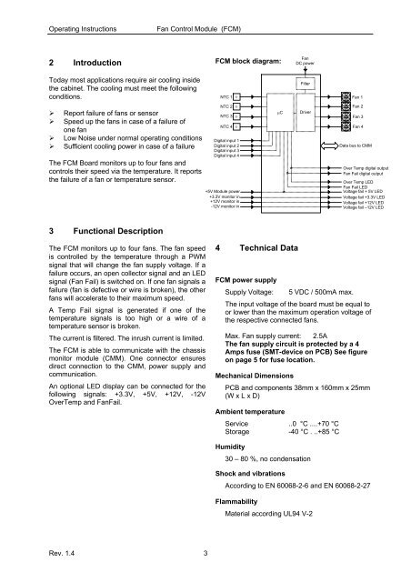
2 Introduction<br />
<strong>FCM</strong> block diagram:<br />
<strong>Fan</strong><br />
DC power<br />
Today most applications require air cooling inside<br />
the cabinet. The cooling must meet the following<br />
conditions.<br />
NTC 1<br />
υ<br />
Filter<br />
<strong>Fan</strong> 1<br />
‣ Report failure of fans or sensor<br />
‣ Speed up the fans in case of a failure of<br />
one fan<br />
‣ Low Noise under normal operating conditions<br />
‣ Sufficient cooling power in case of a failure<br />
The <strong>FCM</strong> Board monitors up to four fans and<br />
controls their speed via the temperature. It reports<br />
the failure of a fan or temperature sensor.<br />
NTC 2 υ<br />
NTC 3 υ<br />
NTC 4 υ<br />
Digital input 1<br />
Digital input 2<br />
Digital input 3<br />
Digital input 4<br />
+5V <strong>Module</strong> power<br />
+3.3V monitor in<br />
+12V monitor in<br />
-12V monitor in<br />
μC<br />
Driver<br />
<strong>Fan</strong> 2<br />
<strong>Fan</strong> 3<br />
<strong>Fan</strong> 4<br />
Data bus to CMM<br />
Over Temp digital output<br />
<strong>Fan</strong> Fail digital output<br />
Over Temp LED<br />
<strong>Fan</strong> Fail LED<br />
Voltage fail + 5V LED<br />
Voltage fail +3.3V LED<br />
Voltage fail +12V LED<br />
Voltage fail –12V LED<br />
3 Functional Description<br />
The <strong>FCM</strong> monitors up to four fans. The fan speed<br />
is controlled by the temperature through a PWM<br />
signal that will change the fan supply voltage. If a<br />
failure occurs, an open collector signal and an LED<br />
signal (<strong>Fan</strong> Fail) is switched on. If one fan signals a<br />
failure (fan is defective or wire is broken), the other<br />
fans will accelerate to their maximum speed.<br />
A Temp Fail signal is generated if one of the<br />
temperature signals is too high or a wire of a<br />
temperature sensor is broken.<br />
The current is filtered. The inrush current is limited.<br />
The <strong>FCM</strong> is able to communicate with the chassis<br />
monitor module (CMM). One connector ensures<br />
direct connection to the CMM, power supply and<br />
communication.<br />
An optional LED display can be connected for the<br />
following signals: +3.3V, +5V, +12V, -12V<br />
OverTemp and <strong>Fan</strong>Fail.<br />
4 Technical Data<br />
<strong>FCM</strong> power supply<br />
Supply Voltage: 5 VDC / 500mA max.<br />
The input voltage of the board must be equal to<br />
or lower than the maximum operation voltage of<br />
the respective connected fans.<br />
Max. <strong>Fan</strong> supply current: 2.5A<br />
The fan supply circuit is protected by a 4<br />
Amps fuse (SMT-device on PCB) See figure<br />
on page 5 for fuse location.<br />
Mechanical Dimensions<br />
PCB and components 38mm x 160mm x 25mm<br />
(W x L x D)<br />
Ambient temperature<br />
Service ..0 °C ....+70 °C<br />
Storage -40 °C . ..+85 °C<br />
Humidity<br />
30 – 80 %, no condensation<br />
Shock and vibrations<br />
According to EN 60068-2-6 and EN 60068-2-27<br />
Flammability<br />
Material according UL94 V-2<br />
Rev. 1.4 3