MA series, MB series Jumper setting
MA series, MB series Jumper setting
MA series, MB series Jumper setting

Create successful ePaper yourself
Turn your PDF publications into a flip-book with our unique Google optimized e-Paper software.
<strong>MA</strong> Series, <strong>MB</strong> Series <strong>Jumper</strong> Setting<br />
1. Object Model<br />
<strong>MA</strong>P3147NC <strong>MA</strong>S3184NC <strong>MA</strong>T3073NC <strong>MA</strong>U3036NC<br />
<strong>MA</strong>P3147NP <strong>MA</strong>S3184NP <strong>MA</strong>T3073NP <strong>MA</strong>U3036NP<br />
<strong>MA</strong>P3367NC <strong>MA</strong>S3367NC <strong>MA</strong>T3147NC <strong>MA</strong>U3073NC<br />
<strong>MA</strong>P3367NP <strong>MA</strong>S3367NP <strong>MA</strong>T3147NP <strong>MA</strong>U3073NP<br />
<strong>MA</strong>P3735NC <strong>MA</strong>S3735NC <strong>MA</strong>T3300NC <strong>MA</strong>U3147NC<br />
<strong>MA</strong>P3735NP <strong>MA</strong>S3735NP <strong>MA</strong>T3300NP <strong>MA</strong>U3147NP<br />
<strong>MA</strong>W3073NC <strong>MA</strong>X3036NC <strong>MB</strong>A3073NC<br />
<strong>MA</strong>W3073NP <strong>MA</strong>X3036NP <strong>MB</strong>A3073NP<br />
<strong>MA</strong>W3147NC <strong>MA</strong>X3073NC <strong>MB</strong>A3147NC<br />
<strong>MA</strong>W3147NP <strong>MA</strong>X3073NP <strong>MB</strong>A3147NP<br />
<strong>MA</strong>W3300NC <strong>MA</strong>X3147NC <strong>MB</strong>A3300NC<br />
<strong>MA</strong>W3300NP <strong>MA</strong>X3147NP <strong>MB</strong>A3300NP<br />
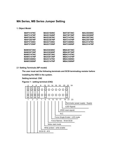
2.1 Setting Terminals (NP model)<br />
The user must set the following terminals and SCSI terminating resistor before<br />
installing the HDD in the system.<br />
Setting terminal: CN2<br />
Figures 1 : <strong>setting</strong> terminal (CN2)<br />
2 4 6 8 10 12 14 16 18 20 22 24<br />
1 3 5 7 9 11 13 15 17 19 21 23<br />
Terminator power supply : Supply<br />
<br />
(LED Signal)<br />
(HDD reset signal)<br />
N.C.<br />
Force Single Ended : LVD mode<br />
Force Narrow : 16-bit SCSI<br />
Motor start mode<br />
Write protect : write enable<br />
SCSI ID : #15
2.2 CAUTION (NP model):<br />
1. The user must not change the <strong>setting</strong> of terminals not described in this section. Do not<br />
change <strong>setting</strong> status set at factory shipment.<br />
2. Do not change the <strong>setting</strong> of terminals except following <strong>setting</strong> pins during the power is<br />
turned on. - Write protect: CN2 9-10<br />
3. To short the <strong>setting</strong> terminal, use the short plug attached when the device is shipped<br />
from the factory.<br />
2.3 SCSI ID <strong>setting</strong> (NP model)<br />
Table 1 shows the SCSI ID <strong>setting</strong>. Refer to Figure 1 for connector position.<br />
IMPORTANT<br />
When the SCSI ID is set using the external operator panel connector CN1, all pins<br />
listed in Table 1 should be open. If any of pins are shorted, unexpected SCSI is set.<br />
1. Set the SCSI ID so that there are no duplicates between SCSI devices on the same<br />
SCSI bus.<br />
2. The priority of SCSI bus use in ARBITRATION phase is determined by SCSI ID as<br />
follows:<br />
7>6>5>4>3>2>1>0>15>14>13>12>11>10>9>8<br />
Table 1 SCSI ID <strong>setting</strong><br />
SCSI ID<br />
CN2<br />
1-2 3-4 5-6 7-8<br />
0 OPEN OPEN OPEN OPEN<br />
1 SHORT OPEN OPEN OPEN<br />
2 OPEN SHORT OPEN OPEN<br />
3 SHORT SHORT OPEN OPEN<br />
4 OPEN OPEN SHORT OPEN<br />
5 SHORT OPEN SHORT OPEN<br />
6 OPEN SHORT SHORT OPEN<br />
7 SHORT SHORT SHORT OPEN<br />
8 OPEN OPEN OPEN SHORT<br />
9 SHORT OPEN OPEN SHORT<br />
10 OPEN SHORT OPEN SHORT<br />
11 SHORT SHORT OPEN SHORT<br />
12 OPEN OPEN SHORT SHORT<br />
13 SHORT OPEN SHORT SHORT<br />
14 OPEN SHORT SHORT SHORT<br />
15 * SHORT SHORT SHORT SHORT<br />
* Setting at factory shipment
2.4 Setting terminal power supply (NP model)<br />
Refer to Table 2 for controlling the supply of power from the drive to SCSI terminal<br />
resistance power source (TERMPOW). However, this <strong>setting</strong> may not be used with NC<br />
model. For information on NP type model, refer to Figure 1.<br />
Table 2 Setting SCSI terminator power supply (NP model only)<br />
Supply on/off of SCSI terminator power from HDD CN2 23-24<br />
Supply off<br />
OPEN<br />
Supply on SHORT *<br />
* Setting at factory shipment<br />
2.5 Motor start mode (NP model)<br />
Set how to control the starting of the HDD spindle motor according to Table 3. This <strong>setting</strong><br />
only determines the operation mode when the power supply is turned on. The stopping or<br />
restarting the spindle motor can be controlled by specifying the START/STOP UNIT<br />
command.<br />
Table 3 Motor start mode <strong>setting</strong> (NP model only)<br />
Start timing of the spindle motor CN2 11-12<br />
Starting of the motor is controlled with<br />
OPEN<br />
START/STOP UNIT<br />
command.<br />
The motor is started immediately after the power SHORT *<br />
supply is turned on.<br />
* Setting at factory shipment<br />
2.6 Write protect (NP model)<br />
When the write protect function is enabled, writing to the disk medium is disabled.<br />
Table 4 Write protect <strong>setting</strong><br />
Write protect CN2 9-10<br />
Write operation is enabled. OPEN *<br />
Write operation is disable.<br />
SHORT<br />
* Setting at factory shipment
2.7 Setting of the SCSI interface operation mode (NP model)<br />
By establishing a short-circuit between the 13 and 14 CN2 <strong>setting</strong> terminals, the bus width<br />
for the SCSI interface is forcibly set to the 8-bit bus mode. The setup terminal must be set<br />
in order to guarantee the physical level of the SCSI interface's upper bus (DB8-15, P1)<br />
inside the HDD only when the top-level bus (DB8-15, P1) for the HDD SCSI interface is not<br />
connected to the external part of the HDD.<br />
Table 5 Setting of the SCSI interface operation mode<br />
Operation mode CN2 15-16<br />
Follows the DIFFSNS signal level on the SCSI bus OPEN *<br />
Single-Ended mode.<br />
SHORT<br />
* Setting at factory shipment<br />
2.8 Setting the bus width of the SCSI interface (NP model)<br />
By establishing a short-circuit between the 13 and 14 CN2 <strong>setting</strong> terminals, the bus width<br />
for the SCSI interface is forcibly set to the 8-bit bus mode. The setup terminal must be set<br />
in order to guarantee the physical level of the SCSI interface's upper bus (DB8-15, P1)<br />
inside the HDD only when the top-level bus (DB8-15, P1) for the HDD SCSI interface is not<br />
connected to the external part of the HDD.<br />
Table 6 Setting the bus width of the SCSI interface<br />
Bus width CN2 13-14<br />
16 bit bus OPEN *<br />
8 bit bus SHORT<br />
* Setting at factory shipment
3. Mode <strong>setting</strong>s : NC model, NP model<br />
In addition to the previously described <strong>setting</strong>s using <strong>setting</strong> terminals, the HDD is<br />
provided with several mode <strong>setting</strong>s. The mode <strong>setting</strong>s are enabled by specifying the<br />
CHANGE DEFINITION command. Table 7 lists the mode <strong>setting</strong>s and their <strong>setting</strong>s at<br />
factory shipment.<br />
Table 7 Default mode <strong>setting</strong>s (by CHANGE DEFINITION command)<br />
Mode <strong>setting</strong> Contents *<br />
SCSI level Refer to Table 8 or Table 9<br />
SYNCHRONOUS DATA TRANSFER REQUEST Not Sent from HDD<br />
message sending<br />
UNIT ATTENTION report mode<br />
Reported<br />
Reselection retry count<br />
Not restricted<br />
WIDE DATA TRANSFER REQUEST message Not Sent from HDD<br />
sending<br />
Reselection time-out delay<br />
250ms<br />
Spindle motor start delay time<br />
0 second (NP)<br />
12 seconds x SCSI ID (NC)<br />
* Setting at factory shipment<br />
Table 8 : SCSI-2 product<br />
<strong>MA</strong>P3147NC <strong>MA</strong>S3184NC <strong>MA</strong>T3073NC <strong>MA</strong>U3036NC<br />
<strong>MA</strong>P3147NP <strong>MA</strong>S3184NP <strong>MA</strong>T3073NP <strong>MA</strong>U3036NP<br />
<strong>MA</strong>P3367NC <strong>MA</strong>S3367NC <strong>MA</strong>T3147NC <strong>MA</strong>U3073NC<br />
<strong>MA</strong>P3367NP <strong>MA</strong>S3367NP <strong>MA</strong>T3147NP <strong>MA</strong>U3073NP<br />
<strong>MA</strong>P3735NC <strong>MA</strong>S3735NC <strong>MA</strong>T3300NC <strong>MA</strong>U3147NC<br />
<strong>MA</strong>P3735NP <strong>MA</strong>S3735NP <strong>MA</strong>T3300NP <strong>MA</strong>U3147NP<br />
Table 9 : SCSI-3 product<br />
<strong>MA</strong>W3073NC <strong>MA</strong>X3036NC <strong>MB</strong>A3073NC<br />
<strong>MA</strong>W3073NP <strong>MA</strong>X3036NP <strong>MB</strong>A3073NP<br />
<strong>MA</strong>W3147NC <strong>MA</strong>X3073NC <strong>MB</strong>A3147NC<br />
<strong>MA</strong>W3147NP <strong>MA</strong>X3073NP <strong>MB</strong>A3147NP<br />
<strong>MA</strong>W3300NC <strong>MA</strong>X3147NC <strong>MB</strong>A3300NC<br />
<strong>MA</strong>W3300NP <strong>MA</strong>X3147NP <strong>MB</strong>A3300NP