CAN FD Protocol Specification - Bosch Semiconductors and Sensors
CAN FD Protocol Specification - Bosch Semiconductors and Sensors
CAN FD Protocol Specification - Bosch Semiconductors and Sensors

You also want an ePaper? Increase the reach of your titles
YUMPU automatically turns print PDFs into web optimized ePapers that Google loves.
<strong>CAN</strong> with Flexible Data-Rate<br />
<strong>Specification</strong><br />
Version 1.0<br />
(released April 17th, 2012)<br />
<strong>FD</strong>
April 2012<br />
page 1<br />
Recital<br />
The acceptance <strong>and</strong> introduction of serial communication to more <strong>and</strong> more applications<br />
has led to increasing dem<strong>and</strong> for b<strong>and</strong>width in <strong>CAN</strong> communication <strong>and</strong> caused<br />
system developers to look for alternative communication options in certain applications.<br />
These applications can be realized more comfortably with the new protocol <strong>CAN</strong> <strong>FD</strong><br />
that allows data rates higher than 1 MBit/s <strong>and</strong> payloads longer 8 bytes per frame.<br />
<strong>CAN</strong> <strong>FD</strong> shares the physical layer, with the <strong>CAN</strong> protocol as defined in the BOSCH<br />
<strong>CAN</strong> <strong>Specification</strong> 2.0. The frame format however, is different. There are two new control<br />
bits in the <strong>CAN</strong> <strong>FD</strong> frame, the first enabling the new frame format with different data<br />
length coding <strong>and</strong> the second optionally switching to a faster bit rate after the arbitration<br />
is decided. New CRC polynomials are introduced to secure the longer <strong>CAN</strong> <strong>FD</strong> frames<br />
with the same Hamming distance as in the proven <strong>CAN</strong> protocol.<br />
The <strong>CAN</strong> <strong>FD</strong> frame format has been defined so that messages in <strong>CAN</strong> frame format<br />
<strong>and</strong> in <strong>CAN</strong> <strong>FD</strong> frame format can coexist within the same network. The BOSCH <strong>CAN</strong><br />
<strong>Specification</strong> 2.0 remains valid without any modification as an independent, self-contained<br />
<strong>CAN</strong> bus protocol specification. The coexistence is assured by the requirement,<br />
that in order to be compatible with this <strong>CAN</strong> <strong>FD</strong> specification it is required that a<br />
<strong>CAN</strong> <strong>FD</strong> implementation be compatible with this <strong>CAN</strong> <strong>FD</strong> specification as well as with<br />
the BOSCH <strong>CAN</strong> <strong>Specification</strong> 2.0.<br />
In order to be compatible with this <strong>CAN</strong> <strong>FD</strong> specification it is required that a <strong>CAN</strong> <strong>FD</strong><br />
implementation be compatible with this specification as well as with ISO 11898-1.<br />
Note: <strong>CAN</strong> <strong>FD</strong> implementations that are designed according to this specification <strong>and</strong><br />
<strong>CAN</strong> implementations that are designed according to the BOSCH <strong>CAN</strong> <strong>Specification</strong> 2.0<br />
can communicate with each other as long as it is not made use of the <strong>CAN</strong> <strong>FD</strong> frame<br />
format. This enables <strong>CAN</strong> systems to migrate gradually into <strong>CAN</strong> <strong>FD</strong> systems. In the<br />
introductory phase, it is possible to use <strong>CAN</strong> <strong>FD</strong> only in specific operation modes, e.g.<br />
software-download at end-of-line programming, while other controllers that do not support<br />
<strong>CAN</strong> <strong>FD</strong> are kept in st<strong>and</strong>by.<br />
© Copyright 2011, Robert <strong>Bosch</strong> GmbH, Robert <strong>Bosch</strong> Platz 1, 70839 Gerlingen, Germany
April 2012<br />
page 2<br />
1 Introduction ............................................................................................................ 3<br />
2 Basic Concepts...................................................................................................... 5<br />
3 Message Transfer.................................................................................................. 8<br />
3.1 Frame Formats ...................................................................................................... 8<br />
3.2 Frame Types.......................................................................................................... 8<br />
3.3 Operation Modes ................................................................................................. 19<br />
4 Message Validation ............................................................................................. 21<br />
4.1 Message Filtering ................................................................................................ 21<br />
5 Coding ................................................................................................................. 22<br />
6 Error H<strong>and</strong>ling...................................................................................................... 23<br />
6.1 Error Detection..................................................................................................... 23<br />
6.2 Error Signalling .................................................................................................... 23<br />
7 Fault Confinement ............................................................................................... 24<br />
8 Bit Timing Requirements ..................................................................................... 26<br />
8.1 Transceiver Delay Compensation........................................................................ 30<br />
9 <strong>CAN</strong> <strong>FD</strong> Implementation...................................................................................... 32<br />
© Copyright 2011, Robert <strong>Bosch</strong> GmbH, Robert <strong>Bosch</strong> Platz 1, 70839 Gerlingen, Germany
Introduction<br />
April 2012<br />
page 3<br />
1 INTRODUCTION<br />
<strong>CAN</strong> <strong>FD</strong> is a serial communications protocol which efficiently supports distributed realtime<br />
control with a very high level of security.<br />
The intention of this specification is to achieve compatibility between any two <strong>CAN</strong> <strong>FD</strong><br />
implementations. Compatibility, however, has different aspects regarding e.g. electrical<br />
features <strong>and</strong> the interpretation of data to be transferred. To achieve design transparency<br />
<strong>and</strong> implementation flexibility <strong>CAN</strong> <strong>FD</strong> has been subdivided into different layers<br />
according to the ISO/OSI Reference Model.<br />
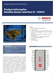
Layered Architecture of <strong>CAN</strong> <strong>FD</strong> according to the OSI Reference Model<br />
Data Link Layer<br />
LLC<br />
Logical Link Control<br />
Acceptance Filtering<br />
Overload Notification<br />
Recovery Management<br />
MAC Medium Access Control<br />
Data Encapsulation<br />
/Decapsulation<br />
Frame Coding<br />
(Stuffing, Destuffing)<br />
Medium Access Management<br />
Error Detection<br />
Error Signalling<br />
Acknowledgment<br />
Serialization / Deserialization<br />
Supervisor<br />
Fault<br />
Confinement<br />
Physical Layer<br />
Bit Encoding/Decoding<br />
Bit Timing<br />
Synchronization<br />
Bus Failure<br />
Management<br />
Driver/Receiver Characteristics<br />
The scope of this specification is to define the MAC sublayer <strong>and</strong> a small part of the<br />
LLC sublayer of the Data Link Layer as well a part of the Physical Layer <strong>and</strong> to describe<br />
the consequences of the <strong>CAN</strong> protocol on the surrounding layers.<br />
© Copyright 2011, Robert <strong>Bosch</strong> GmbH, Robert <strong>Bosch</strong> Platz 1, 70839 Gerlingen, Germany
April 2012<br />
page 4<br />
Introduction<br />
Data Link Layer<br />
The Data Link Layer h<strong>and</strong>les frames <strong>and</strong> consists of the two sublayers:<br />
• Logical Link Control (LLC)<br />
• Medium Access Control (MAC)<br />
LLC sublayer of the Data Link Layer<br />
The LLC corresponds to the node’s controller-host interface <strong>and</strong> is concerned with Message<br />
Filtering, Overload Notification <strong>and</strong> Recovery Management. Its scope is<br />
• to decide which messages received by the MAC sublayer are actually to be<br />
accepted,<br />
• to provide services for data transfer <strong>and</strong> for remote data request,<br />
• to provide messages to the MAC sublayer for transmission,<br />
• to provide means for recovery management <strong>and</strong> overload notifications.<br />
There is much freedom in defining object h<strong>and</strong>ling.<br />
MAC sublayer of the Data Link Layer<br />
The MAC sublayer is responsible for Message Framing, Arbitration, Acknowledgment,<br />
Error Detection <strong>and</strong> Signalling. It is supervised by a management entity called Fault<br />
Confinement which is a self-checking mechanism for distinguishing short disturbances<br />
from permanent failures. Within the MAC sublayer it is decided whether the bus is free<br />
for starting a new transmission or whether a reception is just starting. The MAC sublayer<br />
represents the kernel of the <strong>CAN</strong> <strong>FD</strong> protocol. It is in the nature of the MAC sublayer<br />
that there is no freedom for modifications.<br />
Physical Layer<br />
The Physical Layer h<strong>and</strong>les bits <strong>and</strong> defines how signals are actually transmitted <strong>and</strong><br />
therefore deals with the description of Bit Timing, Bit Encoding, <strong>and</strong> Synchronization.<br />
Within this specification the electrical driver/receiver characteristics of the Physical<br />
Layer are not defined so as to allow transmission medium <strong>and</strong> signal level implementations<br />
to be optimized for their application.<br />
Within one network the Physical Layer, of course, has to be the same for all nodes.<br />
There may be, however, much freedom in selecting a Physical Layer.<br />
© Copyright 2011, Robert <strong>Bosch</strong> GmbH, Robert <strong>Bosch</strong> Platz 1, 70839 Gerlingen, Germany
Basic Concepts<br />
April 2012<br />
page 5<br />
2 BASIC CONCEPTS<br />
<strong>CAN</strong> <strong>FD</strong> has the following properties<br />
• prioritization of messages<br />
• guarantee of latency times<br />
• configuration flexibility<br />
• multicast reception with time synchronization<br />
• system wide data consistency<br />
• multimaster<br />
• error detection <strong>and</strong> signalling<br />
• automatic retransmission of corrupted messages as soon as the bus is idle again<br />
• distinction between temporary errors <strong>and</strong> permanent failures of nodes <strong>and</strong><br />
autonomous switching off of defect nodes<br />
• compatibility with <strong>CAN</strong> protocol, every <strong>CAN</strong> <strong>FD</strong> node is able to receive <strong>and</strong> to<br />
transmit <strong>CAN</strong> messages according to ISO 11898-1.<br />
Messages<br />
Information on the bus is sent in fixed format messages of different but limited length<br />
(see section 3: Message Transfer). When the bus is free, any connected unit may start<br />
to transmit a new message.<br />
Information Routing<br />
In <strong>CAN</strong> <strong>FD</strong> systems a node does not make use of any information about the system<br />
configuration (e.g. station addresses). This has several important consequences.<br />
System Flexibility: Nodes can be added to the <strong>CAN</strong> <strong>FD</strong> network without requiring<br />
any change in the software or hardware of any node <strong>and</strong> application layer.<br />
Message Routing: The content of a message is named by an IDENTIFIER. The<br />
IDENTIFIER does not indicate the destination of the message, but describes the<br />
meaning of the data, so that all nodes in the network are able to decide by<br />
Message Filtering whether the data is to be acted upon by them or not.<br />
Multicast: As a consequence of the concept of Message Filtering any number of<br />
nodes can receive <strong>and</strong> simultaneously act upon the same message.<br />
Data Consistency: Within a <strong>CAN</strong> <strong>FD</strong> network it is guaranteed that a message is<br />
simultaneously accepted either by all nodes or by no node. Thus data<br />
consistency is achieved by the concepts of multicast <strong>and</strong> by error h<strong>and</strong>ling.<br />
Bit rate<br />
There may be two bit rates in a <strong>CAN</strong> <strong>FD</strong> system, one for the ARBITRATION-PHASE <strong>and</strong><br />
one for the DATA-PHASE. The speed of <strong>CAN</strong> <strong>FD</strong> may be different in different systems.<br />
However, in a given system the two bit rates are uniform <strong>and</strong> fixed.<br />
Priorities<br />
The IDENTIFIER defines a static message priority during bus access.<br />
© Copyright 2011, Robert <strong>Bosch</strong> GmbH, Robert <strong>Bosch</strong> Platz 1, 70839 Gerlingen, Germany
April 2012<br />
page 6<br />
Basic Concepts<br />
Remote Data Request<br />
By sending a REMOTE FRAME a node requiring data may request another node to send<br />
the corresponding DATA FRAME. The DATA FRAME <strong>and</strong> the corresponding REMOTE<br />
FRAME are named by the same IDENTIFIER. There is no REMOTE FRAME in the <strong>CAN</strong> <strong>FD</strong><br />
format. Each <strong>CAN</strong> <strong>FD</strong> node however is able to transmit a REMOTE FRAME in the st<strong>and</strong>ard<br />
<strong>CAN</strong> format.<br />
Multimaster<br />
When the bus is free any unit may start to transmit a message. The unit with the started<br />
message of higher priority gains bus access.<br />
Arbitration<br />
Whenever the bus is free, any unit may start to transmit a message. If two or more units<br />
start transmitting messages at the same time, the bus access conflict is resolved by bitwise<br />
arbitration using the IDENTIFIER. The mechanism of arbitration guarantees that neither<br />
information nor time is lost. If a DATA FRAME <strong>and</strong> a REMOTE FRAME with the same<br />
IDENTIFIER are initiated at the same time, the DATA FRAME prevails over the REMOTE<br />
FRAME. During arbitration every transmitter compares the level of the bit transmitted with<br />
the level that is monitored on the bus. If these levels are equal the unit may continue to<br />
send. When a recessive level is sent <strong>and</strong> a dominant level is monitored (see Bus Values),<br />
the unit has lost arbitration <strong>and</strong> must withdraw without sending one more bit.<br />
Safety<br />
In order to achieve the utmost safety of data transfer, powerful measures for error<br />
detection, signalling <strong>and</strong> self-checking are implemented in every <strong>CAN</strong> <strong>FD</strong> node.<br />
• Error Detection<br />
For detecting errors the following measures have been taken:<br />
- Monitoring (transmitters compare the bit levels to be transmitted with the<br />
bit levels detected on the bus)<br />
- Cyclic Redundancy Check<br />
- Bit Stuffing<br />
- Message Frame Check<br />
• Performance of Error Detection<br />
The error detection mechanisms have the following properties:<br />
- all global errors are detected.<br />
- all local errors at transmitters are detected.<br />
- up to 5 r<strong>and</strong>omly distributed errors in a message are detected.<br />
- burst errors of length less than CRC Sequence in a message are detected.<br />
- errors of any odd number in a message are detected.<br />
Total residual error probability for undetected corrupted messages: less than<br />
message error rate * 4.7 * 10 -11 .<br />
© Copyright 2011, Robert <strong>Bosch</strong> GmbH, Robert <strong>Bosch</strong> Platz 1, 70839 Gerlingen, Germany
Basic Concepts<br />
April 2012<br />
page 7<br />
Error Signalling <strong>and</strong> Recovery Time<br />
Corrupted messages are flagged by any node detecting an error. Such messages are<br />
aborted <strong>and</strong> will be retransmitted automatically. The recovery time from detecting an<br />
error until the restart of the disturbed message is at most 31 bit times, if there is no further<br />
error.<br />
Fault Confinement<br />
<strong>CAN</strong> <strong>FD</strong> nodes are able to distinguish short disturbances from permanent failures.<br />
Defective nodes are switched off.<br />
Connections<br />
The <strong>CAN</strong> <strong>FD</strong> serial communication link is a bus to which a number of units may be connected.<br />
This number has no theoretical limit. Practically the total number of units will be<br />
limited by delay times <strong>and</strong>/or electrical loads on the bus line.<br />
Single Channel<br />
The bus consists of a single channel that carries bits. From this data resynchronization<br />
information can be derived. The way in which this channel is implemented is not fixed in<br />
this specification. E.g. single wire (plus ground), two differential wires, optical fibres, etc.<br />
Bus values<br />
The bus can have one of two complementary logical values: dominant or recessive. During<br />
simultaneous transmission of dominant <strong>and</strong> recessive levels, the resulting bus value<br />
will be dominant. For example, in case of a wired-AND implementation of the bus, the<br />
dominant level would be represented by a logical ’0’ <strong>and</strong> the recessive level by a logical<br />
’1’. Physical states (e.g. electrical voltage, light) that represent the logical levels are not<br />
given in this specification.<br />
Acknowledgment<br />
All receivers check the consistency of the message being received <strong>and</strong> will acknowledge<br />
a consistent message <strong>and</strong> flag an inconsistent message.<br />
Sleep Mode / Wake-up<br />
To reduce the system’s power consumption, a <strong>CAN</strong> <strong>FD</strong> device may be set into sleep<br />
mode without any internal activity <strong>and</strong> with disconnected bus drivers. The sleep mode is<br />
finished with a wake-up by bus activity or by internal conditions of the system. On wakeup,<br />
the internal activity is restarted, although the transfer layer will be waiting for the<br />
system’s oscillator to stabilize <strong>and</strong> it will then wait until it has synchronized itself to the<br />
bus activity (by checking for eleven consecutive recessive bits), before the bus drivers<br />
are set to "on-bus" again.<br />
© Copyright 2011, Robert <strong>Bosch</strong> GmbH, Robert <strong>Bosch</strong> Platz 1, 70839 Gerlingen, Germany
April 2012<br />
page 8<br />
Message Transfer<br />
3 MESSAGE TRANSFER<br />
3.1 FRAME FORMATS<br />
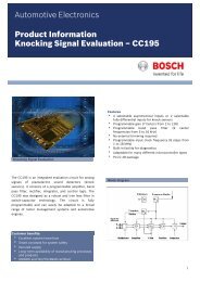
There are four different formats which differ in the length of the ARBITRATION FIELD <strong>and</strong><br />
in the CONTROL FIELD:<br />
<strong>CAN</strong> BASE FORMAT: 11 bit long identifier <strong>and</strong> constant bit rate<br />
<strong>CAN</strong> EXTENDED FORMAT: 29 bit long identifier <strong>and</strong> constant bit rate<br />
<strong>CAN</strong> <strong>FD</strong> BASE FORMAT: 11 bit long identifier <strong>and</strong> dual bit rate<br />
<strong>CAN</strong> <strong>FD</strong> EXTENDED FORMAT: 29 bit long identifier <strong>and</strong> dual bit rate<br />
3.2 FRAME TYPES<br />
Message transfer is manifested <strong>and</strong> controlled by four different frame types:<br />
ADATA FRAME carries data from a Transmitter to the Receivers. There are four subtypes<br />
of DATA FRAME in <strong>CAN</strong> <strong>FD</strong>:<br />
DATA FRAME in <strong>CAN</strong> BASE FORMAT<br />
DATA FRAME in <strong>CAN</strong> EXTENDED FORMAT<br />
DATA FRAME in <strong>CAN</strong> <strong>FD</strong> BASE FORMAT<br />
DATA FRAME in <strong>CAN</strong> <strong>FD</strong> EXTENDED FORMAT<br />
AREMOTE FRAME is transmitted by a bus unit to request the transmission of the DATA<br />
FRAME with the same IDENTIFIER format. A <strong>CAN</strong> <strong>FD</strong> mode shall support two subtypes of<br />
REMOTE FRAME:<br />
REMOTE FRAME in <strong>CAN</strong> BASE FORMAT<br />
REMOTE FRAME in <strong>CAN</strong> EXTENDED FORMAT<br />
There are no REMOTE FRAMES in <strong>CAN</strong> <strong>FD</strong> format.<br />
An ERROR FRAME is transmitted by any unit on detecting a bus error.<br />
An OVERLOAD FRAME is used to synchronize idle detection <strong>and</strong> to provide for an extra<br />
delay between the preceding <strong>and</strong> the succeeding DATA or REMOTE FRAMES.<br />
DATA FRAMES <strong>and</strong> REMOTE FRAMES are separated from preceding frames by an INTER-<br />
FRAME SPACE.<br />
3.2.1 DATA FRAME<br />
ADATA FRAME is composed of seven different bit fields:<br />
START OF FRAME, ARBITRATION FIELD, CONTROL FIELD, DATA FIELD, CRC FIELD, ACK<br />
FIELD, END OF FRAME. The DATA FIELD may be of length zero.<br />
© Copyright 2011, Robert <strong>Bosch</strong> GmbH, Robert <strong>Bosch</strong> Platz 1, 70839 Gerlingen, Germany
Message Transfer<br />
April 2012<br />
page 9<br />
INTERFRAME<br />
SPACE<br />
DATA FRAME<br />
INTERFRAME<br />
SPACE<br />
START OF FRAME<br />
ARBITRATION FIELD<br />
St<strong>and</strong>ard Bit Rate<br />
CONTROL FIELD<br />
optional High Bit Rate<br />
or<br />
OVERLOAD<br />
FRAME<br />
St<strong>and</strong>ard Bit Rate<br />
DATA FIELD<br />
CRC FIELD<br />
ACK FIELD<br />
END OF FRAME<br />
START OF FRAME<br />
The START OF FRAME (SOF) marks the beginning of DATA FRAMES <strong>and</strong> REMOTE FRAMES.<br />
It consists of a single dominant bit.<br />
A station is only allowed to start transmission when the bus is idle (see INTERFRAME<br />
SPACE). All stations have to synchronize to the leading edge caused by START OF FRAME<br />
(see HARD SYNCHRONIZATION) of the station starting transmission first.<br />
ARBITRATION FIELD<br />
The structure of the ARBITRATION FIELD is different for BASE FORMAT <strong>and</strong> EXTENDED FOR-<br />
MAT frames, but there is only one different bit in <strong>CAN</strong> format <strong>and</strong> <strong>CAN</strong> <strong>FD</strong> format.<br />
• In BASE FORMAT the ARBITRATION FIELD consists of the BASE IDENTIFIER <strong>and</strong> the RTR<br />
bit (<strong>CAN</strong> format) or the r1 bit (<strong>CAN</strong> <strong>FD</strong> format). The BASE IDENTIFIER is 11 bits long,<br />
denoted ID-28…ID-18.<br />
• In EXTENDED FORMAT the ARBITRATION FIELD consists of the EXTENDED IDENTIFIER,<br />
the SRR bit, the IDE bit, <strong>and</strong> the RTR bit (<strong>CAN</strong> format) or the r1 bit (<strong>CAN</strong> <strong>FD</strong> format).<br />
The EXTENDED IDENTIFIER consists of two sections, the first section is the BASE<br />
IDENTIFIER (denoted ID-28…ID-18), the second section is the IDENTIFIER EXTENSION<br />
(18 bits long, denoted ID-17…ID-0).<br />
© Copyright 2011, Robert <strong>Bosch</strong> GmbH, Robert <strong>Bosch</strong> Platz 1, 70839 Gerlingen, Germany
April 2012<br />
page 10<br />
Message Transfer<br />
<strong>CAN</strong> BASE FORMAT<br />
ARBITRATION FIELD<br />
CONTROL FIELD<br />
S<br />
O<br />
F<br />
BASE IDENTIFIER<br />
R<br />
T<br />
R<br />
I<br />
DE<br />
r<br />
0<br />
DLC<br />
<strong>CAN</strong> <strong>FD</strong> BASE FORMAT<br />
ARBITRATION FIELD<br />
CONTROL FIELD<br />
S<br />
O<br />
F<br />
BASE IDENTIFIER<br />
r<br />
1<br />
I E<br />
D D<br />
r<br />
E L<br />
0<br />
B E<br />
RS SI DLC<br />
DATA PHASE<br />
ARBITRATION PHASE<br />
<strong>CAN</strong> EXTENDED FORMAT<br />
ARBITRATION FIELD<br />
CONTROL FIELD<br />
S<br />
O<br />
F<br />
S<br />
R<br />
R<br />
I<br />
D<br />
E<br />
R<br />
TR<br />
r<br />
1<br />
r<br />
0<br />
BASE IDENTIFIER IDENTIFIER EXTENSION DLC<br />
<strong>CAN</strong> <strong>FD</strong> EXTENDED FORMAT<br />
ARBITRATION FIELD<br />
CONTROL FIELD<br />
S<br />
O<br />
F<br />
S<br />
R<br />
R<br />
I<br />
D<br />
r<br />
E<br />
r<br />
B E<br />
D<br />
E<br />
1 L 0 RS SI<br />
DATA PHASE<br />
BASE IDENTIFIER IDENTIFIER EXTENSION DLC<br />
ARBITRATION PHASE<br />
IDE<br />
The IDENTIFIER EXTENSION FLAG (IDE) belongs to<br />
• the ARBITRATION FIELD for the EXTENDED FORMAT<br />
• the CONTROL FIELD for the BASE FORMAT,<br />
it distinguishes between the formats. The IDE bit is transmitted dominant in the BASE<br />
FORMAT, whereas in the EXTENDED FORMAT the IDE bit is recessive.<br />
© Copyright 2011, Robert <strong>Bosch</strong> GmbH, Robert <strong>Bosch</strong> Platz 1, 70839 Gerlingen, Germany
Message Transfer<br />
April 2012<br />
page 11<br />
SRR<br />
The SUBSTITUTE REMOTE REQUEST (SRR) bit is recessive. It is transmitted in EXTENDED<br />
FORMAT at the position of the RTR bit in BASE FORMAT. Therefore, collisions of a frame<br />
in BASE FORMAT <strong>and</strong> a frame in EXTENDED FORMAT, the BASE IDENTIFIER of which is the<br />
same in both frames, are resolved in such a way that the frame in BASE FORMAT prevails<br />
the frame in EXTENDED FORMAT.<br />
RTR<br />
The REMOTE TRANSMISSION REQUEST (RTR) bit only exists in <strong>CAN</strong> format frames. It has<br />
to be dominant within DATA FRAMES <strong>and</strong> has to be recessive within REMOTE FRAMES. In<br />
<strong>CAN</strong> <strong>FD</strong> format frames, it is replaced with the dominant reserved bit r1. There are no<br />
REMOTE FRAMES in <strong>CAN</strong> <strong>FD</strong> format.<br />
CONTROL FIELD<br />
The structure of the CONTROL FIELD is different for <strong>CAN</strong> BASE FORMAT, <strong>CAN</strong> <strong>FD</strong> BASE<br />
FORMAT, <strong>and</strong> <strong>CAN</strong> EXTENDED FORMAT, <strong>and</strong> <strong>CAN</strong> <strong>FD</strong> EXTENDED FORMAT frames.<br />
• In <strong>CAN</strong> BASE FORMAT the CONTROL FIELD consists of the bits<br />
IDE, r0, <strong>and</strong> the<br />
4 bits wide DATA LENGTH CODE (DLC).<br />
• In <strong>CAN</strong> <strong>FD</strong> BASE FORMAT the CONTROL FIELD consists of the bits<br />
IDE, EDL,r0, BRS, ESI, <strong>and</strong> the 4 bits wide DATA LENGTH CODE (DLC).<br />
• In <strong>CAN</strong> EXTENDED FORMAT the CONTROL FIELD consists of the bits<br />
r1, r0, <strong>and</strong> the 4 bits wide DATA LENGTH CODE (DLC).<br />
• In <strong>CAN</strong> <strong>FD</strong> EXTENDED FORMAT the CONTROL FIELD consists of the bits<br />
EDL, r0, BRS, ESI, <strong>and</strong> the 4 bits wide DATA LENGTH CODE (DLC).<br />
EDL<br />
The EXTENDED DATA LENGTH (EDL) bit is recessive. It only exists in <strong>CAN</strong> <strong>FD</strong> format<br />
frames, it distinguishes between <strong>CAN</strong> format <strong>and</strong> <strong>CAN</strong> <strong>FD</strong> format frames. In a <strong>CAN</strong> format<br />
frame, the dominant bit r0 is transmitted instead of EDL. In frames with 11-bit identifiers,<br />
EDL comes after the IDE bit, in frames with 29-bit-identifier, it comes after the r1<br />
bit. EDL is always followed by the dominant bit r0, which is reserved for future expansion<br />
of the protocol.<br />
BRS<br />
The BIT RATE SWITCH (BRS) bit decides whether the bit rate is switched inside a<br />
<strong>CAN</strong> <strong>FD</strong> format frame. If the bit is transmitted recessive, the bit rate is switched from the<br />
st<strong>and</strong>ard bit rate of the ARBITRATION PHASE to the preconfigured alternate bit rate of the<br />
DATA PHASE. If it is transmitted dominant, the bit rate is not switched. BRS does not exist<br />
in <strong>CAN</strong> format frames.<br />
ESI<br />
The ERROR STATE INDICATOR (ESI) flag is transmitted dominant by error active nodes,<br />
recessive by error passive nodes. ESI does not exist in <strong>CAN</strong> format frames.<br />
The reserved bits r1 <strong>and</strong> r0 have to be sent dominant. Receivers accept dominant <strong>and</strong><br />
recessive bits in all combinations. Receivers also accept dominant SRR bits.<br />
© Copyright 2011, Robert <strong>Bosch</strong> GmbH, Robert <strong>Bosch</strong> Platz 1, 70839 Gerlingen, Germany
April 2012<br />
page 12<br />
Message Transfer<br />
DATA LENGTH CODE<br />
The number of bytes in the DATA FIELD is indicated by the DLC, its coding is different in<br />
<strong>CAN</strong> <strong>and</strong> in <strong>CAN</strong> <strong>FD</strong>. The first nine codes are the same, but the following codes, that in<br />
<strong>CAN</strong> all specify a DATA FIELD of eight bytes, specify longer DATA FIELDS in <strong>CAN</strong> <strong>FD</strong>.<br />
Coding of the number of data bytes by the DATA LENGTH CODE:<br />
Number of<br />
Data Bytes<br />
Data Length Code<br />
DLC3 DLC2 DLC1 DLC0<br />
0 0 0 0 0<br />
1 0 0 0 1<br />
2 0 0 1 0<br />
3 0 0 1 1<br />
4 0 1 0 0<br />
5 0 1 0 1<br />
6 0 1 1 0<br />
7 0 1 1 1<br />
<strong>CAN</strong> Format 8 1 0/1 0/1 0/1<br />
8 1 0 0 0<br />
12 1 0 0 1<br />
16 1 0 1 0<br />
20 1 0 1 1<br />
24 1 1 0 0<br />
32 1 1 0 1<br />
48 1 1 1 0<br />
Codes in <strong>CAN</strong> <strong>and</strong><br />
<strong>CAN</strong> <strong>FD</strong> Format<br />
Codes in<br />
<strong>CAN</strong> <strong>FD</strong> Format<br />
64 1 1 1 1<br />
DATA FIELD<br />
The DATA FIELD consists of the data to be transferred within a DATA FRAME. It can contain<br />
from 0 to 8 bytes in <strong>CAN</strong> Format <strong>and</strong> 0 to 64 bytes in <strong>CAN</strong> <strong>FD</strong> format. The bytes<br />
each contain 8 bits which are transferred MSB first. When the DLC is zero, or in<br />
REMOTE FRAMES, there is no DATA FIELD.<br />
CRC FIELD<br />
The CRC FIELD contains the CRC SEQUENCE followed by the recessive CRC DELIMITER<br />
bit.<br />
© Copyright 2011, Robert <strong>Bosch</strong> GmbH, Robert <strong>Bosch</strong> Platz 1, 70839 Gerlingen, Germany
Message Transfer<br />
April 2012<br />
page 13<br />
DATA or<br />
CONTROL FIELD<br />
CRC FIELD<br />
ACK FIELD<br />
CRC SEQUENCE<br />
CRC<br />
DELIM<br />
ITER<br />
ACK<br />
SLOT<br />
ACK<br />
DELIM<br />
ITER<br />
DATA PHASE<br />
ARBITRATION PHASE<br />
CRC SEQUENCE<br />
The frame check sequence is derived from a cyclic redundancy code (BCH Code).<br />
A <strong>CAN</strong> <strong>FD</strong> node uses different CRC generator-polynomials for different frame formats.<br />
The first polynomial, CRC_15, is used for all frames in <strong>CAN</strong> format. The second,<br />
CRC_17, is used for frames in <strong>CAN</strong> <strong>FD</strong> format with a DATA FIELD up to sixteen byte<br />
long. The third, CRC_21, is used for frames in <strong>CAN</strong> <strong>FD</strong> format with a DATA FIELD longer<br />
than sixteen byte. Each polynomial results in a Hamming Distance of HD = 6.<br />
• CRC_15 0xC599 (x 15 +x 14 +x 10 +x 8 +x 7 +x 4 +x 3 +1)<br />
= (x+1) · (x 7 +x 3 +1) · (x 7 +x 3 +x 2 +x+1)<br />
• CRC_17 0x3685B (x 17 +x 16 +x 14 +x 13 +x 11 +x 6 +x 4 +x 3 +x 1 +1)<br />
= (x+1) · (x 16 +x 13 +x 10 +x 9 +x 8 +x 7 +x 6 +x 3 +1)<br />
• CRC_21 0x302899 (x 21 +x 20 +x 13 +x 11 +x 7 +x 4 +x 3 +1)<br />
= (x+1) · (x 10 +x 3 +1) · (x 10 +x 3 +x 2 +x 1 +1)<br />
The length of the CRC SEQUENCE (n CRC , the order of the generator-polynomial) is set to<br />
15 for CRC_15, to 17 for CRC_17, <strong>and</strong> to 21 for CRC_21.<br />
At the start of the frame, all three CRC SEQUENCES shall be calculated concurrently; in<br />
all nodes including the Transmitter. The node that wins the arbitration sends the CRC<br />
SEQUENCE selected by the values of the frame’s EDL bit <strong>and</strong> DLC. The Receivers shall<br />
consider only the selected CRC polynomial to check for a CRC-ERROR.<br />
The relevant bit stream for CRC calculation is the bit stream consisting of START OF<br />
FRAME, ARBITRATION FIELD, CONTROL FIELD, <strong>and</strong> (if present) DATA FIELD, supplemented<br />
with n CRC bits of ’0’. In <strong>CAN</strong> <strong>FD</strong> format frames, STUFF-BITS are included in the relevant<br />
bit stream for CRC calculation, in <strong>CAN</strong> format frames, STUFF-BITS are not included.<br />
In order to carry out the CRC calculation, the polynomial to be divided is defined by the<br />
coefficients of the relevant bit stream. This polynomial is divided (the coefficients are<br />
calculated modulo-2) by the generator-polynomial.<br />
The remainder of this polynomial division is the CRC SEQUENCE transmitted over the<br />
bus. In order to implement this function, a n CRC bit shift register CRC_RG(n CRC -1:0)<br />
can be used. Each CRC SEQUENCE is calculated in a separate shift register block. If<br />
NXTBIT denotes the next bit of the bit stream, given by the relevant bit stream from<br />
© Copyright 2011, Robert <strong>Bosch</strong> GmbH, Robert <strong>Bosch</strong> Platz 1, 70839 Gerlingen, Germany
April 2012<br />
page 14<br />
Message Transfer<br />
START OF FRAME until the end of the DATA FIELD, the CRC SEQUENCES are calculated as<br />
follows:<br />
CRC_RG = 0;<br />
// initialize shift register<br />
REPEAT<br />
CRCNXT = NXTBIT EXOR CRC_RG(n CRC -1);<br />
CRC_RG(n CRC -1:1) = CRC_RG(n CRC -2:0); // shift left by 1 position<br />
CRC_RG(0) = 0;<br />
IF CRCNXT THEN<br />
CRC_RG(n CRC -1:0) = CRC_RG(n CRC -1:0) EXOR (CRC polynomial);<br />
ENDIF<br />
UNTIL (CRC SEQUENCE starts or there is an ERROR condition)<br />
After the transmission / reception of the last bit of the relevant bit stream, each<br />
CRC_RG contains one of the three CRC SEQUENCES.<br />
CRC DELIMITER<br />
The CRC SEQUENCE is followed by the CRC DELIMITER. In <strong>CAN</strong> format, the CRC DELIM-<br />
ITER is one single recessive bit. In <strong>CAN</strong> <strong>FD</strong> format, the CRC DELIMITER may consist of<br />
one or two recessive bits. A Transmitter shall send only one recessive bit as CRC DELIM-<br />
ITER, but it shall accept two recessive bits before the edge from recessive to dominant that<br />
starts the ACKNOWLEDGE SLOT. AReceiver will send its ACKNOWLEDGE bit after the first<br />
CRC DELIMITER bit.<br />
Note: <strong>CAN</strong> <strong>FD</strong> protocol controllers switch back from the DATA-PHASE to the ARBITRA-<br />
TION PHASE when they reach the SAMPLE POINT of the (first bit of the) CRC DELIMITER.<br />
CRC FIELD<br />
ACK FIELD<br />
END OF FRAME<br />
CRC<br />
SEQUENCE<br />
CRC<br />
DELIMITER<br />
ACK<br />
SLOT<br />
ACK<br />
DELIMITER<br />
DATA PHASE<br />
ARBITRATION PHASE<br />
ACK FIELD<br />
The ACK FIELD contains the ACK SLOT <strong>and</strong> the ACK DELIMITER. In the ACK FIELD, the<br />
transmitting station sends recessive bits.<br />
The phase-shift between the nodes in a <strong>CAN</strong> network is defined by the delay times in<br />
the transceivers <strong>and</strong> the propagation time on the <strong>CAN</strong> bus line. The phase-shift is the<br />
same in <strong>CAN</strong> <strong>and</strong> in <strong>CAN</strong> <strong>FD</strong>, but it is proportionally larger in the phase with the shorter<br />
bit time. All Receivers in the network may have a different phase-shift to the Transmitter,<br />
depending on their distances from the Transmitter, since they see the transmitted edges<br />
at different times. To compensate for these phase-shifts when the bit rate is switched<br />
back from the shorter to the longer bit time, one additional bit time tolerance is allowed<br />
before <strong>and</strong> after the edge from recessive to dominant that starts the ACKNOWLEDGE SLOT.<br />
© Copyright 2011, Robert <strong>Bosch</strong> GmbH, Robert <strong>Bosch</strong> Platz 1, 70839 Gerlingen, Germany
Message Transfer<br />
April 2012<br />
page 15<br />
A Receiver which has received a valid message correctly, reports this to the Transmitter<br />
by sending one dominant bit at the start of the ACK SLOT.<br />
ACK SLOT<br />
All stations having received the matching CRC SEQUENCE report this within the ACK<br />
SLOT by superscribing the recessive bit of the Transmitter with one dominant bit (they send<br />
ACK). In <strong>CAN</strong> <strong>FD</strong> format, all nodes shall accept a two bit long dominant phase of overlapping<br />
ACK bits as a valid ACK, to compensate for phase shifts between the Receivers. In<br />
<strong>CAN</strong> format, a dominant bit following the single ACK SLOT bit is a FORM-ERROR.<br />
ACK DELIMITER<br />
The recessive ACK DELIMITER is the last bit of the ACK FIELD. As a consequence, the ACK<br />
SLOT is surrounded by two recessive bits (CRC DELIMITER, ACK DELIMITER).<br />
END OF FRAME<br />
Each DATA FRAME <strong>and</strong> REMOTE FRAME is delimited by a flag sequence consisting of<br />
seven recessive bits.<br />
3.2.2 REMOTE FRAME<br />
A station acting as a Receiver for certain data can initiate the transmission of the respective<br />
data by its source node by sending a REMOTE FRAME.<br />
AREMOTE FRAME is composed of six different bit fields:<br />
START OF FRAME, ARBITRATION FIELD, CONTROL FIELD, CRC FIELD, ACK FIELD, END OF<br />
FRAME.<br />
Contrary to DATA FRAMES, the RTR bit of REMOTE FRAMES is recessive. There is no DATA<br />
FIELD, independent of the values of the DATA LENGTH CODE which may be signed any<br />
value within the admissible range 0…15. The value shall be the DATA LENGTH CODE of<br />
the corresponding DATA FRAME. The REMOTE FRAME is only defined in the <strong>CAN</strong> format,<br />
neither REMOTE FRAME nor RTR bit exist in the <strong>CAN</strong> <strong>FD</strong> format.<br />
INTERFRAME<br />
SPACE<br />
START OF FRAME<br />
ARBITRATION FIELD<br />
CONTROL FIELD<br />
REMOTE FRAME<br />
CRC FIELD<br />
ACK FIELD<br />
END OF FRAME<br />
INTERFRAME<br />
SPACE<br />
or<br />
OVERLOAD<br />
FRAME<br />
© Copyright 2011, Robert <strong>Bosch</strong> GmbH, Robert <strong>Bosch</strong> Platz 1, 70839 Gerlingen, Germany
April 2012<br />
page 16<br />
Message Transfer<br />
3.2.3 ERROR FRAME<br />
The ERROR FRAME consists of two different fields. The first field is given by the superposition<br />
of ERROR FLAGS contributed from different stations. The following second field is<br />
the ERROR DELIMITER.<br />
DATA<br />
FRAME<br />
ERROR FLAG<br />
ERROR FRAME<br />
INTERFRAME<br />
SPACE or<br />
OVERLOAD<br />
FRAME<br />
superposition of<br />
ERROR FLAGS<br />
ERROR DELIMITER<br />
In order to terminate an ERROR FRAME correctly, an error passive node may need the bus<br />
to be BUS IDLE for at least 3 bit times (if there is a local error at an error passive Receiver).<br />
Therefore the bus should not be loaded to 100%.<br />
ERROR FLAG<br />
There are two forms of an ERROR FLAG: anACTIVE ERROR FLAG <strong>and</strong> a PASSIVE ERROR<br />
FLAG.<br />
1. The ACTIVE ERROR FLAG consists of six consecutive dominant bits.<br />
2. The PASSIVE ERROR FLAG consists of six consecutive recessive bits unless it is<br />
overwritten by dominant bits from other nodes.<br />
An error active station detecting an error condition signals this by transmission of an<br />
ACTIVE ERROR FLAG. The ERROR FLAG’S form violates the law of bit stuffing (see section<br />
5: Coding) applied to all fields from START OF FRAME to CRC DELIMITER or destroys the<br />
fixed form ACK FIELD or END OF FRAME FIELD. As a consequence, all other stations<br />
detect an error condition <strong>and</strong> on their part start transmission of an ERROR FLAG. Sothe<br />
sequence of dominant bits which actually can be monitored on the bus results from a<br />
superposition of different ERROR FLAGS transmitted by individual stations. The total<br />
length of this sequence varies between a minimum of six <strong>and</strong> a maximum of twelve bits.<br />
An error passive station detecting an error condition tries to signal this by transmission of<br />
aPASSIVE ERROR FLAG. The error passive station waits for six consecutive bits of equal<br />
polarity, beginning at the start of the PASSIVE ERROR FLAG. The PASSIVE ERROR FLAG is<br />
complete when these 6 equal bits have been detected.<br />
ERROR DELIMITER<br />
The ERROR DELIMITER consists of eight recessive bits.<br />
After transmission of an ERROR FLAG each station sends recessive bits <strong>and</strong> monitors the<br />
bus until it detects a recessive bit. Afterwards it starts transmitting seven more recessive<br />
bits.<br />
© Copyright 2011, Robert <strong>Bosch</strong> GmbH, Robert <strong>Bosch</strong> Platz 1, 70839 Gerlingen, Germany
Message Transfer<br />
April 2012<br />
page 17<br />
3.2.4 OVERLOAD FRAME<br />
The OVERLOAD FRAME contains the two bit fields OVERLOAD FLAG <strong>and</strong> OVERLOAD DELIM-<br />
ITER.<br />
There are three kinds of OVERLOAD conditions, which lead to the transmission of an<br />
OVERLOAD FLAG:<br />
1. The internal conditions of a Receiver, which requires a delay of the next DATA FRAME<br />
or REMOTE FRAME.<br />
2. Detection of a dominant bit at the first or second bit of INTERMISSION.<br />
3. If a <strong>CAN</strong> <strong>FD</strong> node samples a dominant bit at the eighth bit (the last bit) of an ERROR<br />
DELIMITER or OVERLOAD DELIMITER, or if a <strong>CAN</strong> <strong>FD</strong> Receiver samples a dominant bit<br />
at the last bit of END OF FRAME, it will start transmitting an OVERLOAD FRAME (not an<br />
ERROR FRAME). The Error Counters will not be incremented.<br />
The start of an OVERLOAD FRAME due to OVERLOAD condition 1 is only allowed to be<br />
started at the first bit time of an expected INTERMISSION, whereas OVERLOAD FRAMES<br />
due to OVERLOAD condition 2 or condition 3 start one bit after detecting the dominant bit.<br />
END OF FRAME OR<br />
ERROR DELIMITER OR<br />
OVERLOAD DELIMITER<br />
OVERLOAD<br />
FLAG<br />
OVERLOAD FRAME<br />
INTERFRAME<br />
SPACE<br />
OVERLOAD<br />
FRAME<br />
or<br />
SUPERPOSITION OF<br />
OVERLOAD FLAGS<br />
OVERLOAD DELIMITER<br />
At most two OVERLOAD FRAMES may be generated to delay the next DATA or REMOTE<br />
FRAME.<br />
OVERLOAD FLAG<br />
consists of six dominant bits. The overall form corresponds to that of the ACTIVE ERROR<br />
FLAG.<br />
The OVERLOAD FLAG’S form destroys the fixed form of the INTERMISSION FIELD. As a consequence,<br />
all other stations also detect an OVERLOAD condition <strong>and</strong> on their part start<br />
transmission of an OVERLOAD FLAG. (In case that there is a dominant bit detected during<br />
the 3rd bit of INTERMISSION locally at some node, the other nodes will not interpret the<br />
OVERLOAD FLAG correctly, but interpret the first of these six dominant bits as START OF<br />
FRAME. The sixth dominant bit violates the rule of bit stuffing causing an error condition).<br />
OVERLOAD DELIMITER<br />
consists of eight recessive bits.<br />
The OVERLOAD DELIMITER is of the same form as the ERROR DELIMITER. After transmission<br />
of an OVERLOAD FLAG the station monitors the bus until it detects a transition from a<br />
© Copyright 2011, Robert <strong>Bosch</strong> GmbH, Robert <strong>Bosch</strong> Platz 1, 70839 Gerlingen, Germany
April 2012<br />
page 18<br />
Message Transfer<br />
dominant to a recessive bit. At this point of time every bus station has finished sending its<br />
OVERLOAD FLAG <strong>and</strong> all stations start transmission of seven more recessive bits in coincidence.<br />
3.2.5 INTERFRAME SPACE<br />
DATA FRAMES <strong>and</strong> REMOTE FRAMES are separated from preceding frames whatever type<br />
they are (DATA FRAME, REMOTE FRAME, ERROR FRAME, OVERLOAD FRAME) by a bit field<br />
called INTERFRAME SPACE. In contrast, OVERLOAD FRAMES <strong>and</strong> ERROR FRAMES are not<br />
preceded by an INTERFRAME SPACE <strong>and</strong> multiple OVERLOAD FRAMES are not separated<br />
by an INTERFRAME SPACE.<br />
INTERFRAME SPACE contains the bit fields INTERMISSION <strong>and</strong> BUS IDLE <strong>and</strong>, for error passive<br />
stations, which have been Transmitter of the previous message, SUSPEND TRANSMIS-<br />
SION.<br />
For stations which are not error passive or have been Receiver of the previous message:<br />
FRAME<br />
INTERFRAME SPACE<br />
FRAME<br />
INTERMISSION<br />
BUS IDLE<br />
For error passive stations which have been Transmitter of the previous message:<br />
FRAME<br />
INTERFRAME SPACE<br />
FRAME<br />
INTERMISSION<br />
BUS IDLE<br />
SUSPEND TRANSMISSION<br />
INTERMISSION<br />
consists of three recessive bits.<br />
During INTERMISSION no station is allowed to start transmission of a DATA FRAME or<br />
REMOTE FRAME. The only action to be taken is signalling an OVERLOAD condition.<br />
The detection of a dominant bit on the bus at the third bit of INTERMISSION shall be interpreted<br />
as START OF FRAME.<br />
© Copyright 2011, Robert <strong>Bosch</strong> GmbH, Robert <strong>Bosch</strong> Platz 1, 70839 Gerlingen, Germany
Message Transfer<br />
April 2012<br />
page 19<br />
Note: A <strong>CAN</strong> <strong>FD</strong> node with a pending transmission that is error active or has been<br />
Receiver of the previous frame shall, if it samples a dominant bit at the third bit of INTER-<br />
MISSION, start transmitting its message with the first bit of its BASE IDENTIFIER at the next<br />
bit, without first transmitting a START OF FRAME bit <strong>and</strong> without becoming Receiver.<br />
BUS IDLE<br />
The period of BUS IDLE may be of arbitrary length. The bus is recognized to be free <strong>and</strong><br />
any station having something to transmit can access the bus. A message which is pending<br />
for transmission during the transmission of another message is started in the first bit<br />
following INTERMISSION.<br />
The detection of a dominant bit on the bus is interpreted as a START OF FRAME.<br />
SUSPEND TRANSMISSION<br />
After an error passive station has transmitted a message, it sends eight recessive bits following<br />
INTERMISSION, before starting to transmit a further message or recognizing the<br />
bus to be BUS IDLE. If meanwhile a transmission (caused by another station) starts, the<br />
station will become Receiver of this message.<br />
3.2.6 DATA CONSISTENCY<br />
Messages to be transmitted are prepared by the host <strong>and</strong> are transferred via the node’s<br />
controller-host interface <strong>and</strong> LLC sublayer of the Data Link Layer to the MAC sublayer<br />
that is responsible for Message Framing. Messages may be stored in a shared memory<br />
Data consistency of transmitted messages from a shared memory shall be ensured by<br />
at least one of two methods:<br />
• The MAC sublayer shall store the whole message to be transmitted in a temporary<br />
buffer that is filled before the transmission is started.<br />
• The LLC sublayer shall check for data errors while the message to be transmitted is<br />
transferred to the MAC sublayer. If a data error is detected, the transmission shall<br />
not be started. If it is already started when the data error is detected, the node shall<br />
be switched into Bus Monitoring Mode, see section 3.3.1. Receiving nodes will not<br />
see a valid message.<br />
Note: Data errors are e.g. parity errors in a RAM word, data not provided in time, or<br />
data partially updated during a transmission.<br />
3.3 OPERATION MODES<br />
A <strong>CAN</strong> <strong>FD</strong> unit is in one of four operation state , Integrating, Idle, Receiver, orTransmitter.<br />
They are defined as follows:<br />
Integrating<br />
A unit is Integrating while it waits to detect eleven consecutive recessive bits after the<br />
start of the controller or during bus_off recovery, then switching to Idle.<br />
© Copyright 2011, Robert <strong>Bosch</strong> GmbH, Robert <strong>Bosch</strong> Platz 1, 70839 Gerlingen, Germany
April 2012<br />
page 20<br />
Message Transfer<br />
Idle<br />
A unit is Idle if it is ready for a START OF FRAME, switching to either Receiver or Transmitter.<br />
Receiver<br />
A unit operates as Receiver if it detects activity on the <strong>CAN</strong> bus <strong>and</strong> if it is not Transmitter.<br />
Transmitter<br />
A unit originating a message is operating as Transmitter. The unit stays Transmitter until<br />
the bus is idle or the unit loses ARBITRATION.<br />
3.3.1 BUS MONITORING MODE<br />
In an optional Bus Monitoring Mode, the <strong>CAN</strong> <strong>FD</strong> node shall be able to receive valid<br />
DATA FRAMES <strong>and</strong> valid REMOTE FRAMES, but it sends only recessive bits on the <strong>CAN</strong> bus<br />
<strong>and</strong> cannot start a transmission. If the <strong>CAN</strong> <strong>FD</strong> protocol controller is required to send a<br />
dominant bit (ACK SLOT, OVERLOAD FLAG, ACTIVE ERROR FLAG), the bit is rerouted internally<br />
so that the <strong>CAN</strong> <strong>FD</strong> protocol controller monitors this dominant bit, although the<br />
<strong>CAN</strong> bus may remain in recessive state.<br />
3.3.2 RESTRICTED OPERATION MODE<br />
In an optional Restricted Operation Mode, a <strong>CAN</strong> <strong>FD</strong> node is able to transmit <strong>and</strong> to<br />
receive DATA FRAMES <strong>and</strong> REMOTE FRAMES <strong>and</strong> it gives ACKNOWLEDGE to valid frames,<br />
but it does not send ACTIVE ERROR FRAMES or OVERLOAD FRAMES. In case of an error<br />
condition or overload condition, it does not send dominant bits, instead it waits for the<br />
occurrence of BUS IDLE condition to resynchronize itself to the <strong>CAN</strong> communication. The<br />
error counters are not incremented.<br />
© Copyright 2011, Robert <strong>Bosch</strong> GmbH, Robert <strong>Bosch</strong> Platz 1, 70839 Gerlingen, Germany
Message Validation<br />
April 2012<br />
page 21<br />
4 MESSAGE VALIDATION<br />
The point of time at which a message is taken to be valid, is different for the Transmitter<br />
<strong>and</strong> the Receivers of the message.<br />
Transmitter:<br />
The message is valid for the Transmitter, if there is no error until the end of END OF<br />
FRAME. If a message is corrupted, retransmission will follow automatically <strong>and</strong> according<br />
to prioritization. In order to be able to compete for bus access with other messages,<br />
retransmission has to start as soon as the bus is idle. The number of retransmission<br />
attempts may be limited (by configuration) to a specific value. By default, the number of<br />
retransmissions is not limited<br />
Receivers:<br />
The message is valid for the Receivers, if there is no error until the last but one bit of END<br />
OF FRAME. The value of the last bit of END OF FRAME is treated as ’don’t care’, a dominant<br />
value does not lead to a FORM-ERROR see section 6.1: Error Detection). A Receiver<br />
that detects a dominant bit at the last bit of END OF FRAME responds with an OVERLOAD<br />
FRAME.<br />
4.1 MESSAGE FILTERING<br />
Message filtering is based upon the whole Identifier, it decides whether a received message<br />
is discarded or is stored inside the node. Optional mask registers that allow any<br />
IDENTIFIER bit to be set ’don’t care’ for message filtering may be used to select groups of<br />
IDENTIFIERS to be mapped into the attached receive buffers.<br />
If mask registers are implemented every bit of the mask registers must be programmable,<br />
i.e. they can be enabled or disabled for message filtering. The length of the mask<br />
register can comprise the whole IDENTIFIER or only part of it.<br />
© Copyright 2011, Robert <strong>Bosch</strong> GmbH, Robert <strong>Bosch</strong> Platz 1, 70839 Gerlingen, Germany
April 2012<br />
page 22<br />
Coding<br />
5 CODING<br />
BIT STREAM CODING<br />
The bit stream in a message is coded according to the Non-Return-to-Zero (NRZ)<br />
method. This means that during the total bit time the generated bit level is either dominant<br />
or recessive.<br />
In order to limit the maximum distance between edges available for synchronization, the<br />
frame segments START OF FRAME, ARBITRATION FIELD, CONTROL FIELD, DATA FIELD <strong>and</strong><br />
CRC SEQUENCE are coded by the method of bit stuffing. Whenever a Transmitter detects<br />
five consecutive bits of identical value in the bit stream to be transmitted, it automatically<br />
inserts a complementary bit (called STUFF-BIT) into the actual transmitted bit<br />
stream.The Receiver shall recognize a sequence of five consecutive bits of identical<br />
value <strong>and</strong> discard the following STUFF-BIT.<br />
The remaining bit fields of the DATA FRAME or REMOTE FRAME (CRC DELIMITER, ACK<br />
FIELD, <strong>and</strong> END OF FRAME) are of fixed form <strong>and</strong> not stuffed. The ERROR FRAME <strong>and</strong> the<br />
OVERLOAD FRAME are of fixed form as well <strong>and</strong> not coded by the method of bit stuffing.<br />
In <strong>CAN</strong> <strong>FD</strong> format frames, the <strong>CAN</strong> bit stuffing method is changed for the CRC<br />
SEQUENCE. Here, the STUFF-BITS shall be inserted at fixed positions. There shall be a<br />
fixed STUFF-BIT before the first bit of the CRC SEQUENCE, even if the last bits of the preceding<br />
field do not fulfill the <strong>CAN</strong> stuff condition. A further STUFF-BIT shall be inserted<br />
after each fourth bit of the CRC SEQUENCE. The value of such a fixed STUFF-BIT shall be<br />
the inverse value of the bit preceding the fixed STUFF-BIT. AReceiver shall discard the<br />
fixed STUFF-BITS from the bit stream for the CRC check, it shall detect a STUFF-ERROR if<br />
the fixed STUFF-BIT has the same value as its preceding bit. The number of fixed STUFF-<br />
BITS in the <strong>CAN</strong> <strong>FD</strong> format CRC SEQUENCE is equal to the maximum number of stuff bits<br />
that would result from applying the <strong>CAN</strong> Format stuffing method. The fixed STUFF-BITS<br />
in the CRC SEQUENCE shall be discarded by the Receivers.<br />
© Copyright 2011, Robert <strong>Bosch</strong> GmbH, Robert <strong>Bosch</strong> Platz 1, 70839 Gerlingen, Germany
Error H<strong>and</strong>ling<br />
April 2012<br />
page 23<br />
6 ERROR HANDLING<br />
6.1 ERROR DETECTION<br />
There are 5 different error types (which are not mutually exclusive):<br />
BIT-ERROR<br />
A unit that is sending a bit on the bus also monitors the bus. A BIT-ERROR has to be<br />
detected at that bit time, when the bit value that is monitored is different from the bit<br />
value that is sent. An exception is the sending of a recessive bit during the stuffed bit<br />
stream of the ARBITRATION FIELD or during the ACK SLOT. Then no BIT-ERROR occurs<br />
when a dominant bit is monitored. A Transmitter sending a PASSIVE ERROR FLAG <strong>and</strong><br />
detecting a dominant bit does not interpret this as a BIT-ERROR.<br />
STUFF-ERROR<br />
ASTUFF-ERROR shall be detected at the bit time of the 6th consecutive equal bit level in<br />
a message field that should be coded by the method of bit stuffing.<br />
CRC-ERROR<br />
The CRC SEQUENCE consists of the result of the CRC calculation by the Transmitter. The<br />
Receivers calculate the CRC in the same way as the Transmitter. A CRC-ERROR shall be<br />
detected if the calculated result is not the same as that received in the CRC SEQUENCE.<br />
FORM-ERROR<br />
AFORM-ERROR shall be detected when a fixed-form bit field contains one or more illegal<br />
bits. (Exception is the detection of a dominant bit during the last bit of END OF FRAME<br />
byaRECEIVER, or the detection of a dominant bit during the last bit of ERROR DELIMITER<br />
or OVERLOAD DELIMITER by any node). When the value of a fixed STUFF-BIT in the<br />
<strong>CAN</strong> <strong>FD</strong> format CRC SEQUENCE is equal to its preceding bit, this shall also be detected<br />
as a FORM-ERROR.<br />
ACKNOWLEDGMENT-ERROR<br />
An ACKNOWLEDGMENT-ERROR has to be detected by a Transmitter whenever it does not<br />
monitor a dominant bit during the ACK SLOT.<br />
6.2 ERROR SIGNALLING<br />
A station detecting an error condition signals this by transmitting an ERROR FLAG. For an<br />
error active node it is an ACTIVE ERROR FLAG, for an error passive node it is a PASSIVE<br />
ERROR FLAG. Whenever a BIT-ERROR, aSTUFF-ERROR, aFORM-ERROR or an ACKNOWL-<br />
EDGMENT-ERROR is detected by any station, transmission of an ERROR FLAG is started at<br />
the respective station at the next bit.<br />
Whenever a CRC-ERROR is detected, transmission of an ERROR FLAG starts at the bit<br />
following the ACK DELIMITER, unless an ERROR FLAG for another condition has already<br />
been started.<br />
A <strong>CAN</strong> <strong>FD</strong> node operating in the DATA-PHASE shall switch back to the ARBITRATION-<br />
PHASE when starting an ERROR FLAG.<br />
© Copyright 2011, Robert <strong>Bosch</strong> GmbH, Robert <strong>Bosch</strong> Platz 1, 70839 Gerlingen, Germany
April 2012<br />
page 24<br />
Fault Confinement<br />
7 FAULT CONFINEMENT<br />
With respect to fault confinement a unit may be in one of three states:<br />
• error active<br />
• error passive<br />
• bus_off<br />
An error active unit can normally take part in bus communication <strong>and</strong> sends an ACTIVE<br />
ERROR FLAG when an error has been detected.<br />
An error passive unit must not send an ACTIVE ERROR FLAG. It takes part in bus communication,<br />
but when an error has been detected only a PASSIVE ERROR FLAG is sent. Also<br />
after a transmission, an error passive unit will wait before initiating a further transmission.<br />
(See SUSPEND TRANSMISSION)<br />
A bus_off unit is not allowed to have any influence on the bus. (E.g. output drivers<br />
switched off.)<br />
For fault confinement two counts are implemented in every bus unit:<br />
1) TRANSMIT ERROR COUNT<br />
2) RECEIVE ERROR COUNT<br />
These counts are modified according to the following rules:<br />
(note that more than one rule may apply during a given message transfer)<br />
1. When a RECEIVER detects an error, the RECEIVE ERROR COUNT will be increased by<br />
1, except when the detected error was a BIT-ERROR during the sending of an ACTIVE<br />
ERROR FLAG or an OVERLOAD FLAG.<br />
2. When a RECEIVER detects a dominant bit as the first bit after sending an ERROR FLAG<br />
the RECEIVE ERROR COUNT will be increased by 8.<br />
3. When a Transmitter sends an ERROR FLAG the TRANSMIT ERROR COUNT is increased<br />
by 8.<br />
Exception 1:<br />
If the Transmitter is error passive <strong>and</strong> detects an ACKNOWLEDGMENT-ERROR because<br />
of not detecting a dominant ACK <strong>and</strong> does not detect a dominant bit while sending its<br />
PASSIVE ERROR FLAG.<br />
Exception 2:<br />
If the Transmitter sends an ERROR FLAG because a STUFF-ERROR occurred during<br />
ARBITRATION, <strong>and</strong> should have been recessive, <strong>and</strong> has been sent as recessive but<br />
monitored as dominant.<br />
In exceptions 1 <strong>and</strong> 2 the TRANSMIT ERROR COUNT is not changed.<br />
4. If an Transmitter detects a BIT-ERROR while sending an ACTIVE ERROR FLAG or an<br />
OVERLOAD FLAG the TRANSMIT ERROR COUNT is increased by 8.<br />
5. If an RECEIVER detects a BIT-ERROR while sending an ACTIVE ERROR FLAG or an<br />
OVERLOAD FLAG the RECEIVE ERROR COUNT is increased by 8.<br />
© Copyright 2011, Robert <strong>Bosch</strong> GmbH, Robert <strong>Bosch</strong> Platz 1, 70839 Gerlingen, Germany
Fault Confinement<br />
April 2012<br />
page 25<br />
6. Any node tolerates up to 7 consecutive dominant bits after sending an ACTIVE ERROR<br />
FLAG, PASSIVE ERROR FLAG or OVERLOAD FLAG. After detecting the 14th consecutive<br />
dominant bit (in case of an ACTIVE ERROR FLAG or an OVERLOAD FLAG) or after<br />
detecting the 8th consecutive dominant bit following a PASSIVE ERROR FLAG, <strong>and</strong> after<br />
each sequence of additional eight consecutive dominant bits every Transmitter<br />
increases its TRANSMIT ERROR COUNT by 8 <strong>and</strong> every RECEIVER increases its<br />
RECEIVE ERROR COUNT by 8.<br />
7. After the successful transmission of a message (getting ACK <strong>and</strong> no error until END<br />
OF FRAME is finished) the TRANSMIT ERROR COUNT is decreased by 1 unless it was<br />
already 0.<br />
8. After the successful reception of a message (reception without error up to the ACK<br />
SLOT <strong>and</strong> the successful sending of the ACK bit), the RECEIVE ERROR COUNT is<br />
decreased by 1, if it was between 1 <strong>and</strong> 127. If the RECEIVE ERROR COUNT was 0, it<br />
stays 0, <strong>and</strong> if it was greater than 127, then it will be set to a value between 119 <strong>and</strong><br />
127.<br />
9. A node is error passive when the TRANSMIT ERROR COUNT equals or exceeds 128, or<br />
when the RECEIVE ERROR COUNT equals or exceeds 128. An error condition letting a<br />
node become error passive causes the node to send an ACTIVE ERROR FLAG.<br />
10.A node is bus_off when the TRANSMIT ERROR COUNT is greater than or equal to 256.<br />
11.An error passive node becomes error active again when both the TRANSMIT ERROR<br />
COUNT <strong>and</strong> the RECEIVE ERROR COUNT are less than or equal to 127.<br />
12.An node which is bus_off is permitted to become error active (no longer bus_off) with<br />
its error counters both set to 0 after 128 occurrence of 11 consecutive recessive bits<br />
have been monitored on the bus.<br />
Note: An error count value greater than about 96 indicates a heavily disturbed bus. It<br />
may be of advantage to provide means to test for this condition.<br />
Note: Start-up / Wake-up:<br />
If during start-up only 1 node is online, <strong>and</strong> if this node transmits some message, it will<br />
get no ACKNOWLEDGE, detect an error <strong>and</strong> repeat the message. It can become error passive<br />
but not bus_off due to this reason.<br />
© Copyright 2011, Robert <strong>Bosch</strong> GmbH, Robert <strong>Bosch</strong> Platz 1, 70839 Gerlingen, Germany
April 2012<br />
page 26<br />
Bit Timing Requirements<br />
8 BIT TIMING REQUIREMENTS<br />
The <strong>CAN</strong> <strong>FD</strong> protocol defines two bit rates, the first for the ARBITRATION-PHASE with a<br />
longer bit time <strong>and</strong> the second for the data phase with the same or with a shorter bit<br />
time. The definition for the first bit rate is the same as for the NOMINAL BIT RATE <strong>and</strong> the<br />
NOMINAL BIT TIME in the <strong>CAN</strong> protocol specification. The definition for the second bit<br />
rate, the DATA BIT RATE WITH the DATA BIT TIME, requires a separate configuration register<br />
set. Both bit times consist of separate non-overlapping time segments, these segments<br />
form the bit time as shown in this figure:<br />
NOMINAL OR DATA BIT TIME<br />
SYNC_SEG PROP_SEG PHASE_SEG1 PHASE_SEG2<br />
SAMPLE POINT<br />
SYNCHRONIZATION SEGMENT (SYNC_SEG)<br />
This part of the bit time is used to synchronize the various nodes on the bus. An edge is<br />
expected to lie within this segment.<br />
PROPAGATION TIME SEGMENT (PROP_SEG)<br />
This part of the bit time is used to compensate for the physical delay times within the<br />
network. It is twice the sum of the signal’s propagation time on the bus line, the input<br />
comparator delay, <strong>and</strong> the output driver delay.<br />
PHASE BUFFER SEGMENT1 (PHASE_SEG1)<br />
PHASE BUFFER SEGMENT2 (PHASE_SEG2)<br />
These PHASE-BUFFER-SEGMENTS are used to compensate for edge phase errors. These<br />
segments can be lengthened or shortened by resynchronization.<br />
SAMPLE POINT<br />
The SAMPLE POINT is the point of time at which the bus level is read <strong>and</strong> interpreted as<br />
the value of that respective bit. It’s location is at the end of PHASE_SEG1.<br />
The time segments for the two bit rates of the <strong>CAN</strong> <strong>FD</strong> protocol are defined by two sets<br />
of configuration registers.<br />
INFORMATION PROCESSING TIME<br />
The INFORMATION PROCESSING TIME is the time segment starting with the SAMPLE POINT<br />
reserved for calculation the subsequent bit level, its length is determined by the <strong>CAN</strong><br />
controller implementation.<br />
The length of the time segments is defined in integer multiples of the TIME QUANTUM,<br />
with the TIME QUANTUM is a fixed unit of time derived from the oscillator period. There<br />
exists a programmable prescaler, with integral values, ranging at least from 1 to 32.<br />
© Copyright 2011, Robert <strong>Bosch</strong> GmbH, Robert <strong>Bosch</strong> Platz 1, 70839 Gerlingen, Germany
Bit Timing Requirements<br />
April 2012<br />
page 27<br />
Starting with the MINIMUM TIME QUANTUM, the TIME QUANTUM can have a length of<br />
TIME QUANTUM(n) = m(n) * MINIMUM TIME QUANTUM<br />
with m(n) the value of the prescaler. Two values for the prescaler, m(N) for the NOMINAL<br />
BIT TIME <strong>and</strong> m(D) for the DATA BIT TIME, are defined for the <strong>CAN</strong> <strong>FD</strong> protocol, one for<br />
each bit rate, resulting in two different lengths of the TIME QUANTUM.<br />
The number of TIME QUANTA in a bit time shall be programmable at least from 8 to 25.<br />
Length of Time Segments for the NOMINAL BIT RATE<br />
• SYNC_SEG(N) is 1 TIME QUANTUM(N) long.<br />
• PROP_SEG(N) is programmable to be 1,2,…,32 or more TIME QUANTA(N) long.<br />
• PHASE_SEG1(N) is programmable to be 1,2,…,32 or more TIME QUANTA(N) long.<br />
• PHASE_SEG2(N) is the maximum of PHASE_SEG1(N) <strong>and</strong> the INFORMATION<br />
PROCESSING TIME<br />
• The INFORMATION PROCESSING TIME is less than or equal to 2 TIME QUANTA(N) long.<br />
The first part of a <strong>CAN</strong> <strong>FD</strong> frame, until the BRS bit, is transmitted with the NOMINAL BIT<br />
RATE. The bit rate is switched if the BRS bit is recessive, until the CRC DELIMITER is<br />
reached or until the <strong>CAN</strong> <strong>FD</strong> controller sees an error condition that results in the starting<br />
of an ERROR FRAME. <strong>CAN</strong> <strong>FD</strong> ERROR FRAMES, as well as ACK FIELD, END OF FRAME,<br />
OVERLOAD FRAMES, <strong>and</strong> all frames in <strong>CAN</strong> format are transmitted with the NOMINAL BIT<br />
RATE.<br />
Length of Time Segments for the DATA BIT RATE<br />
• SYNC_SEG(D) is 1 TIME QUANTUM(D) long.<br />
• PROP_SEG(D) is programmable to be 0,1,2,…,8 TIME QUANTA(D) long.<br />
• PHASE_SEG1(D) is programmable to be 1,2,…,8 TIME QUANTA(D) long.<br />
• PHASE_SEG2(D) is the maximum of PHASE_SEG1(D) <strong>and</strong> the INFORMATION<br />
PROCESSING TIME<br />
• The INFORMATION PROCESSING TIME is less than or equal to 2 TIME QUANTA(D) long.<br />
The position of the SAMPLE POINT may differ in the two bit timing configurations, the<br />
length of the PROP_SEG may be reduced in the configuration for the DATA BIT RATE.<br />
When the bit rate is switched at the BRS bit or at the CRC DELIMITER bit, it shall be<br />
switched immediately after the SAMPLE POINT, causing the length of these two bits to be<br />
intermediate. The sum of the length of these two bits shall be the same as the sum of<br />
one bit of the NOMINAL BIT TIME <strong>and</strong> one bit of the DATA BIT TIME. When the bit rate is<br />
switched because an error condition is detected, the switching time may be shifted after<br />
the SAMPLE POINT, by the length of the INFORMATION PROCESSING TIME.<br />
Clocking information may be derived from transitions from one bit value to the other.<br />
The property that only a fixed maximum number of successive bits have the same value<br />
provides the possibility of resynchronizing a bus unit to the bit stream during a frame.<br />
The maximum length between two transitions which can be used for resynchronization<br />
is 29 bit times.<br />
© Copyright 2011, Robert <strong>Bosch</strong> GmbH, Robert <strong>Bosch</strong> Platz 1, 70839 Gerlingen, Germany
April 2012<br />
page 28<br />
Bit Timing Requirements<br />
An example for the NOMINAL BIT TIME configuration based on a prescaler of m(N) = 2<br />
<strong>and</strong> the time segments PROP_SEG(N) = 6, PHASE_SEG1(N) = 4, PHASE_SEG2(N) = 4<br />
combined with the DATA BIT TIME configuration based on a prescaler of m(D) = 1 <strong>and</strong><br />
the time segments PROP_SEG(D)=1,PHASE_SEG1(D)=4,PHASE_SEG2(D) = 4, as well<br />
as the resulting bits of intermediate length BRS <strong>and</strong> CRC DELIMITER is shown in the following<br />
figure:<br />
NOMINAL BIT TIME<br />
SYNC_SEG<br />
PROP_SEG<br />
PHASE_SEG1<br />
PHASE_SEG2<br />
1TIME QUANTUM (t q )<br />
SAMPLE POINT<br />
DATA BIT TIME DATA BIT TIME DATA BIT TIME<br />
SAMPLE POINT<br />
1TIME QUANTUM (t q )<br />
SAMPLE POINT<br />
SAMPLE POINT<br />
BRS BIT<br />
1TIME QUANTUM (t q )<br />
SAMPLE POINT<br />
CRC DELIMITER<br />
1TIME QUANTUM (t q )<br />
SAMPLE POINT<br />
HARD SYNCHRONIZATION<br />
After a HARD SYNCHRONIZATION the internal bit time is restarted with SYNC_SEG. Thus<br />
HARD SYNCHRONIZATION forces the edge which has caused the HARD SYNCHRONIZATION<br />
to lie within the SYNCHRONIZATION SEGMENT of the restarted bit time.<br />
© Copyright 2011, Robert <strong>Bosch</strong> GmbH, Robert <strong>Bosch</strong> Platz 1, 70839 Gerlingen, Germany
Bit Timing Requirements<br />
April 2012<br />
page 29<br />
RESYNCHRONIZATION JUMP WIDTH<br />
As a result of RESYNCHRONIZATION PHASE_SEG1 may be lengthened or PHASE_SEG2<br />
may be shortened. The amount of lengthening or shortening of the PHASE BUFFER SEG-<br />
MENTS has an upper bound given by the RESYNCHRONIZATION JUMP WIDTH. The RESYN-<br />
CHRONIZATION JUMP WIDTH(N) shall be programmable between 1 <strong>and</strong> min(16,<br />
PHASE_SEG1(N)), the RESYNCHRONIZATION JUMP WIDTH(D) shall be programmable<br />
between 1 <strong>and</strong> min(4, PHASE_SEG1(D)).<br />
PHASE ERROR of an edge<br />
The PHASE ERROR of an edge is given by the position of the edge relative to SYNC_SEG,<br />
measured in TIME QUANTA. The sign of PHASE ERROR is defined as follows:<br />
• e = 0 if the edge lies within the SYNC_SEG.<br />
• e > 0 if the edge lies between the SYNC_SEG <strong>and</strong> the SAMPLE POINT.<br />
• e < 0 if the edge lies between the SAMPLE POINT <strong>and</strong> the following bit’s SYNC_SEG.<br />
RESYNCHRONIZATION<br />
The effect of a RESYNCHRONIZATION is the same as that of a HARD SYNCHRONIZATION,<br />
when the magnitude of the PHASE ERROR of the edge which causes the RESYNCHRONI-<br />
ZATION is less than or equal to the programmed value of the RESYNCHRONIZATION JUMP<br />
WIDTH. When the magnitude of the PHASE ERROR is larger than the RESYNCHRONIZA-<br />
TION JUMP WIDTH,<br />
• <strong>and</strong> if the PHASE ERROR is positive, then PHASE_SEG1 is lengthened by an amount<br />
equal to the RESYNCHRONIZATION JUMP WIDTH.<br />
• <strong>and</strong> if the PHASE ERROR is negative, then PHASE_SEG2 is shortened by an amount<br />
equal to the RESYNCHRONIZATION JUMP WIDTH.<br />
SYNCHRONIZATION Rules<br />
HARD SYNCHRONIZATION <strong>and</strong> RESYNCHRONIZATION are the two forms of SYNCHRONIZA-<br />
TION. They obey the following rules:<br />
1. Only one SYNCHRONIZATION between two SAMPLE POINTS is allowed.<br />
2. An edge shall be used for SYNCHRONIZATION only if the value detected at the<br />
previous SAMPLE POINT (previous read bus value) differs from the bus value<br />
immediately after the edge.<br />
3. HARD SYNCHRONIZATION is performed whenever there is a recessive to dominant edge<br />
during BUS IDLE, SUSPEND TRANSMISSION, <strong>and</strong> second or third bits of INTERMISSION.<br />
HARD SYNCHRONIZATION is also performed at the recessive to dominant edge from EDL<br />
to r0 in <strong>CAN</strong> <strong>FD</strong> format frames.<br />
4. All other recessive to dominant edges fulfilling the rules 1 <strong>and</strong> 2 shall be used for<br />
RESYNCHRONIZATION with the exception that a node transmitting a dominant bit shall<br />
not perform a RESYNCHRONIZATION as a result of a recessive to dominant edge with a<br />
positive PHASE ERROR.<br />
5. A Transmitter shall not resynchronize while it transmits in the <strong>CAN</strong> <strong>FD</strong> DATA-PHASE.<br />
© Copyright 2011, Robert <strong>Bosch</strong> GmbH, Robert <strong>Bosch</strong> Platz 1, 70839 Gerlingen, Germany
April 2012<br />
page 30<br />
Bit Timing Requirements<br />
Oscillator Tolerance<br />
The tolerance range df for an oscillator’s frequency f osc around the nominal frequency<br />
f nom with ( 1–<br />
df) • f nom ≤f osc ≤( 1+<br />
df) • f nom<br />
depends on the proportions of PHASE_SEG1,<br />
PHASE_SEG2, SJW, <strong>and</strong> the bit time. The maximum tolerance df is the defined by five<br />
conditions. Conditions I <strong>and</strong> II shall be met in <strong>CAN</strong> operation, all five conditions shall be<br />
met in <strong>CAN</strong> <strong>FD</strong> operation:<br />
SJW N<br />
I: df < ---------------------------------<br />
20 ⋅ bit time N<br />
min( Phase_Seg1 N<br />
, Phase_Seg2 N<br />
)<br />
II: df < ----------------------------------------------------------------------------------------------<br />
2 ⋅ ( 13 ⋅ bit time N<br />
– Phase_Seg2 N<br />
)<br />
SJW D<br />
III: df < ---------------------------------<br />
20 ⋅ bit time D<br />
min( Phase_Seg1 D<br />
, Phase_Seg2 D<br />
)<br />
IV: df < -------------------------------------------------------------------------------------------------------------------------------------------------<br />
⎛<br />
m D<br />
⎞<br />
2 ⋅ ⎜[ 6 ⋅ bit time D<br />
– Phase_Seg2 D<br />
] ⋅ -------- + 7 ⋅ bit time<br />
⎝<br />
m N ⎟<br />
N<br />
⎠<br />
⎛m N ⎞<br />
SJW D<br />
– ⎜-------- – 1⎟<br />
⎝m D ⎠<br />
V: df < ----------------------------------------------------------------------------------------------------------------------------------------------------------------------------------------------<br />
⎛<br />
m N<br />
⎞<br />
2 ⋅ ⎜[ 2 ⋅ bit time N<br />
– Phase_Seg2 N<br />
] ⋅ -------- + Phase_Seg2<br />
m D<br />
+ 4 ⋅ bit time<br />
⎝<br />
D ⎟<br />
D<br />
⎠<br />
It has to be considered that SJW may not be larger than the smaller of the PHASE<br />
BUFFER SEGMENTS <strong>and</strong> that the PROPAGATION TIME SEGMENT limits that part of the bit<br />
time that may be used for the PHASE BUFFER SEGMENTS.<br />
The combination PROP_SEG(N)= 1 <strong>and</strong> PHASE_SEG1(N)= PHASE_SEG2(N)= SJW(N)= 4<br />
allows the largest possible oscillator tolerance of 1.58% in <strong>CAN</strong> operation. This combination<br />
with a PROPAGATION TIME SEGMENT of only 10% of the bit time is not suitable for<br />
short bit times; it can be used for bit rates of up to 125 kbit/s (bit time = 8 µs) with a bus<br />
length of 40 m. This NOMINAL BIT TIME may be combined with a shorter DATA BIT TIME.<br />
8.1 TRANSCEIVER DELAY COMPENSATION<br />
Without a transceiver delay compensation, the bit rate in the DATA-PHASE of a <strong>CAN</strong> <strong>FD</strong><br />
frame is limited by the fact that the Transmitter detects a BIT-ERROR if it cannot receive<br />
its own transmitted bit latest at the SAMPLE POINT of that bit.<br />
© Copyright 2011, Robert <strong>Bosch</strong> GmbH, Robert <strong>Bosch</strong> Platz 1, 70839 Gerlingen, Germany
Bit Timing Requirements<br />
April 2012<br />
page 31<br />
<strong>CAN</strong> <strong>FD</strong> nodes shall support an optional transceiver delay compensation mechanism, to<br />
be used in applications where the length of the <strong>CAN</strong> bit time in the DATA-PHASE is<br />
shorter than the limit required by the transceiver’s internal delay time.<br />
The transceiver delay compensation mechanism defines a SECONDARY SAMPLE POINT<br />
where the transmitted bit is compared with the received bit in order to check for BIT-<br />
ERRORS. This mechanism shall only be used by Transmitters in the DATA-PHASE of a<br />
<strong>CAN</strong> <strong>FD</strong> frame. When it is used, the Transmitter shall ignore the bit value received at the<br />
SAMPLE POINT. The delay to be compensated, TRV_DELAY, shall be measured in each<br />
transmitted frame at the edge from the EDL bit to the following reserved bit r0, between<br />
the edge of the transmitted bit <strong>and</strong> the edge of the received bit.<br />
The position of the SECONDARY SAMPLE POINT shall be TRV_DELAY plus an offset (e.g.<br />
half of the bit time in the DATA-PHASE), rounded down to the next integer number of TIME<br />
QUANTA. The resulting SECONDARY SAMPLE POINT may be placed after the end of the<br />
transmitted bit. If a BIT-ERROR is detected at the SECONDARY SAMPLE POINT, the Transmitter<br />
will react to this BIT-ERROR at the next following SAMPLE POINT.<br />
© Copyright 2011, Robert <strong>Bosch</strong> GmbH, Robert <strong>Bosch</strong> Platz 1, 70839 Gerlingen, Germany
April 2012<br />
page 32<br />
<strong>CAN</strong> <strong>FD</strong> Implementation<br />
9 <strong>CAN</strong> <strong>FD</strong> IMPLEMENTATION<br />
<strong>CAN</strong> <strong>FD</strong> protocol implementations shall provide the same controller-host interfaces as<br />
<strong>CAN</strong> protocol implementations, to provide an easy migration path for existing <strong>CAN</strong><br />
applications. The minimum required differences are new configuration registers for the<br />
<strong>CAN</strong> <strong>FD</strong> operation.<br />
The <strong>CAN</strong> <strong>FD</strong> protocol allows frames with more than eight data bytes. It is not required<br />
that all <strong>CAN</strong> <strong>FD</strong> implementations support longer frames, <strong>CAN</strong> <strong>FD</strong> implementations may<br />
be limited to a subset of DATA FIELD length. A <strong>CAN</strong> <strong>FD</strong> implementation that supports<br />
only up to e.g. eight data bytes in a frame shall not treat longer received frames as an<br />
error, fault-free longer frames shall be acknowledged <strong>and</strong> shall take part in acceptance<br />
filtering. Received data bytes that exceed the <strong>CAN</strong> <strong>FD</strong>’s data h<strong>and</strong>ling capacity shall be<br />
discarded. A such limited <strong>CAN</strong> <strong>FD</strong> implementation that is requested to transmit a longer<br />
frame shall padding up the rest of the DATA FIELD that exceeds its data h<strong>and</strong>ling capacity<br />
with a constant byte pattern. This pattern shall be chosen so that it does not cause<br />
the insertion of STUFF BITS, e.g. 0xCC.<br />
The following optional interface registers provide an extended analysis of the ongoing<br />
communication:<br />
• Double set of status registers to distinguish between messages <strong>and</strong> errors occurring<br />
while operating in the first or in the second bit rate.<br />
• Dedicated error counter to compare error rates in the two operating modes.<br />
• Counters for successful frames to measure the bus traffic.<br />
• Detection <strong>and</strong> signalling of potential collisions on the <strong>CAN</strong> bus when a message is<br />
received with the same IDENTIFIER as a transmit message, optionally disabling the<br />
transmit message.<br />
• Disabling of transmit messages with a DATA LENGTH CODE above a configured value.<br />
• Per message status flag indicating whether a message was received using only the<br />
NOMINAL BIT RATE or also the DATA BIT RATE.<br />
• Per message configuration flag controlling whether a message is to be transmitted<br />
using only the NOMINAL BIT RATE or also the DATA BIT RATE.<br />
• Communication management state machine that enables or disables the use of the<br />
DATA BIT RATE according criteria like e.g.: Relative error rates in the two bit rates,<br />
reception of message in specific bit rate, control message received from external<br />
bus master, comm<strong>and</strong> written by local host.<br />
• Automatic retransmission of failed frames may be limited to a pre-configured value.<br />
• A transmitting node may be required to suspend following transmissions for a preconfigured<br />
time after each successful transmission.<br />
• Trigger output for the synchronization of an external time base to the SAMPLE POINTS<br />
of START OF FRAME bits.<br />
• Capturing of time stamps at the SAMPLE POINTS of the START OF FRAME bits of<br />
received <strong>and</strong> transmitted frames.<br />
© Copyright 2011, Robert <strong>Bosch</strong> GmbH, Robert <strong>Bosch</strong> Platz 1, 70839 Gerlingen, Germany