Practical Uses and Applications of Electro-Optic Modulators
Practical Uses and Applications of Electro-Optic Modulators
Practical Uses and Applications of Electro-Optic Modulators

You also want an ePaper? Increase the reach of your titles
YUMPU automatically turns print PDFs into web optimized ePapers that Google loves.
484X<br />
YYY Phase Modulator<br />
NEW FOCUS Inc. Mountain View, CA<br />
consideration in this application is the nonlinear<br />
response <strong>of</strong> the modulator. The changing slope <strong>of</strong> the<br />
modulator's response to input voltage leads to a change<br />
in the closed-loop transfer function which could destabilize<br />
the feedback loop.<br />
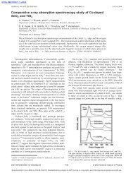
Source<br />
Laser<br />
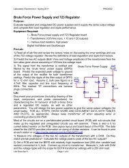
Fig. 5: An amplitude modulator can be used to reduce the amplitude<br />
fluctuations.<br />
Resonant <strong>Modulators</strong><br />
Many applications require modulation at a single,<br />
fixed frequency. The frequency required in the specific<br />
application can vary from a few kilohertz to many<br />
gigahertz. In these cases, true impedance matching<br />
can be achieved, <strong>and</strong> the required drive voltage can be<br />
reduced, by using a resonant circuit. The simplest type<br />
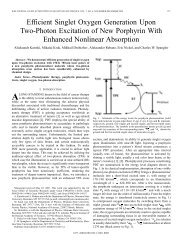
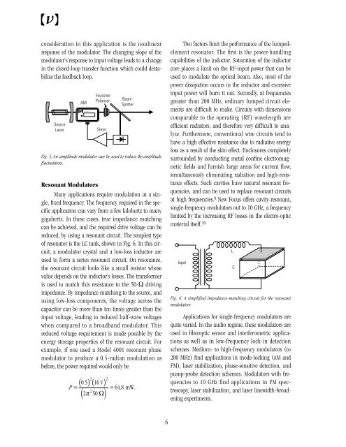
<strong>of</strong> resonator is the LC tank, shown in Fig. 6. In this circuit,<br />
a modulator crystal <strong>and</strong> a low-loss inductor are<br />
used to form a series resonant circuit. On resonance,<br />
the resonant circuit looks like a small resistor whose<br />
value depends on the inductor’s losses. The transformer<br />
is used to match this resistance to the 50-Ω driving<br />
impedance. By impedance matching to the source, <strong>and</strong><br />
using low-loss components, the voltage across the<br />
capacitor can be more than ten times greater than the<br />
input voltage, leading to reduced half-wave voltages<br />
when compared to a broadb<strong>and</strong> modulator. This<br />
reduced voltage requirement is made possible by the<br />
energy storage properties <strong>of</strong> the resonant circuit. For<br />
example, if one used a Model 4001 resonant phase<br />
modulator to produce a 0.5-radian modulation as<br />
before, the power required would only be<br />
P<br />
AM<br />
Feussner <br />
Polarizer<br />
Servo<br />
2 2<br />
( 05 . ) ( 16 V ) =<br />
( π ) =<br />
2<br />
2 50 Ω<br />
Beam <br />
Splitter<br />
( )<br />
648<br />
. mW.<br />
Two factors limit the performance <strong>of</strong> the lumpedelement<br />
resonator. The first is the power-h<strong>and</strong>ling<br />
capabilities <strong>of</strong> the inductor. Saturation <strong>of</strong> the inductor<br />
core places a limit on the RF-input power that can be<br />
used to modulate the optical beam. Also, most <strong>of</strong> the<br />
power dissipation occurs in the inductor <strong>and</strong> excessive<br />
input power will burn it out. Secondly, at frequencies<br />
greater than 200 MHz, ordinary lumped circuit elements<br />
are difficult to make. Circuits with dimensions<br />
comparable to the operating (RF) wavelength are<br />
efficient radiators, <strong>and</strong> therefore very difficult to analyze.<br />
Furthermore, conventional wire circuits tend to<br />
have a high effective resistance due to radiative energy<br />
loss as a result <strong>of</strong> the skin effect. Enclosures completely<br />
surrounded by conducting metal confine electromagnetic<br />
fields <strong>and</strong> furnish large areas for current flow,<br />
simultaneously eliminating radiation <strong>and</strong> high-resistance<br />
effects. Such cavities have natural resonant frequencies,<br />
<strong>and</strong> can be used to replace resonant circuits<br />
at high frequencies. 9 New Focus <strong>of</strong>fers cavity-resonant,<br />
single-frequency modulators out to 10 GHz, a frequency<br />
limited by the increasing RF losses in the electro-optic<br />
material itself. 10<br />
Input<br />
Fig. 6: A simplified impedance-matching circuit for the resonant<br />
modulators.<br />
<strong>Applications</strong> for single-frequency modulators are<br />
quite varied. In the audio regime, these modulators are<br />
used in fiberoptic sensor <strong>and</strong> interferometric applications<br />
as well as in low-frequency lock-in detection<br />
schemes. Medium- to high-frequency modulators (to<br />
200 MHz) find applications in mode-locking (AM <strong>and</strong><br />
FM), laser stabilization, phase-sensitive detection, <strong>and</strong><br />
pump-probe detection schemes. <strong>Modulators</strong> with frequencies<br />
to 10 GHz find applications in FM spectroscopy,<br />
laser stabilization, <strong>and</strong> laser linewidth-broadening<br />
experiments.<br />
L<br />
C<br />
6