Practical Uses and Applications of Electro-Optic Modulators
Practical Uses and Applications of Electro-Optic Modulators
Practical Uses and Applications of Electro-Optic Modulators

You also want an ePaper? Increase the reach of your titles
YUMPU automatically turns print PDFs into web optimized ePapers that Google loves.
Application Note 2<br />
<strong>Practical</strong> <strong>Uses</strong> <strong>and</strong> <strong>Applications</strong><br />
<strong>of</strong> <strong>Electro</strong>-<strong>Optic</strong> <strong>Modulators</strong><br />
NEW FOCUS, Inc.
<strong>Practical</strong> <strong>Uses</strong> <strong>and</strong> <strong>Applications</strong> <strong>of</strong> <strong>Electro</strong>-<strong>Optic</strong> <strong>Modulators</strong><br />
<strong>Electro</strong>-optic amplitude <strong>and</strong> phase modulators<br />
allow you to control the amplitude, phase, <strong>and</strong> polarization<br />
state <strong>of</strong> an optical beam electrically. For instance,<br />
in communications systems, these modulators<br />
impress information onto an optical frequency carrier.<br />
Unlike direct modulation <strong>of</strong> the laser itself, external<br />
modulators do not cause any degrading effects on laser<br />
linewidth <strong>and</strong> stability. In measurement systems,<br />
amplitude modulators can be used as actuators to hold<br />
the intensity in a laser beam constant, or as optical<br />
choppers to produce a pulse stream from a CW laser<br />
beam. Phase modulators are used to stabilize the frequency<br />
<strong>of</strong> a laser beam, or to mode-lock a laser.<br />
There are basically two types <strong>of</strong> modulators: bulk<br />
<strong>and</strong> integrated-optic. Bulk modulators are made out <strong>of</strong><br />
discrete pieces <strong>of</strong> nonlinear optical crystals <strong>and</strong> are typically<br />
used on a lab bench or an optical table. They feature<br />
very low insertion losses, <strong>and</strong> high power-h<strong>and</strong>ling<br />
capability. Integrated-optic modulators, because they<br />
use waveguide technology to lower the required drive<br />
voltages, are wavelength specific. Unlike bulk modulators,<br />
these modulators are fiber pigtailed <strong>and</strong> compact.<br />
After a brief discussion on the electro-optic effect,<br />
Part I <strong>of</strong> this application note will describe the use <strong>and</strong><br />
application <strong>of</strong> bulk modulators. Part II <strong>of</strong> this application<br />
note will discuss integrated-optic modulators.<br />
The <strong>Electro</strong>-<strong>Optic</strong> Effect<br />
The linear electro-optic effect is the change in the<br />
index <strong>of</strong> refraction that is proportional to the magnitude<br />
<strong>of</strong> an externally applied electric field. 1 The effect <strong>of</strong><br />
an applied electric field on the index <strong>of</strong> refraction, seen<br />
by an optical beam polarized in an arbitrary direction<br />
in a crystal, is described by a third-rank tensor. 2<br />
Ignoring the vector nature <strong>of</strong> the physical quantities,<br />
the effect <strong>of</strong> an external electric field on the index <strong>of</strong><br />
refraction <strong>of</strong> a crystal has the form<br />
∆n<br />
= 0<br />
3<br />
n r E<br />
2<br />
where ∆n is the change in the index <strong>of</strong> refraction, n o is<br />
the unperturbed index <strong>of</strong> refraction, r is the appropriate<br />
element in the electro-optic tensor, <strong>and</strong> E is the applied<br />
electric field. This effect is small even in the few crystals<br />
with large electro-optic coefficients. For example, an<br />
electric field <strong>of</strong> 10 6 V/m applied to a crystal <strong>of</strong> lithium<br />
niobate will produce a fractional index change <strong>of</strong><br />
roughly 0.01%. It is rare to see fractional index changes<br />
greater than 1%.<br />
Part I: Bulk <strong>Modulators</strong><br />
New Focus manufactures electro-optic amplitude<br />
<strong>and</strong> phase modulators using lithium niobate, LiNbO 3 ,<br />
<strong>and</strong> lithium tantalate, LiTaO 3 —two crystals with high<br />
electro-optic coefficients <strong>and</strong> good optical <strong>and</strong> electrical<br />
properties. These crystals are grown in large, low scatter-loss<br />
boules, <strong>and</strong> have a wide transparency window.<br />
They are also nonhygroscopic so they can be left on an<br />
optical table for indefinite periods without being in a<br />
sealed enclosure.<br />
Phase Modulation<br />
The phase modulator is the simplest electro-optic<br />
modulator. Here, an electric field is applied along one<br />
<strong>of</strong> the crystal’s principal axes. 3 Light polarized along<br />
any other principal axis experiences an index <strong>of</strong> refraction<br />
change, hence an optical path length change, that<br />
is proportional to the applied electric field. The phase <strong>of</strong><br />
the optical field exiting from the crystal therefore<br />
depends on the applied electric field. The most common<br />
bulk phase modulator is the transverse modulator,<br />
as shown in Fig. 1, which consists <strong>of</strong> an electro-optic<br />
crystal between parallel electrodes. These modulators<br />
develop large electric fields between the electrodes while<br />
simultaneously providing a long interaction length, l,<br />
in which to accumulate phase shift. The optical phase<br />
shift, ∆φ, obtained from applying a voltage, V, between<br />
the electrodes is given by<br />
n0<br />
rV l<br />
∆φ= π ⋅<br />
λ d<br />
whereλ<br />
is the free-space wavelength, <strong>and</strong> d is the elec-<br />
3<br />
2
trode separation. A commonly used figure <strong>of</strong> merit for<br />
electro-optic modulators is the half-wave voltage,<br />
V π<br />
. It is defined as the voltage required to produce an<br />
electro-optic phase shift <strong>of</strong> 180°. Substituting into the<br />
preceding equation yields<br />
for a transverse phase modulator.<br />
It is important to note that the properties <strong>of</strong> a<br />
phase-modulated optical beam do not differ in any way<br />
from those <strong>of</strong> any other phase-modulated carrier wave. 4<br />
Most importantly, phase modulation cannot be separated<br />
from frequency modulation. The instantaneous<br />
frequency <strong>of</strong> a periodic signal is defined as the time<br />
derivative <strong>of</strong> the overall phase <strong>of</strong> the signal. Therefore,<br />
for a phase-modulated signal<br />
where f(t) is the instantaneous frequency, ∆φ(t) is the<br />
signal’s global phase, <strong>and</strong> ω is the optical frequency.<br />
Given a phase modulation ∆φ(t)= msinΩ<br />
t where m is<br />
the phase-modulation index, sinusoidal phase modulation<br />
results in sinusoidal frequency modulation at a<br />
fixed frequency Ω, but with a 90° phase lag <strong>and</strong> a<br />
peak-to-peak excursion <strong>of</strong> 2m Ω.<br />
The phase-modulated field amplitude can be represented<br />
as a set <strong>of</strong> Fourier components in which power<br />
exists only at the discrete optical frequenciesω ± kΩ<br />
E<br />
]<br />
pm<br />
≡ E e<br />
o<br />
p [ ]<br />
d t d t<br />
( t )<br />
Φ( ) φ<br />
≡ = +<br />
( )<br />
ω<br />
2π f<br />
i[ ωt+<br />
msin Ω t]<br />
⎧ ∞<br />
∞<br />
ikΩt k −ikΩt<br />
⎫ i<br />
≡ Eo⎨∑<br />
Jk( m) e + ∑( −1) Jk( m)<br />
e ⎬e<br />
⎩k=<br />
0<br />
k=<br />
0<br />
⎭<br />
where k is an integer, m is the phase-modulation index<br />
(modulation depth) <strong>and</strong> J k (m) is the ordinary Bessel<br />
function <strong>of</strong> order k.<br />
In the case <strong>of</strong> small modulation index, m
espectively. The relationship between the transmission<br />
<strong>and</strong> applied field is not linear but rather has a sin 2<br />
dependence. To obtain linear amplitude modulation,<br />
these modulators are <strong>of</strong>ten biased at 50% transmission<br />
<strong>and</strong> only operated with small applied voltages.<br />
Two ways to bias the modulators are by one, adding a<br />
DC voltage through a bias tee, or two, adding a quarterwave<br />
plate before the analyzer. The voltage required to<br />
bias the modulator at 50% transmission without a<br />
quarter-wave plate is the quarter-wave voltage <strong>of</strong> the<br />
modulator. It has a similar form to the quarter-wave<br />
voltage <strong>of</strong> the transverse phase modulator.<br />
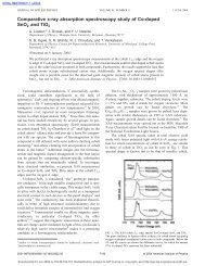
Polarizer<br />
Polarizer<br />
45° Vertical E-Field<br />
<br />
-45°<br />
<br />
<strong>Electro</strong>-optic Crystal<br />
Fig. 2: An amplitude modulator in its simplest form consists <strong>of</strong> an<br />
electro-optic crystal between two crossed polarizers. The signal is<br />
applied as a voltage across electrodes on the top <strong>and</strong> bottom <strong>of</strong> the<br />
electro-optic crystal.<br />
This simple geometry is not practical with most<br />
electro-optic crystals, due to the temperature dependence<br />
<strong>of</strong> these crystals’ birefringence. This dependence<br />
introduces a temperature-dependent waveplate into the<br />
modulator. Consequently, the transmission <strong>of</strong> an uncompensated<br />
modulator using birefringent nonlinear<br />
media (such as LiNbO 3 , or LiTaO 3 ) will exhibit substantial<br />
thermal drift. This temperature sensitivity<br />
can be overcome by either stabilizing the temperature<br />
<strong>of</strong> a single-crystal modulator, or by using two identical<br />
crystals. The second scheme employs two equal-length<br />
crystals placed optically in series with their principal<br />
axes rotated 90° with respect to each other, as seen in<br />
Fig. 3. The optical beam’s polarization components<br />
therefore travel equal path lengths in each <strong>of</strong> the two<br />
index regions, which leads to a structure with zero birefringence,<br />
independent <strong>of</strong> temperature. Thermal drift<br />
limits the usefulness <strong>of</strong> a phase modulator, which is<br />
typically made out <strong>of</strong> a single crystal.<br />
Two Orthogonal<br />
Polarizer<br />
<strong>Electro</strong>-optic Crystals<br />
Polarizer<br />
45° -45°<br />
<strong>Electro</strong>des<br />
<br />
Fig. 3: Thermal bias drift can be passively compensated using two<br />
crystals oriented orthogonally with respect to each other. In the case<br />
shown above, the crystals are mounted at 45°. Thus, the input polarization<br />
is vertical. The applied field is reversed in the second crystal.<br />
In this manner, the thermal birefringence is compensated but the<br />
desired birefringence is doubled.<br />
<strong>Practical</strong> Limitations<br />
There are several practical limits on the performance<br />
<strong>of</strong> these devices. Mainly, the optical power<br />
h<strong>and</strong>ling capability <strong>of</strong> LiNbO 3 <strong>and</strong> LiTaO 3 is limited<br />
by an effect known as photorefractive damage.<br />
Although this effect is sometimes useful (as in holographic<br />
data storage) <strong>and</strong> does not permanently damage<br />
the crystals, it can degrade the performance <strong>of</strong> a<br />
modulator. A modulator with a photorefractively damaged<br />
crystal will distort an optical beam passing<br />
through it. 7 The best way to avoid photorefractive damage<br />
is to keep the optical intensity below the specified<br />
limit for the modulator. Since the photorefractive effect<br />
is highly wavelength dependent, modulators can h<strong>and</strong>le<br />
correspondingly higher powers at longer wavelengths.<br />
New Focus also uses LiNbO 3 that has been<br />
doped with magnesium-oxide (Mg-O). This new material<br />
exhibits far superior power-h<strong>and</strong>ling capability.<br />
Another limitation results from the fact that all<br />
materials with nonzero electro-optic coefficients are<br />
also piezoelectric. This means that the same electrical<br />
signal that produces phase modulation also generates<br />
vibrations. Strains induced by these vibrations alter the<br />
indices <strong>of</strong> refraction via the elasto-optic effect. These<br />
vibrations can cause unwanted amplitude modulation<br />
or beam displacements at the modulation frequency.<br />
The piezoelectric constants <strong>of</strong> LiTaO 3 <strong>and</strong> LiNbO 3 are<br />
fairly weak, <strong>and</strong> typically do not affect the performance<br />
<strong>of</strong> the crystals as long as the mechanical resonance frequencies<br />
(typically between 1 <strong>and</strong> 10 MHz) are avoided.<br />
New Focus will not ship single-frequency modulators<br />
tuned near a piezoelectric resonance.<br />
4
A third limitation when using a phase modulator<br />
is residual amplitude modulation. An ideal<br />
phase modulator should not modulate the intensity <strong>of</strong><br />
an optical beam. Amplitude modulation will be<br />
induced by sources <strong>of</strong> back-reflection placed after the<br />
phase modulator. Back-reflections result in weak<br />
étalons which will alter the harmonic content <strong>of</strong> the<br />
modulated optical beam by introducing a measurable<br />
amplitude modulation component onto the beam.<br />
Unwanted amplitude modulation can be minimized by<br />
properly aligning the input polarization state to the<br />
principal axis <strong>of</strong> the modulator, which is vertical in the<br />
case <strong>of</strong> New Focus modulators. You can further reduce<br />
residual amplitude modulation by using a collimated<br />
optical beam positioned down the center <strong>of</strong> the modulator.<br />
To enable quick <strong>and</strong> easy alignment <strong>of</strong> its modulators,<br />
New Focus <strong>of</strong>fers the Model 4902 tilt aligner.<br />
Broadb<strong>and</strong> <strong>Modulators</strong><br />
New Focus <strong>of</strong>fers modulators designed to modulate<br />
either the amplitude or phase <strong>of</strong> linearly polarized<br />
light over a wide b<strong>and</strong>width, from DC to roughly<br />
100 MHz, with a relatively low drive voltage. The electrical<br />
input impedance <strong>of</strong> these devices in this frequency<br />
range is dominated by the capacitance <strong>of</strong> the electrooptic<br />
crystal. This capacitance ranges from 10 pF for<br />
the Model 4104 amplitude modulator to 30 pF for the<br />
Models 4002 <strong>and</strong> 4004 phase modulators. Signal generators<br />
<strong>and</strong> frequency synthesizers typically have 50-Ω<br />
output impedances, <strong>and</strong> are not optimized for driving<br />
capacitive loads. However, since 30 pF is a fairly small<br />
capacitance, most signal generators are adequate drivers<br />
at low frequencies (
484X<br />
YYY Phase Modulator<br />
NEW FOCUS Inc. Mountain View, CA<br />
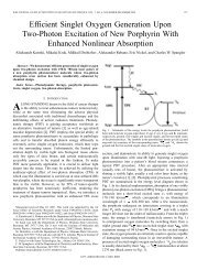
consideration in this application is the nonlinear<br />
response <strong>of</strong> the modulator. The changing slope <strong>of</strong> the<br />
modulator's response to input voltage leads to a change<br />
in the closed-loop transfer function which could destabilize<br />
the feedback loop.<br />
Source<br />
Laser<br />
Fig. 5: An amplitude modulator can be used to reduce the amplitude<br />
fluctuations.<br />
Resonant <strong>Modulators</strong><br />
Many applications require modulation at a single,<br />
fixed frequency. The frequency required in the specific<br />
application can vary from a few kilohertz to many<br />
gigahertz. In these cases, true impedance matching<br />
can be achieved, <strong>and</strong> the required drive voltage can be<br />
reduced, by using a resonant circuit. The simplest type<br />
<strong>of</strong> resonator is the LC tank, shown in Fig. 6. In this circuit,<br />
a modulator crystal <strong>and</strong> a low-loss inductor are<br />
used to form a series resonant circuit. On resonance,<br />
the resonant circuit looks like a small resistor whose<br />
value depends on the inductor’s losses. The transformer<br />
is used to match this resistance to the 50-Ω driving<br />
impedance. By impedance matching to the source, <strong>and</strong><br />
using low-loss components, the voltage across the<br />
capacitor can be more than ten times greater than the<br />
input voltage, leading to reduced half-wave voltages<br />
when compared to a broadb<strong>and</strong> modulator. This<br />
reduced voltage requirement is made possible by the<br />
energy storage properties <strong>of</strong> the resonant circuit. For<br />
example, if one used a Model 4001 resonant phase<br />
modulator to produce a 0.5-radian modulation as<br />
before, the power required would only be<br />
P<br />
AM<br />
Feussner <br />
Polarizer<br />
Servo<br />
2 2<br />
( 05 . ) ( 16 V ) =<br />
( π ) =<br />
2<br />
2 50 Ω<br />
Beam <br />
Splitter<br />
( )<br />
648<br />
. mW.<br />
Two factors limit the performance <strong>of</strong> the lumpedelement<br />
resonator. The first is the power-h<strong>and</strong>ling<br />
capabilities <strong>of</strong> the inductor. Saturation <strong>of</strong> the inductor<br />
core places a limit on the RF-input power that can be<br />
used to modulate the optical beam. Also, most <strong>of</strong> the<br />
power dissipation occurs in the inductor <strong>and</strong> excessive<br />
input power will burn it out. Secondly, at frequencies<br />
greater than 200 MHz, ordinary lumped circuit elements<br />
are difficult to make. Circuits with dimensions<br />
comparable to the operating (RF) wavelength are<br />
efficient radiators, <strong>and</strong> therefore very difficult to analyze.<br />
Furthermore, conventional wire circuits tend to<br />
have a high effective resistance due to radiative energy<br />
loss as a result <strong>of</strong> the skin effect. Enclosures completely<br />
surrounded by conducting metal confine electromagnetic<br />
fields <strong>and</strong> furnish large areas for current flow,<br />
simultaneously eliminating radiation <strong>and</strong> high-resistance<br />
effects. Such cavities have natural resonant frequencies,<br />
<strong>and</strong> can be used to replace resonant circuits<br />
at high frequencies. 9 New Focus <strong>of</strong>fers cavity-resonant,<br />
single-frequency modulators out to 10 GHz, a frequency<br />
limited by the increasing RF losses in the electro-optic<br />
material itself. 10<br />
Input<br />
Fig. 6: A simplified impedance-matching circuit for the resonant<br />
modulators.<br />
<strong>Applications</strong> for single-frequency modulators are<br />
quite varied. In the audio regime, these modulators are<br />
used in fiberoptic sensor <strong>and</strong> interferometric applications<br />
as well as in low-frequency lock-in detection<br />
schemes. Medium- to high-frequency modulators (to<br />
200 MHz) find applications in mode-locking (AM <strong>and</strong><br />
FM), laser stabilization, phase-sensitive detection, <strong>and</strong><br />
pump-probe detection schemes. <strong>Modulators</strong> with frequencies<br />
to 10 GHz find applications in FM spectroscopy,<br />
laser stabilization, <strong>and</strong> laser linewidth-broadening<br />
experiments.<br />
L<br />
C<br />
6
Part 2: Integrated-<strong>Optic</strong> <strong>Modulators</strong><br />
Like the bulk modulator, the integrated-optic<br />
modulator also works on the principle <strong>of</strong> the linear<br />
electro-optic effect. 11 All New Focus integrated-optic<br />
devices are made from lithium niobate (LiNbO 3 ),<br />
because <strong>of</strong> its relatively high electro-optic coefficient<br />
<strong>and</strong> high-quality crystals. An integrated-optic<br />
phase modulator is simply constructed using a<br />
dielectric optical waveguide <strong>and</strong> the linear electro-optic<br />
effect to control the index <strong>of</strong> refraction <strong>of</strong> the waveguide<br />
(Fig. 7). In the presence <strong>of</strong> an electric field, light<br />
traveling through this material will experience a<br />
change in propagation delay, ∆t=(∆nL)/c, which is<br />
equivalent to a change in the phase <strong>of</strong> the light at the<br />
output as given by<br />
∆φ= ω∆t=(∆nω<br />
L)/c<br />
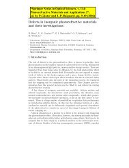
(push-pull configuration) results in an electric field<br />
with opposite polarity across the two paths <strong>of</strong> the interferometer.<br />
Positive <strong>and</strong> negative electric fields change<br />
the index <strong>of</strong> refraction in opposite directions, increase<br />
the relative phase shift in one path, <strong>and</strong> decrease it in<br />
the other path. Total transmission occurs for a 0˚ net<br />
phase difference, <strong>and</strong> total extinction occurs for a 180˚<br />
net phase difference between the two paths. For an ideal<br />
amplitude modulator, the optical power at the output <strong>of</strong><br />
the modulator is P out =1/2 P in [1+cos( ∆φ )] where P in<br />
is the input optical power <strong>and</strong> ∆φ is the phase difference<br />
between the two paths. An amplitude modulator is<br />
<strong>of</strong>ten biased at the half-power point (or quadraturepoint)<br />
for linear operation.<br />
(a)<br />
Y<br />
where ∆n is the absolute change in index <strong>of</strong> refraction<br />
due to the applied electric field, ω is the optical frequency,<br />
L is the interaction length, <strong>and</strong> c is the speed <strong>of</strong><br />
light in a vacuum.<br />
(b)<br />
1.00<br />
AM-DC<br />
<strong>Electro</strong>de<br />
AM-RF<br />
<strong>Electro</strong>de<br />
(a)<br />
V RF<br />
P out<br />
P in<br />
0.50<br />
Quadrature Point<br />
(b)<br />
<strong>Electro</strong>des<br />
→<br />
E Light<br />
0.00<br />
0.00 π/2 π 3π/2 2π<br />
∆φ<br />
→<br />
E RF<br />
Lithium Niobate<br />
Waveguide<br />
Fig. 7: Integrated-optic phase modulator (a) top view, <strong>and</strong> (b) side<br />
view<br />
Amplitude modulators are constructed by<br />
patterning a Mach-Zehnder interferometer on a LiNbO 3<br />
substrate (Fig. 8). The input optical waveguide is split<br />
into two paths <strong>and</strong> then recombined. A voltage applied<br />
to the center electrode with the side electrodes grounded<br />
Fig. 8: Mach-Zehnder amplitude modulator (a) top view, <strong>and</strong> (b)<br />
transfer function.<br />
Other configurations are also commercially<br />
available depending on the particular applications. For<br />
example, there are modulators with both phase <strong>and</strong><br />
amplitude sections on the same chip (Fig. 9a).<br />
Complementary-output amplitude modulators have<br />
been designed for use in signal processing <strong>and</strong> cable<br />
television applications (Fig. 9b). One output is used for<br />
transmission while the other output can be used either<br />
for transmission or in a feedback control system to stabilize<br />
thermal drift <strong>and</strong> minimize harmonic distortion.<br />
7
<strong>Modulators</strong> have also been designed for fiber-optic<br />
gyroscope applications (Fig. 9c). Even though these<br />
modulators are more complex than a basic phase modulator,<br />
they still operate using the basic principle <strong>of</strong> the<br />
linear electro-optic effect.<br />
(a)<br />
(b)<br />
(c)<br />
Light<br />
In<br />
Phase<br />
Modulator<br />
PM RF<br />
VRF<br />
AM DC<br />
VBias<br />
Amplitude<br />
Modulator<br />
AM RF<br />
Fig. 9: (a) Amplitude <strong>and</strong> phase modulator on same chip, (b) complementary-output<br />
amplitude modulator, <strong>and</strong> (c) modulator for<br />
fiber-optic gyroscope systems.<br />
Advantages <strong>of</strong> Integrated-<strong>Optic</strong> <strong>Modulators</strong><br />
Integrated-optic modulators require lower drive<br />
voltages <strong>and</strong> operate at higher frequencies than bulk<br />
modulators. Because <strong>of</strong> their small size <strong>and</strong> compatibility<br />
with single-mode optical fiber, they have been<br />
used in a variety <strong>of</strong> communication <strong>and</strong> sensor applications.<br />
Their disadvantages, compared to bulk modulators,<br />
include lower maximum optical power <strong>and</strong><br />
incompatibility with free-space beams. However these<br />
have not limited the impressive results achieved. The<br />
following list, though not comprehensive, illustrates<br />
the wide variety <strong>of</strong> applications for integrated-optic<br />
modulators. 12<br />
Phase modulators have been used in digital optical<br />
communication experiments using 4-Gb/s phaseshift<br />
keyed (PSK) modulation, 4-Gb/s differential<br />
phase-shift keyed (DPSK) modulation <strong>and</strong> 8-Gb/s<br />
quadrature phase-shift keyed (QPSK) modulation.<br />
Amplitude modulators have been used in a 770 km,<br />
3 db<br />
V 1<br />
V2<br />
PM DC<br />
Modulated <br />
Light <br />
Out<br />
Output 1<br />
Output 2<br />
2.5-Gb/s long-distance optical-communication experiment,<br />
a 20-GHz analog link, a 50-channel AM video<br />
transmission demonstration, <strong>and</strong> a novel optical clock<br />
recovery scheme. In addition, more complex integratedoptic<br />
modulators are also seen in many applications.<br />
<strong>Modulators</strong> with both phase <strong>and</strong> amplitude sections<br />
integrated on the same chip (Fig. 9a) have been used<br />
to transmit 125-Mb/s amplitude shift-keyed (ASK) data<br />
<strong>and</strong> 2.488-Gb/s PSK data simultaneously on the same<br />
lightwave. Also, multi-function integrated-optic modulators,<br />
similar to the one in Fig. 9c, are being used in<br />
advanced fiber-optic gyroscope experiments.<br />
Details about Integrated-<strong>Optic</strong> <strong>Modulators</strong><br />
There are two main processes for patterning single-mode<br />
optical waveguides on LiNbO 3 : titanium<br />
(Ti) indiffusion <strong>and</strong> annealed proton exchange<br />
(APE ). In both cases, the waveguide pattern<br />
is defined on the surface <strong>of</strong> a LiNbO 3 crystal using photolithography.<br />
The more developed approach is titanium<br />
indiffusion. To create a titanium waveguide, Ti is<br />
diffused through a mask into the substrate at a temperature<br />
near 1000˚ C. This results in a permanent<br />
increase in the refractive index that guides the light in<br />
both width <strong>and</strong> depth. Titanium waveguides support<br />
both transverse electric (TE) <strong>and</strong> transverse magnetic<br />
(TM) optical polarizations. The APE process is an alternative<br />
to titanium indiffusion. It creates a much larger<br />
refractive index increase (5% vs. 0.5% for Ti<br />
indiffusion), but guides only one polarization. Also, it is<br />
more resistant to optical damage. APE waveguides are<br />
created by exchanging H + ions (protons) for Li + ions in<br />
the LiNbO 3 crystal by placing the patterned crystal in a<br />
proton-rich melt such as benzoic acid. The LiNbO 3 is<br />
then annealed for a few hours to cause further diffusion<br />
<strong>of</strong> the protons.<br />
Lithium niobate is an anisotropic, uniaxial crystal<br />
with n o =n x =n y =2.23 <strong>and</strong> n e =n z =2.15, where n o<br />
is the ordinary index <strong>of</strong> refraction <strong>and</strong> n e is the extraordinary<br />
index <strong>of</strong> refraction. Due to the crystal symmetry<br />
in LiNbO 3 , there are two useful crystal orientations,<br />
Z-cut <strong>and</strong> X-cut (Fig. 10), which take advantage <strong>of</strong><br />
the strongest electro-optic coefficient (r 33 in the Z direction).<br />
A Z-cut device uses the vertical component <strong>of</strong> the<br />
8
electric field, <strong>and</strong> an X-cut device uses the horizontal<br />
component. For a Z-cut device, an optical isolation<br />
layer is required to avoid increased optical losses since<br />
one <strong>of</strong> the electrodes is placed on top <strong>of</strong> the optical<br />
waveguide. All New Focus modulators use an X-cut<br />
crystal orientation in order to provide temperature stability<br />
<strong>and</strong> a propagation direction that utilizes the<br />
largest electro-optic coefficient.<br />
X<br />
Z<br />
E-field<br />
Lithium Niobate<br />
E-field<br />
Y<br />
X-cut<br />
Lithium Niobate<br />
Z-cut<br />
Waveguide<br />
Waveguide<br />
Fig. 10: Geometry <strong>of</strong> LiNbO 3 modulators.<br />
X<br />
Z<br />
Y<br />
To create a well-defined electric field within the<br />
optical waveguide, thick gold electrodes are deposited<br />
on the LiNbO 3 substrate. The modulation b<strong>and</strong>width<br />
<strong>of</strong> an integrated-optic modulator depends on the type <strong>of</strong><br />
electrode. Lower frequency modulators use lumped-element<br />
electrodes where the electrode length is small<br />
compared to the drive-signal wavelength. The modulation<br />
b<strong>and</strong>width is limited by the RC time constant <strong>of</strong><br />
the electrode capacitance <strong>and</strong> the parallel matching<br />
resistance. The parallel matching resistance is normally<br />
set to 50 Ω to allow broadb<strong>and</strong> matching to a 50-Ω<br />
driving source. It is very difficult to build a lumped-element<br />
modulator with a b<strong>and</strong>width much higher than<br />
1 GHz. The modulation b<strong>and</strong>width can be improved by<br />
using traveling-wave electrodes at the expense <strong>of</strong><br />
fabrication simplicity. Traveling-wave electrodes are<br />
designed as transmission lines, fed at one end <strong>and</strong> terminated<br />
with a resistive load at the other end. With<br />
traveling-wave electrodes, the modulator b<strong>and</strong>width is<br />
limited by the difference between the optical <strong>and</strong> RF<br />
signal’s transit times across the crystal rather than the<br />
lumped-element RC time constant. Much effort has<br />
been put into designing traveling-wave modulators<br />
where the RF <strong>and</strong> optical signals travel at the same<br />
speed, <strong>and</strong> thus, have a high b<strong>and</strong>width. Research<br />
devices have been demonstrated with over 40 GHz <strong>of</strong><br />
electrical b<strong>and</strong>width. 11 A modulator with resistively<br />
matched, traveling-wave electrodes can operate down<br />
to DC. If the traveling-wave electrodes are transformer<br />
matched, the required drive voltage is lowered, but the<br />
modulator becomes a b<strong>and</strong>-pass device <strong>and</strong> will not<br />
work down to DC.<br />
The optical wavelength <strong>of</strong> the modulator<br />
must be specified, because the waveguides <strong>and</strong> electrodes<br />
are optimized for a particular wavelength.<br />
Wavelengths that are commonly available are 1.3 µm<br />
<strong>and</strong> 1.5 µm corresponding to the low-loss windows <strong>of</strong><br />
single-mode optical fiber.<br />
For maximum efficiency, the input optical field<br />
must have a linear polarization properly aligned<br />
with the modulating electric field. Modulator chips are<br />
typically connected to polarization-maintaining (PM)<br />
fiber at the input <strong>and</strong> either PM fiber or single-mode<br />
(SM) fiber at the output using UV-curable adhesive.<br />
These fibers are commonly referred to as pigtails. To<br />
reduce optical reflections, the modulator chip is antireflection<br />
(AR) coated or angle-polished before connecting<br />
the pigtails. <strong>Optic</strong>al return loss is the ratio<br />
<strong>of</strong> the back-reflected optical power in the input fiber to<br />
the input optical power, expressed in dB. The backreflected<br />
light is generated at the interface between the<br />
fiber pigtail <strong>and</strong> the LiNbO 3 crystal. With an angle-polish,<br />
the incident light is reflected at an angle <strong>and</strong> very<br />
little reflected light is coupled back into the input fiber.<br />
The optical return loss should be less than -30 dB for<br />
most applications.<br />
Insertion loss is the optical power loss in the<br />
modulator expressed in dB. It is measured as the ratio<br />
<strong>of</strong> optical power in the input fiber to the optical power<br />
in the output fiber when the modulator is biased for<br />
maximum transmission. This value accounts for the<br />
9
loss between the fiber pigtails <strong>and</strong> the modulator, as<br />
well as the loss in the modulator itself. Insertion loss<br />
should be in the range <strong>of</strong> 4–7 dB. Additional loss may<br />
occur, depending on the method used to couple light<br />
into the fiber pigtails.<br />
Working with Integrated-<strong>Optic</strong> <strong>Modulators</strong><br />
Note: When working with integrated-optic modulators, be aware <strong>of</strong> all<br />
manufacturer-specified safe operating levels. Exceeding the maximum<br />
electrical voltages or optical power can result in permanent<br />
damage to your modulator.<br />
There are a few options for coupling light into a<br />
modulator: fiber-optic connectors, mechanical<br />
splices, fusion splices, or free-space coupling.<br />
When connecting a PM fiber to a PM pigtail, the<br />
axis <strong>of</strong> the two fibers must be properly aligned. If you<br />
do not have experience working with PM fiber, it is easiest<br />
to have the pigtails pr<strong>of</strong>essionally connectorized<br />
with properly aligned connectors. Using connectors is a<br />
stable <strong>and</strong> repeatable method for connecting two<br />
PM fibers. If you have the experience <strong>and</strong> patience to<br />
work with PM fiber, mechanical splices are an alternative<br />
to connectors. Mechanical splices are available<br />
from a variety <strong>of</strong> vendors. Avoid mechanical splices<br />
with mechanical lock-downs. The screws in these types<br />
<strong>of</strong> splices can break the stress rods in PM fibers. Fusion<br />
splicers are very expensive <strong>and</strong> generally not recommended<br />
for PM fiber. In addition, if fusion splicers<br />
align the two fibers in reference to their outer diameter,<br />
the results will vary. The center <strong>of</strong> the core <strong>of</strong> many<br />
PM fibers is not within sufficient tolerance to the outer<br />
diameter to achieve repeatable, low insertion loss. If your<br />
source is a free-space laser beam, then fiber coupling<br />
using a lens <strong>and</strong> fiber positioner is another alternative.<br />
For quick laboratory measurements, an SM fiber<br />
can be temporarily connected to the PM pigtail, but<br />
some type <strong>of</strong> polarization control, such as a mechanical,<br />
fiber polarization-controller, must be used to align<br />
the input optical polarization with the axis <strong>of</strong> the PM<br />
fiber. In addition, the polarization control will have to<br />
be periodically adjusted (on the time scale <strong>of</strong> minutes)<br />
to correct for environmentally induced polarization<br />
fluctuations in the SM fiber.<br />
When selecting an amplifier to drive an integrated-optic<br />
modulator, keep in mind the b<strong>and</strong>width <strong>of</strong><br />
your signal. Some applications are narrow-b<strong>and</strong> <strong>and</strong><br />
others, such as digital optical communications, require<br />
signal components down to DC. Even a pseudo-r<strong>and</strong>om<br />
bit stream (PRBS) can require signal components as<br />
low as 10 -4 to 10 -6 times the data rate. So a 3-Gb/s nonreturn<br />
to zero (NRZ) data stream could potentially<br />
require a b<strong>and</strong>width from DC to 3 GHz. Also, the output<br />
power <strong>of</strong> the amplifier must be high enough to modulate<br />
your optical signal to the desired depth at all frequencies.<br />
To fully modulate the optical signal requires<br />
an amplifier with an output power <strong>of</strong><br />
( )<br />
⎡ 2<br />
V ⎤<br />
π 2<br />
P = 30 + 10 log ⎢<br />
( / ) out<br />
⎥ dBm.<br />
⎣ 50 ⎦<br />
As an example, consider the same 3-Gb/s NRZ<br />
signal for modulation <strong>of</strong> the amplitude section <strong>of</strong><br />
a New Focus Model 4503 dual function PM & AM modulator.<br />
The V π is 10 V at DC. Therefore, P out <strong>of</strong> the<br />
amplifier must be at least 27 dBm to fully modulate the<br />
optical signal.<br />
Most modulators will come from the supplier<br />
with a data sheet listing measured device parameters<br />
such as insertion loss, V π extinction ratio, <strong>and</strong> possibly,<br />
the optical b<strong>and</strong>width. For an amplitude modulator, V π<br />
<strong>and</strong> its extinction ratio are easy to measure with a good<br />
power meter.<br />
Determining V π<br />
for a phase modulator is not<br />
as simple. One way to indirectly measure V π<br />
is by applying<br />
a sinusoidal-modulation voltage <strong>and</strong> calculating<br />
the modulation depth from the measured spectrum <strong>of</strong><br />
the phase modulated optical field. 13 The electrical<br />
b<strong>and</strong>width can be determined by repeating the measurements<br />
for the amplitude or phase V π at different frequencies.<br />
The 3-dB point is the frequency at which V π<br />
has increased to 2 times its DC value.<br />
Summary<br />
Bulk <strong>and</strong> integrated-optic electro-optic modulators<br />
find uses in a wide variety <strong>of</strong> applications. They<br />
make it easy to modulate the amplitude or phase <strong>of</strong> an<br />
optical signal up to 10’s <strong>of</strong> gigahertz. Bulk modulators<br />
are well-suited for applications with high optical powers<br />
or broad spectral b<strong>and</strong>width requirements.<br />
10
Integrated-optic devices operate within 10% <strong>of</strong> the center<br />
wavelength, <strong>and</strong> are available in many configurations<br />
for a variety <strong>of</strong> applications such as digital optical<br />
communications, analog video transmission, <strong>and</strong> fiber<br />
sensors. Underst<strong>and</strong>ing how these modulators work<br />
<strong>and</strong> how to work with them will allow you to make<br />
your measurements <strong>and</strong> develop your systems in the<br />
most efficient <strong>and</strong> accurate way.<br />
References<br />
1 For further information on the electro-optic effect<br />
see A. Yariv, <strong>Optic</strong>al <strong>Electro</strong>nics, 3 rd edition, Ch. 9,<br />
or A. Yariv <strong>and</strong> P. Yeh, <strong>Optic</strong>al Waves In Crystals,<br />
New York: John Wiley & Sons, 1984.<br />
2 For example, Yariv, pp. 280–283.<br />
3 For more background on birefringent crystals, see<br />
New Focus Application Note 3 on polarization.<br />
4 See the analysis in A. B. Carlson, Communications<br />
Systems, Ch. 6.<br />
5 An introduction to laser mode-locking is found in<br />
A. Siegman, Lasers, Ch. 27.<br />
6 Waveplates are described in New Focus Application<br />
Note 3 on polarization.<br />
7 See T. J. Hall, R. Jaura, L. M. Connors, <strong>and</strong> P. D.<br />
Foote, “The Photorefractive Effect—A Review,” in<br />
Prog. Quantum Elect. 10, pp. 77–146.<br />
8 For an introduction to transmission line theory, D.<br />
Cheng, Field <strong>and</strong> Wave <strong>Electro</strong>magnetics, Ch. 9.<br />
9 Resonant cavities are discussed in S. Ramo, J.R.<br />
Whinnery, <strong>and</strong> T. Van Duzer, Fields <strong>and</strong> Waves in<br />
Communication <strong>Electro</strong>nics, 2 nd edition, Ch. 10.<br />
10 For more background on high-frequency modulators,<br />
ask for a reprint <strong>of</strong> T. Day, Laser Focus World,<br />
“Single Frequency Bulk <strong>Electro</strong>-<strong>Optic</strong> <strong>Modulators</strong>.”<br />
11 For more information on integrated-optic modulators,<br />
S. E. Miller <strong>and</strong> I. P. Kaminow, Ed., <strong>Optic</strong>al<br />
Fiber Telecomm. II, San Diego: Academic Press,<br />
1988; or R. C. Alferness, “Waveguide electro-optic<br />
modulators,” IEEE Trans. on Micr. Theory <strong>and</strong><br />
Tech., vol. MTT-30, no. 8, pp. 1121–1137, August<br />
1982.<br />
12 Notable experiments using integrated-optic modulators:<br />
D. A. Atlas <strong>and</strong> L. G. Kazovsky, “<strong>Optic</strong>al PSK synchronous<br />
heterodyne experiments at 560 Mbit/s<br />
through 4 Gbit/s,” J. Opt. Comm., vol. 12, no. 4,<br />
pp. 130–137, Dec. 1991.<br />
A. H. Gnauck, K. C. Reichmann, J. M. Kahn, S. K.<br />
Korotky, J. J. Veselka, <strong>and</strong> T. L. Koch, “4-Gb/s heterodyne<br />
transmission experiments using ASK, FSK, <strong>and</strong><br />
DPSK modulation,” IEEE Phot. Tech. Lett., vol. 2,<br />
no. 12, pp. 908–910, Dec. 1990.<br />
S. Norimatsu, K. Iwashita, <strong>and</strong> K. Noguchi, “An<br />
8-Gb/s QPSK optical homodyne detection<br />
experiment using external-cavity laser diodes,”<br />
IEEE Phot. Tech. Lett., vol. 4, no. 7, pp. 765–767,<br />
July 1992.<br />
M. L. Kao, Y. K. Park, T. V. Nguyen, L. D. Tzeng, <strong>and</strong><br />
P. D. Yates, “2.5-Gbit/s Ti:LiNbO 3 external modulator<br />
transmitter <strong>and</strong> its long distance transmission<br />
performance in the field,” <strong>Electro</strong>n. Lett.,<br />
vol. 28, no. 7, pp. 687–689, March 1992.<br />
G. E. Betts, C. H. Cox, <strong>and</strong> K. G. Ray, “20-GHz optical<br />
analog link using an external modulator,”<br />
IEEE Phot. Tech. Lett., vol. 2, no. 12, pp. 923–925,<br />
Dec. 1990.<br />
R. B. Childs <strong>and</strong> V. A. O’Byrne, “Multichannel AM<br />
video transmission using a high-power Nd:YAG<br />
laser <strong>and</strong> linearized external modulator,” IEEE<br />
J. Sel. Areas Comm., vol. 8, no. 7, pp. 1369–1376,<br />
Sept. 1990.<br />
M. W. Chbat, P. A. Perrier, <strong>and</strong> P. R. Prucnal,<br />
“<strong>Optic</strong>al clock recovery demonstration using<br />
periodic oscillations <strong>of</strong> a hybrid electro-optic<br />
bistable system,” IEEE Phot. Tech. Lett., vol. 3, no. 1,<br />
pp. 65–67, Jan. 1991.<br />
M. Hickey, C. Barry, C. Noronha, <strong>and</strong> L. Kazovsky,<br />
“An experimental PSK/ASK transceiver for a<br />
multi-Gb/s coherent WDM local area network,”<br />
11
presented at OFC ‘93, paper ThM4, San Jose, CA,<br />
Feb. 1993.<br />
H. C. Lefevre, S. Vatoux, M. Papuchon, <strong>and</strong> C. Puech<br />
“Integrated optics: a practical solution for the fiber<br />
optic gyroscope,” Fiber <strong>Optic</strong> Gyros: 10th Ann.<br />
Conf., Proc. SPIE, vol. 719, pp. 101–112, 1986.<br />
D. Dolfi <strong>and</strong> T. Ranganath, “50-GHz velocitymatched<br />
broad wavelength LiNbO 3 modulator with<br />
multimode active section,” <strong>Electro</strong>n. Lett.,<br />
vol. 28, no. 13, pp. 1197–1198, June 1992<br />
13 R. E. Tench, J.-M. P. Delavaux, L. D. Tzeng, R. W.<br />
Smith, L. L. Buhl, <strong>and</strong> R. C. Alferness, “Performance<br />
evaluation <strong>of</strong> waveguide phase modulators for<br />
coherent systems at 1.3 <strong>and</strong> 1.5 mm,” J. Lightwave<br />
Tech., vol. LT-5, no. 4, pp. 492–501, April 1987.<br />
NEW FOCUS, Inc.<br />
2630 Walsh Avenue, Santa Clara, CA 95051-0905<br />
(408) 980-8088 • FAX: (408) 980-8883<br />
E-mail: Contact@NewFocus.com • http://www.NewFocus.com<br />
© New Focus, Inc. 1993<br />
12