Simulated SOFC Interconnect Performance of Crofer 22 APU with ...
Simulated SOFC Interconnect Performance of Crofer 22 APU with ...
Simulated SOFC Interconnect Performance of Crofer 22 APU with ...

Create successful ePaper yourself
Turn your PDF publications into a flip-book with our unique Google optimized e-Paper software.
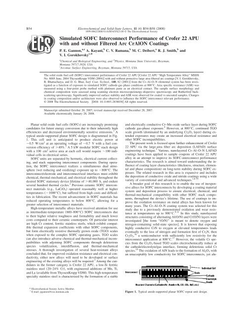
B54<br />
Electrochemical and Solid-State Letters, 11 4 B54-B58 2008<br />
1099-0062/2008/114/B54/5/$23.00 © The Electrochemical Society<br />
<strong>Simulated</strong> <strong>SOFC</strong> <strong>Interconnect</strong> <strong>Performance</strong> <strong>of</strong> Cr<strong>of</strong>er <strong>22</strong> <strong>APU</strong><br />
<strong>with</strong> and <strong>with</strong>out Filtered Arc CrAlON Coatings<br />
P. E. Gannon, a,z A. Kayani, b C. V. Ramana, b M. C. Deibert, a R. J. Smith, b and<br />
V. I. Gorokhovsky c, *<br />
a Chemical and Biological Engineering, and b Physics, Montana State University, Bozeman,<br />
Montana 59717-3920, USA<br />
c Arcomac Surface Engineering, Bozeman, Montana 59715, USA<br />
The solid oxide fuel cell <strong>SOFC</strong> interconnect performance <strong>of</strong> Cr<strong>of</strong>er <strong>22</strong> <strong>APU</strong> Cr<strong>of</strong>er <strong>22</strong> <strong>APU</strong> “High Temperature Alloy” MSDS<br />
No. 8005 June, 2004 ThyssenKrupp VDM 2004 <strong>with</strong> and <strong>with</strong>out protective large area filtered arc coatings V. I. Gorokhovsky,<br />
R. Bhattacharya, and D. G. Bhat, Surf. Coat. Technol., 140, 8<strong>22</strong>001 from the Cr–Al–O–N elemental system has been investigated<br />
as a function <strong>of</strong> exposure to simulated <strong>SOFC</strong> cathode-gas phase conditions at 800°C. Area specific resistance ASR was<br />
measured using a four-point probe method <strong>with</strong> platinum paste as an electrical contact. The sample surface morphology and<br />
chemical composition were assessed using scanning electron microscope/energy-dispersive spectroscopy and Rutherford backscattering<br />
spectroscopy. Significantly improved surface stability and ASR were observed for coated vs uncoated samples. Changes<br />
in coating composition and/or architecture were also observed to influence the <strong>SOFC</strong> interconnect relevant performance.<br />
© 2008 The Electrochemical Society. DOI: 10.1149/1.2838038 All rights reserved.<br />
Manuscript submitted October 20, 2007; revised manuscript received December 28, 2007.<br />
Available electronically January 28, 2008.<br />
Planar solid oxide fuel cells <strong>SOFC</strong>s are increasingly promising<br />
candidates for future energy conversion due to their inherently high<br />
efficiencies and decreased environmentally sensitive emissions. 1 A<br />
typical anode-supported planar <strong>SOFC</strong> design is diagrammed in Fig.<br />
1. This cell unit is anticipated to produce electric power at<br />
0.5 W/cm 2 at an operating voltage <strong>of</strong> 0.7 V <strong>with</strong> a fuel conversion<br />
efficiency <strong>of</strong> 40%. 2 A 5 kW modular <strong>SOFC</strong> stack design<br />
<strong>with</strong> a 100 cm 2 active area at each cell would require 100 individual<br />
cells in electrical series.<br />
<strong>SOFC</strong> units are separated by hermetic, electrical current collecting,<br />
and stack supporting interconnect components. During operation,<br />
the <strong>SOFC</strong> interconnect realizes a simultaneous dual atmosphere<br />
wet reducing and oxidizing exposure up to 800°C. The<br />
interconnect/electrode and interconnect/seal interfaces must exhibit<br />
chemical, thermal-mechanical, and electrical stability throughout the<br />
desired <strong>SOFC</strong> stationary device lifetime <strong>of</strong> 40,000 h, and endure<br />
several hundred thermal cycles. 2 Previous ceramic <strong>SOFC</strong> interconnect<br />
materials e.g., LaCrO 3 operated reasonably well at higher<br />
temperatures 1000°C, but suffered from high costs and difficulties<br />
in fabrication. The recent advancement in <strong>SOFC</strong> materials has<br />
reduced operating temperatures to below 800°C, allowing for a<br />
greater selection <strong>of</strong> interconnect materials.<br />
High-temperature metallic alloys have received attention for use<br />
as intermediate-temperature 600–800°C <strong>SOFC</strong> interconnects due<br />
to their higher relative toughness and formability and much lower<br />
costs compared to their ceramic counterparts. Of particular interest<br />
are high Cr content, ferritic stainless steels, which exhibit compatible<br />
thermal expansion coefficients <strong>with</strong> other <strong>SOFC</strong> components,<br />
but form electrically resistive thermally grown oxide TGO scales<br />
when exposed to the complex <strong>SOFC</strong> operating gases. TGO scales<br />
can also introduce adverse chemical and thermal-mechanical incompatibilities<br />
<strong>with</strong> adjoining <strong>SOFC</strong> components through deleterious<br />
species volatilization, interdiffusion, and thermal-mechanical<br />
stresses. A thorough investigation <strong>of</strong> several heat-resistant alloys<br />
concluded that, for improved oxidation resistance and electrical conductivity,<br />
either new alloys will need to be developed or surface<br />
engineering <strong>of</strong> the existing alloys will be required. 3 Among the candidates<br />
in the former category is Cr<strong>of</strong>er <strong>22</strong> <strong>APU</strong>, a low-Si ferritic<br />
stainless steel 20–24% Cr, <strong>with</strong> engineered additions <strong>of</strong> Mn, Ti,<br />
and La available from ThyssenKrupp VDM. This high-temperature<br />
specialty stainless steel is characterized by the formation <strong>of</strong> a stable<br />
and electrically conductive Cr–Mn oxide surface layer during <strong>SOFC</strong><br />
cathode gas-phase exposure. 4 However, at 800°C, continued TGO<br />
scale growth dominated by an underlying Cr 2 O 3 layer during extended<br />
exposures may create an increased electrical resistance and<br />
other <strong>SOFC</strong> incompatibilities.<br />
The present work is focused upon further enhancement <strong>of</strong> Cr<strong>of</strong>er<br />
<strong>22</strong> <strong>APU</strong> via the large-area filter arc deposition LAFAD surface<br />
engineering technique. 5 Various, nanolayered Cr–Al–O–N LAFAD<br />
coatings have been applied to sample coupons <strong>of</strong> Cr<strong>of</strong>er <strong>22</strong> <strong>APU</strong><br />
alloy in an attempt to improve its <strong>SOFC</strong>-interconnect performance<br />
characteristics. The research is aimed toward understanding the influence<br />
<strong>of</strong> coating layer characteristics thickness, structure, elemental<br />
and phase composition on long-term stability during <strong>SOFC</strong> exposure.<br />
The related research in this area is expansive and includes<br />
the deposition <strong>of</strong> conductive oxide and nitride coatings using a wide<br />
variety <strong>of</strong> conventional and advanced techniques. 1,6-15<br />
A broader goal <strong>of</strong> this research is to enable the use <strong>of</strong> inexpensive<br />
alloys for <strong>SOFC</strong> interconnects by developing a coating material<br />
system and deposition process to ensure electrical, chemical, and<br />
thermal-mechanical compatibility <strong>with</strong> other <strong>SOFC</strong> stack components,<br />
throughout the device’s lifetime. The use <strong>of</strong> coatings to improve<br />
the oxidation resistance on metal alloys has been known for<br />
many years. The Cr–Al–O–N coating system was selected for this<br />
study due to a previously demonstrated oxidation and wear resistance<br />
at temperatures up to 900°C. 9-11 In this study, nanolayered<br />
structures consisting <strong>of</strong> alternating AlO/N and CrO/N layers were<br />
investigated the form “O/N” is meant to denote oxygen and<br />
nitrogen-containing solid-state species. It is known that exposing<br />
highly conductive CrN to oxygen at elevated temperatures leads<br />
eventually to the loss <strong>of</strong> nitrogen and formation first <strong>of</strong> Cr 2 N, then<br />
Cr 2 O 3 , 16 a semiconductor <strong>with</strong> sufficiently low resistivity for the<br />
interconnect application at 800°C. 17 However, the volatile Cr species<br />
from the Cr 2 O 3 -based TGO scales electrochemically reduce at<br />
the cathode/electrolyte/gas interface, forming deleterious solid Cr<br />
species. 18 The oxidation <strong>of</strong> AlN leads to the formation <strong>of</strong> Al 2 O 3 <strong>with</strong><br />
an unacceptably low conductivity for <strong>SOFC</strong> interconnects, yet alu-<br />
* Electrochemical Society Active Member.<br />
z E-mail: pgannon@coe.montana.edu<br />
Figure 1. Typical anode-supported planar <strong>SOFC</strong> repeat unit design.
Electrochemical and Solid-State Letters, 11 4 B54-B58 2008<br />
B55<br />
Table I. Filtered arc Cr(O/N)/Al(O/N) nanolayered coatings.<br />
Sample<br />
ID<br />
Sample description<br />
Coating<br />
thickness<br />
m; Bilayer<br />
thickness<br />
nm<br />
Near surface<br />
composition<br />
atom %<br />
by RBS<br />
B3 CrO/N/AlO/N–3 rpm 1.0 a 30 N, 30 O,<br />
13 Cr, 27 Al<br />
B9 CrO/N/AlO/N–9 rpm 1.0 b 34 N, 20 O,<br />
13 Cr, 33 Al<br />
a Ref. 1.<br />
b Ref. 4.<br />
mina is known to be a good oxidation-resistant diffusion barrier and<br />
may form Cr-retentive and/or blocking phases. Combining the positive<br />
attributes <strong>of</strong> Cr and Al oxides, nitrides, and oxinitrides in nanolayered<br />
LAFAD coating structures and investigating <strong>SOFC</strong><br />
interconnect-relevant behavior is the focus <strong>of</strong> this study.<br />
Long-term 1000 h testing results from two unique coatings<br />
Table I are presented herein.<br />
These are both 1 m Cr/Al oxinitride nanolayered coatings<br />
<strong>with</strong> different layer thicknesses. It is expected that the thin<br />
aluminum-containing layers will be sufficiently discontinuous to<br />
have electron conduction pathways, or if continuous, will be sufficiently<br />
thin to have a significant electron transport via defects and/or<br />
tunneling. Of particular interest are the effects <strong>of</strong> the coatings’<br />
diffusion-barrier properties on the <strong>SOFC</strong> interconnect-related performance<br />
characteristics. Long-term testing and analyses on other similar<br />
coatings from the Cr–Al–O–N system are ongoing.<br />
The early stages <strong>of</strong> oxidation behavior <strong>of</strong> other coatings <strong>with</strong>in the<br />
Cr–Al–O–N system on 440A substrates are reported elsewhere. 19<br />
Experimental<br />
CrO/NAlO/N nanolayered coatings were deposited on<br />
1.6 cm 2 1 mm thick electropolished substrate coupons <strong>of</strong> Cr<strong>of</strong>er<br />
<strong>22</strong> <strong>APU</strong> by Arcomac Surface Engineering, LLC using the patented<br />
LAFAD technology. 5 LAFAD employs a rectangular plasmaguide<br />
chamber <strong>with</strong> two rectangular deflecting coils installed on<br />
opposite sides, as shown in Fig. 2. The LAFAD details and design<br />
advantages are provided elsewhere. 5<br />
The substrates were mounted on pedestals distributed about the<br />
outer rim <strong>of</strong> a rotating carousel in the LAFAD chamber. The substrate<br />
temperature during deposition was about 500°C. The substrates<br />
were first cleaned in an Ar ion plasma at 8 10 −2 Pa for 20<br />
min, followed by 2 min <strong>of</strong> high-voltage Cr ion etching in Ar 2<br />
10 −2 Pa. Cr and Al ions were then deposited in mixed oxygen/<br />
nitrogen reactive atmospheres at 4 10 −2 Pa <strong>with</strong> an applied<br />
substrate bias voltage <strong>of</strong> −50 V at 40 kHz. With both target sources<br />
on and the substrate rotation engaged, the substrates were successively<br />
exposed to Cr, then Al ions, in reactive oxygen/nitrogen atmospheres,<br />
resulting in bilayers <strong>of</strong> CrO/N/AlO/N. Two separate<br />
LAFAD processes <strong>with</strong> different substrate rotation speeds yielded<br />
two CrO/N/AlO/N coatings <strong>with</strong> different bilayer thicknesses<br />
<strong>with</strong> the same total thickness.<br />
The coatings’ elemental composition was determined by energy<br />
dispersive X-ray spectroscopy EDS and Rutherford backscattering<br />
spectroscopy RBS. Total coating thickness was measured using the<br />
CALO spherical abrasion technique and optical microscopy <strong>of</strong> the<br />
wear scar <strong>with</strong> an accuracy <strong>of</strong> ±0.1 m. The thicknesses <strong>of</strong> the<br />
coatings’ individual bilayers were estimated using the rotation speed<br />
<strong>of</strong> the substrate carousel, deposition time, and total coating thickness.<br />
For the coatings considered here Table I, the bilayer thicknesses<br />
were estimated at 3 and 1 nm for 3 and 9 rpm modes,<br />
respectively. The coating adhesion was qualitatively evaluated using<br />
the Mercedes indentation test, using a Rockwell C indenter <strong>with</strong><br />
100 N load both coatings presented exhibited an excellent HF1<br />
adhesion. 20 The indentations on the samples also allowed analysis<br />
<strong>of</strong> the oxidation <strong>of</strong> highly damaged coating areas.<br />
Oxidation <strong>of</strong> the sample coupons in Bozeman, MT air was<br />
carried out using a standard bench-top furnace operated <strong>with</strong> no<br />
control <strong>of</strong> humidity or air circulation. Measurements <strong>of</strong> area specific<br />
resistance ASR were made using standard procedures <strong>with</strong> Pt paste<br />
electrodes 3 on preoxidized samples as a function <strong>of</strong> time and temperature<br />
for coated and uncoated Cr<strong>of</strong>er <strong>22</strong> <strong>APU</strong> coupons. A schematic<br />
illustrating the ASR sample measurement apparatus is shown<br />
Figure 2. Schematic drawing <strong>of</strong> the<br />
LAFAD surface engineering system.
B56<br />
Electrochemical and Solid-State Letters, 11 4 B54-B58 2008<br />
increasing dc voltage across the sandwich <strong>with</strong> the electrical current<br />
recorded; when the current density reached 0.5 A/cm 2 , the power<br />
supply was set to the constant current mode and the ASR recorded.<br />
ASR measurements for coated samples extended to 1400 h.<br />
Results<br />
Figure 3. Color online Schematic drawing <strong>of</strong> the ASR measurement system.<br />
in Fig. 3. Prior to ASR measurements, all coupons were oxidized in<br />
800°C air for 100 h, <strong>with</strong> a furnace temperature ramp rate <strong>of</strong><br />
5°C/min. Subsequent to the coupon preoxidation, the Pt paste was<br />
applied to an 1 cm 2 contact area on two identical samples, and<br />
cured for 30 min at 110°C in air. Two Pt wires were spot welded<br />
local oxide scale/coating removed to the alloys opposite the Pt<br />
paste contact area, and the sample sandwich was assembled. To<br />
ensure sandwich electrical contact, the assembly was placed between<br />
two metal blocks 0.5 kg <strong>with</strong> alumina spacers. In addition,<br />
one identical “witness” sample for subsequent surface analyses<br />
was placed next to the sandwich. The entire apparatus was then<br />
inserted into the furnace <strong>with</strong> a type-K thermocouple near the apparatus<br />
and alumina tubes to insulate the Pt wires.<br />
The following sequence <strong>of</strong> experimental procedures was used.<br />
First, the system was heated to 800°C before applying a small and<br />
The ASR results for the uncoated and coated Cr<strong>of</strong>er <strong>22</strong> <strong>APU</strong> are<br />
shown in Fig. 4. The oxidation behavior <strong>of</strong> the uncoated Cr<strong>of</strong>er <strong>22</strong><br />
<strong>APU</strong> as related to <strong>SOFC</strong> interconnects has been investigated<br />
extensively. 12,21 The ASR values for the uncoated Cr<strong>of</strong>er <strong>22</strong> <strong>APU</strong><br />
typically decreased for 100–300 h, reached a minimum value, and<br />
subsequently increased. This increase was observed to continue during<br />
1800 + hours tests. The TGO scale formed on the Cr<strong>of</strong>er <strong>22</strong><br />
<strong>APU</strong> is well-characterized by its duplex nature, having a slowforming<br />
conductive Mn–Cr oxide surface layer reported to exhibit<br />
spinel Mn,Cr 3 O 4 crystalline phases <strong>with</strong> a dominant, underlying<br />
Cr 2 O 3 -based layer. 12,21 A scanning electron microscope SEM<br />
image <strong>of</strong> the Cr<strong>of</strong>er <strong>22</strong> <strong>APU</strong> surface after oxidation for 150 h is<br />
shown in Fig. 5a. The crystals are indeed composed <strong>of</strong> Mn–Cr oxides,<br />
as confirmed by a SEM/EDS elemental map cross section after<br />
a 750 h ASR test Fig. 5b. This further illustrates the duplex nature<br />
<strong>of</strong> the TGO and provides evidence to explain the observed ASR<br />
behavior. 12 Relative to their uncoated counterpart, a very gradual<br />
decrease in ASR was observed for both coated samples. Sample B3<br />
seemed to reach a minimum and stable ASR value at 1200 h,<br />
whereas the ASR values for sample B9 continued to decrease past<br />
Figure 4. Color online ASR data for<br />
coated and uncoated Cr<strong>of</strong>er <strong>22</strong> <strong>APU</strong>.<br />
Figure 5. Color online Surface image<br />
a and b cross-section elemental map <strong>of</strong><br />
uncoated Cr<strong>of</strong>er <strong>22</strong> <strong>APU</strong> after a 150 and<br />
b 750 h in 800°C air.
Electrochemical and Solid-State Letters, 11 4 B54-B58 2008<br />
B57<br />
Figure 6. Surface SEM images <strong>of</strong> coated Cr<strong>of</strong>er <strong>22</strong> <strong>APU</strong> before and after 1400 h in 800°C air surface crystallites are Mn-rich oxides.<br />
1400 h. The gaps in the data represent times for thermal cycling<br />
associated <strong>with</strong> unanticipated power losses and ancillary investigations.<br />
Figure 6 displays SEM surface images <strong>of</strong> LAFAD coated Cr<strong>of</strong>er<br />
<strong>22</strong> <strong>APU</strong> Table I surfaces before and after 1400 h oxidation.<br />
Both coatings as deposited are predominantly amorphous, as indicated<br />
from the frothlike appearance <strong>of</strong> their surfaces and the absence<br />
<strong>of</strong> X-ray diffraction peaks other than from the substrate steel. After<br />
oxidation, Mn-rich oxide crystallites were observed on both coating<br />
surfaces, <strong>with</strong> a significantly higher concentration on the B9 coating<br />
surface. Away from these surface crystallites, the coating was relatively<br />
unchanged from its preoxidized condition. Mn-rich oxide surface<br />
crystallites were observed to concentrate at the damaged coating<br />
areas. This observation is illustrated in Fig. 7, which shows an<br />
Figure 7. Surface SEM images <strong>of</strong> indentation<br />
test area on coating B3 before and<br />
after 1400 h in 800°C air.
B58<br />
Electrochemical and Solid-State Letters, 11 4 B54-B58 2008<br />
indentation mark from adhesion testing on coating B3, before and<br />
after the 1400 h oxidation in 800°C air. Inside the indentation, Mnrich<br />
surface crystallites are abundant, and the composition is similar<br />
to that <strong>of</strong> uncoated Cr<strong>of</strong>er <strong>22</strong> <strong>APU</strong> after the same exposure. In the<br />
areas away from the indentation, Mn-rich crystallites are sporadic,<br />
and appear to form preferentially along the roll grinding marks from<br />
the substrate surface finishing process.<br />
Discussion<br />
TGO scale growth is <strong>of</strong>ten limited by the outward diffusion <strong>of</strong><br />
reactive metal ions from the alloy toward the gas phase, or a dominant<br />
inward diffusion <strong>of</strong> oxygen ions derived from the atmosphere.<br />
This process is greatly affected by the diffusivity <strong>of</strong> these species<br />
through the initially established TGO scale. Diffusivity is a function<br />
<strong>of</strong> the local TGO scale composition and morphology, which is determined<br />
by bulk alloy composition and its thermal exposure history.<br />
The initial ASR decrease observed for uncoated Cr<strong>of</strong>er <strong>22</strong> <strong>APU</strong><br />
Fig. 4 was likely a function <strong>of</strong> the slow-forming, conductive<br />
Mn–Cr oxide surface layer. Upon establishment and development <strong>of</strong><br />
the Mn–Cr oxide surface layer, the subsequent ASR increase was<br />
likely the result <strong>of</strong> a continued growth <strong>of</strong> the underlying Cr 2 O 3 layer<br />
<strong>with</strong>in the duplex-natured TGO scale. The continued Cr 2 O 3 layer<br />
growth may be limited by the outward diffusion <strong>of</strong> Cr from the bulk<br />
alloy, inward diffusion <strong>of</strong> oxygen ions through the Mn–Cr oxide<br />
surface layer from the atmosphere, or some combination there<strong>of</strong>.<br />
Whichever the mechanism, in 800°C air, the continued TGO scale<br />
growth on the uncoated Cr<strong>of</strong>er <strong>22</strong> <strong>APU</strong> will limit its applicability as<br />
an <strong>SOFC</strong> interconnect material.<br />
The relatively slow ASR decrease observed for both coated Cr<strong>of</strong>er<br />
<strong>22</strong> <strong>APU</strong> samples may indicate the inhibited formation <strong>of</strong> the<br />
conductive Mn–Cr oxide surface layer observed on the TGO scale<br />
<strong>of</strong> the uncoated counterpart. Because there was no Mn in the coatings<br />
as deposited, the Mn and perhaps the Cr ionic species transported<br />
through the coating from the Cr<strong>of</strong>er <strong>22</strong> <strong>APU</strong> substrate to<br />
form the observed oxide crystals at the coating surface Fig. 6. The<br />
Mn-rich oxide surface crystallites were more prevalent on the surface<br />
<strong>of</strong> the B9 coating vs the B3 coating, perhaps indicating an<br />
enhanced stability in thicker CrO/N/AlO/N bilayers Fig. 6. In<br />
both coated samples, the Mn-rich oxide surface crystals appeared to<br />
concentrate at the damaged areas <strong>of</strong> the coated Cr<strong>of</strong>er <strong>22</strong> <strong>APU</strong>, e.g.,<br />
at indentations, and along the roll marks from the rough steel surface<br />
finish Fig. 7. The surface finishing features <strong>of</strong> the substrate steel<br />
i.e., the roll marks seem to propagate through the coating, which<br />
may serve as enhanced ionic transport pathways, resulting in the<br />
observed Mn–Cr surface crystals concentrating at the damaged areas<br />
<strong>of</strong> the coating. These ionic transport pathways may also serve as<br />
electronic conduction pathways and, throughout their development,<br />
effectively reduce the ASR <strong>of</strong> the coating over time Fig. 4. The<br />
electron conduction mechanism through the bulk coating may be a<br />
combination <strong>of</strong> metallic conduction through regions containing CrN,<br />
mobility <strong>of</strong> thermally activated charge carriers in the Cr 2 O 3 , or tunneling<br />
through layers <strong>of</strong> AlN, AlON, or Al 2 O 3 . Because the initial<br />
observed ASR values for the coatings were high, the bulk coating’s<br />
electronic conductivity was unacceptably poor; however, afterward<br />
the ASR was observed to slowly reduce throughout the 1400 h test.<br />
Having a similar or better ASR as the uncoated Cr<strong>of</strong>er <strong>22</strong> <strong>APU</strong>, the<br />
coated samples exhibited an acceptable conductivity and stability for<br />
the <strong>SOFC</strong> interconnect application.<br />
The efficacy <strong>of</strong> further investigation into similar Cr–Al–O–Nbased<br />
coatings is grounded in the increased thermal stability and<br />
decreased ASR observed in LAFAD coated Cr<strong>of</strong>er <strong>22</strong> <strong>APU</strong> samples.<br />
Future work will concentrate on further enhancement <strong>of</strong> both specialty<br />
alloys like Cr<strong>of</strong>er <strong>22</strong> <strong>APU</strong>, and more common hightemperature<br />
ferritic steels, such as AISI 430. In both cases, the surface<br />
finish prior to the coating deposition in its relation to the<br />
surface oxidation behavior will be <strong>of</strong> interest. In addition, more<br />
accurately simulated <strong>SOFC</strong> interconnect-related exposures, e.g.,<br />
contact <strong>with</strong> cathode materials, dual atmospheres, etc., will be explored<br />
to adequately assess the benefit <strong>of</strong> the LAFAD surface treatments<br />
for the <strong>SOFC</strong> interconnect application. This will be coupled<br />
<strong>with</strong> advanced cross-sectional microscopic and spectroscopic analyses<br />
to determine the evolution <strong>of</strong> these materials during <strong>SOFC</strong> interconnect<br />
relevant exposures.<br />
Conclusion<br />
Coated and uncoated Cr<strong>of</strong>er <strong>22</strong> <strong>APU</strong> coupons have been investigated<br />
as a function <strong>of</strong> exposure to <strong>SOFC</strong>-cathode gas phase conditions<br />
at 800°C for up to 1400 h. The continued TGO scale growth<br />
observed on the uncoated coupons may indicate long-term incompatibilities<br />
as <strong>SOFC</strong> interconnects. Nanolayered filtered arc CrO/<br />
N/AlO/N coatings were observed to significantly extend the thermal<br />
stability <strong>of</strong> Cr<strong>of</strong>er <strong>22</strong> <strong>APU</strong>. The enhanced improvement is likely<br />
the result <strong>of</strong> the oxygen diffusion-barrier characteristics <strong>of</strong> the coatings,<br />
along <strong>with</strong> an evolving network <strong>of</strong> conductive Mn-containing<br />
oxides. The filtered arc coating <strong>with</strong> thicker CrO/N/AlO/N bilayers<br />
3 vs 1 nm exhibited higher diffusion-barrier properties as<br />
judged from the lesser concentration <strong>of</strong> Mn-rich oxide surface crystallites<br />
after oxidation. Future work will focus on further enhancement<br />
<strong>of</strong> Cr<strong>of</strong>er <strong>22</strong> <strong>APU</strong> and similar commercial ferritic steels<br />
through an extension <strong>of</strong> the basic coating system presented here.<br />
Acknowledgments<br />
We acknowledge the technical assistance <strong>of</strong> Norm Williams, Lyman<br />
Fellows, and John Getty at Montana State University. Coatings<br />
were skillfully prepared by Duane Jones and Oleg Popov. Portions<br />
<strong>of</strong> this work were supported through the High-Temperature Electrochemistry<br />
Center HiTEC supported by a DOI and DOE subcontract<br />
from PNNL, no. 3917413060-A.<br />
The Montana State University assisted in meeting the publication costs <strong>of</strong><br />
this article.<br />
References<br />
1. S. C. Singhal and K. Kendall, High-Temperature Solid Oxide Fuel Cells: Fundamentals,<br />
Design and Applications, Elsevier Science, Ltd., Oxford 2004.<br />
2. M. Williams, in Proceedings <strong>of</strong> the 7th International Symposium on Solid Oxide<br />
Fuel Cells (<strong>SOFC</strong> VII), S. C. Singhal and H. Yokakawa, Editors, p. 3, The Electrochemical<br />
Society Proceedings Series, Pennington, NJ 2003.<br />
3. Z. Yang, K. S. Weil, D. M. Paxton, and J. W. Stevenson, J. Electrochem. Soc., 150,<br />
A1188 2003.<br />
4. Cr<strong>of</strong>er <strong>22</strong> <strong>APU</strong> “High Temperature Alloy” MSDS No. 8005 June, 2004 Thyssen-<br />
Krupp VDM 2004.<br />
5. V. I. Gorokhovsky, R. Bhattacharya, and D. G. Bhat, Surf. Coat. Technol., 140, 82<br />
2001.<br />
6. S. Elangovan, S. Balagopal, M. Timper, I. Bay, D. Larsen, and J. Hartvigsen, J.<br />
Mater. Eng. Perform., 13, 265 2004.<br />
7. Y. Yoo and M. Dauga, in Proceedings <strong>of</strong> the 7th International Symposium on Solid<br />
Oxide Fuel Cells (<strong>SOFC</strong> VII), S. C. Singhal and H. Yokakawa, Editors, p. 837, The<br />
Electrochemical Society Proceedings Series, Pennington, NJ 2001.<br />
8. N. Oishi, T. Namikawa, and Y. Yamazaki, Surf. Coat. Technol., 132, 582000.<br />
9. M. Kawate, A. K. Hashimoto, and T. Suzuki, Surf. Coat. Technol., 165, 163<br />
2003.<br />
10. O. Banakh, P. E. Schmid, R. Sanjines, and F. Levy, Surf. Coat. Technol., 163–164,<br />
57 2003.<br />
11. S. PalDey and S. C. Deevi, Mater. Sci. Eng., A A342, 582003.<br />
12. P. E. Gannon, V. I. Gorokhovsky, M. C. Deibert, R. J. Smith, A. Kayani, P. T.<br />
White, S. S<strong>of</strong>ie, Z. Yang, D. McCready, S. Visco, et al., Int. J. Hydrogen Energy,<br />
32, 3672 2007<br />
13. C. Johnson, R. Gemmen, J. Poston, C. Scaeffer, N. Orlovskaya, L. Fegely, and C.<br />
Rawn, in S. C. Singhal and J. Mizusaki, Editors, PV 2005–07, p. 1842, The Electrochemical<br />
Society Proceedings Series, Pennington, NJ 2005.<br />
14. T. Armstrong, M. Homel, A. Virkar, PV 2003–07, p. 841, The Electrochemical<br />
Society Proceedings Series, Pennington, NJ 2003.<br />
15. B. Rajendra, K. Nigel, and A. Petric, in S. C. Singhal and J. Mizusaki, Editors, PV<br />
2005-07, p. 1859, The Electrochemical Society Proceedings Series, Pennington, NJ<br />
2005.<br />
16. F. H. Lu, H.-Y. Chen, and C.-H. Hung, J. Vac. Sci. Technol. A, 21, 671 2003.<br />
17. K. Huang, P. Y. Hou, and J. B. Goodenough, Mater. Res. Bull., 36, 812001.<br />
18. S. P. Jiang, Solid State Ionics, 146, 12002.<br />
19. A. Kayani, R. J. Smith, S. Teintze, M. Kopczyk, P. E. Gannon, M. C. Deibert, V. I.<br />
Gorokhovsky, and V. Shutthanandan, Surf. Coat. Technol., 201, 1685 2006.<br />
20. H. Jehn, G. Reiners, and N. Siegel, DIN-Fachbericht(Special Report) 39, Charakterisierung<br />
duenner Schichten (Characterization <strong>of</strong> Thin Layers), Beuth-Verlag,<br />
Berlin 1993.<br />
21. Z. Yang, J. Hardy, M. Walker, G. Xia, and S. Simner, and J. Stevenson, J. Electrochem.<br />
Soc., 151, A1825 2004.